1. Introduction
The relentless pursuit of versatile and sustainable propulsion systems has emerged as a foundational pillar of contemporary space exploration endeavors, compelling the development of innovative propellant formulations and cutting-edge rocket engine technologies. Throttleable rocket engines, capable of dynamically modulating thrust across a wide operational spectrum, have become indispensable for intricate maneuvers such as planetary descents and ascents, orbital adjustments, precision landings, and interplanetary transfers [
1].
Moreover, escalating interests in resource extraction and the colonization of planets and the moon necessitate the advancement of landing platforms [
2]. Variable thrust capabilities are crucial for the ascent and descent operations of these platforms. One of the pioneering implementations of variable thrust engines was in the engine of the lunar lander [
3]. Traditional strategies, such as clustering multiple engines or implementing shallow throttling, often fall short in scenarios demanding deep throttling, where thrust must be finely tuned to mere fractions of the nominal output.
Within the propulsion community, a marked pivot towards the development of “green” propellants is gaining momentum [
4,
5]. The transition to alternative propellants for planetary expeditions is critically driven by the recent classification of hydrazine as a Substance of Very High Concern (SVHC) under the REACH candidate list by the European Chemicals Agency (ECHA), underscoring the imperative for safer propulsion technologies [
6]. The inherently non-toxic characteristics of these propulsion materials not only augment safety for manned operations but also markedly diminish developmental and operational expenditures, thanks to less rigorous refueling protocols [
7]. One of the earliest propellants used in rocket engines was hydrogen peroxide. The interest in hydrogen peroxide surged during the nascent stages of liquid propelled rocket engine development, reflecting its pivotal role in early aerospace engineering [
8]. However, during the Cold War, preference shifted towards hydrazine due to strategic considerations [
9]. Hydrazine boasts a higher specific impulse, allowing for enhanced propellant performance. Recently, escalating costs associated with hydrazine and its handling, spurred by successive regulatory measures, have reignited interest in green propellant alternatives [
10]. Among the viable propellants for modern rocket engines, highly concentrated hydrogen peroxide, commonly referred to as high-test peroxide (HTP), stands out as a cost-effective option. Although HTP possesses a lower specific impulse relative to hydrazine, it boasts a greater density, which enhances its overall utility in various aerospace applications [
11]. Recent advancements in HTP production technology have led to formulations with increased concentration levels, resulting in superior specific impulse and improved stability compared to earlier iterations. Furthermore, improvements in the purity of hydrogen peroxide compared to historical standards now allow for extended storage times at satisfactory concentration levels, significantly optimizing logistical operations [
12]. This renewed focus underscores a strategic shift in the aerospace sector, prioritizing sustainability and safety while navigating the economic and regulatory landscapes influencing contemporary space propulsion technologies.
The Green Reignitable Throttleable Engine Study (GITES) was developed by the Łukasiewicz Research Network—Institute of Aviation (Ł-ILOT). The target application of the engine was to be on the Ascent and Descent Autonomous Maneuverable Platform (ADAMP), developed by INCAS under the guidance of the General and Support Technology Program (GSTP) of the European Space Agency (ESA) [
13]. In tackling the engineering challenges of this engine, Ł-ILOT has been selected for its contributions to liquid and hybrid rocket propulsion, capitalizing on its expertise in green propellants [
14]. Ł-ILOT also specializes in producing HTP exceeding 98% concentration, serving as a potent propellant for monopropellant thrusters [
15], hybrid engines [
16], and bipropellant systems [
17].
A notable focus of this research is on streamlining the ignition systems in storable bipropellant engines, where the ignition method critically influences the complexity and mass of the engine system. A catalytic ignition approach utilizing the decomposition of hydrogen peroxide prior to fuel injection has been developed, which obviates the need for the additional reactants or hypergolic propellants and yields several advantages [
18]. In a recent study, two types of catalysts were selected for hydrogen peroxide decomposition: one based on metallic foam and the other consisting of ceramic pellets. The foam catalyst features an active phase composed of highly reactive materials, Mn
xO
y and Pt, which are particularly effective in interacting with hydrogen peroxide [
19]. This approach, which combines the benefits of two distinct structural types, has been previously employed [
20]. A critical parameter in evaluating catalyst efficiency is ensuring proper decomposition at specified surface bed loading or volume bed loading. For lower concentrations of hydrogen peroxide, approximately 90%, silver meshes were applied, with surface loadings reaching up to 280 kg/m
2·s [
21]. However, at higher concentrations, silver approaches its melting point near the decomposition temperature of the propellant, leading to significant washout and unsatisfactory decomposition [
22]. Through rigorous experimentation, this project identified optimal bed loadings that ensure effective decomposition and, consequently, the high temperatures required for dependable ignition. By incorporating a system architecture that includes catalytic pre-decomposition stages of hydrogen peroxide, this design ensures reliable and consistent ignition performance, significantly reducing the risk of hard starts.
Within the framework of ESA programs, such as GITES, Ł-ILOT has spearheaded the development of a throttleable engine with nominal thrusts of 6 kN at sea level. The capability to throttle a rocket engine necessitates the integration of a specialized injector head or an appropriate throttling method within the feed line to modulate the quantity of propellant delivered to the combustion chamber. It is crucial, particularly in bipropellant engines, to maintain an optimal oxidizer-to-fuel ratio during throttling to ensure efficient combustion and performance stability [
23]. This engine incorporates advanced pintle injector technology, facilitating precise thrust modulation and outstanding performance stability [
1]. The pintle injector is adept at delivering propellants in liquid or gaseous forms [
24,
25]. This unique design facilitates one propellant to flow axially along the axis of the engine, while the other is injected radially. Such an arrangement promotes the thorough mixing of fuel and oxidizer, enhancing the combustion process through effective recirculation dynamics [
26]. This configuration not only optimizes the homogeneity of the propellant mixture but also significantly improves combustion efficiency by stabilizing the flame front within the combustion chamber [
27]. The GITES project, while prototypical, was instrumental in advancing more sophisticated engines such as the Throttleable Liquid Propulsion Demonstrator (TLPD) [
28].
The selection of butyl alcohol as a fuel was the result of a meticulous trade-off analysis, emphasizing low toxicity, safety, storability, and combustion efficiency, and aligning with the focus on sustainability of the industry. This propellant combination of HTP and butyl alcohol not only reduces environmental impact, but also ensures robust performance under diverse operational conditions. Experimental outcomes have demonstrated stable combustion dynamics, underscoring the crucial role of injector geometry and chamber design in maintaining consistent thrust and high combustion efficiency.
This work heralds a paradigm shift in propulsion technology, directly impacting planetary lander missions and other sophisticated space applications requiring unmatched precision and adaptability. It contributes to the broader industry objective of developing sustainable, high-performance solutions for interplanetary exploration by advancing throttleable green propulsion systems and integrating simplified catalytic ignition technologies.
2. Throttleable Engine Design
2.1. Design Requirements and Performance Targets
The primary objective of this work was to design and implement a “green” Liquid Rocket Engine (LRE) at Technology Readiness Level 3 (TRL 3), intended as an environmentally benign alternative to conventional chemical propulsion systems for future planetary and lunar missions. To guide the conceptual development, a set of technical requirements was defined, as shown in
Table 1, encompassing performance targets, dimensional constraints, and propellant selection criteria.
These specifications were selected to ensure high propulsion performance, environmental compliance, and system compactness—all essential for next-generation space missions. The engine utilizes high-test peroxide (HTP) with a concentration of 98% or greater as the oxidizer, forming the basis of a green propellant combination. The choice of propellant pair is one of the most critical early design decisions, as it directly shapes not only the architecture of the engine and performance envelope but also its operational footprint—including storability, transport requirements, and safety during handling. Following a detailed trade-off analysis of candidate fuels, butyl alcohol was identified as the most suitable fuel. It meets all key criteria, including low toxicity, long-term stability, liquid phase under expected thermal conditions, and favorable performance metrics, making it an optimal choice for a sustainable and practical green bipropellant system. The 24 selected propellant candidates predominantly comprise alcohols, amines, diamines, ethers, and glycols. Examples include Jet-A1, pyridine, monoglyme, triglyme, TMPDA, RP-1, ethanol, or DMAZ.
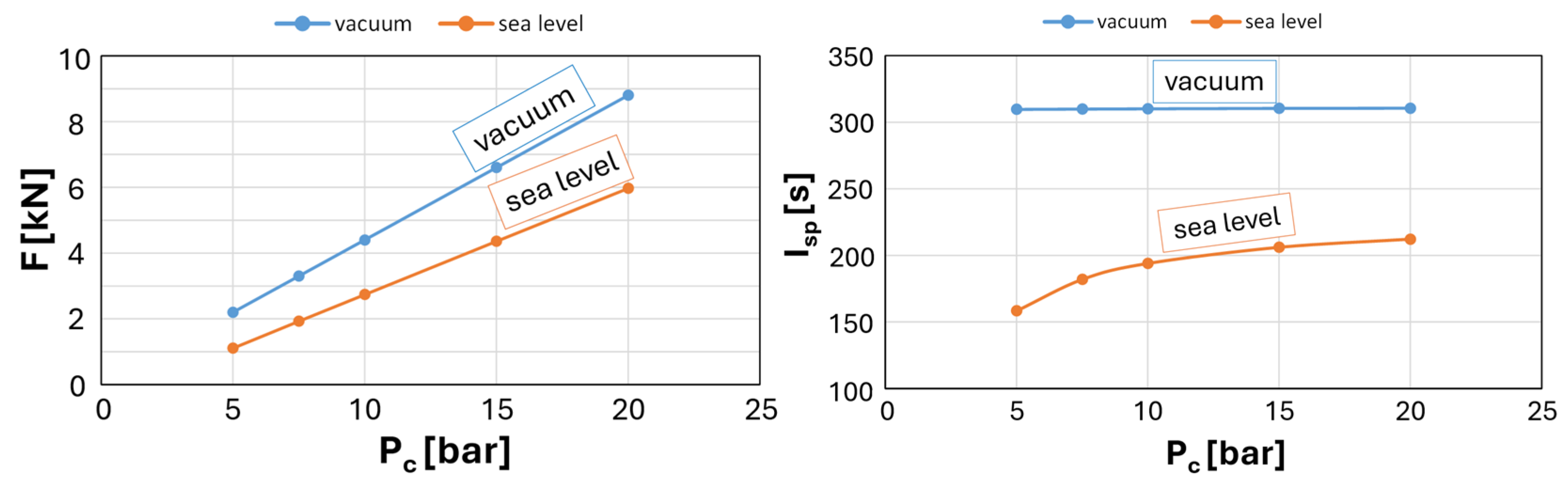
The engine is designed to deliver 6 kN of nominal thrust at sea level, with deep throttling capability down to 1.2 kN. Such a thrust modulation range enables precise maneuvering operations, including orbit insertion, station-keeping, and terminal descent phases. The combustion chamber operates at 20 bar at full thrust, ensuring an optimal balance between performance and structural design limits. One of the high-level requirements given by ESA is to exceed 310 s of specific impulse at nominal conditions, with a minimum of 275 s maintained throughout the throttling envelope. These values reflect both the efficiency of the propellant combination and the engine cycle. The geometry of the engine, constrained to a maximum length of 1000 mm and a diameter of 500 mm, supports integration into compact landers, ascent vehicles, or modular propulsion units, where mass and volume margins are often stringent. These requirements define a robust design space for a sustainable propulsion solution supporting future interplanetary mobility.
2.2. Testing Object
The performance analysis of butyl alcohol in combination with 98% hydrogen peroxide was carried out using Chemical Equilibrium with Applications (CEA) code [
29]. Each combustion chamber and nozzle configuration was characterized by key geometric parameters: chamber length (L
c), chamber diameter (D
c), throat diameter (D
t), nozzle length (L
e), exit diameter (D
e), and the nozzle expansion ratio (A
e/A
t). Performance metrics were evaluated under sea-level and vacuum conditions to comprehensively assess engine behavior across operational environments. In the context of throttled sea-level operations, particular attention must be given to nozzle flow regimes. In the present case, nozzle behavior spans under expanded, overexpanded, and ideally expanded conditions depending on the thrust setting. The risk of flow separation within the nozzle is particularly concerning at low thrust levels. The Summerfield criterion was applied to address this, requiring that the exit pressure remains above 0.6 bar for the minimum thrust setting of 1.2 kN. To relate exit pressure to chamber pressure and the expansion ratio, the isentropic relation is used for supersonic nozzle flow, where we can express the critical condition as [
30]:
where:
P0—chamber pressure, bar;
Pe—nozzle exit pressure, bar;
Me—Mach number at nozzle exit as a function of area ratio Ae/At;
γ—specific heat ratio.
An iterative approach was used to converge on a viable engine geometry that satisfies these constraints. A fixed nozzle efficiency of 96% and a combustion efficiency of 96.9% were assumed throughout, resulting in an overall system efficiency of 93%. The final design parameters derived from this analysis are summarized in
Table 2. Visualization of the nozzles is presented in
Figure 1.
The next step was to verify whether the final geometry dimensions met the requirements in a vacuum. At both vacuum and sea-level conditions, the specific impulse and thrust were calculated for different combustion chamber pressure values. The results are presented in
Figure 2.
Based on the preliminary performance analysis, a prototype engine for sea-level testing was designed and manufactured. Given the short-duration nature of the planned tests, 316 L stainless steel was selected as the structural material for the bolted combustion chamber. ELLOR DS4 graphite was employed for the nozzle due to its favorable thermal resistance properties under sea-level operating conditions.
One of the most critical aspects of the propulsion system is the ignition method. Since 98% hydrogen peroxide is not hypergolic with butyl alcohol, a catalytic decomposition to initiate ignition was adopted. In this method, the oxidizer is decomposed in the catalyst bed, releasing high thermal energy in the form of a gas mixture consisting of oxygen and superheated steam, with adiabatic temperatures exceeding 1200 K. Hot gases ensure rapid and reliable ignition of the subsequently injected fuel, minimizing the risk of ignition delay or hard-start conditions. The primary drawback of catalytic ignition is the added complexity and mass due to the catalyst system, as well as the limited operational lifetime of the catalyst. However, this method enables the engine to operate in a monopropellant mode under certain conditions, which offers the potential for deep throttling and flexible mission profiles. Additionally, this injection strategy can shorten the fuel combustion zone, reducing the required chamber length.
Catalysts used for hydrogen peroxide decomposition were prepared in-house using commercially available alumina ceramic carriers in spherical form. The Institute of Aviation employed a standard preparation protocol involving wet impregnation of the support material in a potassium permanganate solution, followed by drying and thermal calcination. The final product consisted of ceramic-supported manganese oxide catalysts.
The first section of the catalyst bed consisted of a 20 mm high NiCrAl metal foam with a pore size of 1200 µm, coated with a manganese oxide active phase. This configuration combines the favorable decomposition uniformity of metal foams with the low pressure drop associated with ceramic pellets. A schematic view of the catalyst bed configuration is presented in
Figure 3.
Hydrogen peroxide is injected into the catalyst bed by a non-impinging showerhead injector. This injector featured 256 orifices, each 0.7 mm in diameter, designed to ensure uniform distribution over the catalyst surface. Water flow tests were conducted at various supply pressures to evaluate discharge coefficients, mass flow rates, and pressure drops. The measured discharge coefficient was 0.75 ± 0.02 across all operating points. Based on these results, flow characteristics were recalculated for 98% H2O2 to establish performance expectations under actual conditions.
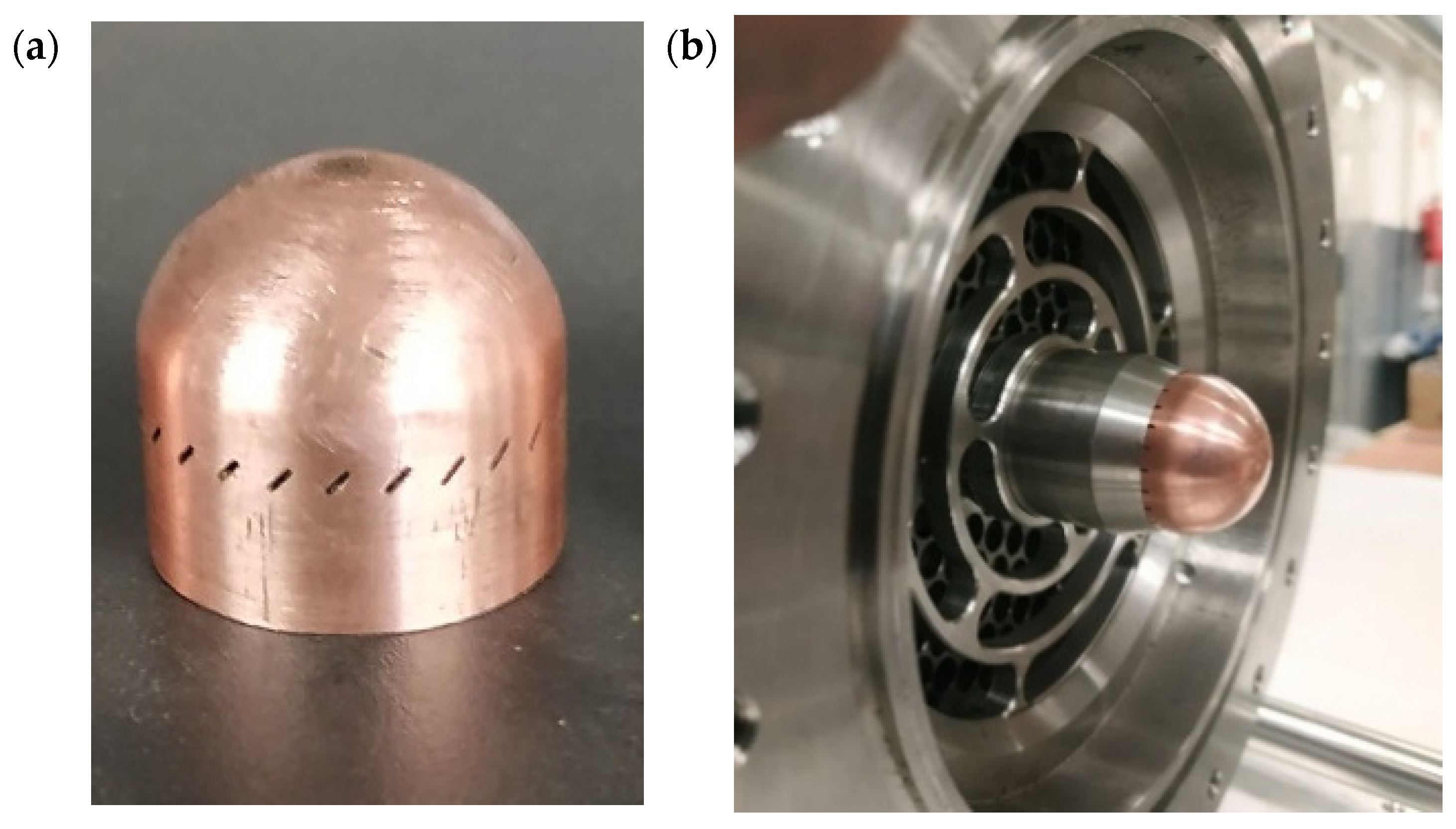
For fuel injection, a pintle injector, a well-established configuration for throttleable liquid-propellant rocket engines (LPREs), was selected. The pintle injector offers good performance and deep throttling capability. Its inherent advantages include reduced susceptibility to combustion instabilities, improved propellant mixing efficiency, and cost-effective manufacturing. The throttling is achieved by an axially movable needle that regulates the annular flow area. This design has gained traction in recent years due to its adaptability and scalability. In this early development phase, a micrometer screw mechanism was used to adjust the position of the pintle with high accuracy as illustrated in
Figure 3. The micrometer screw was mounted using a custom spacer element, and future iterations will require a more robust and automated actuation system. The pintle tip is integrally connected to the fuel manifold, with the fuel routed through an internal channel toward the injector head. The pintle tip presented in
Figure 4 is machined from copper alloy and features a central axial orifice to enable effective regenerative cooling.
In addition to the baseline configuration, an alternative pintle injector with slotted orifices was developed. The slots were drilled at a 45° angle, with a thickness of 0.5 mm and a length of 2 mm. A total of 25 orifices were used in this configuration. Experimental water flow tests were conducted at supply pressures of 5, 10, 15, and 20 bar. The pintle was systematically adjusted during testing to study its effect on key flow parameters. The results were analyzed to establish the relationship between pintle position, supply pressure, discharge coefficient, and mass flow rate, as presented in
Figure 5.
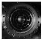
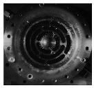
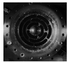
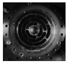
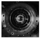
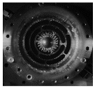
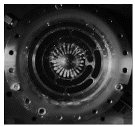
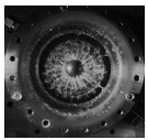
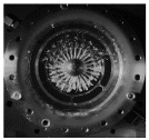
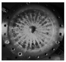
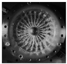
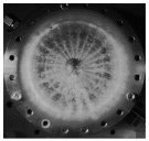
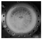
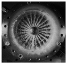
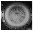
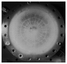
Representative cold-flow test images used for injector characterization are summarized in
Table 3. The tests employed high-speed imaging with a MEMRECAM HX-3 system (NAC Image Technology, Howell, MI, USA), operating at 50,000 frames per second with a 0.1 ms exposure time. This setup enabled high-fidelity visualization of dynamic flow behavior. The captured images provided critical insights into spray pattern formation, atomization quality, and flow stability under various conditions. Analysis of the footage revealed that higher injection velocities were observed at more restricted pintle positions. This suggests deeper fuel jet penetration into the decomposed hydrogen peroxide stream, which may become significant at lower thrust levels, where oxidizer mass flow is reduced. Consequently, excessive throttling could lead to increased thermal loading on the chamber walls, raising the risk of local burn-through. These observations will guide future injector optimization and chamber cooling design.
The propellant feed system governed the delivery of fluids from the tanks to the combustion chamber and consisted of a series of solenoid valves. Coaxial, direct-acting two-way valves are operated within a 0–40 bar pressure range.
2.3. Instrumentation and Test Sequence
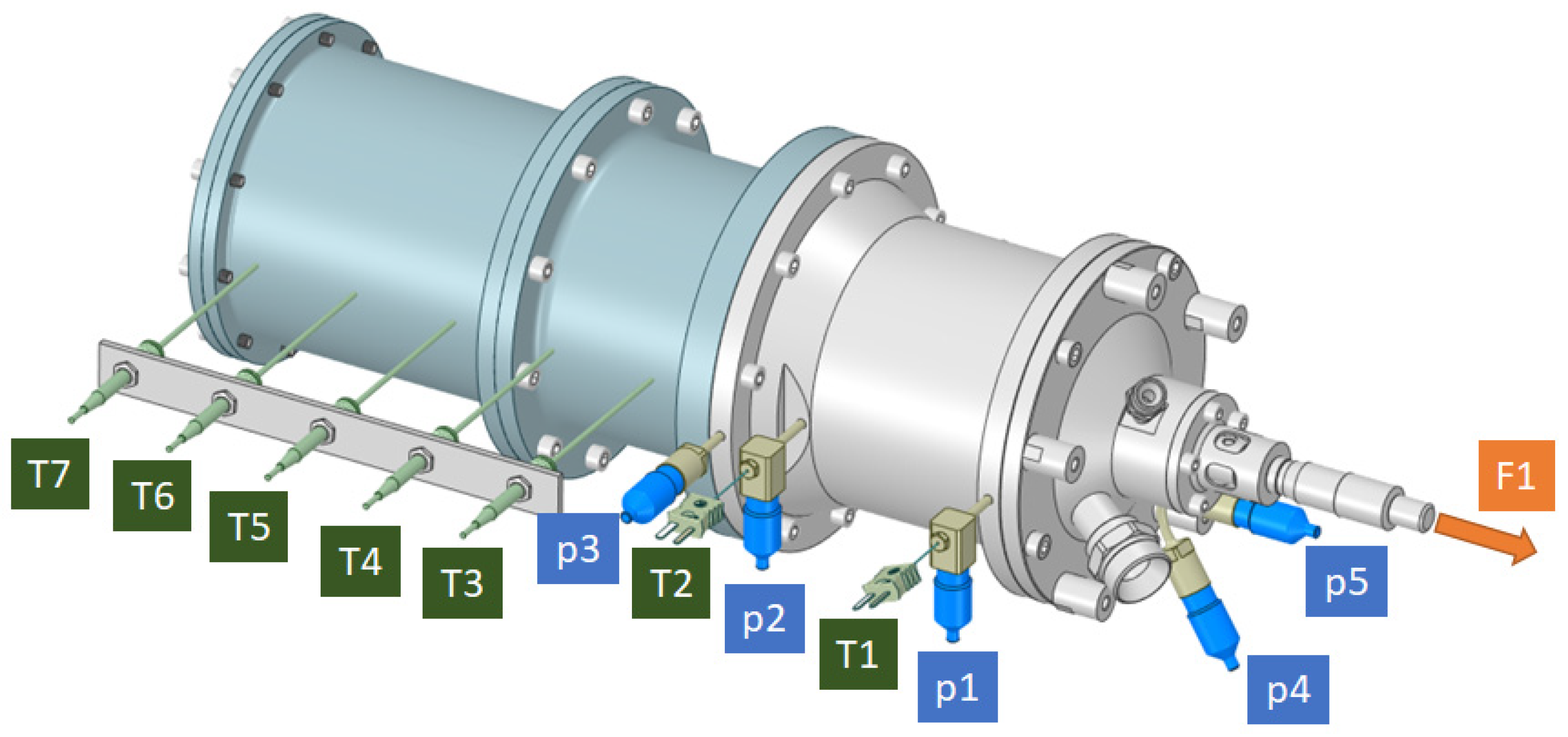
The engine and test stand were instrumented with sensors and control systems to enable comprehensive data acquisition and real-time monitoring. The layout of all measurement points and control elements is presented in
Figure 6 and
Table 4.
Temperature measurements were obtained using K-type thermocouples, offering a measurement range of 0 to 1000 °C with an accuracy of ±0.4% full scale (FS) within the 376–1000 °C interval. Chamber and feed system pressures were measured using Keller PA-21PY pressure transducers, rated for 0–40 bar with an accuracy of ±0.25% FS. Mass flow rates of hydrogen peroxide (HTP) and butyl alcohol were measured using Coriolis flow meters supplied by Rheonik: the RHM 15 (0–240 kg/min) and RHM 06 (0–36 kg/min), both with an accuracy of ±0.1% FS. Thrust was measured via an EMS50-10 kN strain-gauge-based force sensor, with a range of up to 10 kN and ±0.5% FS accuracy. Data acquisition and control were performed using a National Instruments PXIe system connected to a host PC. The system operated at a sampling frequency of 10,000 Hz, ensuring high temporal resolution across all recorded signals.
The hot-fire testing campaign was divided into two distinct phases to thoroughly characterize engine performance. In the first phase, the engine operated in monopropellant mode, using hydrogen peroxide only. This phase investigated the decomposition process and assessed the stability of the system, ignition characteristics, and thrust behavior across different mass flow rates. Parameters recorded during this phase included supply pressure, pressure drop across the catalyst bed, catalyst bed segment temperatures, mass flow rates, combustion chamber wall temperatures, and generated thrust. Flow control for H
2O
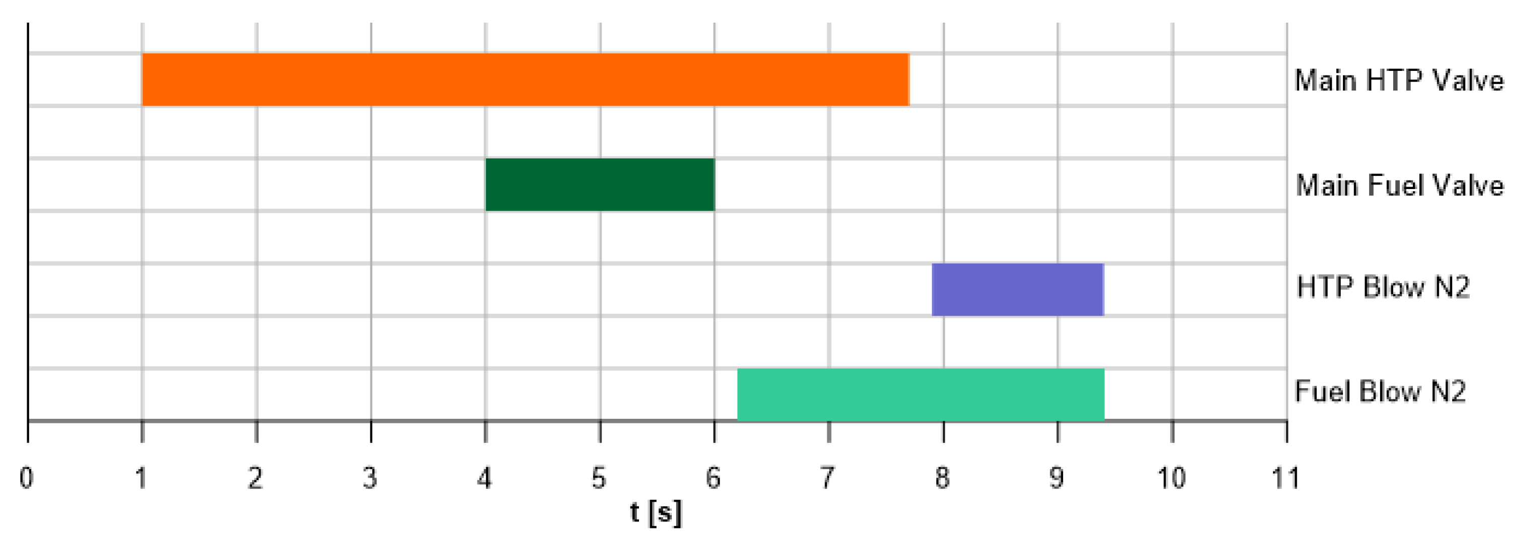
2 was achieved by adjusting the tank pressure, while the pintle position and tank pressurization regulated the flow of butyl alcohol. In the second phase, the engine was tested in bipropellant mode. Hydrogen peroxide was supplied for 6.7 s, and after a 3 s delay (to allow catalytic decomposition), fuel injection commenced and continued for 2 s (
Figure 7). Before each run, the feed lines were purged to minimize start-up instabilities.
Table 5 shows the test sequence, detailing the duration, objectives, and key operations associated with each stage of the combustion campaign.
3. Monopropellant Test Campaign
The first test campaign focused on monopropellant operation, with Phase 1 dedicated to the experimental optimization of the engine hardware through a series of hot-fire tests. The primary objective was to assess whether the catalyst bed configuration ensured the complete decomposition of hydrogen peroxide while delivering stable and efficient performance. Tests were conducted at 20%, 50%, and 100% of the nominal hydrogen peroxide mass flow rate, with run durations outlined in
Table 5. Changes in thrust, mass flow rate, pressure, and temperature were recorded and are presented in
Figure 8.
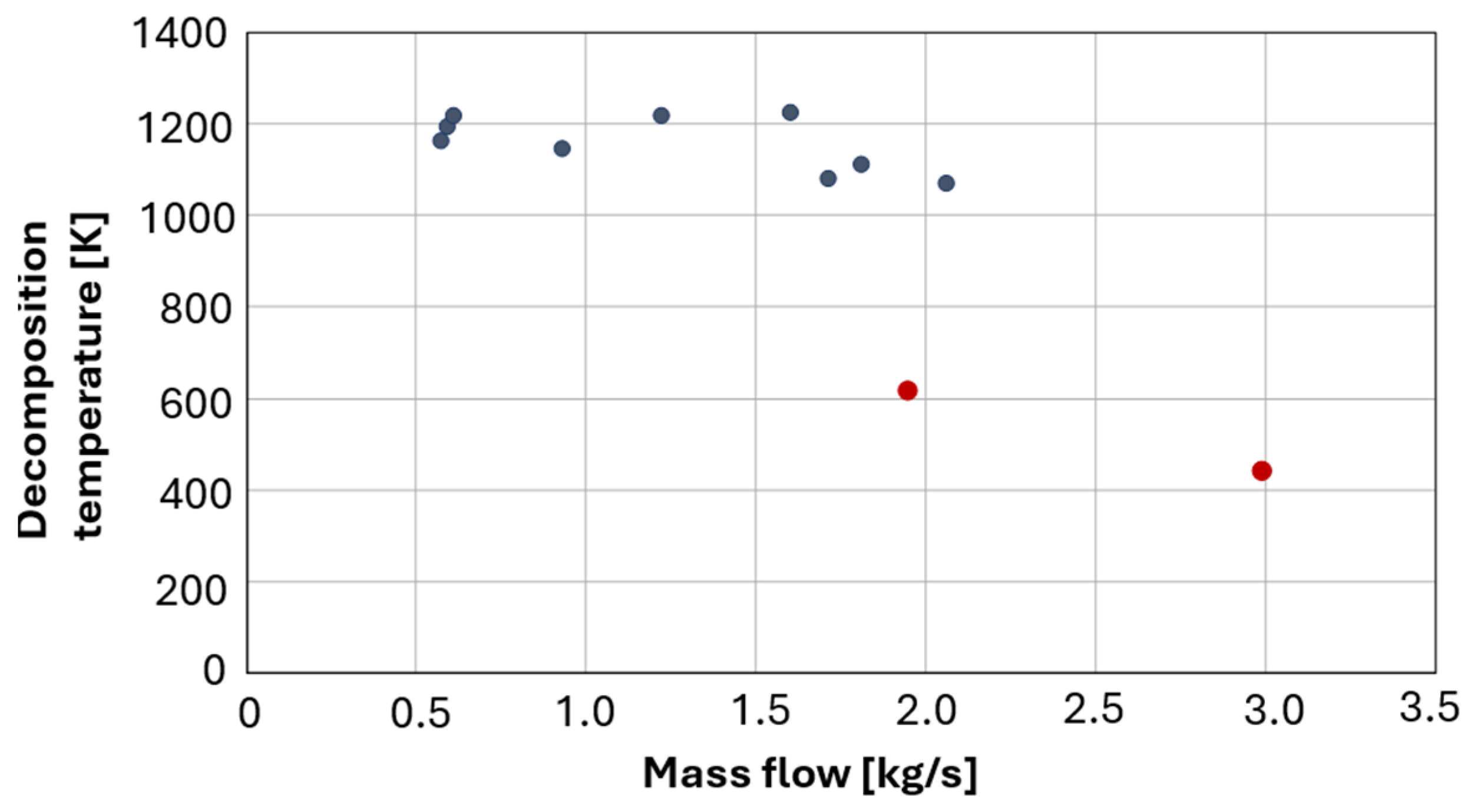
The analysis revealed that complete decomposition was not achieved at the highest flow rate (100%), with a notable drop in decomposition temperature observed downstream of the catalyst bed at approximately 2 kg/s. Additional tests at this flow rate confirmed increasingly incomplete decomposition (lower temperature in the catalyst bed upstream), suggesting a performance limit of the current bed configuration. A graph illustrating the relationship between decomposition temperature and flow rate is provided in
Figure 9. Navy-blue markers correspond to temperatures approaching the adiabatic value, whereas red markers indicate substantially lower temperatures, which are indicative of incomplete decomposition.
The catalyst bed loading factor emerged as the most influential among all design parameters. To maximize the temperature of the reaction gases downstream of the catalyst, careful selection of the bed diameter is critical. The loading factor can be defined in terms of both surface and volume, representing mass flow rate per unit cross-sectional surface area (kg/m
2·s) or per unit volume of the catalyst bed (g/cm
3·s), respectively. This dual definition accounts for both the diameter and the total volume of the catalyst pellets. Experimental results indicated optimal decomposition temperatures were achieved when the surface and volume loading factors remained below 200 kg/m
2·s and 3 g/cm
3·s, respectively. These relationships are shown in
Figure 10.
To ensure complete decomposition at full flow rate (100%), it was determined that the catalyst bed must either be extended in length or increased in diameter. Due to geometric constraints limiting the total engine length, increasing the diameter was identified as the most practical solution. The analysis showed that a catalytic chamber with a diameter D = 160 mm instead of 108 mm is required to maintain the desired loading factor under full-flow conditions. The results of this analysis are summarized in
Table 6.
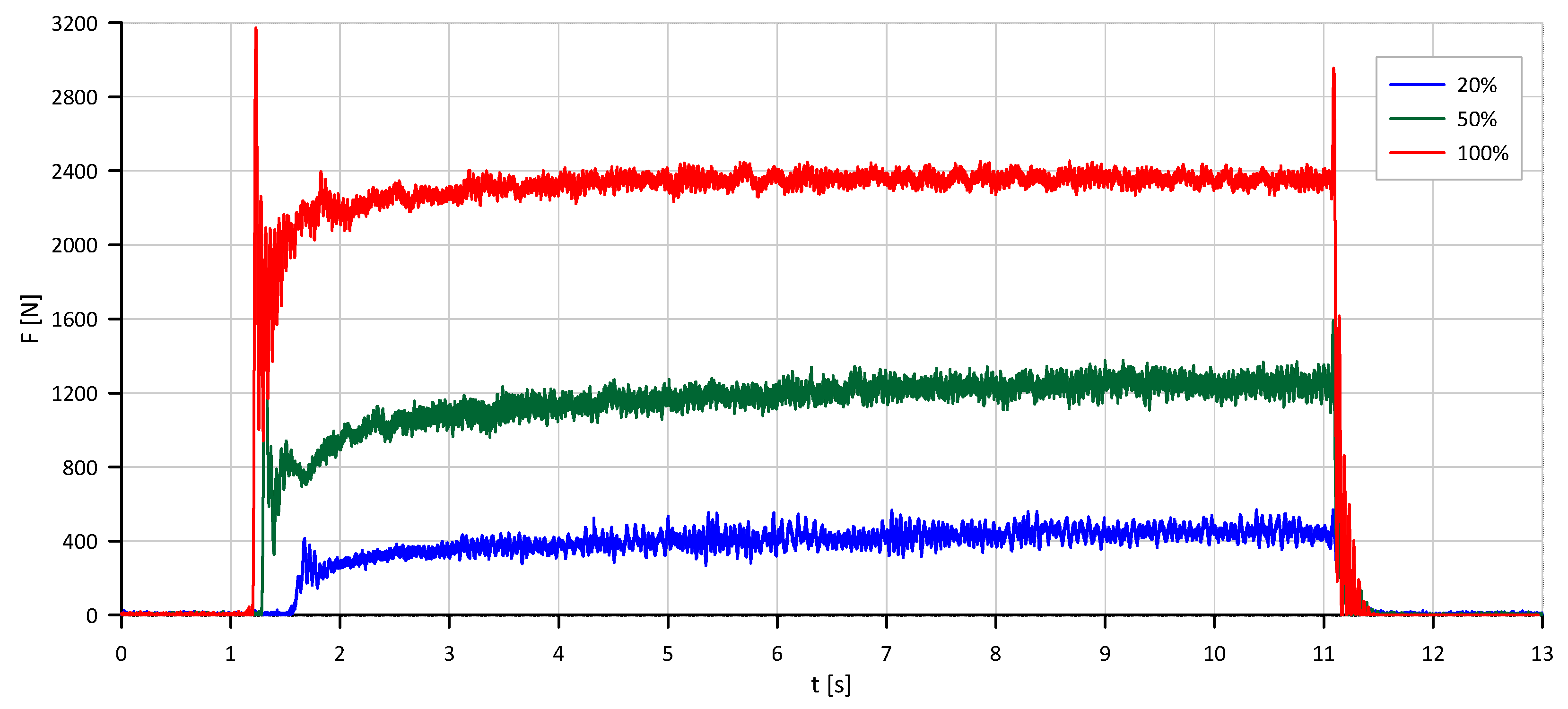
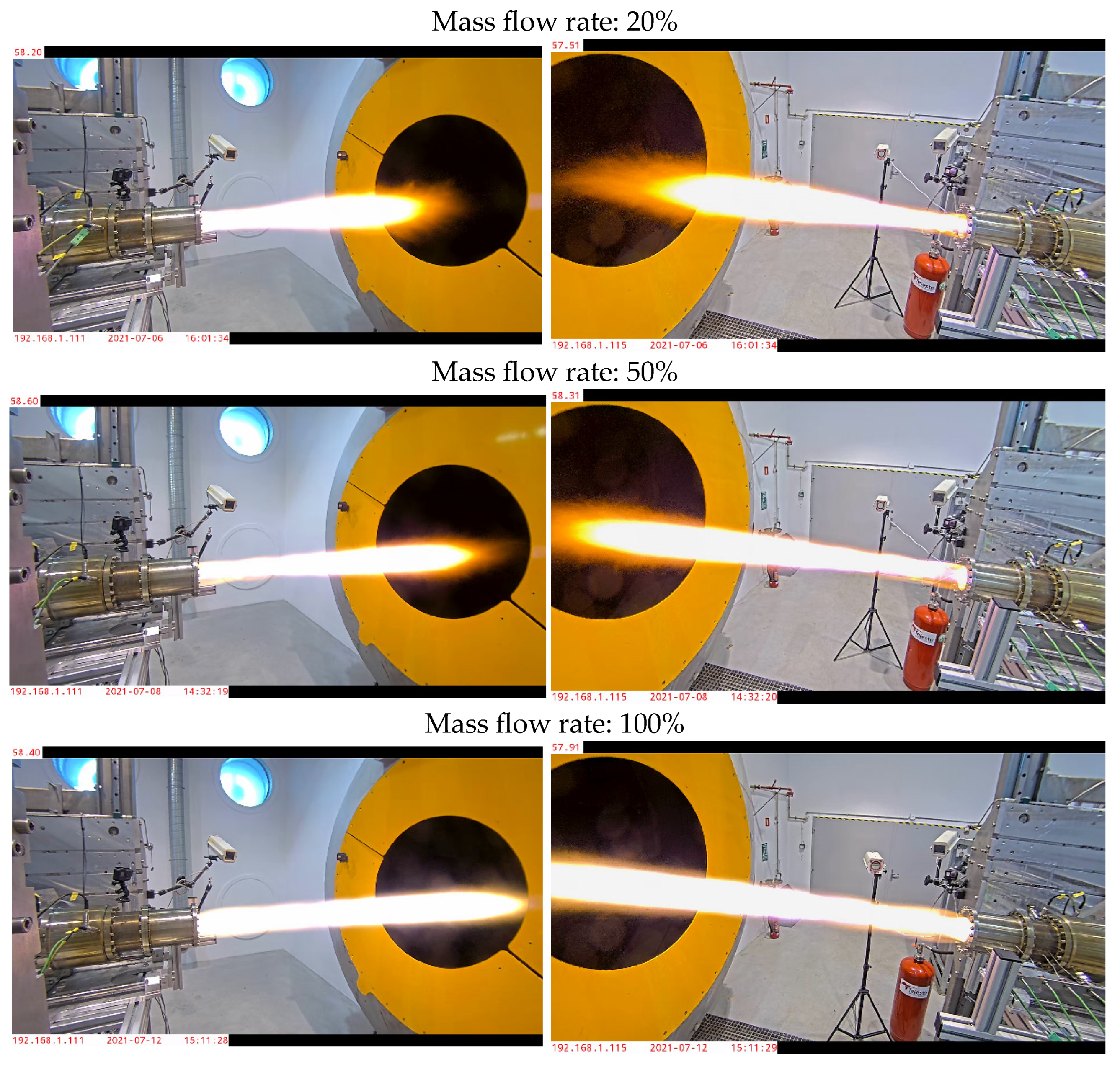
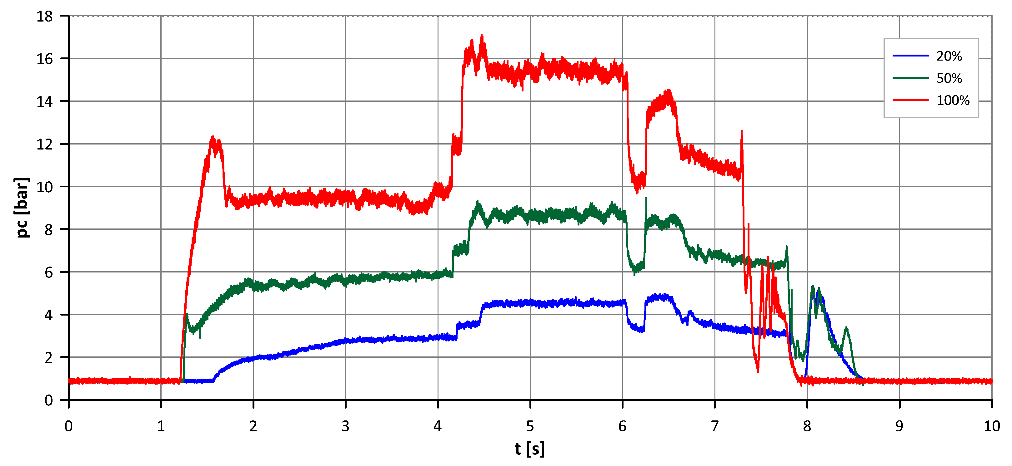
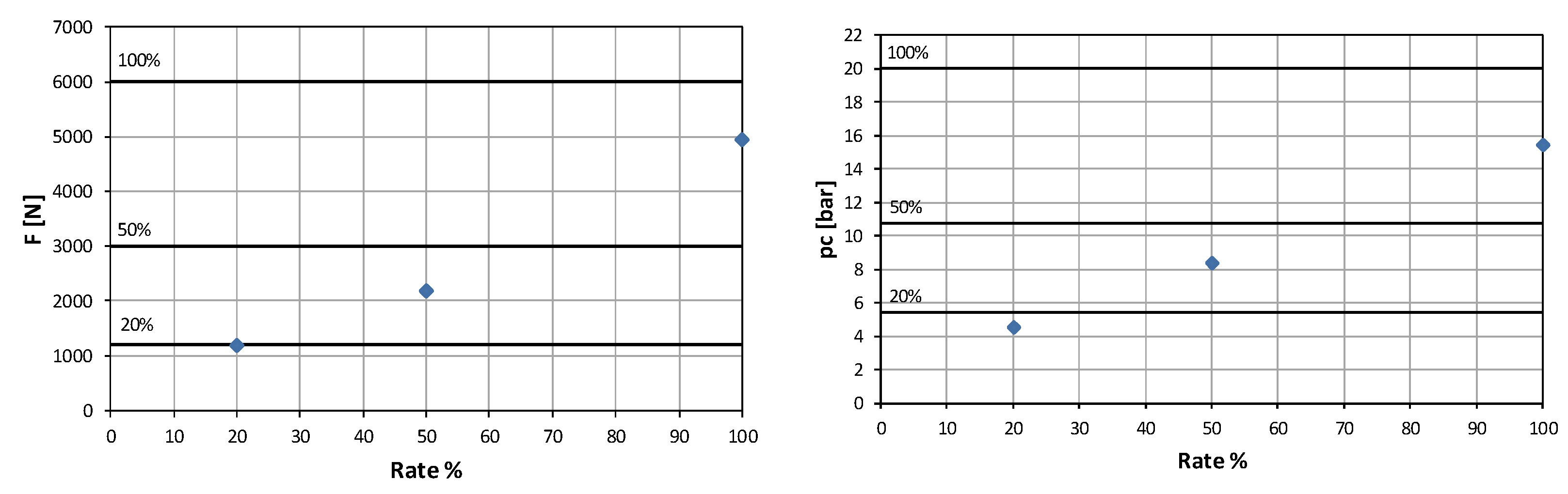
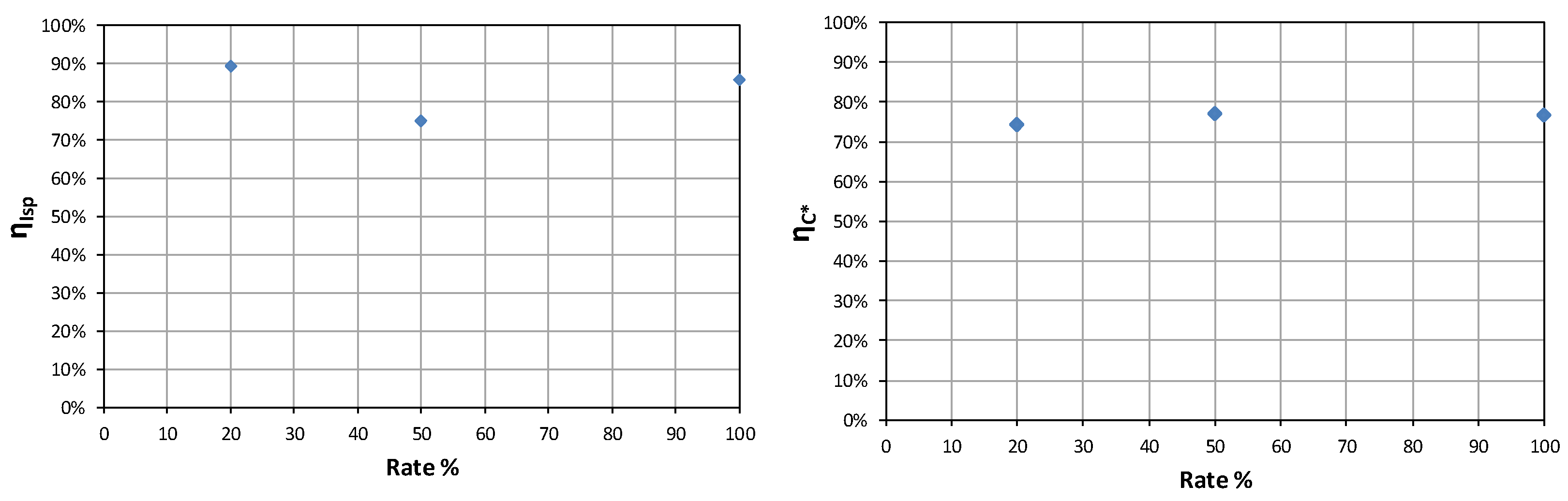
Final validation tests were carried out at 20%, 50%, and 100% mass flow rates with run durations of 3, 5, and 10 s. Representative test results, including thrust and combustion chamber pressure profiles, are shown in
Figure 11 and
Figure 12. These results confirmed the necessity of geometric adjustments to maintain thermal efficiency and decomposition completeness at higher flow rates.


