1. Introduction
Composite materials (CM) are materials that possess enhanced properties, consisting of two or more components with distinct characteristics, which are created through physical or chemical processes [
1]. These materials are widely used in the aerospace industry for both loading and non-loading structures due to their remarkable weight reduction capabilities, innovative design potential, and favorable manufacturability [
2]. Commercial transport aircraft, such as the Boeing 787 and the Airbus A350, are constructed with over 50% CM. In general aviation, some aircraft types, like the Cirrus SR22 and the Diamond DA40, are made entirely of CM due to the smaller size of their fuselages, simpler structures, and fewer components [
3]. Typically, the cost of selecting CM for aircraft is higher than that of metals. Statistical analyses indicate that approximately 70% of these costs are associated with manufacturing. Consequently, composite manufacturers are actively working to develop cost-effective manufacturing processes aimed at minimizing the overall costs of composite applications.
High reliability, low weight, and low cost have always been critical requirements for the development of composites in civil aviation. However, with the continuous advancement of the low-altitude economy and the emergence of new aircraft types, the application of cost-effective composite technologies in these new aircraft encounters several challenges and issues. These challenges relate to various aspects of aerospace composite structure design [
4,
5], manufacturing [
6,
7,
8], and evaluation [
9,
10]. The most common challenge is coordinating the balance between safety and economic considerations, which has garnered significant attention from both the aviation industry and academia. In recent years, China has implemented various measures to promote the development of low-cost technologies related to CM. An important initiative is to conduct type certification for a specific type of all-composite aircraft in accordance with the China Civil Aviation Regulation Part 23 (CCAR 23). The production process utilizes low-cost wet molding technology for composite materials, which can decrease raw material costs by approximately 50%. Additionally, it eliminates the necessity of investing in expensive curing and manufacturing equipment, further lowering manufacturing costs while achieving weight reduction. This process presents a significant opportunity for general aviation to reduce expenses associated with composite materials.
The most significant issue with the wet molding process is the relatively poor quality of the parts, particularly characterized by high porosity. Researchers have established that porosity adversely affects mechanical properties [
11,
12,
13,
14,
15,
16,
17,
18]. D. Abraham et al. [
11] noted that an increase in porosity negatively affects the mechanical properties of composites. Judd and Wright [
12] reported that a 1% increase in porosity results in a 7% reduction in short-beam shear properties. D. Abraham [
13] and T. Staffan Lundstrom [
14] provided a comprehensive overview of the mechanisms behind porosity formation during resin transfer molding and its effects on mechanical properties. Since 1970, China has concentrated on the research, development, and production of composite structures for the aerospace industry. Chen Wen et al. [
16] proposed a method to significantly reduce component porosity by adjusting various process parameters and examined the effect of porosity on mechanical properties. Shang Jianzhao et al. [
18] suggested future research directions for low-cost preparation processes. Although the aforementioned researchers have made significant contributions, there remains a notable gap in the study of porosity in low-cost wet molding composites and its influence on mechanical properties.
According to the manufacturing experience of a specific type of aircraft discussed in this paper, the wet molding process of composite materials exhibits significant variability compared to the prepreg manufacturing process, which consequently results in increased porosity during production. Currently, there is no publicly available standardized system for the airworthiness technology verification of composites produced through wet molding processes on a global scale. Research on prepregs has demonstrated that high volumetric porosity (hereinafter referred to as porosity) presents challenges to aircraft safety, introducing considerable uncertainties into the airworthiness verification of composite structures. This issue is particularly pronounced when assessing material stability, manufacturing repeatability, and quality consistency in accordance with relevant airworthiness regulations, leading to substantial technical challenges in airworthiness verification. This paper examines the effect of porosity in wet molding composites on key mechanical properties, using an aircraft with an airworthiness certificate as a case study. It quantifies the degree of influence through a load coefficient and proposes a method for incorporating this load coefficient into full-scale composite static verification to ensure safety. Additionally, the paper presents an airworthiness compliance approach for similar scenarios, with the goal of developing a safe and reliable methodology for airworthiness compliance in this process.
2. Materials and Tests
2.1. Materials and Process
The majority of the specific type of aircraft is constructed from composite materials, except for the wing spar cap, which is manufactured using a low-cost wet lay-up vacuum bagging process. This composite material consists of a reinforcement and a matrix. This reinforcement, designated W3021, is a civilian fabric, T300 grade, twill weave, 3K in both warp and fill yarn, with a weight per unit area of 198 g/m2. The matrix is composed of two components: resin LR285 and hardener LH287. LR285 and LH287 are mature materials developed by the German company HEXION, a laminating resin system approved by the German Federal Aviation Authority Application with different pot lives for processing glass, carbon, and aramid fibers, featuring high static and dynamic load ability, can be used in the production of gliders, motor gliders, motor planes, boats, shipbuilding, sports equipment, model airplanes, molds, and tools. When manufacturing composite material structures, the mixed weight ratio of LR285 and LH287 is 100:40. The density of the used fibers is approximately 1.780 kg/m3 and the density of the matrix is approximately 1.172 kg/m3.
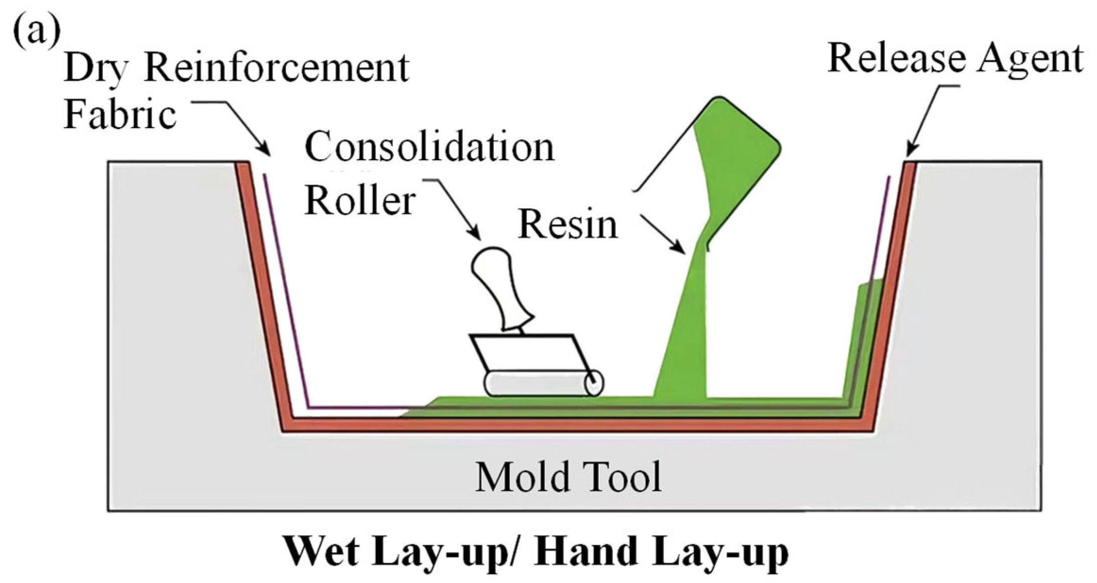
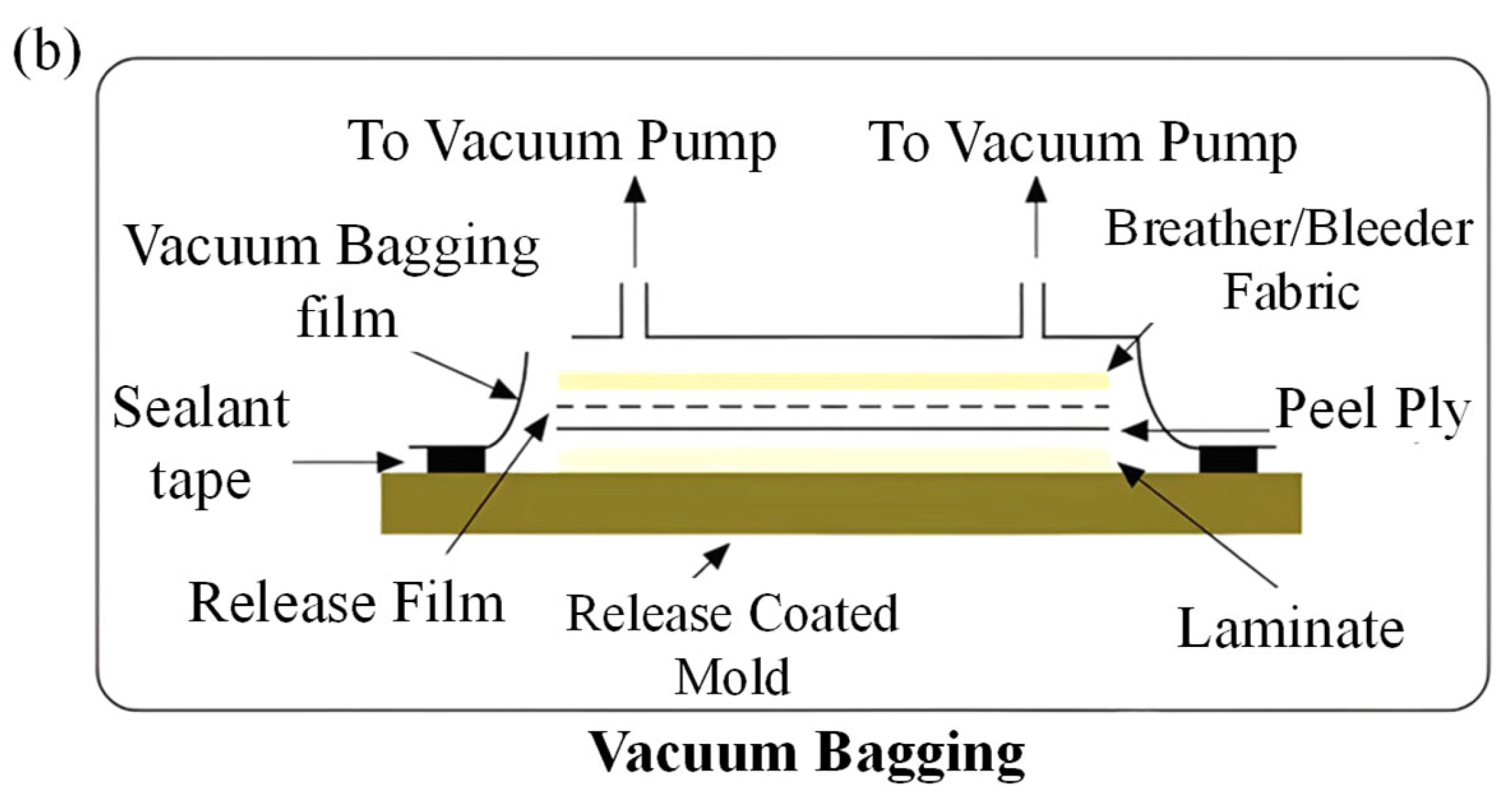
There are several aircraft types developed in accordance with CCAR-23 airworthiness regulations. Most of these types are constructed using (CM), with some being composed entirely of CM. When selecting CM and manufacturing processes, the emphasis is placed on cost-effectiveness and manufacturing efficiency while ensuring that the components meet performance requirements. The low-cost wet molding process for (CM) combines the advantages of both the hand lay-up process (
Figure 1a) and the vacuum forming process (
Figure 1b). It effectively addresses the limitations of the hand lay-up method, including low productivity, prolonged production cycles, difficulties in maintaining product quality, and inadequate performance stability [
19]. This innovative approach enhances product quality, strength, and cost-effectiveness without significantly increasing the expenses associated with the original hand lay-up process. Consequently, it facilitates improvements in product quality and strength while preserving cost efficiency, thereby achieving a balance between economy, performance, and lightweight design in aircraft manufacturing.
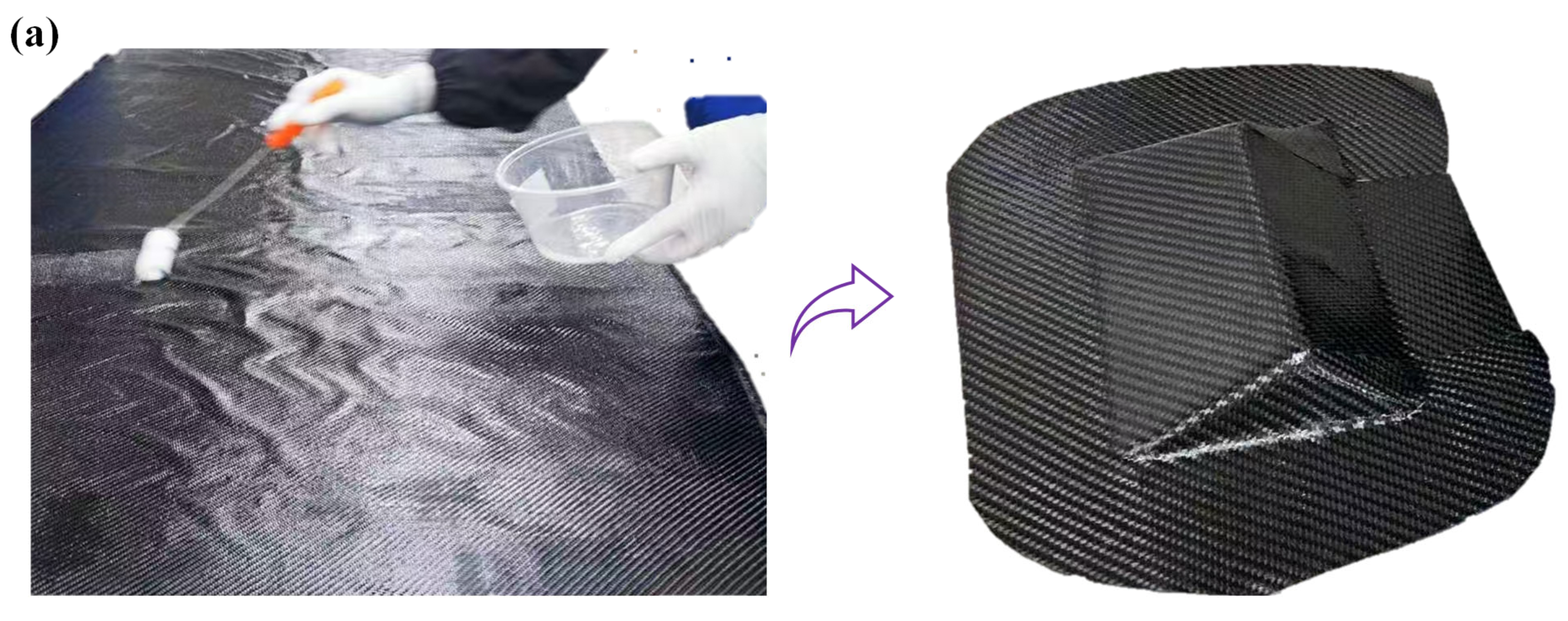
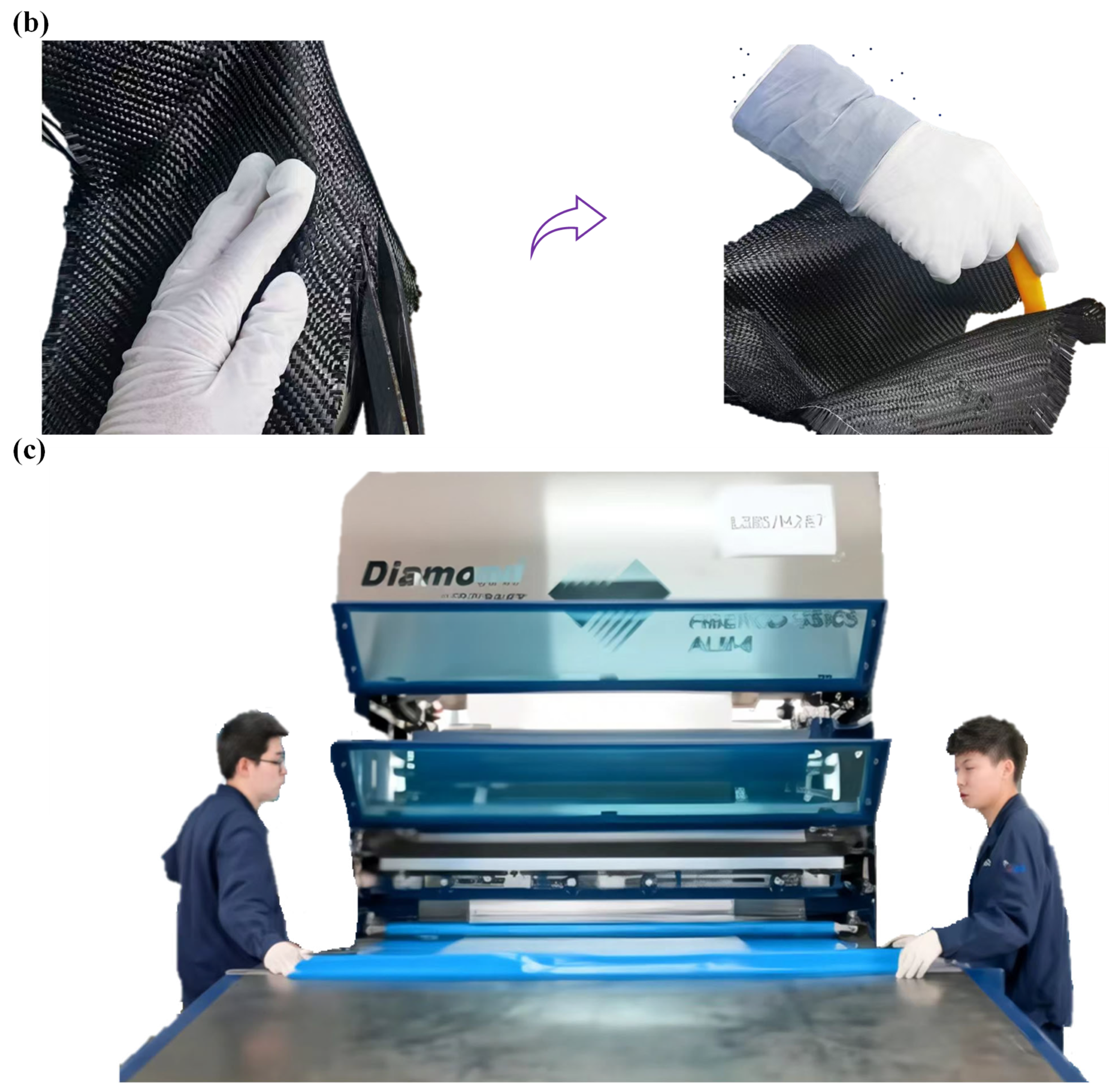
For the wet vacuum bagging molding process, there are currently three common preparation methods, with the primary differences residing in the techniques used to impregnate the reinforcing materials. The details are illustrated in
Figure 2. The specific type of aircraft that possesses airworthiness certificates utilizes Method 1. The manufacturing process and parameters for the test plate are identical to those of the actual aircraft structure. First, the resin (LR285) and hardener (LH287) are mixed in a ratio of 100:40, thoroughly combined, and then used to impregnate the carbon cloth (W3021). The prepreg fabric is then placed on the work platform according to the specifications detailed in the drawings. Secondly, the use of vacuum bags and other auxiliary materials is essential for effectively sealing wet fabric bagging. This process requires achieving a vacuum level of at least 99 KPa and allowing for curing at room temperature for 24 h. Thirdly, the parameters for the curing oven were established in accordance with the process specifications, and the test plates were post-cured at 80 °C for at least 15 h. The test plates were then completed.
2.2. Porosity Test
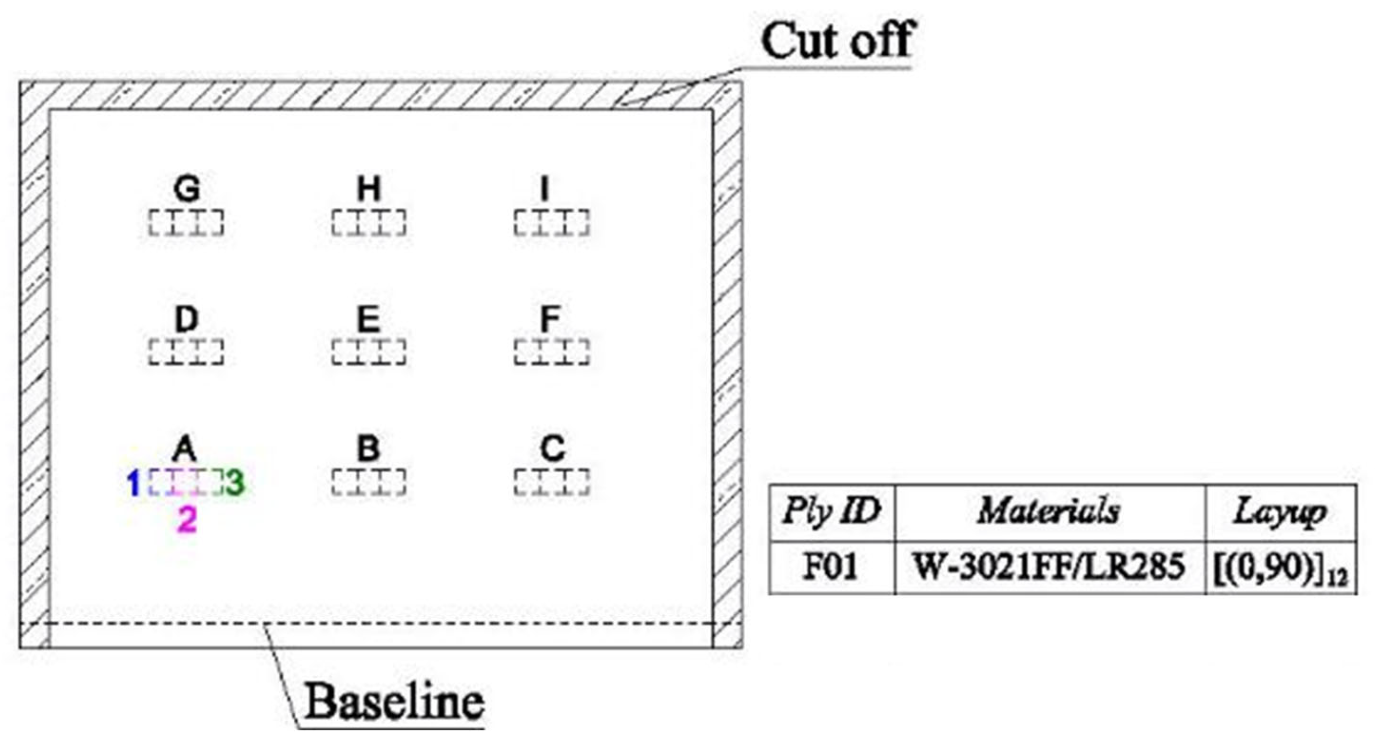
To investigate the porosity in the wet vacuum bagging process, a test panel with layup F01 was manufactured for sampling. The configuration, layup, and sampling method of the test panel are illustrated in
Figure 3. Prior to sampling, a 25 mm edge was trimmed around the test panel to prevent boundary effects from influencing the test results. To assess the characteristics of the porosity, concentrated sampling was performed at multiple locations on the test panel. Nine sites, labeled A to I, were selected, with three specimens collected from each site. In total, 27 porosity specimens were obtained from the entire test panel.
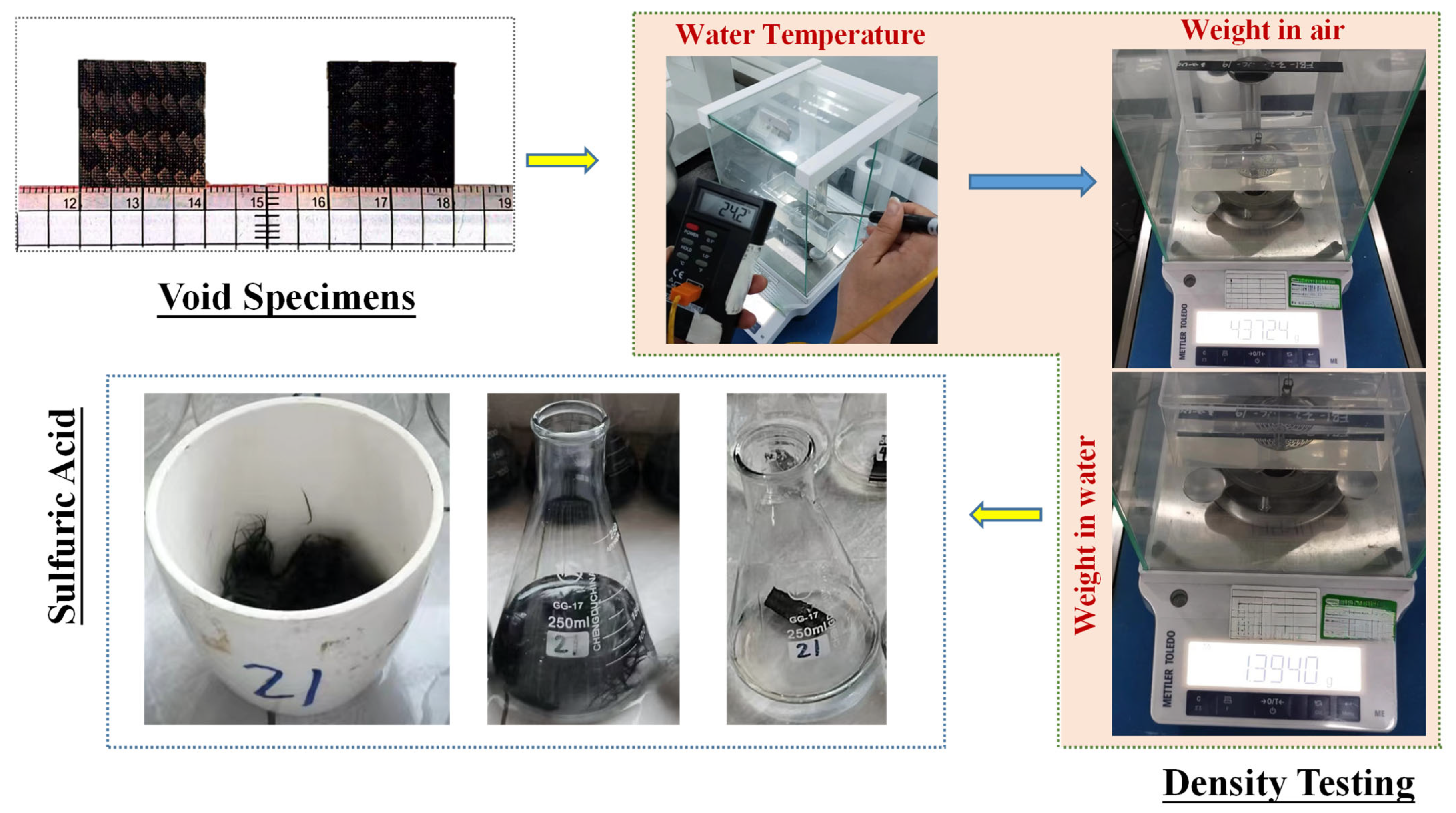
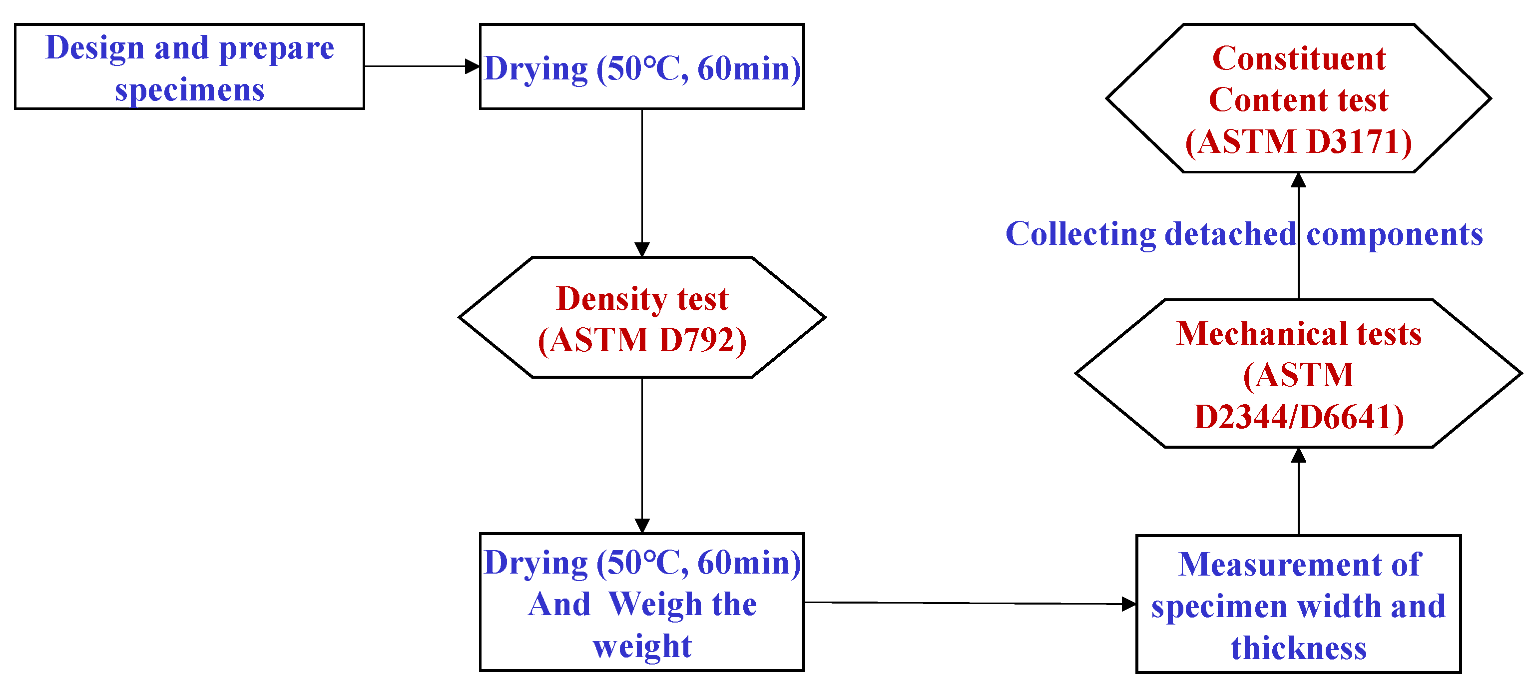
Matrix digestion, used to test the porosity, commonly known as acid digestion, was favored in this work as a destructive method to determine the constituent content of the composite; the detailed procedure is illustrated in
Figure 4. The test procedures were carried out in this work using Sulfuric Acid and Hydrogen Peroxide. The tests were conducted with reference to the recommendations of ASTM D3171 (Method 1, Procedure B). Before the testing procedures, the density of the specimens was measured. The mass of each sample was then measured to the nearest 0.1 mg using an analytical balance; the tests were carried out with reference to the recommendations of ASTM D792. Calculate the density of the specimen as follows:
where a is apparent mass of specimen in air, b is apparent mass of specimen completely immersed in water,
is the standard density of water (
, if the temperature of the water is different than 23 °C, use the density of water listed in Table 3 of ASTM D792 directly.
After performing the tests, the fiber and matrix content volume percent can be calculated according to Equations (2) and (3), while porosity can be calculated according to Equation (4).
where
,
and
are the percentages of the volume of the fibers, matrix, and voids in the composite.
is the mass of the sample after digestion.
,
and
are the densities of the fibers, matrix, and the sample, respectively.
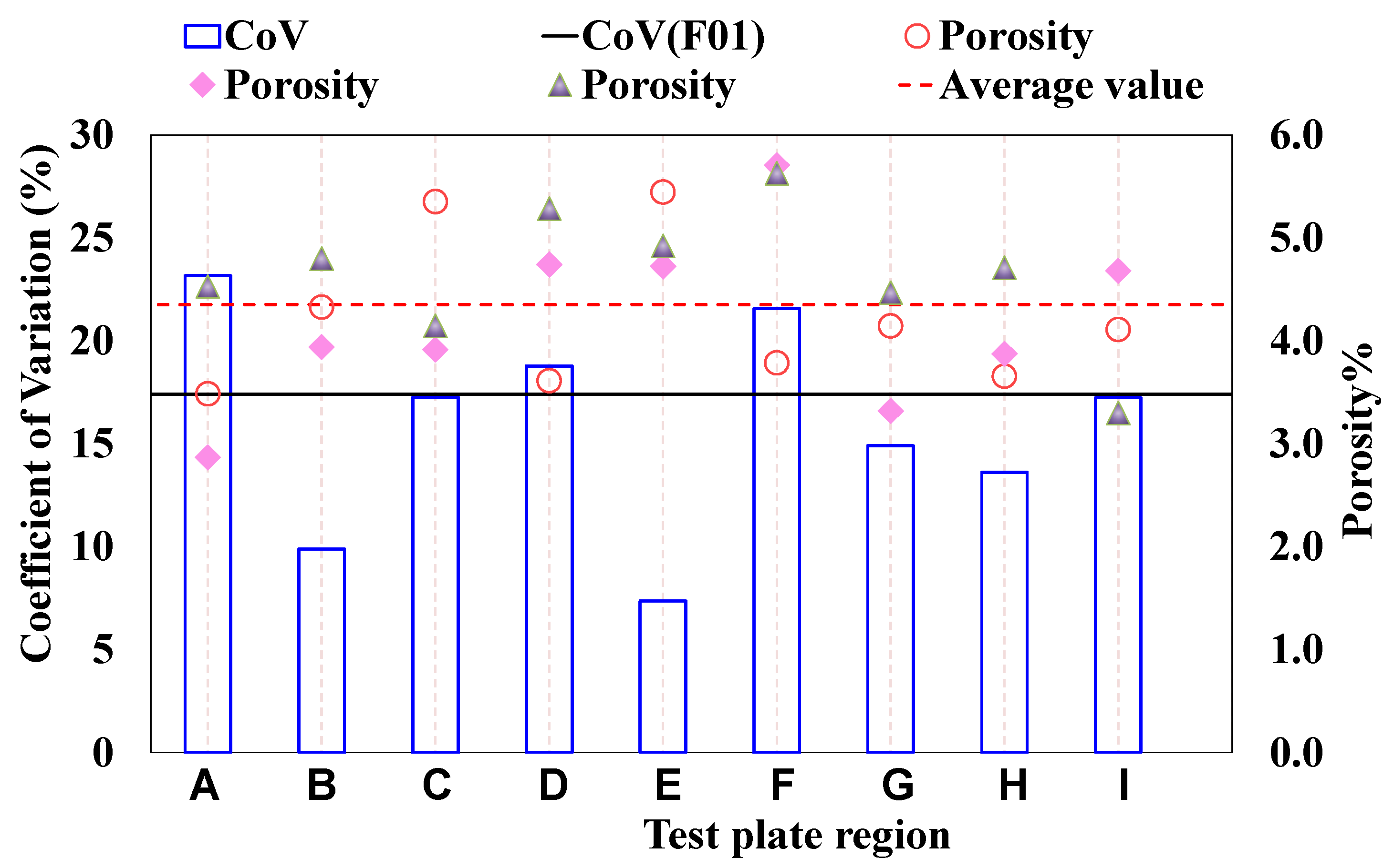
A basic statistical analysis was conducted on the 27 porosity data points, and the results are illustrated in
Figure 5. The analysis indicates that most of the porosity values fall within the range of 2% to 5%. The coefficient of variation (CoV) for porosity across the entire test panel is 17.4%, suggesting a discrete distribution of porosity, even in localized areas (in the same region, the CoV for porosity is predominantly greater than 10%). This finding is consistent with the experimental results reported by J. Tomblin et al. [
20]. According to the regulations outlined in CCAR 23.603 (b), the quality standards for the process must be stringent [
21]. A high coefficient of variation signifies that the material’s stability and quality consistency do not meet regulatory requirements. Furthermore, the aforementioned discreteness has not been evaluated under worst-case scenarios, which poses a potential risk to aircraft safety. To address this issue, it is essential to determine the mechanical properties associated with this level of porosity.
2.3. Mechanical Properties and Porosity Test
To investigate the effect of porosity on the key mechanical properties of composites produced through wet vacuum bagging molding, it is essential to overcome the challenge of simultaneously obtaining two destructive test results—mechanical properties (compressive strength or interlaminar shear strength) and porosity from the same specimen. A novel testing procedure has been developed to achieve these objectives, and the specific testing process is illustrated in
Figure 6.
Two test plates were prepared for fabricating specimens for the non-notched compression test and the interlaminar shear test, respectively. The test environment was room temperature and humidity (RTD), and 50 valid data were collected per tested panel. The test matrix is presented in
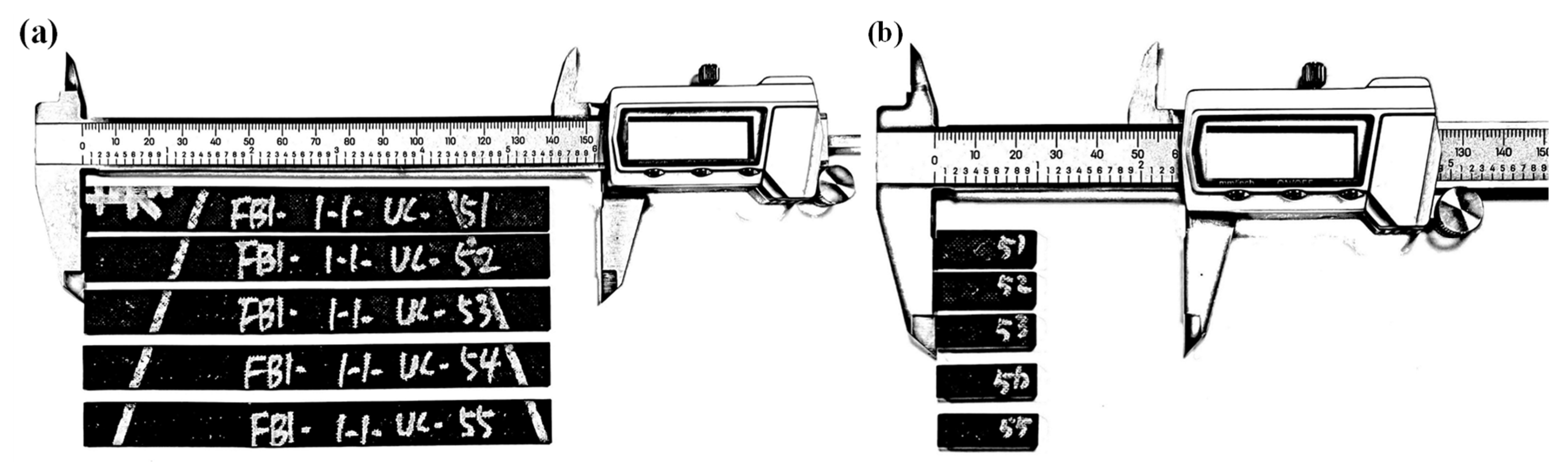
Table 1. The test plate manufacturing process employs the wet vacuum bagging molding technique used in the actual production of this type. The materials utilized have been verified against the certified aircraft type to ensure compliance with the material specifications approved by the Civil Aviation Administration of China (CAAC). The prepared test specimens (
Figure 7 shows some of the specimens) comply with the relevant ASTM standards and have received the Airworthiness Approval Tag from the CAAC. To ensure the accuracy of the porosity value, it is essential that the test specimen have no mass loss during the mechanical property test. Each data record must be comprehensive, including details such as the specimen number, weight, dimensions, density, porosity, failure strength, and failure mode.
3. Results and Discussion
3.1. Mechanical Properties and Porosity Test Results
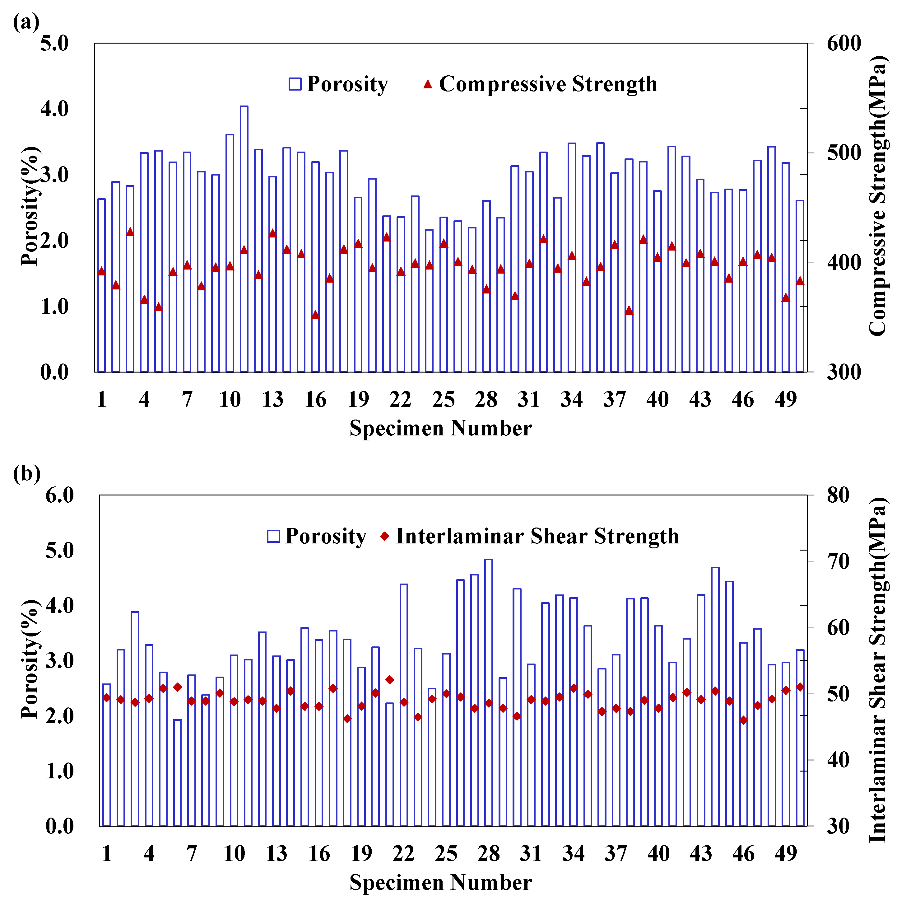
The porosity and mechanical properties of each specimen are presented in a chart format (see
Figure 8). Through basic statistical analysis, the following results were obtained: For the compression specimens, the average compressive strength is 397 MPa, with a CoV of 4.55%. The average porosity is 3.00%, with a CoV of 13.77%. For the interlaminar shear specimens, the average strength is 49 MPa, with a CoV of 2.70%. The average porosity is 3.40%, with a CoV of 20.09%.
3.2. Porosity Characteristics
Each distribution is considered using the Anderson-Darling test statistic, which is sensitive to discrepancies in the tail regions. The Anderson-Darling test compares the cumulative distribution function for the distribution of interest with the cumulative distribution function of the data. The data are first converted to a common representation for the distribution under consideration. For example, for a normal distribution, the data are normalized to a mean of 0 and a standard deviation of 1. An observed significance level (OSL) based on the Anderson-Darling test statistic is computed for each test. If the OSL is less than or equal to 0.05, the hypothesis is rejected (with at most a five percent risk of being in error), and one proceeds as if the data are not from the distribution being tested.
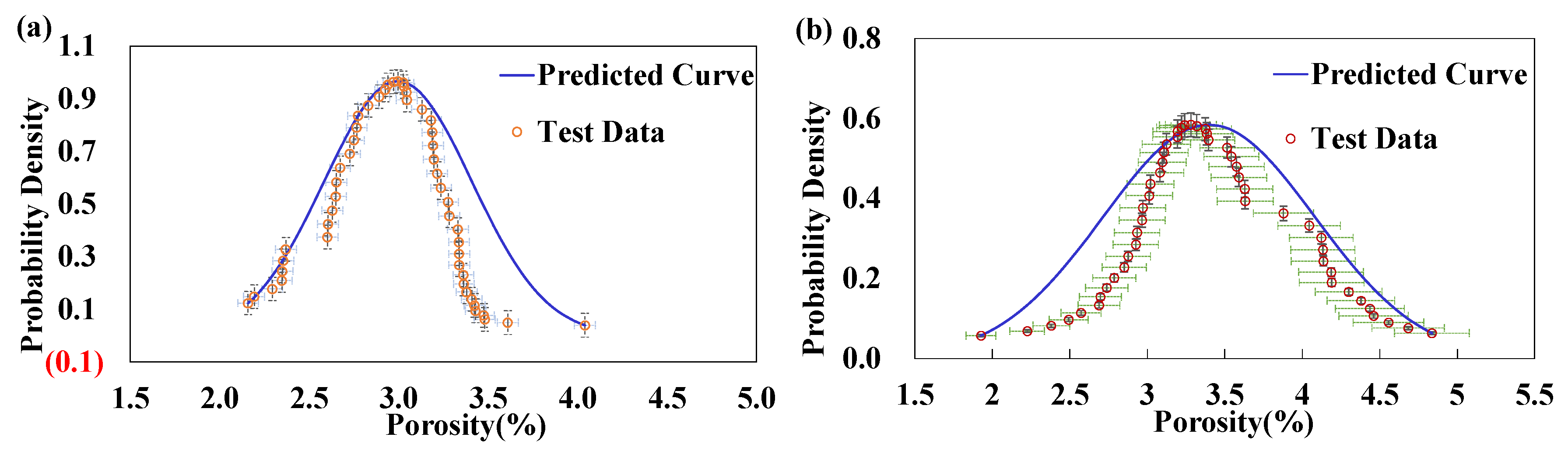
The porosity data for compression specimens and interlaminar shear specimens were utilized as samples for the calculations; the resulting normal distribution OSL values are 0.0868 and 0.0927, respectively. Furthermore, graphical methods were employed to check the normality of the samples, resulting in Pearson coefficients r of 0.9837 and 0.9883, respectively.
The analysis presented above aims to demonstrate that the porosity follows a normal distribution. Furthermore, the characteristics of this normal distribution are validated through the probability distribution curve;
Figure 9 provides a comprehensive illustration of the normality of porosity.
3.3. Effects on Mechanical Properties
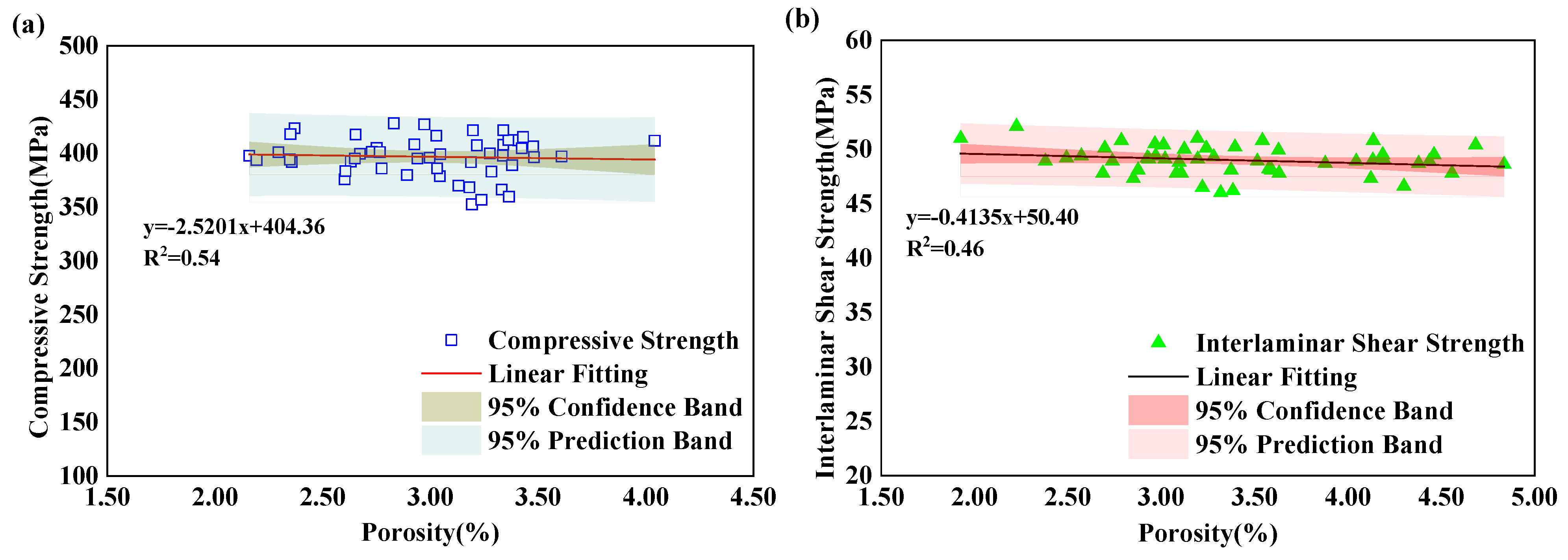
Finally, a unidirectional regression analysis was conducted to establish the relationship between mechanical properties and porosity. The compressive strength was obtained within a porosity range of 2.16% to 4.04%. According to the fitting formula, the corresponding compressive strengths are 399 MPa and 394 MPa, with a strength influence coefficient of 1.012. The interlaminar shear strength was obtained within a porosity range of 1.93% to 4.84%. According to the fitting formula, the corresponding interlaminar shear strengths are 49.6 MPa and 48.4 MPa, with a strength influence coefficient of 1.025. This information is detailed in
Figure 10, which presents a schematic diagram illustrating the relationship between porosity and strength.
According to the conclusions presented in
Section 3.2, the porosity of composite structures in certified aircraft types demonstrates a high degree of normality, indicating that the occurrence of porosity falls within a high-probability interval. This interval is narrower than the range defined by the maximum and minimum values of the sample. The strength coefficients determined previously further decrease within this high-probability interval. This suggests that, under the quality control measures implemented by the manufacturer, an increase in porosity does not significantly diminish compressive strength and interlaminar shear performance. Therefore, it can be concluded that the relatively high porosity of the composite structure in this aircraft type has a negligible effect on its mechanical properties.
3.4. Further Discussion
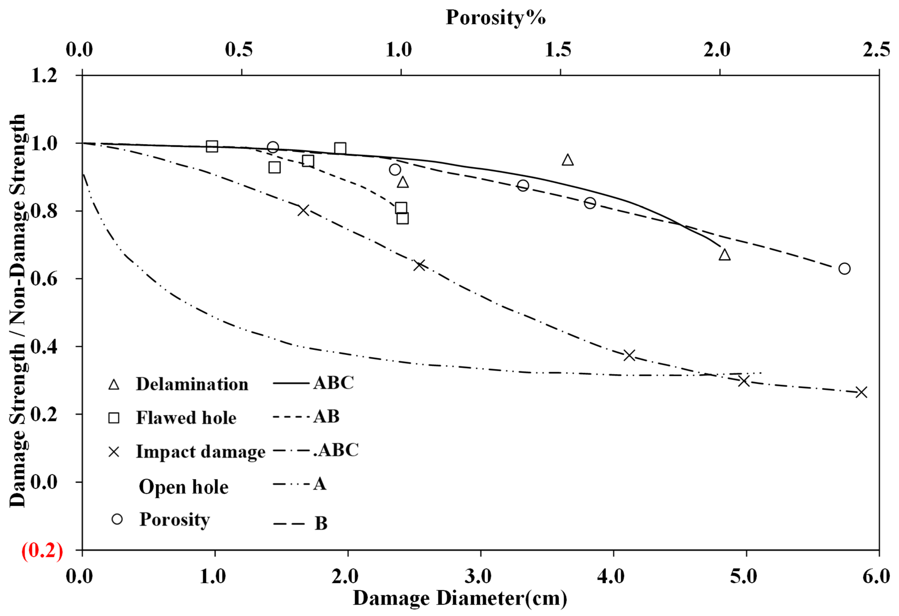
According to scholarly research on composite materials utilizing the pre-impregnated autoclave molding process, porosity significantly affects material performance [
12,
14,
16,
17]. As illustrated in
Figure 11, when porosity is below 1%, the strength remains relatively constant. However, once porosity reaches 2%, the strength decreases by approximately 20% [
22]. The statistical results from the aforementioned tests indicate that the relationship between porosity and strength in wet vacuum bagging molding specimens differs from that observed in the pre-impregnated hot press molding process. This discrepancy is preliminarily attributed to the following factors: The specimens were manufactured according to the specifications of the wet vacuum bagging molding process, which has been shown to produce components with high porosity. Porosity serves as an indicator of the overall condition of the specimen. Under conditions of high porosity, large voids can form within the specimen, and it is these substantial voids that primarily influence the specimen’s performance, rather than the porosity itself. The hypothesis regarding microstructural research mentioned above is beyond the scope of this paper.
From both theoretical and practical perspectives, porosity cannot be entirely eliminated. While it can be minimized by optimizing process parameters to enhance the structural strength of the product, it is important to consider production costs, efficiency, and the structural integrity of the components. Therefore, a certain level of porosity that does not compromise structural strength is acceptable. Additionally, non-destructive testing methods can be employed to ensure that the porosity of the parts remains within the specified range.
4. Airworthiness Method of Compliance (MoC) Recommendations
The findings of this paper reflect conclusions derived from the material selection, manufacturing conditions, and quality system of the certified aircraft type. These results do not represent those of other manufacturers in the industry that utilize the wet molding process. Consequently, the conclusions drawn from the analysis of the test results are not universally applicable, as the microscopic mechanisms by which the porosity of the wet vacuum bagging molding process influences mechanical properties have not yet been investigated. Nevertheless, the findings from the studies of the certified aircraft type can serve as a reference for verifying airworthiness compliance in similar forming processes.
The effect of porosity on the mechanical properties of composite materials is a critical consideration in structural design, manufacturing, validation, and in-service maintenance processes. Airworthiness certification requirements for aircraft composite structures stipulate that these structures must possess adequate ultimate load capacity to accommodate permissible defects. The Aircraft Structures Advisory Circular (AC20-107B) serves as the primary guidance document for airworthiness compliance methods pertaining to composite structures in civil aircraft, offering an acceptable pathway to meet aviation regulations. According to the statements in this document, the primary compliance verification related to porosity for general aircraft encompasses two main categories: Materials and processes, and static strength verification.
4.1. Materials and Processes
In accordance with the requirements outlined in the ‘Materials and Manufacturing Development’ section of the Composite Aircraft Structures Advisory Circular (AC20-107B), the composite wet hand lay-up process utilizes dry carbon fiber or glass fiber fabrics combined with resin and hardener, rather than relying on prepregs. Consequently, it is essential to establish specifications that encompass materials, material processes, and manufacturing methods. Effective measures must be implemented to minimize porosity and the coefficient of variation, enhance material stability, and ensure the production of consistent and reliable structures. This also serves as the foundation for investigating the relationship between porosity and mechanical properties.
Specific implementation methods include establishing material specifications for carbon fiber or glass fiber dry fabrics, resins, curing agents, and post-impregnation processes to ensure material consistency. It is crucial to define inspection batches, sampling plans, and inspection frequencies rigorously. Additionally, monitoring critical characteristics and process parameters is essential, including the control of resins and curing agents, as well as precise management of mixing ratios and quality. Controlling resin content during post-impregnation, along with strict adherence to operating procedures by impregnation and lay-up technicians, is equally vital to ensure consistent material performance.
4.2. Static Strength Verification of Structures
The wet lay-up molding process for composite structures introduces significant material and process variability, primarily resulting in relatively high porosity and variability exceeding 10% within a specific range. This variability, which surpasses 10%, has not been adequately addressed in static strength verification and fails to meet the requirements outlined in Section 7e of AC20-107B. Specifically, the overload factor applied must be validated through testing or prior experience and should account for anticipated material and process variability [
23]. In accordance with the static strength verification requirements for airworthiness verification of aircraft composite structures [
24], it is essential to ensure that the ultimate load capacity of acceptable defects is included in the design criteria [
25]. It is recommended to address the issue of high porosity through the following methods.
Appropriate overload can be incorporated during static strength verification to cover the effects of porosity. To ensure structural safety, it is essential to consider the strength reduction caused by porosity if it affects the critical mechanical properties of the structures. Consequently, when assessing the static strength of the structure, an additional overload factor should be applied to account for the strength reduction associated with high porosity, thereby ensuring the ultimate load capacity remains acceptable despite the presence of void defects. The applied overload factor must receive approval from a qualified certification authority.
If porosity influences mechanical properties, the additional overload factor introduced during testing must be determined using the following method. First, obtain the mechanical properties (such as compressive strength or interlaminar shear strength) and porosity from the same specimen. Next, establish a reasonable testing sequence and statistically analyze the porosity using standard distribution methods. Determine the high-probability range of porosity and fit the porosity and mechanical property data to establish a correlation. Subsequently, calculate the upper and lower limits of the mechanical properties within the high-probability interval. Determine the load coefficient based on the ratio of the upper and lower limits, and apply this load factor to the original load condition to establish a new load condition. Finally, apply the new load condition in static strength tests to complete the airworthiness compliance verification.
For composite structures, fatigue is typically addressed in a static context. However, for wet vacuum bagging composite structures, it is crucial to concentrate on identifying defects or damage. Future work may also benefit from integrating structural health monitoring techniques such as back face strain (BFS) or zero-strain point (ZSP) analysis, which have demonstrated sensitivity to crack initiation and progression in composite joints under various loading scenarios [
26]. These approaches could enhance compliance verification, especially for hand-layup structures where in-process variability is higher.


