Article

Launch Experiment of Microwave Rocket Equipped with Six-Staged Reed Valve Air-Breathing System

1
Department of Aeronautics and Astronautics, School of Engineering, The University of Tokyo, 7-3-1 Hongo, Tokyo 113-8656, Japan
2
National Institute for Quantum Science and Technology, 801-1 Mukoyama, Naka 311-0193, Japan
3
Department of Mechanical Engineering, Faculty of Science and Engineering, Setsunan University, 17-8 Ikedanakamachi, Neyagawa 572-8508, Japan
*
Author to whom correspondence should be addressed.
Aerospace 2025, 12(7), 577; https://doi.org/10.3390/aerospace12070577
Submission received: 29 May 2025 / Revised: 20 June 2025 / Accepted: 23 June 2025 / Published: 25 June 2025
(This article belongs to the Special Issue Advances in Detonative Propulsion (2nd Edition))

Abstract

Millimeter-wave-supported detonation (MSD) is a unique detonation phenomenon driven by a supersonically propagating ionization front, sustained by intense millimeter-wave beams. Microwave Rocket, which utilizes MSD to generate thrust from atmospheric air in a pulse detonation engine (PDE) cycle, is a promising low-cost alternative to conventional chemical propulsion systems for space transportation. However, insufficient air intake during repetitive PDE cycles has limited achievable thrust performance. To address this issue, a model equipped with a six-stage reed valve system (36 valves in total) was developed to ensure sufficient air intake, which measured 500 mm in length, 28 mm in radius, and 539 g in weight. Launch demonstration experiments were conducted using a 170 GHz, 550 kW gyrotron developed at the National Institutes for Quantum Science and Technology (QST). Continuous thrust was successfully generated by irradiating up to 50 pulses per experiment at each frequency between 75 and 150 Hz, in 25 Hz increments, corresponding duty cycles ranging from 0.09 to 0.18. A maximum thrust of 9.56 N and a momentum coupling coefficient C m of 116 N/MW were obtained. These values represent a fourfold increase compared to previous launch experiments without reed valves, thereby demonstrating the effectiveness of the reed valve configuration in enhancing thrust performance.

1. Introduction

Beyond curiosity, interest in space for the exploitation of space resources, defense, and medical purposes has never been higher. Despite chemical rocket propulsion’s complex and costly components, such as turbopumps, chemical rocket vehicles are typically single-use, resulting in high operational costs. Furthermore, the specific impulse, the key parameter of propulsion efficiency, has nearly reached its theoretical limit, leaving little room for significant performance improvement. To enable low-cost space transportation, not only has vehicle performance been improved, but also reusable vehicles have been developed and operated. However, these vehicles still have the same problem of carrying a significant amount of propellant mass on board. So, as one of the fundamental solutions, beamed energy propulsion (BEP) has been studied. Being different from chemical propulsion, BEP is a system in which energy can be supplied to the vehicle from the outside in the form of an electromagnetic wave beam to generate thrust. Various BEP-based propulsion systems have been studied [1,2,3,4,5]. Myrabo developed Lightcraft [6], which is a multi-pulse detonation engine (PDE) system powered by a pulsed CO2 laser, and recorded the momentum coupling coefficient C m of 160 N/MW, which is the ratio of the generated impulse to the input energy, under the multi-pulse conditions.
One of the other PDE-type beamed propulsion systems is Microwave Rocket. It uses pulsed millimeter waves as its energy source and generates thrust by millimeter-wave-supported detonation (MSD) [7,8,9,10,11,12,13,14,15,16,17,18]. Microwave Rocket is expected to offer low-cost launch for the following three reasons: (1) The use of the atmosphere as propellant eliminates the onboard propellants and enables a high payload ratio. (2) The millimeter-wave oscillator base is reusable and thus depreciable. (3) Unlike conventional liquid propellant rocket engines, a turbo-pump propellant feed mechanism is not required, enabling a significant reduction in the vehicle production cost.
As illustrated in Figure 1, Microwave Rocket consists of a parabolic nose with a focusing mirror for plasma ignition, a cylindrical detonation tube, and a reed valve air-breathing system. The four-step PDE cycle of Microwave Rocket is also shown in the figure: (1) Millimeter-wave is injected into Microwave Rocket and focused at the forcusing mirror, causing air breakdown. (2) Plasma absorbs millimeter-wave energy and propagates supersonically with a shockwave (MSD). (3) Shockwave reaches Microwave Rocket’s open end, and the expansion wave propagates in Microwave Rocket. (4) Reed valves open and air is refilled because of the negative pressure in the thruster against the environment (Return to (1)).
Like chemical-fueled PDE, the performance of Microwave Rocket deteriorates due to the residual low-density gas within the detonation tube. Previous studies have demonstrated that the impulses generated after the second pulse are influenced by the partial filling rate (PFR), defined as the ratio of air intake volume to the total thruster volume [19]. To address this issue, reed valves were introduced into Microwave Rocket as an air-breathing system. These valves have a simple structure, passively opening in response to the pressure inside the detonation tube, allowing air to refill accordingly.
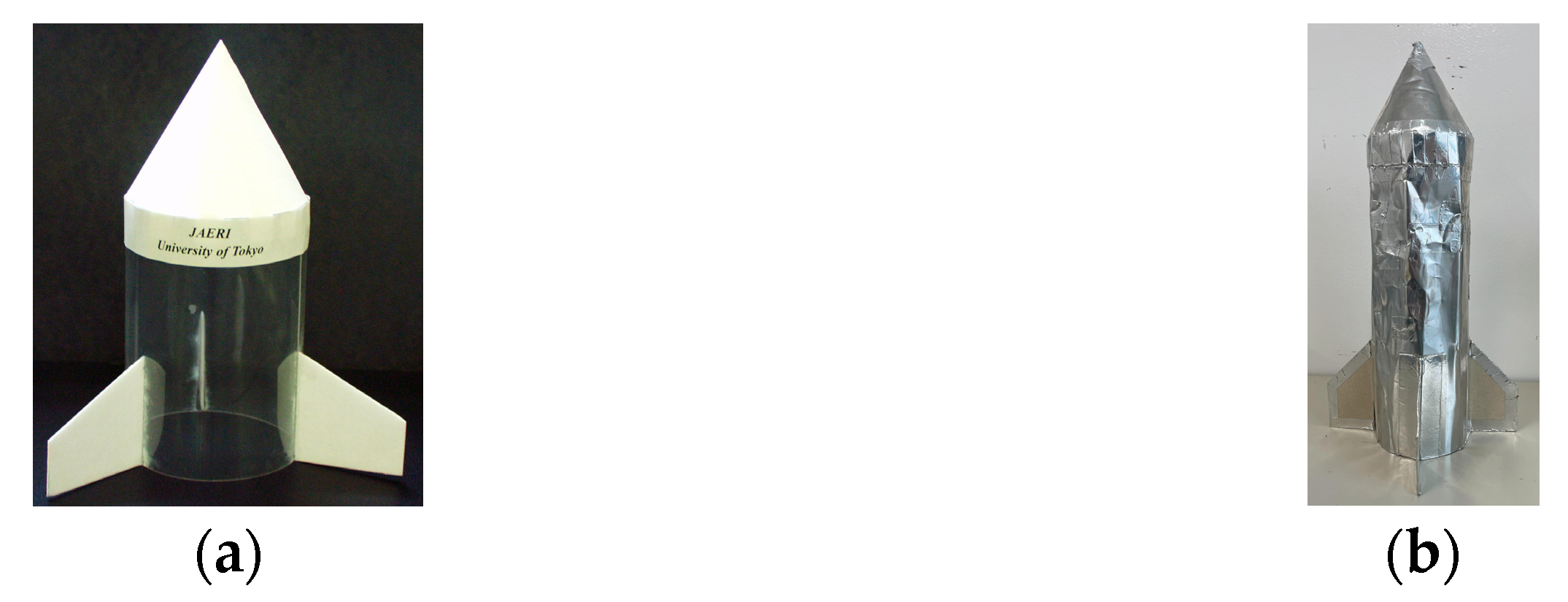
A single-pulse launch experiment of Microwave Rocket was conducted in 2003 [12] for the first time using a 1 MW class millimeter-wave generator, a gyrotron, developed by the National Institutes of Quantum Science Technology (QST). The rocket model was shaped as shown in Figure 2a, which was made of plastic, having a nose with aluminum foil attached to its backside and no air-intake system. Its single-pulse flight was filmed by a high-speed camera, and C m was estimated at 395 N/MW. A multi-pulse launch experiment was conducted in 2009 [19] using a longer and heavier rocket model than the above model, as shown in Figure 2b, in which aluminum foils were laminated to cardboard. As a result, the time-averaged thrust and C m for these models were estimated to be 2.32 N and 30.9 N/MW, respectively. Both model specifications and experimental parameters are listed in Table 1, while the experimental results are summarized in Table 2.
It was anticipated that the fresh air refill would mitigate the adverse effects of residual low-density gases. Therefore, launch experiments of Microwave Rocket with titanium reed valves as an air intake system were conducted in 2012 [20]. However, the launch was unsuccessful due to lower-than-expected thrust. This was thought to be because the plasma ignited anomalously in the middle of the detonation tube due to the electric field concentration at the tip of the titanium reed valves. Therefore, in this study, plastic reed valves were used to demonstrate the effectiveness of the reed-valve air intake and to show their practical applicability to actual flight. The dynamics of the plastic reed valves, pressure recovery curves, and resulting partial filling rate had been investigated in ground-static experiments prior to this study [21].

2. Reed Valve Design

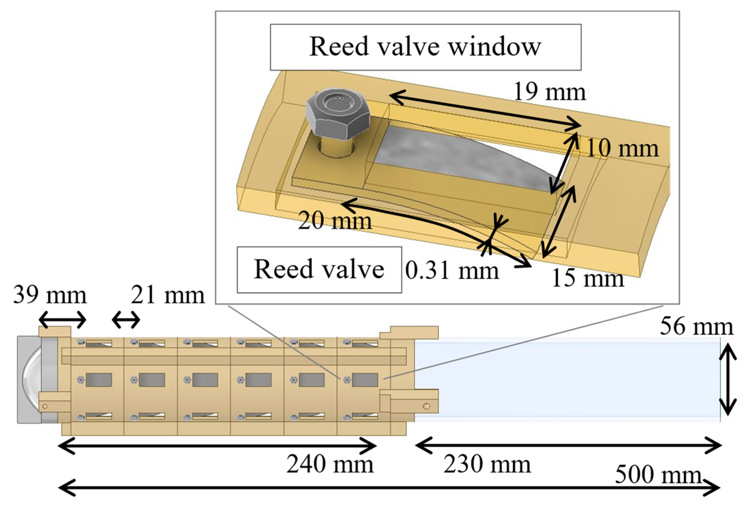
In this launch experiment, glass fiber-reinforced plastic (GFRP) was employed as the material for the reed valves to prevent anomalous discharge, with a fundamental frequency of 384 Hz. The characteristics of the reed valves are summarized in Table 3. The static tip displacement refers to the deformation of the reed valve under a representative negative gauge pressure of 0.35 atm. The model design and reed valve geometry are shown in Figure 3. The rocket model is composed of a nose and a detonation tube, which has an opaque part with valves and a transparent part without valves. The nose has a metal parabolic mirror inside, whose focal length is 10 mm, to ignite plasma. The tube has an inner diameter of 56 mm, and its untransparent part is made of Poly-Lactic Acid (PLA) plastic, while the transparent part is made of acrylic. In the first stage, the upper edge of the reed valve was positioned approximately 39 mm from the focal point. The axial distance between the following reed valve stages was 21 mm, and the flow passage window for each valve was 10 × 19 mm. Six stages of reed valves were installed, with each stage containing six reed valves equally spaced in the circumferential direction (36 valves in total). This corresponds to an intake area coverage of approximately 30% of the model diameter. In the axial direction, the reed valves were installed from the top to 240 mm, and the total area occupied by the valve windows accounted for 6.8% of the model’s surface area. This configuration was based on previous CFD studies [22], in which negative gauge pressure appeared in approximately the top 48% of the thruster tube.

3. Setup for Launch Experiment

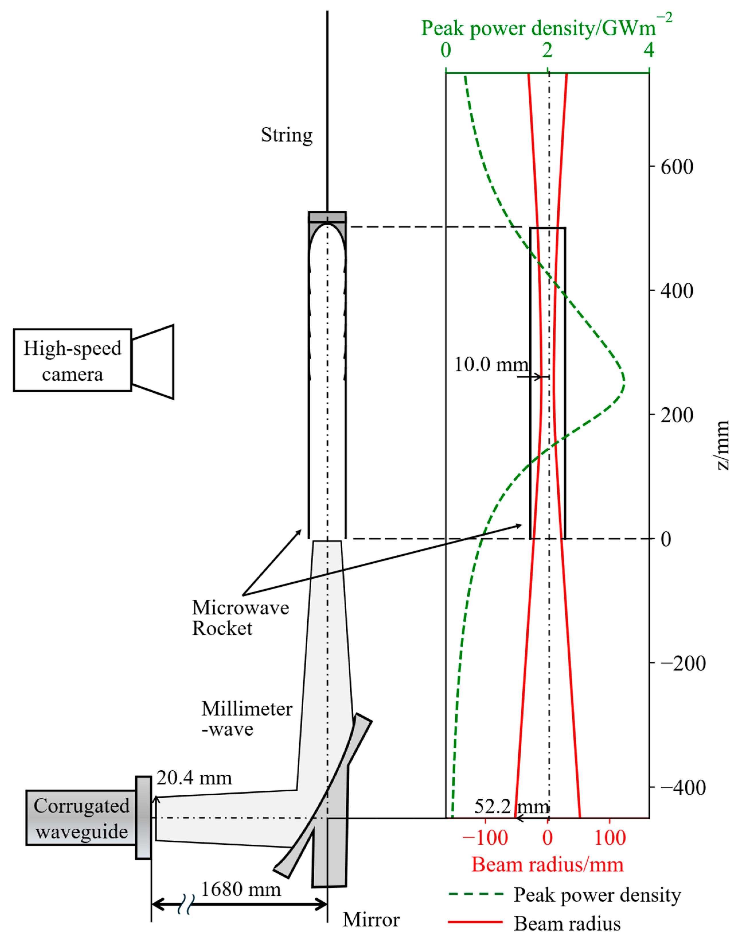
The experimental parameters are shown in Table 4. The experimental setup, the beam shape, and its power density are shown in Figure 4. The millimeter-wave frequency and the output power from the gyrotron were set at 170 GHz and 550 kW, respectively. A millimeter-wave beam was formed by using a single existing concave mirror just for the reed valve performance evaluation. The collimation mirror was placed far from the waveguide to prevent the plasma from contacting the sapphire window of the waveguide. However, this resulted in a relatively large beam diameter at the mirror and required beam focusing from the mirror to the rocket model, as shown in Figure 4. The focal point was located 252 mm from the bottom of the model, approximately at its geometric center. The focal length of the mirror differs in the vertical and horizontal directions, resulting in an elliptical beam cross-section. Therefore, the beam radius was plotted using an equivalent radius, which explains the asymmetrical power density distribution in the figure. Due to its narrow beam waist, the beam radius and power density varied significantly with height; however, millimeter-wave energy spilling from the tube was minimized by setting the initial position of the model at 500 mm above the mirror by a string.
The millimeter-wave pulse duration was fixed at 1.2 ms based on the previous static discharge data, and the pulse repetition frequency varied between 75 and 150 Hz. A high-speed camera (FASTCAM NOVA S6 type 800K-M/C 16 GB, Photron, Toyko, Japan) was used to capture images of the model in flight at 10,000 FPS, and the thrust was calculated from the trajectory of the model.

4. Results and Discussion

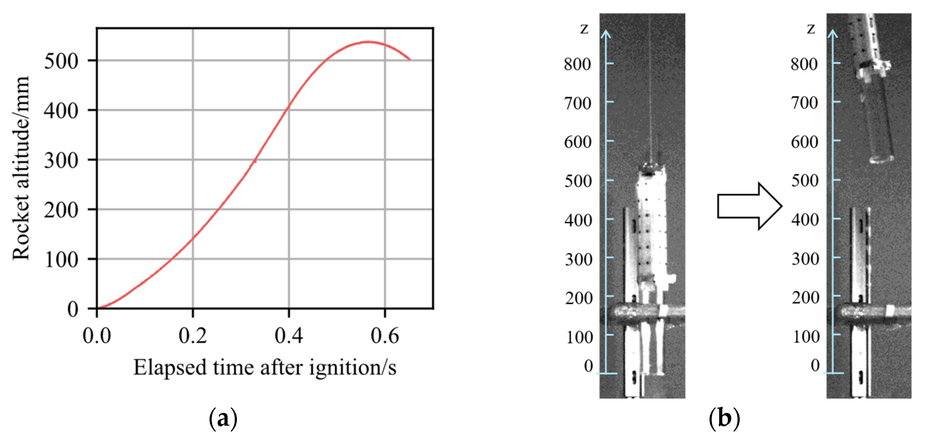
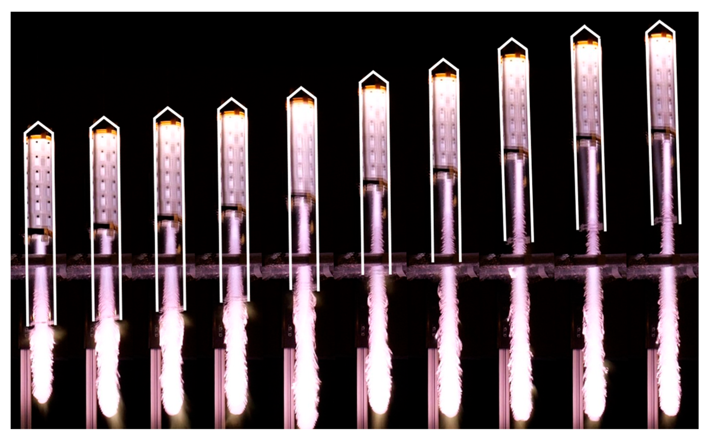
Only those experiments with at least 20 pulses without misfire were considered successful and representative enough for further evaluation. Misfire was attributed to gyrotron oscillation instability caused by reflections of millimeter waves by plasma generated in the rocket model or by arcing inside the gyrotron. The reflections decrease with the beam transfer distance, and arcing is reduced by the baking operation of the gyrotron in general. Therefore, the analysis focuses on 14 launches (one at 75 Hz, five at 100 Hz, three at 125 Hz, and five at 150 Hz). The altitude was limited due to the diverging beam profile shown in Figure 4; however, the issue will be mitigated in the future by designing suitable beam optics. The highest altitude of approximately 500 mm was achieved with 43 pulse injections at 100 Hz pulse repetition frequency, and its trajectory and flight footage are shown in Figure 5.
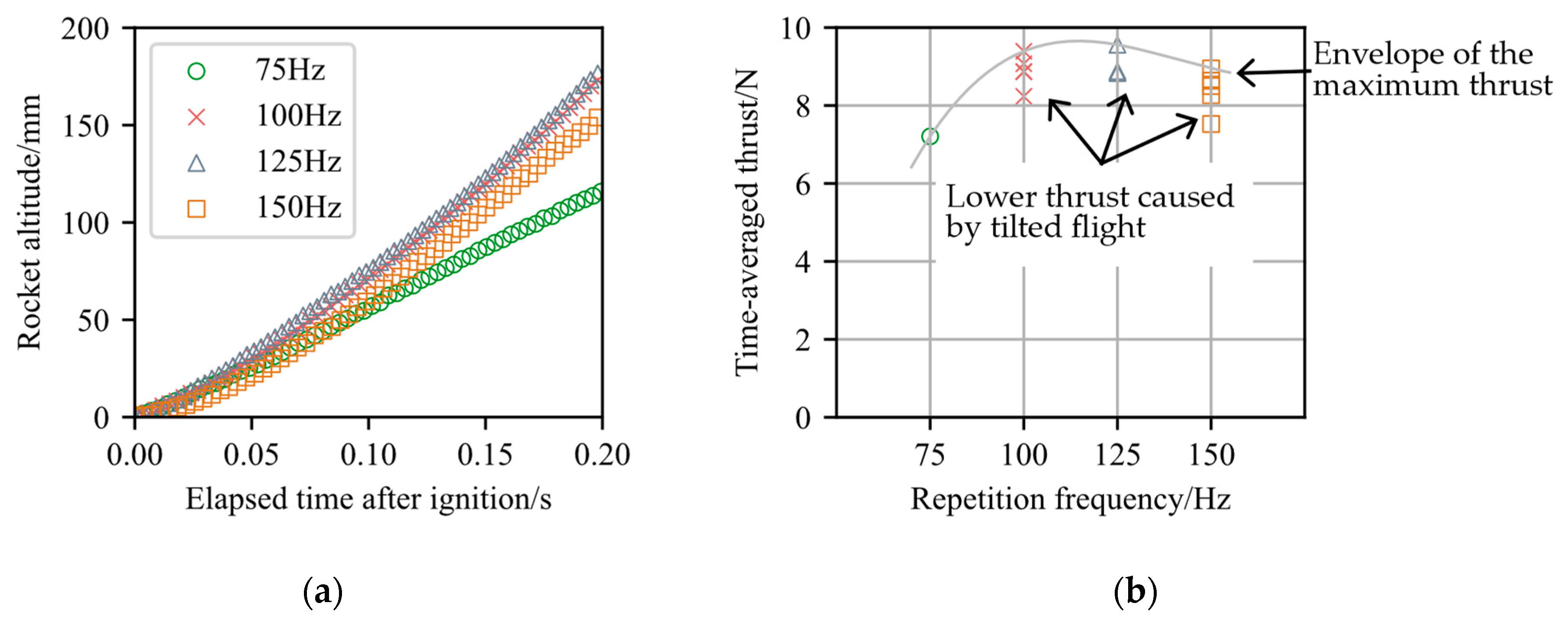
The flight data yielding the highest time-averaged thrust is selected and plotted in Figure 6, together with the corresponding time-averaged thrust values calculated from these trajectories. The maximum C m was obtained when the rocket model was properly aligned with the millimeter-wave beam. The solid curve in Figure 6b represents an envelope of the maximum values, and in other flights, thrust was lower because of the tilted flight. The maximum time-averaged thrust of 9.56 N was obtained at the pulse repetition frequency of 125 Hz, and the corresponding C m was 116 N/MW. The correlation between the time-averaged thrust and the pulse repetition frequency was as expected from a previous study [21].
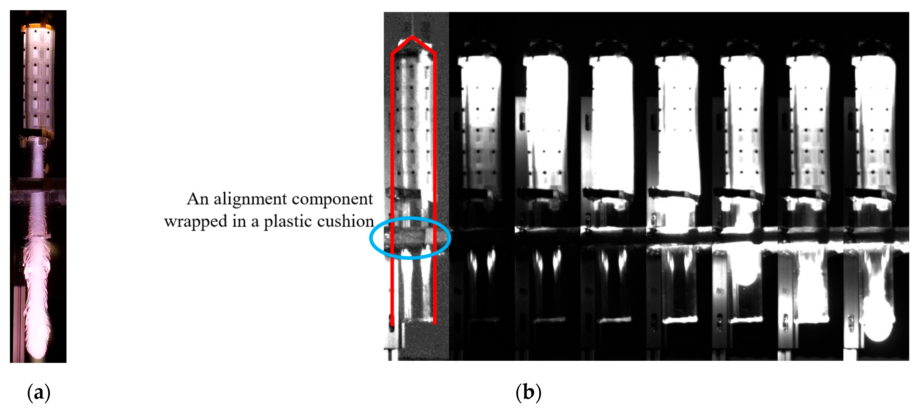
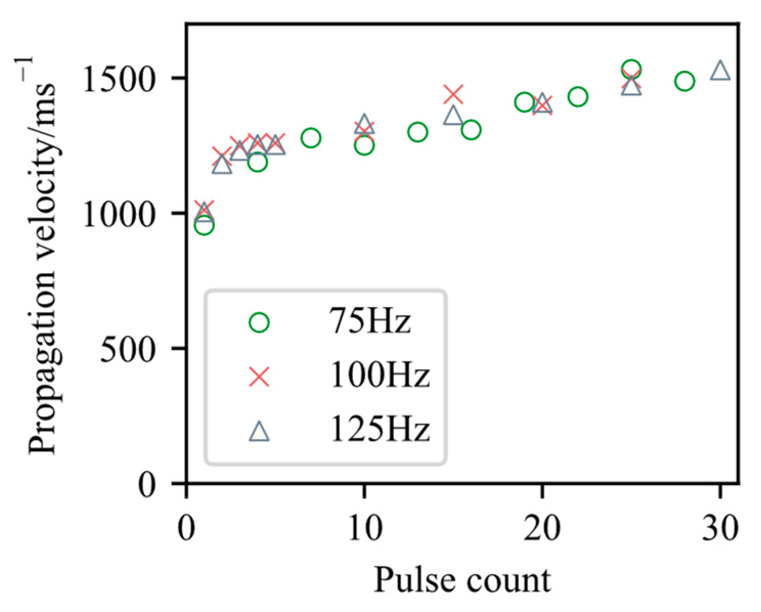
The self-emission photographs of millimeter-wave discharge plasma are shown in Figure 7, and propagation velocity U i of the discharge front is plotted in Figure 8. Figure 7 depicts an alignment component wrapped in plastic cushioning, which serves to protect it from potential contact with the model post-launch. This cushioning reflects plasma light, and similarly, the model’s lower end also glows, an effect attributed to refractive index changes resulting from thermal melting. Furthermore, the model’s upper end remained bright because of residual plasma. The measured U i was 980 m/s ± 30 m / s at the first pulse. It showed a good agreement with the following relationship between propagation velocity U i [m/s] and beam power density S b [GW/m2] measured in the previous study [23].
U i = 419 S b 14.7
The velocity obtained from Equation (1) was 976 m/s at the power density of 2.36 GW/m, which was averaged from z = 0 mm to 500 mm.
The increase in U i as the pulse count progresses is due to the increase in low-density residual gas in the model as reported in the literature [24]. The difference in propagation velocity across repetition frequencies was not significant. This is because even at 75 Hz, the longest intake duration, the density recovery by the designed reed valves had already reached its limit, and this suggests that there is room for further improvement in reed valve design.
All the results of launch experiments were summarized in Table 5. The C m of this experiment corresponds to approximately 400% of the multi-pulse launch without a reed valve, though only 75% of the value observed in Lightcraft.
As observed in Figure 7a, the ratio of plasma length to the model length l was as large as 2.2, which was larger than the optimum value of 0.6–0.8 [13], resulting in poorer C m than expected. This was because the beam waist was smaller than the tube radius, resulting in a higher-than-anticipated propagation velocity of the discharge front. To address this issue, in the next experiment, it is essential to design an optical system that produces a parallel beam. Simultaneously, the plasma length will be monitored in real time, and the pulse duration should be adjusted to maintain a plasma length ratio of 0.8. This approach is expected to enable pulse shortening, enhance air intake from the open end, improve thrust performance, and reduce the required input power.
Additionally, Figure 9 shows the plasma in the case when the model was set tilted, attributed to mass asymmetry and an offset in the string’s suspension point. In future experiments, this tilt must be eliminated.

5. Conclusions

Using the gyrotron developed by the National Institutes of Quantum Science and Technology, a 539 g Microwave Rocket was successfully launched in multiple experiments, reaching a maximum flight altitude of approximately 500 mm with 43 pulse irradiations. A dependence of thrust performance on the pulse repetition frequency was observed during this process. With the designed model equipped with reed valves, a maximum time-averaged thrust of 9.56 N and a momentum coupling coefficient C m of 116 N/MW were achieved at 125 Hz pulse repetition frequency. This C m corresponds to approximately 400% of that achieved in previous multi-pulse operation without a reed valve.
While both Microwave Rocket and laser-boosted vehicles achieve comparable C m levels in single-pulse operation [12], Microwave Rocket’s C m currently stands at only 75% of Lightcraft’ C m in multi-pulse operation. This performance gap suggests considerable room for improvement, attainable through optimization across three areas: reed valve design, the optical system, and operational parameters. Future efforts will focus on refining the reed valve design, exploring the impact of its fundamental frequency, length, width, orientation, position, and valve area coverage on overall performance. Concurrently, the optical system will be improved to minimize energy loss from beam divergence and non-uniform breakdown. A comprehensive analysis of energy distribution, encompassing reflection losses, plasma heating efficiency, and expansion losses, will guide these optical improvements. Furthermore, operational parameters and setup will be refined, specifically by a new launch stand and precisely tuning the pulse duration to maintain the plasma length within 60–80% of the tube’s total length, which is crucial for optimizing energy coupling and thrust generation.

Author Contributions

Conceptualization, K.I. (Kosuke Irie), A.M., and K.K. (Kimiya Komurasaki); data curation, K.I. (Kosuke Irie) and A.M.; formal analysis, K.I. (Kosuke Irie); funding acquisition, A.M. and K.K. (Kimiya Komurasaki); investigation, K.I. (Kosuke Irie), A.M., T.N. (Tomonori Nakatani), T.N. (Toshinobu Nomura), and Y.O.; methodology, K.I. (Kosuke Irie), A.M., T.N. (Tomonori Nakatani), T.K., M.W., K.K. (Kimiya Komurasaki), and Y.O.; project administration, A.M. and K.K. (Kimiya Komurasaki); resources, T.S., R.I., K.I. (Keito Ishita), T.N. (Taku Nakai), and K.K. (Ken Kajiwara); software, K.I. (Kosuke Irie); supervision, K.K. (Kimiya Komurasaki); validation, A.M.; visualization, K.I. (Kosuke Irie); writing—original draft, K.I. (Kosuke Irie); writing—review and editing, K.I. (Kosuke Irie), A.M., T.N. (Tomonori Nakatani), T.K., T.N. (Toshinobu Nomura), M.W., K.K. (Kimiya Komurasaki), T.S., R.I., K.I. (Keito Ishita), T.N. (Taku Nakai), K.K. (Ken Kajiwara), and Y.O. All authors have read and agreed to the published version of the manuscript.

Funding

This work was supported by JSPS KAKENHI Grant Numbers 20H02344 and 24KJ0564.

Data Availability Statement

The data that support the findings of this study are available from the corresponding author upon reasonable request.

Conflicts of Interest

The authors declare no conflicts of interest.

References

  1. Pakhomov, A.V.; Thompson, M.S.; Swift, W.; Gregory, D.A. Ablative Laser Propulsion: Specific Impulse and Thrust Derived from Force Measurements. AIAA 2002, 40, 2305–2311. [Google Scholar] [CrossRef]
  2. Phipps, C.; Luke, J. Diode Laser-Driven Microthrusters: A New Departure for Micropropulsion. AIAA 2002, 40, 310–318. [Google Scholar] [CrossRef]
  3. Kare, J.T. Laser-powered heat exchanger rocket for ground-to-orbit launch. J. Propul. Power 1995, 11, 535–543. [Google Scholar] [CrossRef]
  4. Eguchi, K.; Tuan, T.D.; Ymamori, H.; Mori, K. Continuous-wave Laser Propulsion Using a Porous Carbon Heat Exchanger. Aerosp. Technol. Jpn. 2018, 17, 285–288. [Google Scholar]
  5. Parkin, K.L.; Murakami, D.D. In 48th AIAA/ASME/SAE/ASEE Joint Propulsion Conference Exhibit; AIAA: Atlanta, GA, USA, 2012. [Google Scholar]
  6. Myrabo, L.N. Brief History of the Lightcraft Technology Demonstrator (LTD) Project. AIP Conf. Proc. 2003, 664, 49–60. [Google Scholar]
  7. Komurasaki, K.; Shimamura, K.; Fukunari, M.; Oda, Y.; Imai, T.; Takahashi, M.; Katsurayama, H.; Ohnishi, N. Microwave rocket propelled by millimeter wave. J. Plasma Fusion Res. 2017, 93, 465–466. [Google Scholar]
  8. Komurasaki, K.; Tabata, K. Development of a Novel Launch System Microwave Rocket Powered by Millimeter-Wave Discharge. Int. J. Aerosp. Eng. 2018, 2018, 1–9. [Google Scholar] [CrossRef]
  9. Batanov, G.M.; Gritsinin, S.I.; Kossyy, I.A.; Magunov, A.N.; Silakov, V.P.; Tarasova, N.M. High-pressure microwave discharges. In Subthreshold Discharge Excited by Microwave Beam in the High-Pressure GASES; Physics and Applications, Pero, Ltd.: Moscow, Russia, 2019; pp. 6–35. [Google Scholar]
  10. Shimamura, K.; Matsukura, M.; Ozaki, N.; Miyawaki, K.; Yokota, S.; Minami, R.; Kariya, T.; Imai, T. Wireless Power Transmission Efficiency for Microwave Rocket Using 28 GHz Gyrotron. J. Spacecr. Rocket. 2020, 57, 632–635. [Google Scholar] [CrossRef]
  11. Takahashi, M.; Ohnishi, N. Numerical study of discharge and thrust generation in a microwave rocket. In Proceedings of the AIAA Scitech 2019 Forum, San Diego, CA, USA, 7–11 January 2019. [Google Scholar] [CrossRef]
  12. Nakagawa, T.; Mihara, Y.; Komurasaki, K.; Takahashi, K.; Sakamoto, K.; Imai, T. Propulsive Impulse Measurement of a Microwave-Boosted Vehicle in the Atmosphere. J. Spacecr. Rocket. 2004, 41, 151–153. [Google Scholar] [CrossRef]
  13. Oda, Y.; Komurasaki, K.; Takahashi, K.; Kasugai, A.; Sakamoto, K. Plasma generation using high-power millimeter-wave beam and its application for thrust generation. J. Appl. Phys. 2006, 100, 113307. [Google Scholar] [CrossRef]
  14. Komatsu, R.; Ymaguchi, T.; Oda, Y.; Saito, S.; Fukunari, M.; Komurasaki, K.; Ken, K.; Takahashi, K.; Sakamoto, K. Thrust Enhancement of Microwave Rocket via High-Power, High-Duty-Cycle Operation. J. JPN. Soc. Aeronaut. Space Sci. 2012, 60, 235–237. [Google Scholar]
  15. Fukunari, M.; Komurasaki, K.; Nakamura, Y.; Oda, Y.; Sakamoto, K. Rocket Propulsion Powered Using a Gyrotron. J. Energy Power Eng. 2017, 11, 363–371. [Google Scholar]
  16. Fukunari, M.; Arnault, A.; Yamaguchi, T.; Komurasaki, K. Replacement of chemical rocket launchers by beamed energy propulsion. Appl. Opt. 2014, 53, I16–I22. [Google Scholar] [CrossRef]
  17. Kakinuma, K.; Fukunari, M.; Yamaguchi, T.; Nakamura, Y.; Koizumi, H.; Komurasaki, K.; Parkin, K. Two-Stage-to-Orbit Transporting System Combining Microwave Rocket and Microwave Thermal Rocket for Small Satellite Launch. Trans. Jpn. Soc. Aeronaut. Space Sci. Aerosp. Technol. Jpn. 2016, 14, Pb99–Pb103. [Google Scholar] [CrossRef]
  18. Taniguchi, T.; Yabata, K.; Manabe, A.; Tamagawa, T.; Komurasaki, K.; Koizumi, H. Investigation of Transmission Frequency and Optical System Design for Cost-Effective Launch of Microwave Rockets. Space Sol. Power Syst. 2021, 6, 51–58. [Google Scholar]
  19. Oda, Y.; Shibata, T.; Komurasaki, K.; Takahashi, K.; Kasugai, A.; Sakamoto, K. Thrust Performance of Microwave Rocket Under Repetitive-Pulse Operation. J. Propuls. Power 2009, 25, 118–122. [Google Scholar] [CrossRef]
  20. Fukunari, M.; Yamaguchi, T.; Nakamura, Y.; Komurasaki, K.; Oda, Y.; Kajiwara, K.; Takahashi, K.; Sakamoto, K. Thrust generation experiments on microwave rocket with a beam concentrator for long distance wireless power feeding. Acta Astronaut. 2018, 145, 263–267. [Google Scholar] [CrossRef]
  21. Manabe, A.; Irie, K.; Nakatani, T.; Kinoshita, T.; Nomura, T.; Weiand, M.; Komurasaki, K.; Shinya, T.; Ikeda, R.; Ishita, K.; et al. Experimental evaluation of a reed valve air intake system for microwave rocket in ground-static tests. Acta Astronaut. 2025, 234, 410–418. [Google Scholar] [CrossRef]
  22. Fukunari, M.; Yamaguchi, T.; Komurasaki, K.; Oda, Y.; Ikeda, R.; Kajiwara, K.; Takahashi, K.; Sakamoto, K. Air-breathing system using reed valve for pulse detonation microwave rocket. Trans. Jpn. Soc. Aeronaut. Space Sci. Aerosp. Technol. Jpn. 2016, 14, 1–7. [Google Scholar] [CrossRef]
  23. Shimada, Y.; Shibata, T.; Yamaguchi, T.; Oda, Y.; Kajiwara, K.; Takahashi, K.; Kasugai, A.; Sakamoto, K.; Komurasaki, K.; Arakawa, Y.; et al. Propagating structure of a microwave driven shock wave inside a tube. AIP Conf. Proceedings. Am. Inst. Phys. 2010, 1230, 366–376. [Google Scholar]
  24. Oda, Y.; Komurasaki, K.; Takahashi, K.; Kasugai, A.; Sakamoto, K. Investigation of Microwave Rocket Propulsion Performance under Varying Atmospheric Pressures with a High-Power Gyrotron. J. Plasma Fusion Res. 2007, 83, 296–299. [Google Scholar]
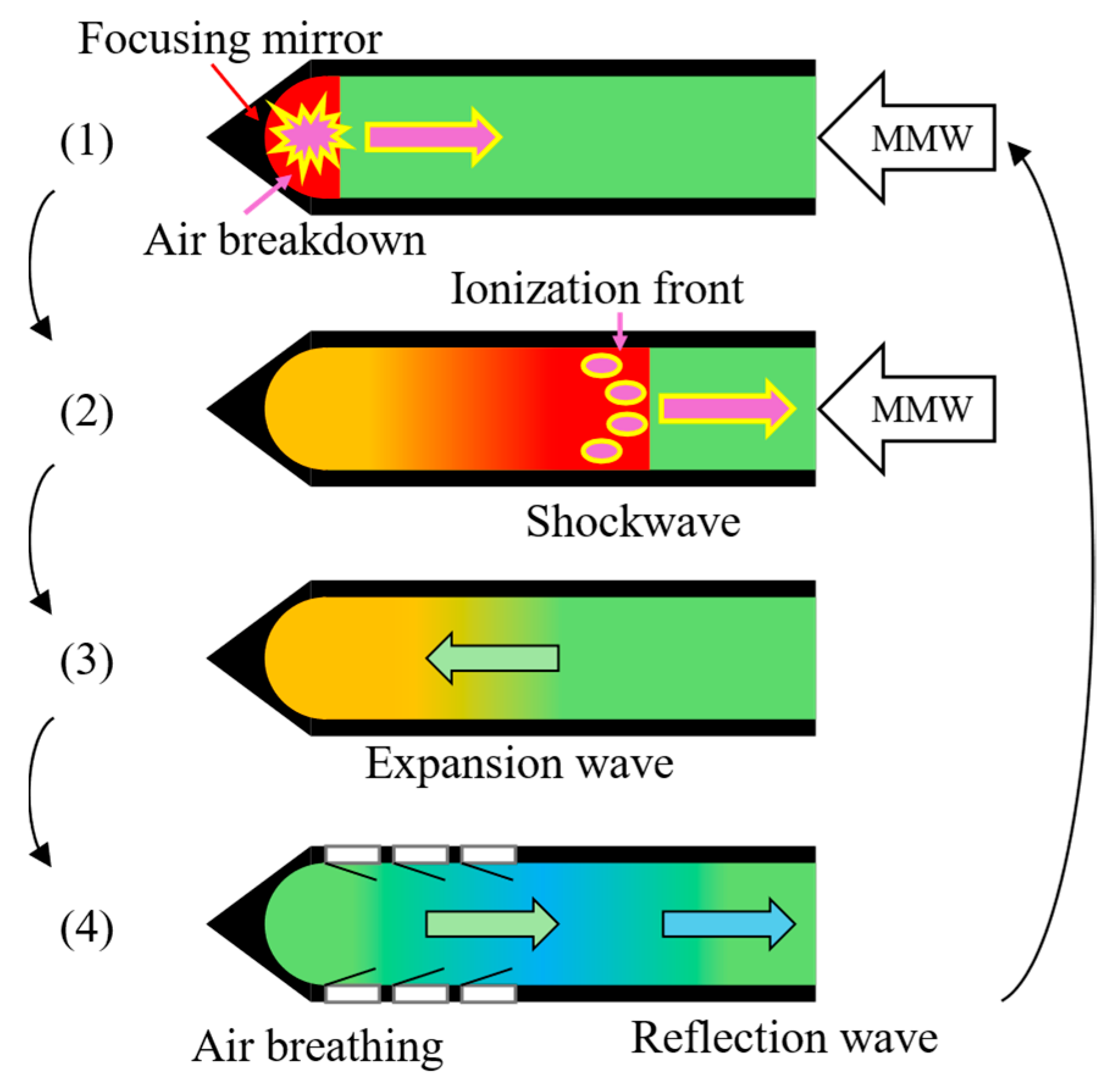
Figure 1. Microwave Rocket PDE cycle.: (1) air breakdown; (2) propagation of MSD; (3) propagation of the expansion wave; (4) Air-breathing through reed valves.
Aerospace 12 00577 g001
Figure 2. Microwave Rocket models: (a) for single-pulse operation in 2003 [12]; (b) for multi-pulse operation in 2009 [19].
Aerospace 12 00577 g002
Figure 3. The rocket model design and reed valve geometry.
Aerospace 12 00577 g003
Figure 4. Launch experimental setup.
Aerospace 12 00577 g004
Figure 5. Experimental result at the maximum altitude: (a) trajectory; (b) flight footage.
Aerospace 12 00577 g005
Figure 6. Experimental results: (a) rocket model trajectory; (b) time-averaged thrust at different pulse repetition frequencies.
Aerospace 12 00577 g006
Figure 7. Rocket model and millimeter-wave discharge plasma: (a) long exposure photography; (b) high-speed camera footage (10,000 FPS).
Aerospace 12 00577 g007
Figure 8. Plasma propagation velocity at the various repetition frequencies.
Aerospace 12 00577 g008
Figure 9. The photos of the model and plasma when the model was tilted.
Aerospace 12 00577 g009
Table 1. Rocket models and experimental parameters in previous launches (2003 and 2009).
Parameters Single-Pulse Operation [12]Multi-Pulse Operation [19]
Model mass [g]19.5109
Model size diameter × length [mm]⌀66 × 177⌀100 × 380
RF beam power [kW] 1000 600
Millimeter-wave frequency [GHz]110170
Pulse duration [ms]0.1751.25
Pulse repetition frequency [Hz]-100
Table 2. Results of previous launches (2003 and 2009).
Parameters Single-Pulse [12]Multi-Pulse [19]
Altitude [m]1.22.0
Thrust impulse [Ns] or Time-averaged thrust [N]0.0692.32
Momentum coupling coefficient [N/MW]39530.9
Table 3. Designed reed valve parameters.
ParametersValues
Reed valve dimensionsLength × width [mm]20 × 15
Thickness [mm]0.31
Material propertiesYoung’s modulus [GPa]17.2
Density [kg/m3]1822
Calculated propertiesBending stiffness [GPa mm4]0.51
Fundamental Frequency [Hz]384
Static tip displacement [mm]16.6
Circumferential occupation [%]30
Total reed valve window area occupation [%]6.80
Table 4. Experimental parameters.
ParametersValues
Model mass [g]539
Model size diameter × length [mm]⌀56 × 500
RF beam power [kW]550
Millimeter-wave frequency [GHz]170
Pulse duration [ms]1.2
Pulse Repetition frequency [Hz]75, 100, 125, 150
Duty cycle0.09, 0.12, 0.15, 0.18
Beam waist [mm]10.0
Peak power density [GW/m2]3.50
Table 5. Comparison of launch results in multi-pulse operation.
ParametersLightcraft (1998) [6]Microwave Rocket w/o Reed Valves [19]Microwave Rocket w/Reed Valves
(This Study)
Altitude [m]30.220.5
Time-averaged thrust [N]1.62.329.56
Momentum coupling
coefficient [N/MW]
16030.9116
Disclaimer/Publisher’s Note: The statements, opinions and data contained in all publications are solely those of the individual author(s) and contributor(s) and not of MDPI and/or the editor(s). MDPI and/or the editor(s) disclaim responsibility for any injury to people or property resulting from any ideas, methods, instructions or products referred to in the content.