Abstract
A stable and high-precision autonomous orbit determination scheme for a Low Lunar Orbit (LLO) spacecraft is proposed, leveraging satellite-to-satellite tracking (SST) measurement data and lunar laser ranging data. One satellite orbits around the LLO, while the other satellite orbits around the Distant Retrograde Orbit (DRO). An inter-satellite ranging link is established between the two satellites, while the LLO satellite conducts laser ranging with a Corner Cube Reflector (CCR) on the lunar surface. Both inter-satellite ranging data and lunar laser ranging data are acquired through measurements. By integrating these data with orbital dynamics and employing the Extended Kalman Filter (EKF) method, the position and velocity states of the two formation satellites are estimated. This orbit determination scheme operates independently of ground measurement and control stations, achieving a high degree of autonomy. Simulation results demonstrate that the position accuracy of the LLO satellite can reach 0.1 m, and that of the DRO satellite can reach 10 m. Compared to the autonomous orbit determination scheme relying solely on SST measurement data, this proposed scheme exhibits several advantages, including shorter convergence time, higher convergence accuracy, and enhanced robustness of the navigation system against initial orbit errors and orbital dynamic model errors. It can provide a valuable engineering reference for the autonomous navigation of lunar-orbiting satellites.
1. Introduction
To promote the development and utilization of cislunar space resources, countries have successively conducted lunar exploration activities [1,2,3,4,5,6]. The current mainstream orbit determination method for the LLO spacecraft is ground-based orbit determination, which faces some limitations: ① Due to the obstruction of the Moon, the duration of ground-based tracking in the measurement link between the spacecraft and the ground station is relatively short. ② The exchange of measurement data between the spacecraft and ground stations is slow. The measurement geometry is suboptimal, and the measurement arc length required for orbit determination typically spans several days [7]. ③ In practice, the orbit determination process often necessitates the assistance of Very Long Baseline Interferometry (VLBI), incurring significant costs. As the flight distances increase, the mission complexity rises, and the number of spacecraft multiplies, ground stations face mounting workload pressures. Consequently, there is a rapidly growing demand for high-precision yet cost-effective autonomous orbit determination solutions for spacecraft [8,9,10,11,12,13,14].
Linked, Autonomous, Interplanetary Satellite Orbit Navigation (LiAISON) can utilize the asymmetry of the three-body gravity field to determine the absolute state of satellite orbits at both ends of the inter-satellite link [9]. The two-body gravity field is symmetric with respect to the Earth’s center of mass. In the Earth–Moon Circular Restricted Three-Body Problem (CRTBP) model, due to the combined influence of the gravity fields of the Earth and the Moon, the gravity acceleration field is asymmetric [15]. The absolute state refers to the state parameters of the satellite relative to a fixed inertial reference frame, while the relative state is relative to another specific reference object (such as a satellite, a space station, a ground station, etc.).
Domestic and foreign scholars have conducted relevant research on the application of the LiAISON autonomous navigation method in the cislunar space. Hill [15] tested the LiAISON navigation method in libration point orbits and showed that the filter typically converges within approximately 1.5 orbital periods. Leonard et al. [16] studied the application of LiAISON in the navigation of manned spacecraft in the cislunar space. Hesar et al. [13] studied the application of LiAISON in autonomous navigation on the far side of the Moon. Wang Wenbin et al. [17] studied the application of LiAISON in the Distant Retrograde Orbit (the DRO is a group of large-scale, retrograde, periodic orbits around the Moon in the cislunar space) for autonomous navigation in the cislunar space. These studies indicate that the DRO is located in an area with strong asymmetry in the gravity field of the Earth–Moon three body system. An inter-satellite ranging link is established between one DRO satellite and one LLO satellite, then their absolute states can be determined using the LiAISON method.
In addition, research on inter-satellite links conducted by foreign scholars has also contributed to autonomous navigation in cislunar space. Grenfell [18] carried out an in-depth performance analysis of optical communication links within satellite formations which was vital, as reliable communication links are essential for data exchange in autonomous navigation systems. Concurrently, Turan [19] analyzed the impact of adding extra nodes to satellite formations and found that expanding the network of interconnected satellites can enhance the robustness and accuracy of autonomous navigation.
However, previous studies have shown that relying solely on LiAISON for autonomous orbit determination results in a longer convergence time and is susceptible to dynamic disturbances [20]. This highlights the necessity of further research and improvements to enhance the effectiveness of autonomous navigation in the cislunar space.
The DRO has good orbital stability, and there is no need for frequent position maintenance [21]. The orbital period of the Moon is an integer ratio to the period of the spacecraft orbiting the Moon in the DRO, which is called the resonance ratio. Typical resonance ratios are 2:1, 3:1, and 4:1 [7]. The DRO with a resonance ratio of 2:1 is shown in Figure 1.
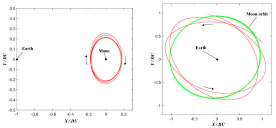
Figure 1.
DRO with a resonance ratio of 2:1 [22] (the track marked in red is DRO, the left figure shows the Earth–Moon rotating system, and the right figure shows the Earth-centered inertial system).
Laser ranging (LR) is a technique employed for accurate distance measurement between a laser ground station and an optical target (Corner Cube Reflector). Astronauts on Apollo 11, 14, and 15 deployed CCRs on the lunar surface in July 1969, February 1971, and July 1971, respectively [23]. Table 1 details the information about the deployed CCRs on the Moon. By emitting laser signals from the ground and measuring the echo signals from the CCRs, the distance between the Earth and the Moon can be determined, which is known as lunar laser ranging (LLR) technology. On 12 December 2023, NASA’s Lunar Reconnaissance Orbiter (LRO) directed a laser beam towards the Vikram lander located on the surface of the Moon. Subsequently, it received laser signals reflected back from the laser reflector array mounted on the lander. This achievement successfully demonstrated the ability to locate the reflector device on the lunar surface from lunar orbit, validating that spacecraft can accurately identify lunar objects using lunar laser ranging technology. In 2024, Chang’e-6 placed an Italian CCR on the far side of the Moon. This placement aimed to offer precise navigation services for lunar-orbiting satellites. It enabled these satellites to calculate distances accurately, assess their orbits, and enhance the precision of lunar landings.

Table 1.
Information on Corner Cube Reflectors deployed on the Moon [24].
To satisfy the requirements of stable and fast high-precision autonomous orbit determination schemes for cislunar space LLO spacecraft, this paper presents an autonomous orbit determination scheme for an LLO satellite using DRO-LLO SST and lunar laser ranging. Figure 2 illustrates the autonomous orbit determination scenario. One satellite in the formation orbits around the DRO, while the other satellite orbits around the LLO. Both satellites carry high-performance transceivers for inter-satellite measurements. For the microwave link, deploying microwave equipment on the lunar surface is required. However, the lunar surface environment is extremely harsh, characterized by drastic temperature variations, prolonged lunar nights, and other challenges, which render it highly difficult to deploy microwave equipment capable of long-term stable operation. In contrast, laser CCRs are passive devices with excellent adaptability to the lunar environment, and their engineering applicability has been validated in practical missions. Therefore, the LLO satellite is additionally equipped with laser ranging equipment for laser ranging with the lunar corner reflectors. The inter-satellite and lunar laser ranging data are combined with orbital dynamics, and the orbit determination of the DRO and LLO satellites can be achieved using the EKF algorithm.
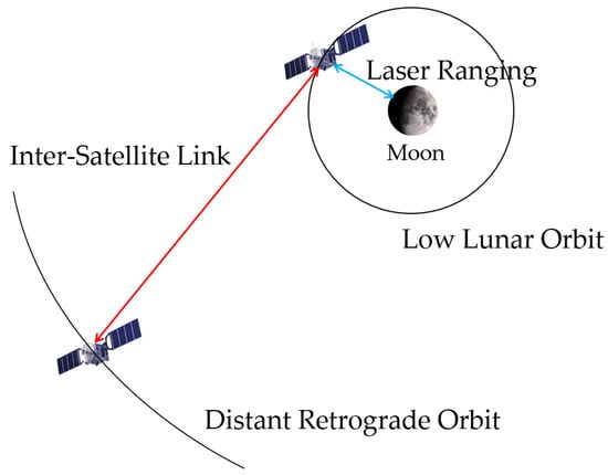
Figure 2.
Autonomous orbit determination scheme for the DRO-LLO satellite formation in the Earth–Moon rotating system.
2. Measurement Model
2.1. Inter-Satellite Ranging Model
The inter-satellite ranging model is a bidirectional one-way measurement model, in which spacecraft at both ends of the inter-satellite link send and receive measurement signals from each other. By measuring the difference in signal propagation time and frequency, the distance and clock information between two spacecraft can be obtained.
Taking a DRO satellite and an LLO satellite as examples, Figure 3 shows a schematic diagram of the bidirectional one-way ranging model. The bidirectional link measurement models for satellite D (DRO satellite) and satellite L (LLO satellite) can be represented as follows [7,17,25]:
where is the pseudo range received by the DRO satellite at time and transmitted by the LLO satellite at time ; is the pseudo range received by the LLO satellite at time and transmitted by the DRO satellite at time , and it is assumed that two satellites receive the ranging signal at the same time; and are the position vectors of the DRO satellite and the LLO satellite, respectively; is the speed of light; and are the device delay for the DRO satellite and the LLO satellite to receive the pseudo range, and are the device delay for the DRO satellite and the LLO satellite to send the pseudo range; and are the clock bias of the DRO satellite and the LLO satellite, respectively; and and are the measurement thermal noise of the DRO satellite and the LLO satellite receiving the pseudo range, and the measurement thermal noise is modeled as Gaussian white noise.
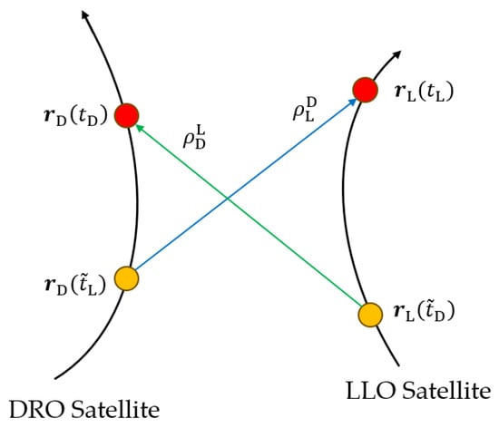
Figure 3.
Schematic diagram of dual one-way ranging system.
By summing and combining the bidirectional one-way measurement model, clock-related terms can be eliminated, achieving the decoupling of distance information and clock information.
where and are the geometric distances in the ranging signals received by the DRO satellite and the LLO satellite; is the sum of the receiving delay and sending delay of bidirectional link devices; is the clock bias variation value of the LLO satellite during the time period ; and is the clock bias variation value of the DRO satellite during the time period . The magnitude of the measurement system delay is related to the ambient temperature of the measurement payload. Under the condition of a slow temperature change, the system delay () can be modeled as a constant within a certain period of time. Considering that the clock bias changes in the DRO and LLO satellites in a short period of time are very small (measured atomic clock drift ranges from 10−10 s/s to 10−11 s/s), and can be ignored, and Equation (2) can be further expressed as follows:
In filtering, system delay and clock bias are treated as known parameters.
2.2. Lunar Laser Ranging Model
Lunar laser ranging is a relay-based measurement, which includes the uplink signal from the satellite to the lunar corner reflector and the downlink signal from the lunar corner reflector to the satellite. If the two-way distance measurement time is marked at the satellite reception time , then the lunar corner reflector receives and forwards signals at the time and the satellite transmission signal time is . represents the downlink light and represents the uplink light. Figure 4 shows a schematic diagram of the transponder ranging system.
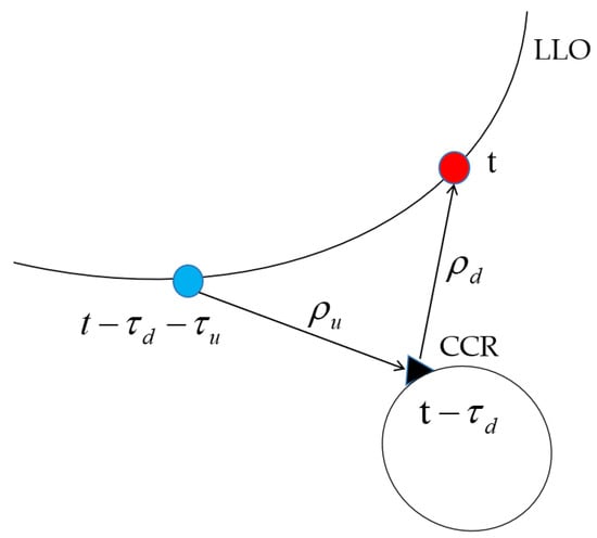
Figure 4.
Schematic diagram of transponder ranging system.
Ranging modeling requires the iterative solution of the downlink and uplink optical time equations. The downward light can be determined through fixed-point continuous iteration, with an initial value of . The calculation formula is as follows [26]:
where is the position vector of the satellite and is the position vector of the lunar corner reflector. Continuous iteration is conducted until the difference between two consecutive values is less than a specific threshold. In the simulation experiment, the specific threshold is taken as 10−12. Similarly, the calculation formula for uplink light is as follows:
The two-way distance measurement is modeled as the sum of the up distance and down distance, that is:
3. Autonomous Orbit Determination Algorithm
3.1. Orbital Dynamics Model
Assuming represents the position and velocity state of the satellite at time , the orbital dynamics equation is as follows [17]:
where and , respectively, represent the gravity acceleration of the Earth and the Moon; represents the sum of the gravity perturbation accelerations of the three bodies of the Sun, Mars, Jupiter, and Saturn; is the acceleration of solar radiation pressure; and is the process noise, modeled as Gaussian white noise.
The orbital state at the initial time is denoted as , and the state transition matrix from time to time is represented as:
The transition matrix from process noise to track state is , calculated as follows:
where is the time step and is the identity matrix.
3.2. Extended Kalman Filter Algorithm
Considering the nonlinear situation of practical engineering, this article chooses the Extended Kalman Filter (EKF) to process the measurement data of each epoch. Given the initial epoch state parameter and state covariance matrix of the satellite, the EKF is used to process the inter-satellite measurement data and lunar laser ranging data, achieving the optimal estimation of the estimated state parameters. The definition of the estimated state is as follows:
where is the solar radiation pressure coefficient. Among the non-conservative forces acting on the satellite, solar radiation pressure is the largest in magnitude. However, the physical mechanism of solar radiation pressure indicates that the radiation pressure models of different spacecrafts have their specificities, and the modeling work is relatively complex [27]. Therefore, the solar radiation pressure coefficient is taken as the estimated parameter.
The EKF process includes two steps: time update and measurement update.
Time update stage: this uses the state parameter and state covariance matrix of epoch to calculate the prior state parameter and prior state covariance matrix . The calculation formula is as follows [7,22,28]:
where is the covariance matrix of process noise, with diagonal elements representing process noise compensation values. The compensation values are set based on the magnitude of unmodeled dynamic errors, and adjusting can prevent the state covariance matrix from converging too quickly. In the simulation test, the magnitude of the diagonal elements in are determined by the trial-and-error method [20]. The principle relied on is that the posterior O-C residual conforms to the characteristics of Gaussian noise, and the standard deviation is close to the magnitude of the ranging thermal noise. The state transition matrix and the process noise transition matrix are represented as follows:
Measurement update stage: this uses the measurement data of the current epoch to calculate the state parameter and state covariance matrix , with the following calculation formula:
where is Kalman gain; is the covariance matrix of the measurement noise; is the prior measurement prediction value calculated using prior state parameters; is the observation data of the current epoch (inter-satellite ranging data and laser ranging data are obtained simultaneously); and is the design matrix of the state parameters estimated based on the observed data, and the calculation formula is as follows:
4. Autonomous Orbit Determination Simulation
4.1. Simulation Setting
The simulation uses the DRO (resonance ratio 2:1) at a distance of about 400,000 km from Earth and 70,000–100,000 km from the Moon, and the LLO at a distance of 300 km from the Moon’s surface. The initial states of the DRO and the LLO are shown in Table 2 and Table 3. The simulation lasts for 30 days, starting at 0:00 UTC on 1 January 2023 and ending at 0:00 UTC on 31 January 2023.
Table 2.
Initial states of the DRO (represented in the lunar center inertial coordinate system).
Table 3.
Initial states of the LLO (represented in the lunar center inertial coordinate system).
Each simulation experiment is divided into four control groups: the first group only uses the DRO-LLO inter-satellite link data for the LiAISON navigation simulation; the second, third, and fourth groups have LLO lunar laser ranging schemes added based on the DRO-LLO inter-satellite link, with two (A5, A6), six (A5, A6, A11, A12, A15, A16), and ten (A5, A6, A11–A18) lunar corner reflectors, respectively. During the orbit determination process, the satellite does not perform any maneuvers. When obtaining the observation data, the line-of-sight visibility between the satellites is taken into account, that is, whether they will be obscured by the Earth or the Moon.
The latitude and longitude of the lunar corner reflectors are shown in Table 4. In the experiment, the effective reflection angle of the corner reflector is set to 45 degrees. Only when the angle between the laser link and the corner reflector is not larger than this angle can the LLO satellite obtain laser ranging data. The measurement duration of the LLO satellite and lunar corner reflectors is shown in Figure 5. The average measurement interval between the LLO satellite and the two corner reflectors A5 and A6 is 132 min, and the average measurement time is 6 min. The measurement intervals between the LLO satellite and A11-A18 corner reflectors also follow a periodic distribution.
Table 4.
Latitude and longitude of the lunar corner reflectors in the lunar fixed coordinate.
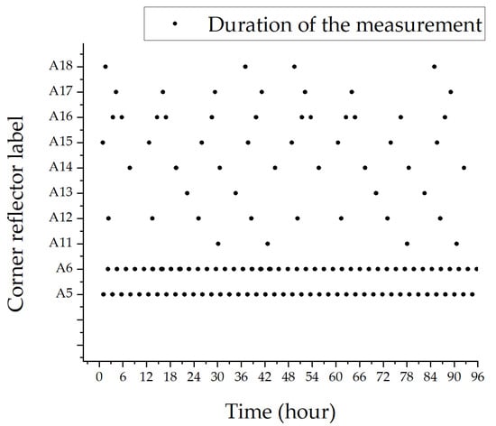
Figure 5.
Measurement duration of the LLO satellite and lunar corner reflectors.
The dynamic model and integrator parameter settings for generating the reference satellite orbit are shown in Table 5, and the specific simulation conditions are shown in Table 6.
Table 5.
Force model and integrator settings.
Table 6.
Simulation setting conditions.
4.2. Analysis of Cramér–Rao Lower Bound
In order to verify the observability of autonomous orbit determination, the Cramér–Rao Lower Bound (CRLB) analysis is conducted on the DRO-LLO autonomous orbit determination. The Cramér-Rao Lower Bound is a theoretical lower limit for measuring the accuracy of parameter estimation, which is the best estimation accuracy that unbiased estimators can achieve under optimal conditions [20]. So, for the real filtering results:
where is the error covariance matrix corresponding to the unbiased estimation of the parameter to be estimated, and is the lower limit of the CRLB.
For the initial epoch:
The calculation method of the CRLB covariance matrix for other epochs:
The main difference between the EKF and the CRLB is that the EKF uses the estimated orbit of the current epoch, while the CRLB uses the reference orbit and does not contain process noise [20].
In the DRO-LLO satellite formation scenario, an inter-satellite link is constructed between the DRO and the LLO, and a corner reflector is deployed on the lunar surface for the LLO satellite to perform lunar laser ranging. This simulation starts at 0:00 UTC on 1 January 2023 and ends at 0:00 UTC on 20 February 2023. The simulation experiments are divided into two groups. In one group, the laser ranging data are acquired throughout the whole period, while in the other group, the laser measurement is continuously carried out for 20 min every two hours. However, due to the obstruction of the Moon, the laser equipment in these two groups does not continuously carry out ranging to the lunar corner reflectors, but works intermittently. The standard deviation of the initial orbit error is set to 1000 m and 0.1 m/s, and Figure 6 shows the lower limit results of the CRLB for the DRO and LLO satellites.
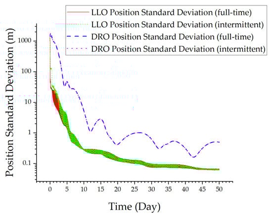
Figure 6.
Analysis of Cramér–Rao Lower Bound.
The CRLB results show that the following: ① Within 4 days, the DRO position converges to below 100 m and the LLO position converges to below 10 m. ② Within 30 days, the DRO position converges to 1 m and the LLO position converges to 0.1 m. ③ The CRLB results of full-time measurement and intermittent measurement differ very little. Based on the CRLB results, estimations of the orbital states of the DRO and the LLO using inter-satellite measurements and lunar laser ranging data are observable and have the potential to achieve a high level of accuracy. In practical engineering, the limitations of laser ranging will not have a significant impact on the orbit determination results. Additionally, the position standard deviation of the DRO and LLO satellites experiences minimal variation after 30 days. Consequently, 30 days is chosen as the orbit determination duration for the subsequent simulation.
4.3. Autonomous Orbit Determination Results
In the experimental data generation stage, reference orbits and measurement data are obtained. Then, the EKF is used for autonomous orbit determination and the estimated orbit is obtained. Finally, the estimated orbit is compared with the reference orbit to output position and velocity residuals.
This article conducts three sets of numerical simulation experiments: ① Experiment 1: tests the impact of lunar laser ranging data on the autonomous LiAISON orbit determination performance of the DRO-LLO; ② Experiment 2: tests the impact of increasing initial error on the autonomous orbit determination performance of the DRO-LLO; and ③ Experiment 3: tests the impact of different dynamic model errors on the autonomous orbit determination performance of the DRO-LLO.
The initial simulation settings for Experiment 1 are shown in Table 7.
Table 7.
Initial simulation settings for Experiment 1.
Figure 7 and Figure 8 present the autonomous orbit determination results of the DRO-LLO in Experiment 1.
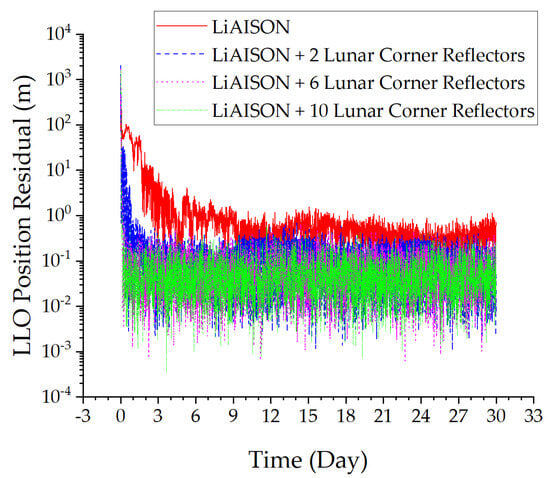
Figure 7.
LLO position residual.
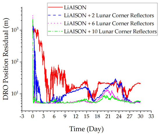
Figure 8.
DRO position residual.
From Figure 7 and Figure 8, the following can be concluded: ① Increasing lunar laser ranging data has improved the convergence speed of orbit determination for the LLO and DRO satellites. ② Increasing lunar laser ranging data has improved the orbit determination accuracy of the LLO and DRO satellites. The orbit determination accuracy of the LLO satellite has been improved from decimeters to centimeters, and the orbit determination accuracy of the DRO satellite has been improved from tens of meters to meters. ③ As the number of corner reflectors increases, the convergence speed and orbit determination accuracy of satellites continue to improve. In summary, lunar laser ranging technology has improved the convergence speed and accuracy of satellite orbit determination without considering dynamic model errors.
The initial simulation settings for Experiment 2 are shown in Table 8.
Table 8.
Initial simulation settings for Experiment 2.
Figure 9 and Figure 10 present the autonomous orbit determination results of the DRO-LLO in Experiment 2.
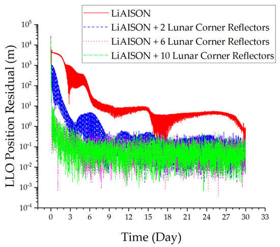
Figure 9.
LLO position residual.

Figure 10.
DRO position residual.
From Figure 9 and Figure 10, the following can be concluded: ① Increasing the initial orbit error significantly reduces the convergence speed of autonomous orbit determination relying solely on LiAISON. ② Increasing lunar laser ranging data has improved the orbital convergence speed and accuracy of the DRO and LLO satellites. The orbit determination accuracy of the LLO satellite has been improved from meters to decimeters, and the orbit determination accuracy of the DRO satellite has been improved from tens of meters to meters. ③ As the number of corner reflectors increases, the convergence speed and orbit determination accuracy of satellites continue to improve. In summary, lunar laser ranging technology can improve the robustness of satellite orbit determination, ensuring the convergence speed and accuracy without considering dynamic model errors and increasing initial orbit errors.
The initial simulation settings for Experiment 3 are shown in Table 9. The models of the non-spherical harmonic gravity fields of the Earth and the Moon have been matured, there is no need to analyze starting from the point-mass model [30,31]. Therefore, an order of 30 is selected to simulate the errors of the dynamic model.
Table 9.
Initial simulation settings for Experiment 3.
Figure 11 and Figure 12 present the autonomous orbit determination results of the DRO-LLO in Experiment 3.
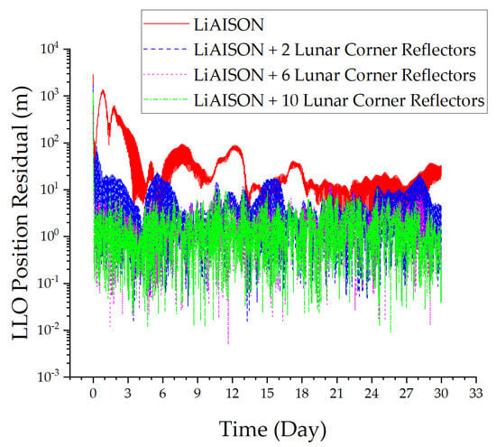
Figure 11.
LLO position residual.
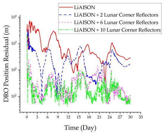
Figure 12.
DRO position residual.
From Figure 11 and Figure 12, the following can be concluded: ① Increasing the error of the dynamic model significantly reduces the convergence speed and accuracy of autonomous orbit determination relying solely on LiAISON; the orbit determination accuracy of the LLO satellite has decreased from decimeters to ten meters, and the orbit determination accuracy of the DRO satellite has decreased from tens of meters to hundreds of meters. ② Increasing lunar laser ranging data has improved the orbital convergence speed and accuracy of the DRO and LLO satellites. The orbit determination accuracy of the LLO satellite has been improved from tens of meters to meters, and the orbit determination accuracy of the DRO satellite has been improved from hundreds of meters to tens of meters. ③ As the number of corner reflectors increases, the convergence speed and orbit determination accuracy of satellites continue to improve. In summary, considering the errors in the dynamic model, lunar laser ranging technology can improve the robustness of satellite orbit determination, ensuring the convergence speed and accuracy.
4.4. Simulation Result Analysis
Table 10, Table 11 and Table 12 are the orbit determination statistic results of three simulation experiments. The position accuracy and velocity accuracy of the simulation experiments refer to the 3D Root Mean Square (RMS) values calculated from the relative position residual sequence and the relative velocity residual sequence within the previous 24 days (the latter 80%).
Table 10.
Orbit determination accuracy with lunar surface laser ranging data added.
Table 11.
Orbit determination accuracy under large initial errors.
Table 12.
Orbit determination accuracy under dynamic model errors.
The results of the simulation experiment indicate the following:
- ①
- In the autonomous orbit determination of the LLO spacecraft in cislunar space, relying solely on LiAISON for autonomous orbit determination will encounter issues like a long orbit convergence time and vulnerability to initial orbit errors and dynamic errors.
- ②
- Introducing lunar laser ranging technology can substantially enhance the convergence time and accuracy of the LLO satellite. Moreover, it improves the robustness of the navigation systems to initial orbit errors and dynamic model errors.
- ③
- The number of lunar corner reflectors also has a significant impact on navigation performance. When the number of lunar corner reflectors is relatively small, increasing the number of lunar corner reflectors can notably enhance the convergence time and accuracy of the orbit. However, when the number of lunar corner reflectors increases to six, further increasing it does not yield the same level of improvement.
5. Conclusions
This article presents a stable and high-precision autonomous orbit determination scheme for LLO spacecraft based on inter-satellite ranging and lunar laser ranging. This orbit determination scheme removes the dependence on ground measurement and control stations and mainly relies on lunar corner reflectors. The simulation results show that compared to autonomous orbit determination which depends exclusively on inter-satellite measurement, this scheme has a faster convergence speed, higher convergence accuracy, and better robustness of the navigation system to initial orbit errors and orbit dynamic model errors. Overall, it can provide valuable engineering references for the autonomous navigation of lunar-orbiting satellites.
Author Contributions
Conceptualization, S.C. and W.W.; Methodology, S.C., S.L. and J.P.; Software, S.C.; Validation, S.C.; Investigation, S.C. and Y.X.; Resources, W.W.; Data curation, S.C.; Writing—original draft, S.C.; Writing—review & editing, W.W. All authors have read and agreed to the published version of the manuscript.
Funding
This research received the funding support form the Strategic Priority Research Program of the Chinese Academy of Sciences, Grant No. XDA 300103000.
Data Availability Statement
The data that support the findings of this study are available from the corresponding author upon reasonable request.
Conflicts of Interest
The authors declare no conflict of interest.
References
- Gardner, T.; Cheetham, B.; Forsman, A.; Meek, C.; Kayser, E.; Parker, J.; Thompson, M.; Latchu, T.; Rogers, R.; Bryant, B.; et al. Capstone: A cubesat pathfinder for the lunar gateway ecosystem. In Proceedings of the Small Satellite Conference, Virtual Conference, 26–27 April 2021. [Google Scholar]
- Bridenstine, J. NASA’s Lunar Exploration Program Overview; NASA: Washington, DC, USA, 2020.
- Zhou, C.; Jia, Y.; Liu, J.; Li, H.; Fan, Y.; Zhang, Z.; Liu, Y.; Jiang, Y.; Zhou, B.; He, Z.; et al. Scientific objectives and payloads of the lunar sample return mission-Chang, e-5. Adv. Space Res. 2022, 69, 823–836. [Google Scholar] [CrossRef]
- Sundararajan, V. Overview and technical architecture of India’s Chandrayaan-2 mission to the Moon. In Proceedings of the AIAA Aerospace Sciences Meeting, Kissimmee, FL, USA, 8–12 January 2018. [Google Scholar]
- Choi, S.J.; Whitley, R.; Condon, G.; Loucks, M.; Park, J.I.; Choi, S.W.; Kwon, S.J. Trajectory design for the Korea Pathfinder Lunar Orbiter (KPLO). In Proceedings of the AAS/AIAA Astrodynamics Specialist Conference, Snowbird, UT, USA, 19–23 August 2018. [Google Scholar]
- Liu, S.; Yan, J.; Cao, J.; Ye, M.; Li, X.; Li, F.; Barriot, J. Review of the Precise Orbit Determination for Chinese Lunar Exploration Projects. Earth Space Sci. 2021, 8, 1361–2020. [Google Scholar] [CrossRef]
- Pu, J.H.; Li, S.L.; Liu, J.K.; Guo, P.; Wang, W. Space-based orbit determination and time synchronization of three typical lunar and Earth orbits. J. Deep. Space Explor. 2023, 10, 641–651. [Google Scholar]
- Ma, X.; Fang, J.C.; Ning, X.L.; Liu, G.; Ge, S.S. Autonomous celestial navigation for a deep space probe approaching a target planet based on ephemeris correction. Proc. Inst. Mech. Eng. Part G. J. Aerosp. Eng. 2015, 229, 2681–2699. [Google Scholar] [CrossRef]
- Hill, K.; Born, G.H. Autonomous interplanetary orbit determination using satellite-to-satellite tracking. J. Guid. Control Dyn. 2007, 30, 679–686. [Google Scholar] [CrossRef]
- Turan, E.; Speretta, S.; Gill, E. Autonomous navigation for deep space small satellites: Scientific and technological advances. Acta Astronaut. 2022, 193, 56–74. [Google Scholar] [CrossRef]
- Liu, J.; Wang, W.; Zhang, H.; Shu, L.; Gao, Y. Autonomous orbit determination and timekeeping in lunar distant retrograde orbits by observing X-ray pulsars. Navigation 2021, 68, 687–708. [Google Scholar] [CrossRef]
- Wang, W.; Shu, L.; Liu, J.; Gao, Y. Joint navigation performance of distant retrograde orbits and cislunar orbits via LiAISON considering dynamic and clock model errors. Navigation 2019, 66, 781–802. [Google Scholar] [CrossRef]
- Hesar, S.G.; Parker, J.S.; Leonard, J.M.; McGranaghan, R.M.; Born, G.H. Lunar far side surface navigation using Linked Autonomous Interplanetary Satellite Orbit Navigation (LiAISON). Acta Astronaut. 2015, 117, 116–129. [Google Scholar] [CrossRef]
- Cappelletti, C.; Battistini, S.; Malphrus, B. CubeSat Handbook: From Mission Design to Operations; Academic Press: Cambridge, MA, USA, 2020. [Google Scholar]
- Hill, K.A. Autonomous Navigation in Libration Point Orbits. Ph.D. Thesis, University of Colorado at Boulder, Boulder, CO, USA, 2007. [Google Scholar]
- Leonard, J.M. Supporting Crewed Missions Using LiAISON Navigation in the Earth-Moon System. Ph.D. Thesis, University of Colorado at Boulder, Boulder, CO, USA, 2015. [Google Scholar]
- Wang, W.B. Research on Autonomous Navigation and Timing of Earth Moon Spacecraft Based on DRO-LEO Formation. Ph.D. Thesis, Center for Space Application Engineering and Technology, Chinese Academy of Sciences, Beijing, China, 2020. [Google Scholar]
- Grenfell, P. Systems Performance Analysis for Autonomous Spacecraft Navigation within Satellite Constellations using Intersatellite Optical Communications Links. Ph.D. Thesis, Massachusetts Institute of Technology, Cambridge, MA, USA, 2024. [Google Scholar]
- Turan, E. Autonomous Navigation for Satellite Formations: Advancing Missions Beyond Earth with Inter-Satellite Radio Tracking. Ph.D. Thesis, Delft University of Technology, Delft, The Netherlands, 2024. [Google Scholar]
- Li, S.L.; Pu, J.H.; Guo, P.B.; Wang, W.; Zhang, W. Single-Beam Differential Relative Navigation of DRO Satellite Formation. J. Deep. Space Explor. 2023, 10, 211–219. [Google Scholar]
- Yang, C.H.; Fu, H.L.; Zhang, H. Close range natural and controlled formations on long-distance retrograde orbits. Acta Aeronaut. Sin. 2023, 44, 229–241. [Google Scholar]
- Pu, J.H.; Wang, W.B. Study on Autonomous Orbit Determination of Two Types of Long Period Orbits in the Cislunar Space. In Proceedings of the Chinese Congress of Theoretical and Applied Mechanics, Chengdu, China, 31 April–2 May 2022. [Google Scholar]
- Rao, R.Z. Key Physical and Technical Issues in Lunar Laser Ranging. Acta Opt. Sin. 2021, 41, 179–190. [Google Scholar]
- Turyshev, S.G.; Williams, J.G.; Folkner, W.M.; Gutt, G.M.; Baran, R.T.; Hein, R.C.; Somawardhana, R.P.; Lipa, J.A.; Wang, S. Corner-cube retro-reflector instrument for advanced lunar laser ranging. Exp. Astron. 2012, 36, 105–135. [Google Scholar] [CrossRef]
- Huang, Y.; Yang, P.; Chen, Y.L.; Li, P.J.; Zhou, S.S.; Tang, C.P.; Hu, X.G. Orbit determination of a cislunar space probe using Inter-Satellite Link data. Chin. Sci. Phys. Mech. Astron. 2023, 53, 132–144. (In Chinese) [Google Scholar]
- Montenbruck, O.; Gill, E. Satellite Orbits: Models, Methods, and Applications; Springer Science & Business Media: Berlin/Heidelberg, Germany, 2000. [Google Scholar]
- Shi, C.; Xiao, Y.; Fan, L.; Zheng, F.; Wang, C.; Huang, Z.; Li, Z. Research progress of radiation pressure modelling for navigation satellites. Acta Aeronaut. Astronaut. Sin. 2022, 43, 389–402. [Google Scholar]
- Liu, J.K. Simulation Study on Autonomous Navigation Technology of Earth Moon Space DRO Spacecraft Based on Pulsar GNSS and LEO Interstellar Links. M.S. Thesis, University of the Chinese Academy of Sciences, Beijing, China, 2022. [Google Scholar]
- Battat, J.B.R.; Adelberger, E.; Colmenares, N.R.; Farrah, M.; Gonzales, D.P.; Hoyle, C.D.; McMillan, R.J.; Murphy, T.W.; Sabhlok, S.; Stubbs, C.W. Fifteen Years of Millimeter Accuracy Lunar Laser Ranging with APOLLO: Data Set Characterization. Publ. Astron. Soc. Pac. 2023, 135, 104504. [Google Scholar] [CrossRef]
- Zheng, W.; Xu, H.Z.; Zhong, M.; Yuan, M.J.; Peng, B.B.; Zhou, X.H. Research progress and current situation of the Earth’s gravity field model. J. Geod. Geodyn. 2010, 30, 83–91. [Google Scholar]
- Yang, M.; Zhang, B.Y.; Yan, X.Y.; Li, Y.; Zhang, W.M.; Zhong, M.; Feng, W. Research progress on fine lunar gravity field modeling based on digital elevation model. Rev. Geophys. Planet. Phys. 2024, 55, 513–523. [Google Scholar]
Disclaimer/Publisher’s Note: The statements, opinions and data contained in all publications are solely those of the individual author(s) and contributor(s) and not of MDPI and/or the editor(s). MDPI and/or the editor(s) disclaim responsibility for any injury to people or property resulting from any ideas, methods, instructions or products referred to in the content. |
© 2025 by the authors. Licensee MDPI, Basel, Switzerland. This article is an open access article distributed under the terms and conditions of the Creative Commons Attribution (CC BY) license (https://creativecommons.org/licenses/by/4.0/).