
Aerodynamics Caused by Rolling Rates of a Small-Scale Supersonic Flight Experiment Vehicle with a Cranked-Arrow Main Wing

 ,
,
Abstract
1. Introduction
2. The Baseline Configuration M2011
3. The Conventional Theory
4. Wind-Tunnel Tests and CFD Analysis
4.1. Experimental Apparatus and Methods
4.2. Data Analysis Methods
4.3. CFD Analysis
5. Results and Discussions
6. Conclusions
Author Contributions
Funding
Data Availability Statement
Conflicts of Interest
Nomenclature and Abbreviation
| lift curve slope | |
| wingspan length | |
| drag coefficient | |
| lift coefficient | |
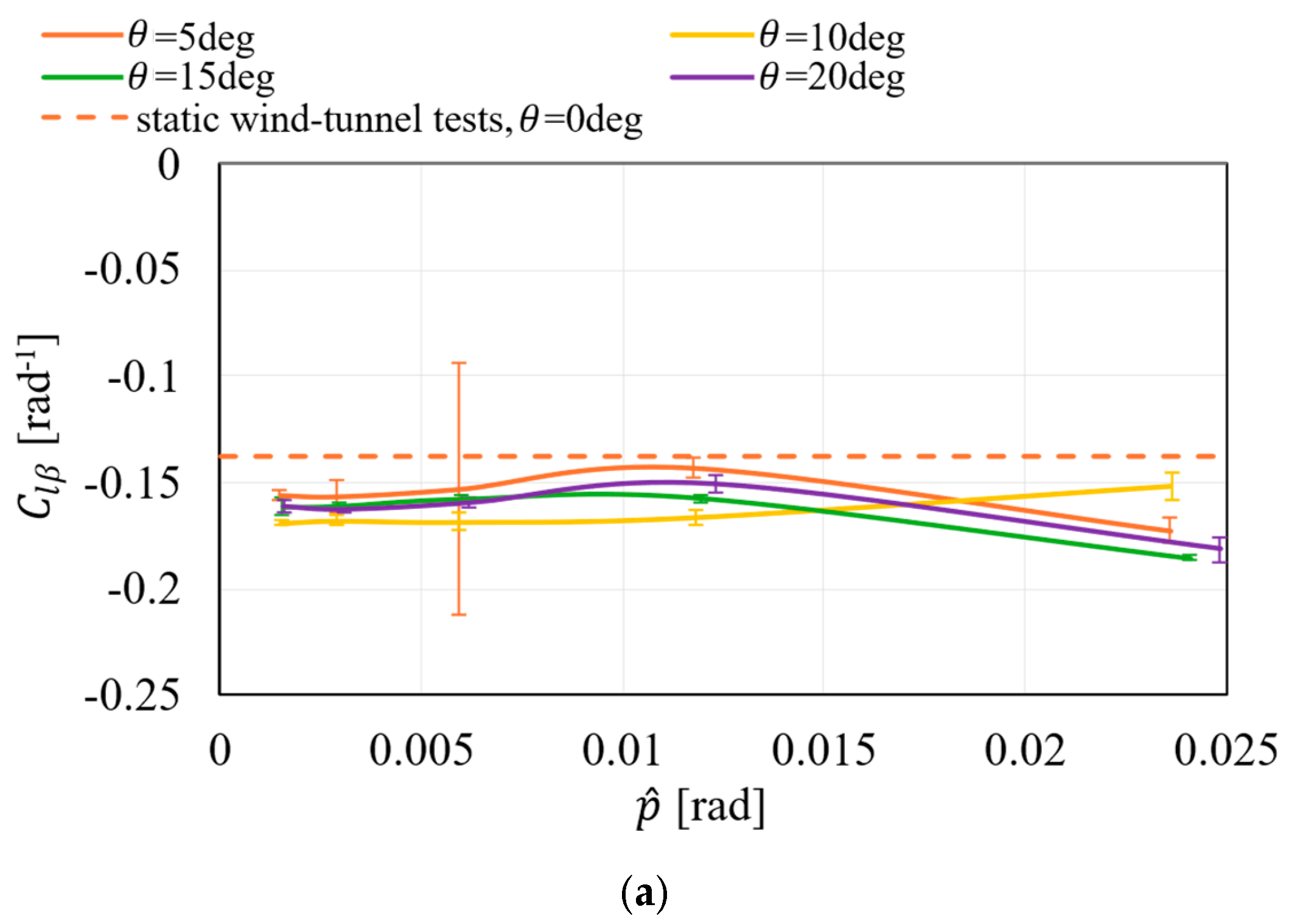
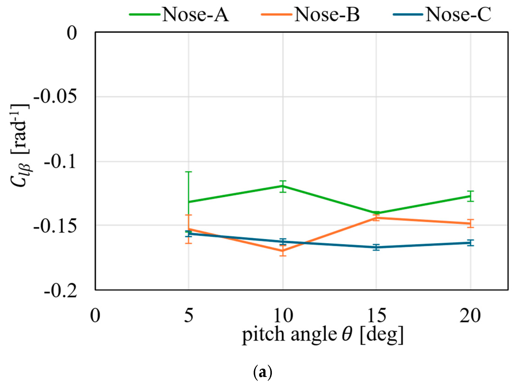
| rolling moment coefficient | |
| yawing moment coefficient | |
| chord length of the main wing at the lateral location | |
| drag force | |
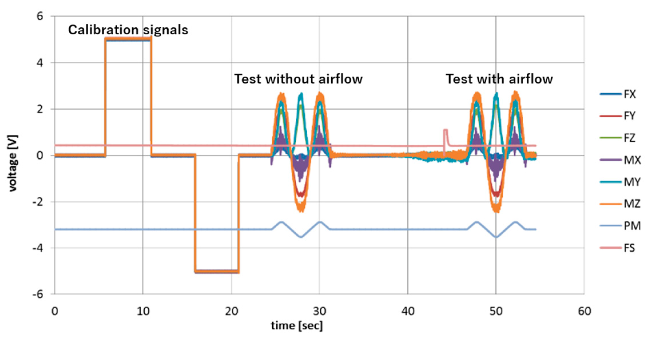
| FS | output signal of the anemometer |
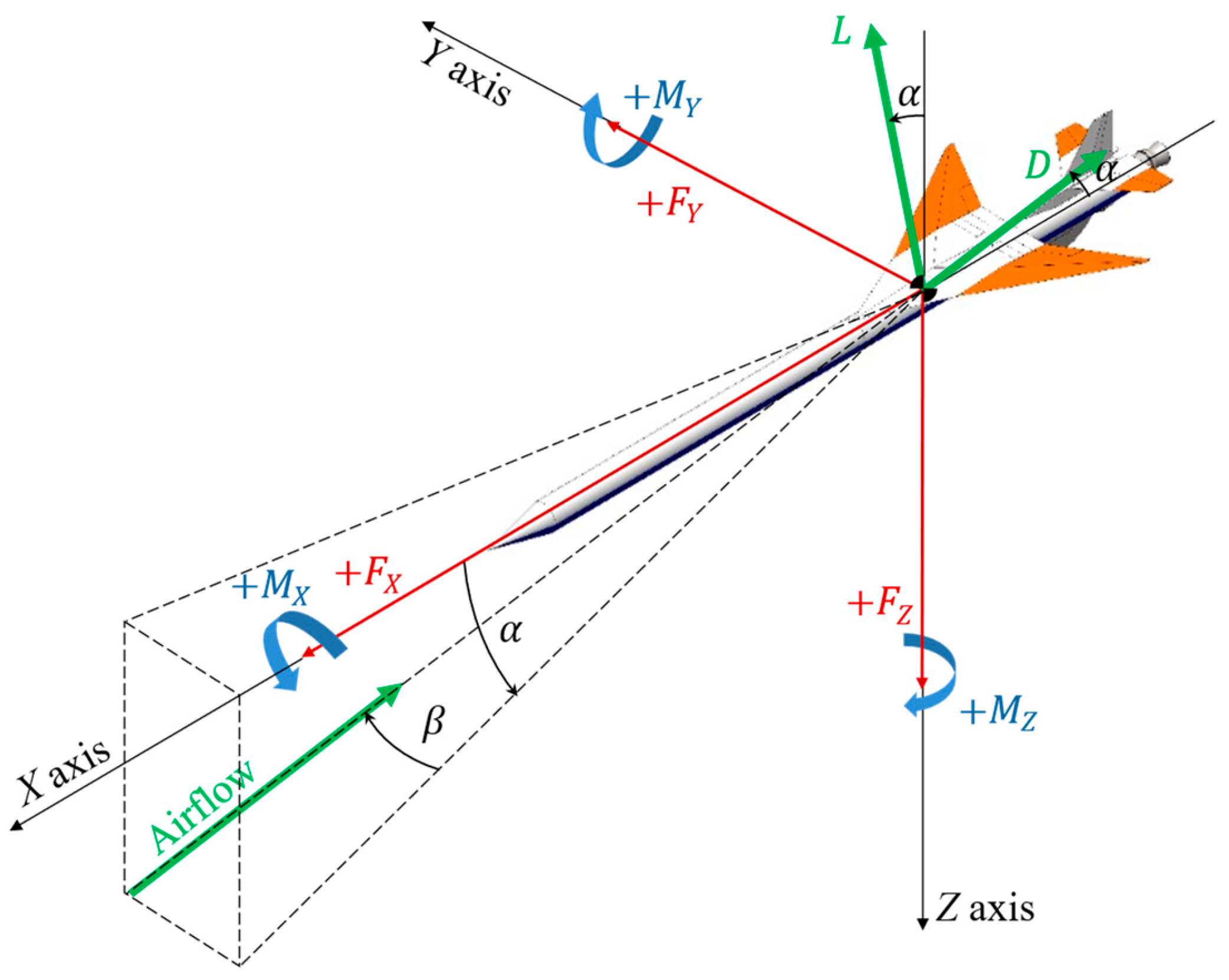
| , , | aerodynamic force components in the body-fixed coordinates |
| FX, FY, FZ | output signals from the internal balance for force components |
| lift force | |
| , , | aerodynamic moment components in the body-fixed coordinates |
| MX, MY, MZ | output signals from the internal balance for moment components |
| dimensional rolling rate | |
| non-dimensional rolling rate | |
| PM | output signal of the potentiometer |
| main-wing area | |
| freestream airspeed | |
| , , | body-fixed coordinates |
| lateral coordinate measured from body axis | |
| angle of attack | |
| sideslip angle | |
| zero-point shift in measured data | |
| pitch angle | |
| roll angle | |
| Subscripts | |
| derivative with respect to the sideslip angle | |
| derivative with respect to the aileron deflection angle | |
| derivative with respect to the nondimensional rolling rate |
References
- Minato, R.; Higashino, K.; Tanatsugu, N. Design and Performance Analysis of Bio-Ethanol Fueled GG-cycle Air Turbo Ramjet Engine. In Proceedings of the 50th AIAA Aerospace Science Meeting, Nashville, TN, USA, 9–12 January 2012. [Google Scholar]
- Mizobata, K.; Minato, R.; Higuchi, K.; Ueba, M.; Takagi, S.; Nakata, D.; Katsumata, N.; Higashino, K.; Tanatsugu, N. Development of a Small-scale Supersonic Flight Experiment Vehicle as a Flying Test Bed. In Proceedings of the 29th Congress of the International Council of the Aeronautical Sciences (ICAS), St. Petersburg, Russia, 7–12 September 2014. [Google Scholar]
- Perkins, C.D.; Hage, R.E. Airplane Performance Stability and Control; Wiley: Hoboken, NJ, USA, 1949. [Google Scholar]
- Weissman, R. Status of Design Criteria for Predicting Departure Characteristics and Spin Susceptibility. J. Airc. 1975, 12, 989–995. [Google Scholar] [CrossRef]
- Lan, C.E.; Hsu, C.H. Effects of Vortex Breakdown on Longitudinal and Lateral-Directional Aerodynamics of Slender Wings by the Suction Analogy. In Proceedings of the AIAA 9th Atmospheric Flight Mechanics Conference, San Diego, CA, USA, 9–11 August 1982. [Google Scholar]
- Freeman, D.C., Jr. Space Shuttle Orbiter Static Stability and Control Derivatives Obtained from Wind-Tunnel and Flight Tests. J. Spacec. 1982, 19, 12–14. [Google Scholar] [CrossRef]
- Croom, M.A.; Fratello, D.J.; Whipple, R.D.; O’Rourke, M.J.; Trilling, T.W. Dynamic Model Testing of the X-31 Configuration For High-Angle-of-Attack Flight Dynamics Research. AIAA-93-3674-CP. In Proceedings of the AIAA Flight Simulation and Technologies Conference, Monterey, CA, USA, 9–11 August 1993. [Google Scholar] [CrossRef]
- Owens, D.B.; Brandon, J.M.; Croom, M.A.; Fremaux, C.M.; Heim, E.H.; Vicroy, D.D. Overview of Dynamic Test Techniques for Flight Dynamics Research at NASA LaRC. In Proceedings of the 25th AIAA Aerodynamic Measurement Technology and Ground Testing Conference, San Francisco, CA, USA, 5–8 June 2006. [Google Scholar]
- Vicroy, D.D.; Loeser, T.D.; Schütte, A. SACCON Forced Oscillation Tests at DNW-NWB and NASA Langley 14x22-foot Tunnel. In Proceedings of the 28th AIAA Applied Aerodynamics Conference, Chicago, IL, USA, 28 June–1 July 2010. [Google Scholar]
- Murphy, P.C.; Klein, V.; Frink, N.T. Nonlinear Unsteady Aerodynamic Modeling Using Wind-Tunnel and Computational Data. J. Airc. 2017, 54, 659–683. [Google Scholar] [CrossRef]
- Bottigliero, R.; Rossano, V.; De Stefano, G. Transonic Dynamic Stability Derivative Estimation Using Computational Fluid Dynamics: Insights from a Common Research Model. Aerospace 2025, 12, 304. [Google Scholar] [CrossRef]
- Bunescu, I.; Hothazie, M.-V.; Stoican, M.-G.; Pricop, M.-V.; Onel, A.-I.; Afilipoae, T.-P. Numerical Study of the Basic Finner Model in Rolling Motion. Aerospace 2025, 12, 371. [Google Scholar] [CrossRef]
- Kwak, D.; Noguchi, M.; Shirotake, M.; Rinoie, K. Rolling Moment Characteristics of Supersonic Transport Configuration at High-Incidence Angles. J. Airc. 2006, 43, 1112–1119. [Google Scholar] [CrossRef]
- Kwak, D.; Hirai, K.; Rinoie, K.; Kato, H. Rolling Moment Characteristics at High Alpha on Several Planforms of Cranked Arrow Wing Configuration. In Proceedings of the 27th AIAA Applied Aerodynamics Conference, San Antonio, TX, USA, 22–24 June 2009. [Google Scholar]
- Kawazoe, H.; Yorikane, T.; Tone, Y. A Study on Dynamic Characteristics of Delta Wing in Rolling Motion Near Ground. In Proceedings of the 39th AIAA Aerospace Sciences Meeting, Reno, NV, USA, 8–11 January 2001. [Google Scholar]
- Yechout, T.R.; Morris, S.L.; Bossert, D.E.; Hallgren, W.F. Introduction to Aircraft Flight Mechanics; American Institute of Aeronautics and Astronautics: Reston, VA, USA, 2003. [Google Scholar]
- Etkin, B.; Reid, L.D. Dynamics of Flight, Stability and Control, 3rd ed.; Wiley: Hoboken, NJ, USA, 1996. [Google Scholar]
- Pope, A. High-speed Wind Tunnel Testing; R. E. Krieger Pub. Co.: Huntington, NY, USA, 1978. [Google Scholar]
- Shimizu, K.; Takahashi, S.; Miyakoshi, T.; Mizobata, K. Ground Effects in Aerodynamics of a Small-scale Supersonic Flight Experiment Vehicle with a Cranked-Arrow Main Wing. J. Evol. Space Act. 2024, 2, 193. [Google Scholar] [CrossRef]
- Haraguchi, S.; Sasaki, S.; Honda, A.; Nishida, A.; Kawanabe, R.; Mizobata, K. Flowfield Visualization and Mechanism of Dynamic Derivatives of a Small-scale Supersonic Flight Experiment Vehicle Being Developed at Muroran Institute of Technology. J. Evol. Space Act. 2023, 1, 60. [Google Scholar] [CrossRef]


| Dimension | Value |
|---|---|
| Wingspan | 2.41 m |
| Wing Area | 2.15 m2 |
| Fuselage Diameter | 0.3 m |
| Overall Length | Nose-A: 5.8 m (Propellants 80 kg) |
| Nose-B: 6.8 m (Propellants 105 kg) | |
| Nose-C: 7.8 m (Propellants 130 kg) |
| Derivative | Evaluated Value |
|---|---|
| −0.245 | |
| 0.0117 |
| Category | Item | Setting | |
|---|---|---|---|
| Vehicle model | 7/60-scale wind-tunnel test model, wingspan 0.282 m | ||
| Mesh generation | type | unstructured tetrahedral | |
| spacing | body surface: 1 mm inner and outer half circle: 60 points | ||
| number of cells | about four million | ||
| CFD analysis | Boundary Condition | body surface | Wall |
| inner spherical surface | Interface, 1 m radius | ||
| outer spherical surface | Pressure-far-field, 2 m radius | ||
| Governing equation | three-dimensional Navier–Stokes | ||
| Spatial Discretization | second-order upwind differencing | ||
| Fluid | air/ideal gas | ||
| Viscosity model | Sutherland | ||
| Turbulence model | Spalart–Allmaras | ||
| Mach number | 0.6 | ||
| Derivative | -Averaged | = 0 deg. | [2], = 0 deg. | [10], = 2.5 deg. | [10], = 2 deg. |
|---|---|---|---|---|---|
| −0.156 | −0.0970 | −0.106 | −0.0951 | −0.0930 | |
| 0.117 | 0.126 | 0.146 | 0.210 | 0.242 |
Disclaimer/Publisher’s Note: The statements, opinions and data contained in all publications are solely those of the individual author(s) and contributor(s) and not of MDPI and/or the editor(s). MDPI and/or the editor(s) disclaim responsibility for any injury to people or property resulting from any ideas, methods, instructions or products referred to in the content. |
© 2025 by the authors. Licensee MDPI, Basel, Switzerland. This article is an open access article distributed under the terms and conditions of the Creative Commons Attribution (CC BY) license (https://creativecommons.org/licenses/by/4.0/).
Share and Cite
Mizobata, K.; Shirakata, K.; Honda, A.; Shiono, K.; Ishigami, Y.; Nishida, A.; Miura, M. Aerodynamics Caused by Rolling Rates of a Small-Scale Supersonic Flight Experiment Vehicle with a Cranked-Arrow Main Wing. Aerospace 2025, 12, 572. https://doi.org/10.3390/aerospace12070572
Mizobata K, Shirakata K, Honda A, Shiono K, Ishigami Y, Nishida A, Miura M. Aerodynamics Caused by Rolling Rates of a Small-Scale Supersonic Flight Experiment Vehicle with a Cranked-Arrow Main Wing. Aerospace. 2025; 12(7):572. https://doi.org/10.3390/aerospace12070572
Chicago/Turabian StyleMizobata, Kazuhide, Koji Shirakata, Atsuya Honda, Keisuke Shiono, Yukiya Ishigami, Akihiro Nishida, and Masaaki Miura. 2025. "Aerodynamics Caused by Rolling Rates of a Small-Scale Supersonic Flight Experiment Vehicle with a Cranked-Arrow Main Wing" Aerospace 12, no. 7: 572. https://doi.org/10.3390/aerospace12070572
APA StyleMizobata, K., Shirakata, K., Honda, A., Shiono, K., Ishigami, Y., Nishida, A., & Miura, M. (2025). Aerodynamics Caused by Rolling Rates of a Small-Scale Supersonic Flight Experiment Vehicle with a Cranked-Arrow Main Wing. Aerospace, 12(7), 572. https://doi.org/10.3390/aerospace12070572