
Reconstruction and Separation Method of Ranging and Communication Phase in Beat-Note for Micro-Radian Phasemeter


Abstract
1. Introduction
2. Modulation Phase Impact
3. Modulation Component Reconstruction and Separation
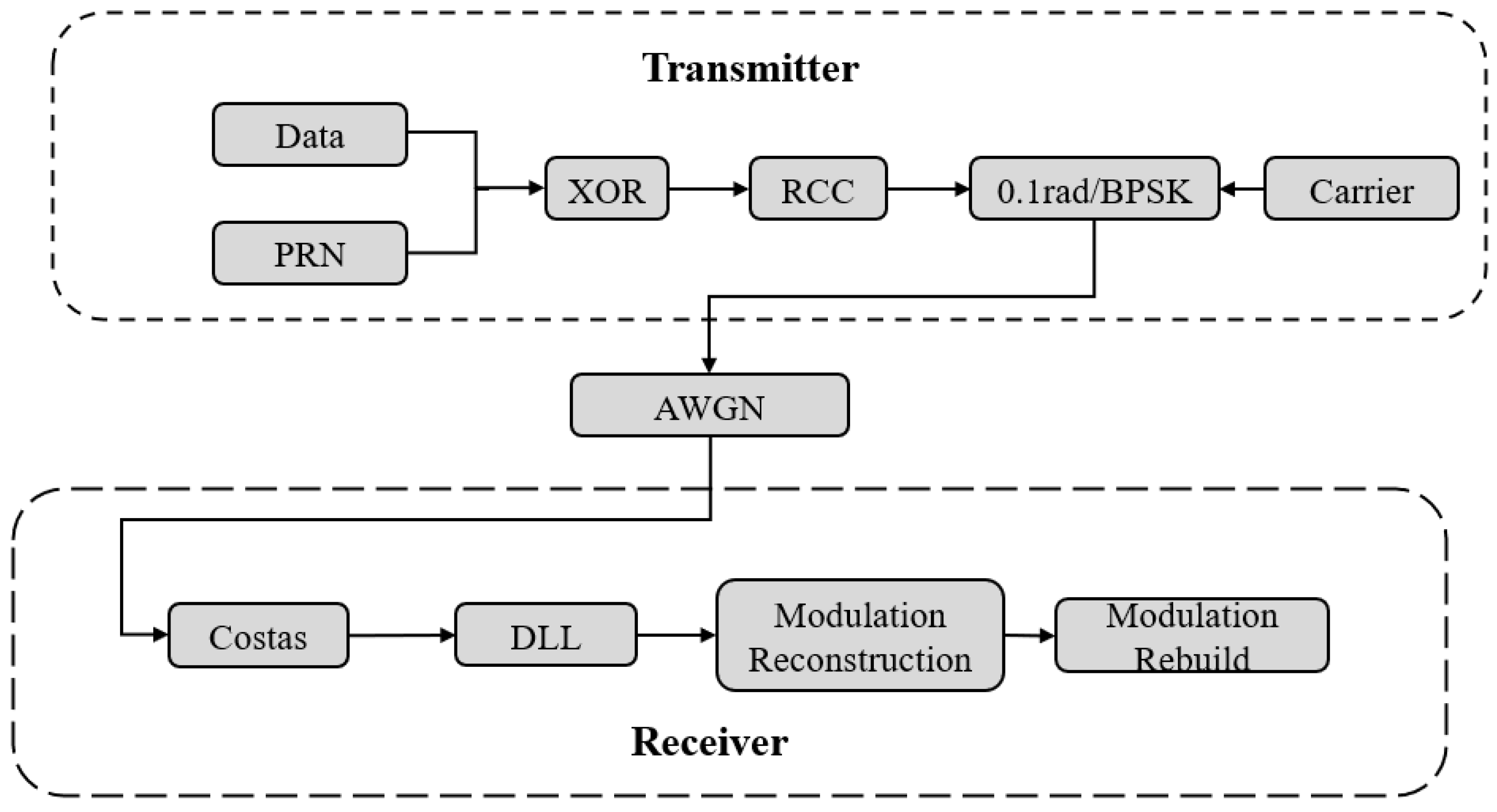
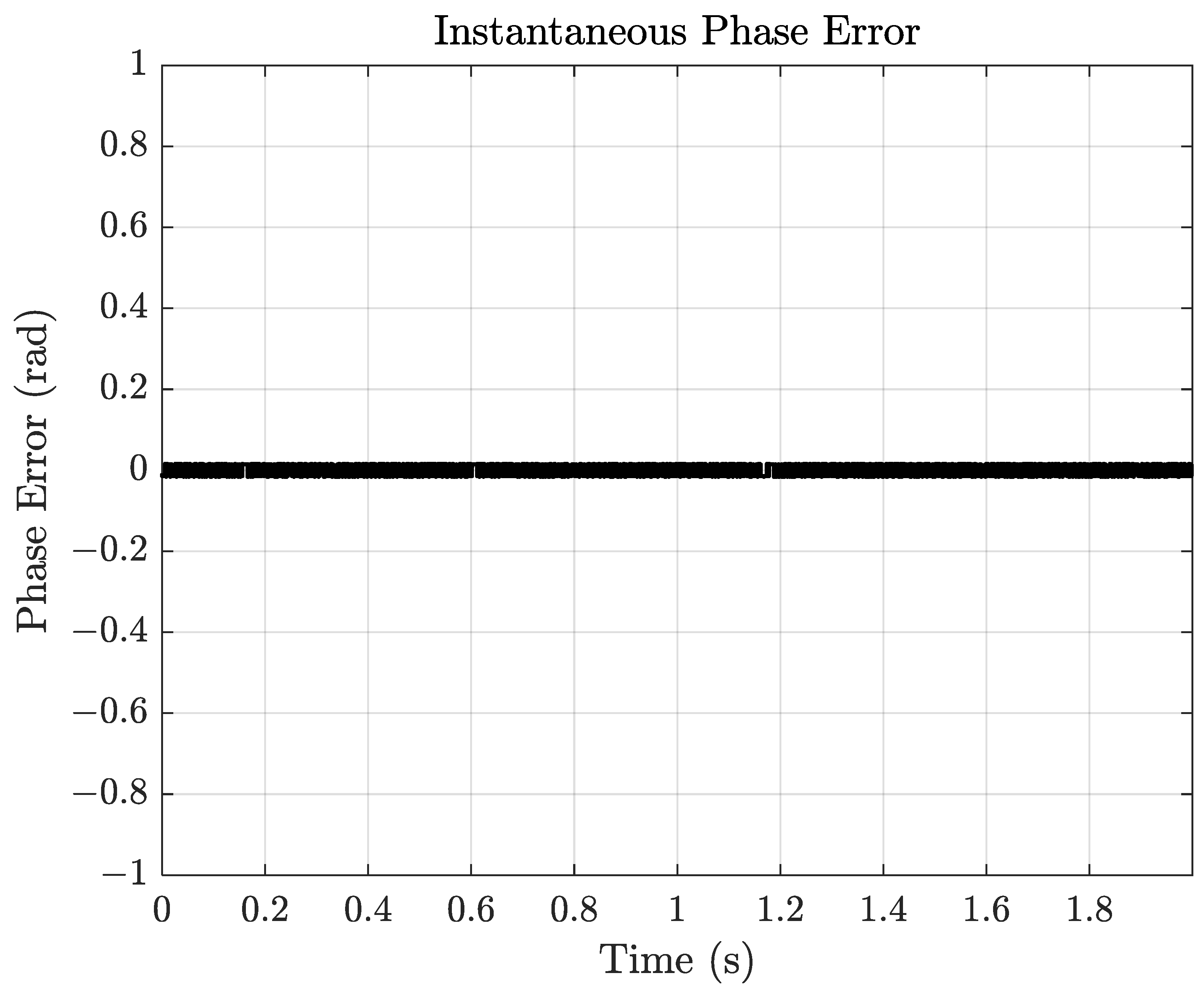
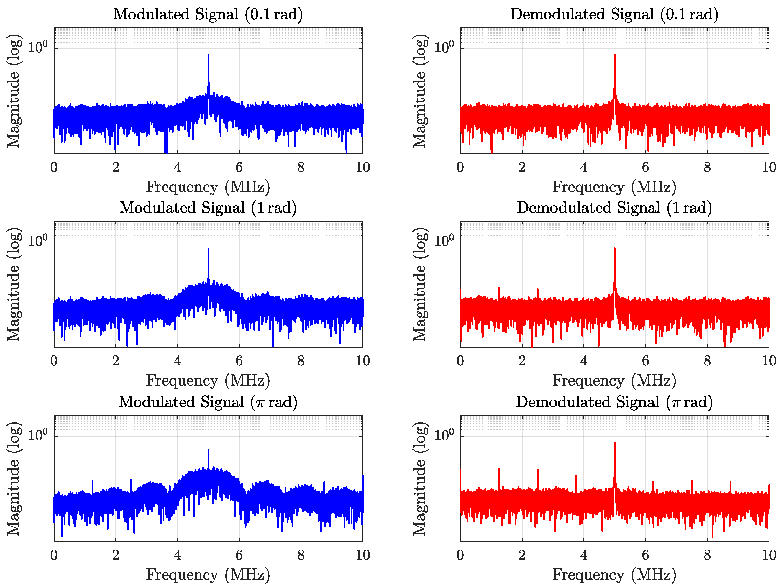
4. Simulation Experiment Verification
5. Conclusions and Outlook
Author Contributions
Funding
Data Availability Statement
Conflicts of Interest
References
- Heinzel, G. Ranging with pseudo-random noise. In Proceedings of the LISA International Science Team (LIST) Meeting, Philadelphia, PA, USA, 3–8 November 2002; p. 17. [Google Scholar]
- Pollack, S.E.; Stebbins, R.T. A demonstration of LISA laser communication. Class. Quantum Gravity 2006, 23, 4201. [Google Scholar] [CrossRef]
- Heinzel, G.; Esteban, J.J.; Barke, S.; Otto, M.; Wang, Y.; Garcia, A.F.; Danzmann, K. Auxiliary functions of the LISA laser link: Ranging, clock noise transfer and data communication. Class. Quantum Gravity 2011, 28, 094008. [Google Scholar] [CrossRef]
- Esteban, J.J.; García, A.F.; Barke, S.; Peinado, A.M.; Cervantes, F.G.; Bykov, I.; Heinzel, G.; Danzmann, K. Experimental demonstration of weak-light laser ranging and data communication for LISA. Opt. Express 2011, 19, 15937–15946. [Google Scholar] [CrossRef] [PubMed]
- Delgado, J.J.E.; Marin, A.F.G.; Bykov, I.; Heinzel, G.; Danzmann, K. Free-space laser ranging and data communication. In Proceedings of the 2009 6th Workshop on Positioning, Navigation and Communication, Hannover, Germany, 19 March 2009; IEEE: Piscataway, NJ, USA, 2009; pp. 275–281. [Google Scholar]
- Liu, H.S.; Gao, R.H.; Luo, Z.R.; Jin, G. Laser ranging and data communication for space gravitational wave detection. Chin. Opt. 2019, 12, 486–492. [Google Scholar]
- Han, S.; Tong, J.; Wang, Z.; Yu, T.; Sui, Y. Simulation system of a laser heterodyne interference signal for space gravitational wave detection. Infrared Laser Eng. 2022, 51, 20210572. [Google Scholar]
- Deng, R.J.; Zhang, Y.B.; Liu, H.S.; Luo, Z.R. Ground electronics verification of inter-satellites laser ranging in the Taiji program. Chin. Opt. 2023, 16, 765–776. [Google Scholar]
- Zhang, Y.B.; Deng, R.J.; Liu, H.S.; Luo, Z.R. Parameter design and experimental verification of taiji program inter-satellite laser communication. Chin. J. Lasers 2023, 50, 2306002. [Google Scholar]
- Yamamoto, K. Intersatellite Clock Synchronization and Absolute Ranging for Gravitational Wave Detection in Space; Leibniz Universität Hannover: Hannover, Germany, 2023. [Google Scholar]
- Long, H.Y.; Yu, T.; Xue, K.; Wang, Z. Design of Ranging Communication Coding and Noise Suppression Methods in Space Gravitational Wave Detection. Symmetry 2025, 17, 40. [Google Scholar] [CrossRef]
- Reinhardt, J.N.; Staab, M.; Yamamoto, K.; Bayle, J.B.; Hees, A.; Hartwig, O.; Wiesner, K.; Shah, S.; Heinzel, G. Ranging sensor fusion in LISA data processing: Treatment of ambiguities, noise, and onboard delays in LISA ranging observables. Phys. Rev. D 2024, 109, 022004. [Google Scholar] [CrossRef]
- Sweeney, D. Laser Communications for LISA and the University of Florida LISA Interferometry Simulator. Ph.D Thesis, University of Florida, Gainesville, FL, USA, 2012. [Google Scholar]
- Jiang, Q.; Dong, P.; Liu, H.S.; Luo, Z.R. Ground-based principle verification of clock noise transfer for the Taiji program. Chin. Opt. 2023, 16, 1394–1403. [Google Scholar]
- Gao, X.; Yi, Z.; Lian, J.; Long, W.; Li, Z. Communication reliability analysis of inter-satellite laser link based on transmission parameters. In Proceedings of the 4th Optics Young Scientist Summit (OYSS 2020), Ningbo, China, 4–7 December 2020; SPIE: Bellingham, WA, USA, 2021; Volume 11781, pp. 485–494. [Google Scholar]
- Liu, H.S.; Luo, Z.R.; Gang, J. The development of phasemeter for Taiji space gravitational wave detection. Microgravity Sci. Technol. 2018, 30, 775–781. [Google Scholar] [CrossRef]
- Shachi, P.; Mishra, R.; Jatoth, R.K. Coherent BPSK demodulator using Costas loop and early-late gate synchronizer. In Proceedings of the 2013 Fourth International Conference on Computing, Communications and Networking Technologies (ICCCNT), Tiruchengode, India, 4–6 July 2013; IEEE: Piscataway, NJ, USA, 2013; pp. 1–6. [Google Scholar]
- Bhatti, B.A.; Umer, M.; Ahmed, W.; Tariq, M.H.; Ali, U. Carrier and symbol synchronization in digital receivers using feedback compensation loop and early late gate on FPGA. In Proceedings of the 2014 International Conference on Robotics and Emerging Allied Technologies in Engineering (iCREATE), Islamabad, Pakistan, 22–24 April 2014; IEEE: Piscataway, NJ, USA, 2014; pp. 146–150. [Google Scholar]
- Han, S. Design and Implementation of Phasemeter Test System for Space Gravitational Wave Detection. Master’s Thesis, University of Chinese Academy of Sciences (Changchun Institute of Optics, Fine Mechanics and Physics, Chinese Academy of Sciences), Changchun, China, 2022. [Google Scholar]


| Type | Value | Remarks |
|---|---|---|
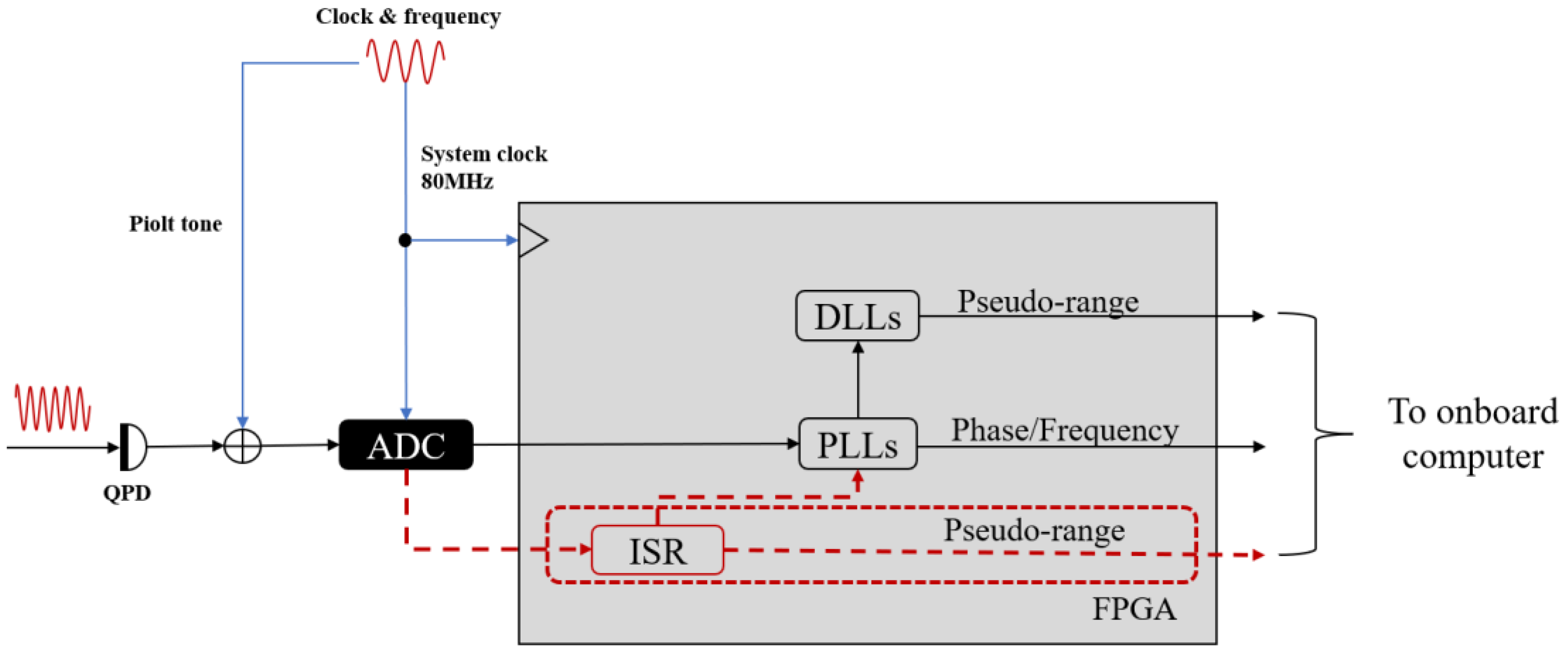
| System frequency | 80 MHz | Gravitational wave design |
| PRN code rate | 1.6 MHz | According to reference [11] |
| Samples per chip | 50 | |
| fpreading factor | 64 | |
| data rate | 25 KHz | |
| PRN sequence length | 1024 | |
| Carrier frequency | 5 MHz | 5~25 MHz interference measurement band |
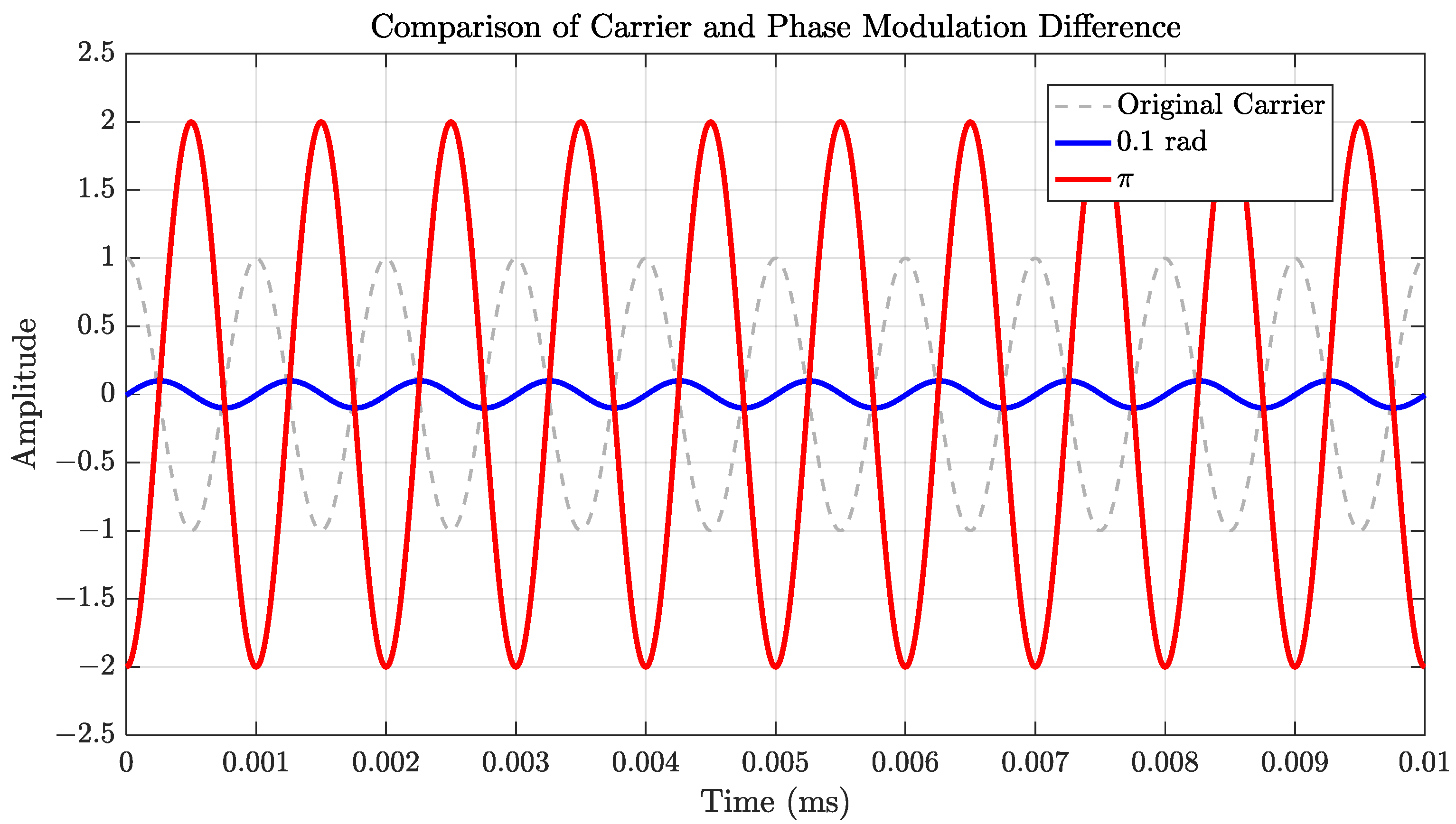
| Modulation depth | 0.1 rad | Gravitational wave design |
Disclaimer/Publisher’s Note: The statements, opinions and data contained in all publications are solely those of the individual author(s) and contributor(s) and not of MDPI and/or the editor(s). MDPI and/or the editor(s) disclaim responsibility for any injury to people or property resulting from any ideas, methods, instructions or products referred to in the content. |
© 2025 by the authors. Licensee MDPI, Basel, Switzerland. This article is an open access article distributed under the terms and conditions of the Creative Commons Attribution (CC BY) license (https://creativecommons.org/licenses/by/4.0/).
Share and Cite
Yu, T.; Long, H.; Xue, K.; Pan, M.; Wang, Z.; Liu, Y. Reconstruction and Separation Method of Ranging and Communication Phase in Beat-Note for Micro-Radian Phasemeter. Aerospace 2025, 12, 564. https://doi.org/10.3390/aerospace12070564
Yu T, Long H, Xue K, Pan M, Wang Z, Liu Y. Reconstruction and Separation Method of Ranging and Communication Phase in Beat-Note for Micro-Radian Phasemeter. Aerospace. 2025; 12(7):564. https://doi.org/10.3390/aerospace12070564
Chicago/Turabian StyleYu, Tao, Hongyu Long, Ke Xue, Mingzhong Pan, Zhi Wang, and Yunqing Liu. 2025. "Reconstruction and Separation Method of Ranging and Communication Phase in Beat-Note for Micro-Radian Phasemeter" Aerospace 12, no. 7: 564. https://doi.org/10.3390/aerospace12070564
APA StyleYu, T., Long, H., Xue, K., Pan, M., Wang, Z., & Liu, Y. (2025). Reconstruction and Separation Method of Ranging and Communication Phase in Beat-Note for Micro-Radian Phasemeter. Aerospace, 12(7), 564. https://doi.org/10.3390/aerospace12070564