1. Introduction
Hoisting equipment, especially the hoisting tools used for expensive or high-precision objects (such as satellites, aircraft, etc.), is indispensable auxiliary equipment in aerospace, weapons equipment, port transportation, and so on. They play an important role in leveling or adjusting posture during the hoisting process. Such objects generally have characteristics such as large structural weight, high requirements for smooth hoisting, an uncertain center of gravity, and high precision requirements for posture adjustment. At present, the hoisting equipment used in spacecraft generally has some problems, such as difficulty balancing operational performance and efficiency, over-reliance on manual experience, and a low degree of information and intelligence [
1].
In order to solve the above problems, it is necessary to research hoisting equipment that can achieve automatic adjustment. Currently, the equipment used for hoisting large objects is generally multiple mobile cranes, adopting a multi-point suspension mode and adjusting the posture depending on the movement of the crane. For example, Zi Bin et al. [
2] proposed a cable-driven parallel robot coordinated by four mobile cranes to solve complex tasks that a single crane is difficult to complete. The four-point collaborative leveling method is adopted for automatic leveling control for the CPRMC platform with a Proportional-Integral-Derivative (PID) controller. For conditions requiring single-point suspension, such as the indoor transfer or assembly of spacecraft, there are relatively few devices capable of automatic posture adjustment. According to the different leveling principles, automatic leveling robotic hoisting devices can be designed in various forms, such as main hoisting point mobile type [
3], rope direct connection type [
4,
5], and counterweight compensation type [
6,
7]. The main hoisting point mobile-type hoisting device achieves rapid adjustment of eccentricity through the movement of the main hoisting point, which can be realized using a two-dimensional sliding table structure [
8] or a cable-driven parallel mechanism [
9,
10,
11]. For instance, Tang et al. [
3] developed an automatic leveling hoisting device that uses a two-dimensional sliding table to achieve the movement of the main hoisting point. An XY workbench is installed to adjust the hoisting point of the spreader, and an inclination sensor is used to measure the size and direction of the spreader’s inclination accurately. Although the measurement of the angle and the adjustment distance have been realized automatically, operations such as controlling the overhead crane and holding the spacecraft tightly still need to rely on manual labor. The operation process is complicated, requires high technical skills from the operators, and cannot achieve dynamic continuous adjustment.
Italian scholar Carlo Ferraresi et al. [
12] designed a 9-rope 6-DOF cable-driven parallel mechanism, which can achieve 6-DOF posture adjustment of the motion platform. The spreader structure of the main hoisting point mobile type has the characteristics of a large adjustment range and quick posture adjustment. However, the movement of the main hoisting point requires the overhead crane to follow, which will bring a larger swing to the system and increase the operation difficulty. Rope direct connection type spreaders have the characteristic that the suspended object is directly connected with the adjusting ropes [
13]. For example, the feed flexible cable support system of a 500 m aperture spherical radio telescope (FAST) realizes the adjustments of position and posture of the end platform through a six-cable-driven parallel mechanism [
14]. The RoboCrane, which is applied to the hoisting work of large component assembly, adjusts the posture of the suspended movable platform through six paired connected ropes [
15]. This type of spreader has the characteristics of relatively simple structures, large load-bearing capacity, and high degrees of freedom, flexibility, and adaptability. Which is suitable for applications requiring rapid response and extensive motion range. However, when lifting heavy loads, larger adjustment forces are needed, and the elasticity and swinging of the ropes may result in unstable lifting operations, so additional control and adjustments are required [
16]. A counterweight-based spreader achieves posture adjustment through the movement of counterweights. For example, Zhang et al. [
17] proposed a 3D crane leveling mechanism based on weight compensation technology, which is composed of a crane, ropes, a leveling box, and four ropes of the same length. The leveling box is divided into three parts, with all sensors, motors, and microcomputers installed in the middle control part and two compensation weights, along with two beams, installed in the upper and lower execution parts, respectively. The adjustment of this type of spreader is safe and stable. However, with the increase in the weight of the suspended object, the compensation weight will significantly increase, so that the self-weight and dimensions of the spreader will increase.
Therefore, for the designer, it is essential to consider the advantages and disadvantages comprehensively in practical applications and carry out reasonable design and selection. Aiming at the hoisting requirement of spacecraft with an unknown center of mass, a rigid-flexible coupling cable-driven parallel robot spreader with a two-stage adjustment function combining the movement of the main hoisting point and counterweight is proposed in this paper. Its two-stage adjustment is realized through the cable-driven parallel mechanism and counterweight compensation mechanism. It has the characteristics of strong load-bearing capacity, a large workspace, easy reconfiguration, and flexible scale. The length of cables or the displacement of counterweights can be adjusted automatically based on the inclination angles, and the desired posture requirements can be achieved. This design can solve the problem of the insufficient automatic leveling ability of the existing automatic leveling robot. It is primarily used in the assembly, integration, and testing process of large spacecraft.
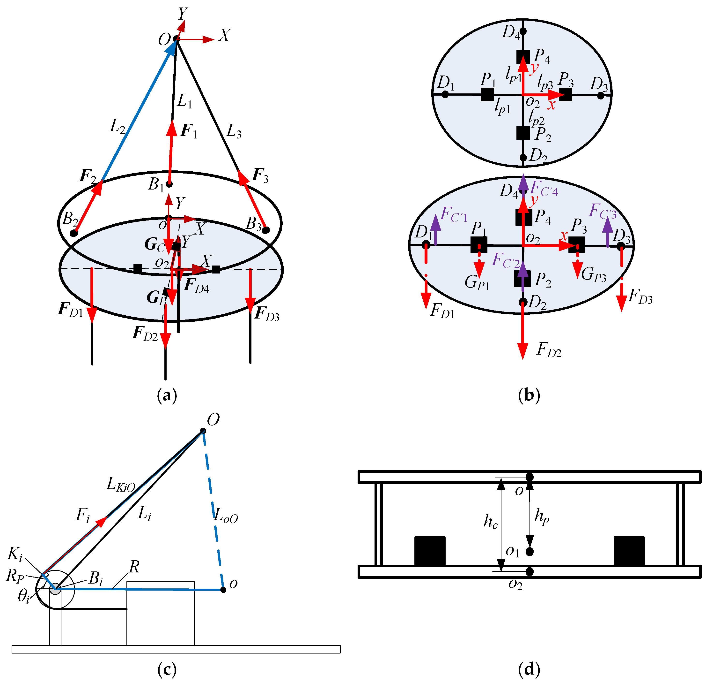
Kinematic analysis of a mechanism is the premise of determining its workspace, studying its posture and pose, analyzing its motion performance, and optimizing its design and control. The kinematic and dynamic analysis of cable-driven parallel robots is always a hot and challenging problem in mechanism research. The principle of virtual work, based on the principles of work and energy conservation, provides an accurate relationship between posture and joint angles [
18,
19]. Wang et al. [
20] proposed a cable-driven parallel mechanism with four sets of pulleys directly connected to the moving platform. The mapping matrix from the moving platform posture to cable lengths was derived by analyzing a single set of pulleys. Additionally, the velocity and acceleration formulas of the mechanism were solved according to the principle of virtual work. John et al. [
21] proposed a spatial cable-driven two-degree-of-freedom joint with variable stiffness capability and, based on the screw theory, thoroughly analyzed the joint mobility and workspace. Palpacelli [
22] enhanced the force controllability and static performance of industrial robots by introducing actuation redundancy to establish kinematic and static models. Jia et al. [
23] presented a method for solving the coupled cable-driven serial-parallel robotic arm using iterative Jacobian pseudoinverse computation. Li [
24] established the kinematic model and trajectory error of the end effector for parallel cable-driven robots using the closed vector method and the theory of differential kinematics. Chesser et al. [
25] utilized a cable-driven parallel robot for concrete additive manufacturing, establishing a kinematic model via the vector closure method, ultimately obtaining the reachable workspace of the end-effector. Through the analysis of the above methods, it can be observed that the closed vector method has the advantages of simplicity and convenience when analyzing the kinematics of cable-driven parallel mechanisms. In this paper, the kinematic model of the mechanism is established based on the closed vector method, and the positional solution is obtained. Then, an innovative approach is introduced to solve the adjustment amounts through torque balance equations. The required adjustment amounts when the mechanism reaches the given positions are derived from the difference in the positions of the counterweights between the current position and the critical equilibrium states, according to the balance assumption and steady-state approximation methods. The algorithm iterates according to the current inclination angles of the platform to eliminate the inevitable errors caused by flexible cables until the platform meets the predefined evaluation criteria.
The remaining sections of the article are outlined as follows: The second section mainly introduces the kinematic model of the mechanism. Firstly, the three-dimensional model and structural schematic of the cable-driven parallel automatic leveling robot are given, and the favorable position solution of the mechanism is derived using the closed vector method. Then, to ensure adjustment precision, an optimized adjustment scheme with the preferred selection of cables is proposed to ensure the stability of the spacecraft hoisting process. Finally, the adjustment amounts of the counterweights are solved based on force and torque balance equations, and the two-stage high-precision mechanism adjustment is completed. In the third section, MATLAB numerical calculations and ADAMS simulations are carried out on the automatic leveling robot model. In the fourth section, the experimental prototype has been built, and an experimental study has been carried out. The results validate the correctness of the leveling algorithm and the theoretical models.
3. Simulation Analysis of Cable-Driven Parallel Automatic Leveling Robot
To validate the effectiveness, feasibility, and correctness of the leveling algorithm, simulation analysis during the leveling process of the cable-driven parallel mechanism and counterweight compensation mechanism is conducted. For specific instances, MATLAB 2022a numerical calculations and ADAMS simulations are carried out. The structural parameters, mass parameters, and working loads applied to the four vertical suspension cables are shown in
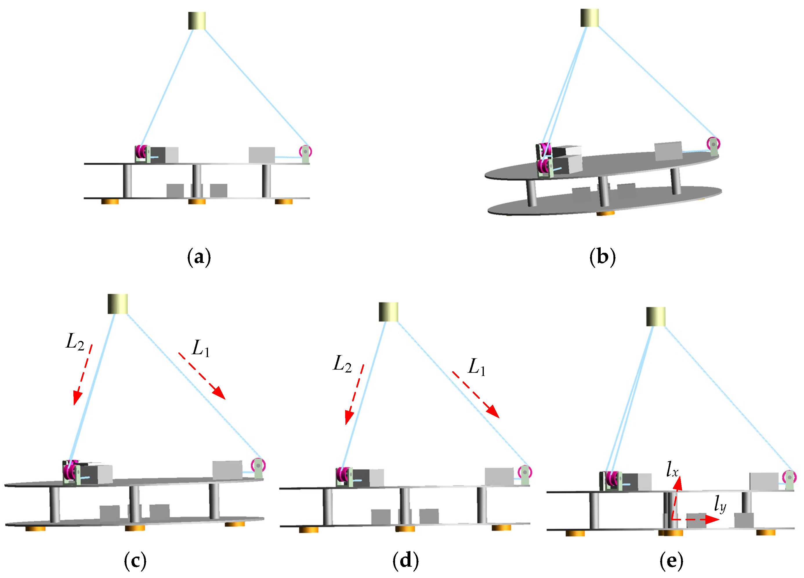
Table 1. The simulation model of the robot is established using ADAMS 2018 software, as shown in
Figure 4a. To simulate the posture after completely lifting the spacecraft, loads of magnitude
FD1 =
FD4 = 20 kN and
FD2 =
FD3 = 50 kN are added to the end of the four vertical suspension cables. The loads are applied in the vertically downward direction. The two-stage adjustment conversion threshold is set to 1°. After applying external forces, the moving platform inclines with angles
α = 4.817° and
β = 4.819°, as shown in
Figure 4b. The position and posture of the platform and the lengths of the inclined cables are measured and substituted into Equation (5) for calculation.
Based on the cable adjustment algorithm, the cable adjustment values are calculated in MATLAB, and the results are ∆
L1 = 191.38 mm, ∆
L2 = 143.86 mm, and ∆
L3 = 0 mm. According to this, by controlling the motion of the robot using these adjustments to the cables, the position and posture of the platform after the first adjustment of the inclined cables are shown in
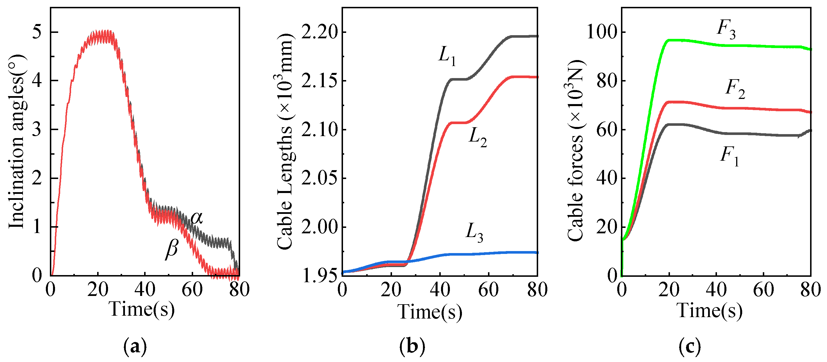
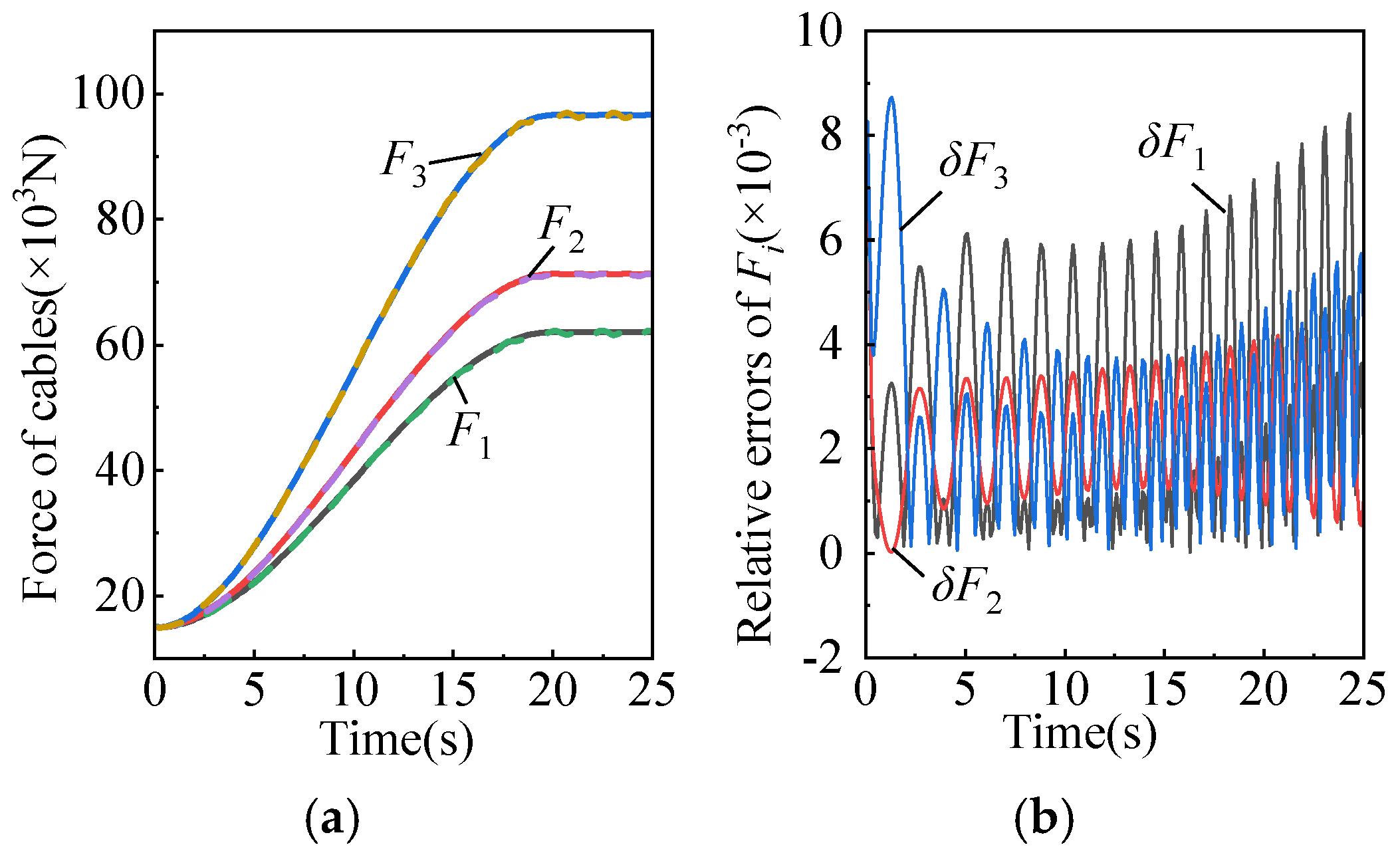
Figure 4c. The simulated measurement results are obtained in ADAMS by setting the corresponding parameters for the simulation. The curves depicting the changes in inclination angles, cable lengths, and cable forces are shown in
Figure 5. During the external force loading process, the variation of cable forces and the relative errors between analytical solutions and simulation solutions are shown in
Figure 6a,b, respectively, with a maximum relative error of less than 0.87%. The results are consistent. After the first adjustment of the cable-driven parallel mechanism, the calculated inclination angles of the moving platform become
α = 1.423° and
β = 1.339°, with a significant reduction. The platform posture is depicted in
Figure 4c.
At the end of one iteration of the cable adjustment, the system detects that the platform inclination has not reached the threshold of 1°, and the rope adjustment algorithm continues to work. The current posture information is recorded and based on the iterative calculation of the cable adjustment algorithm, the adjustment amounts for the cables are solved to be ∆
L1 = 62.122 mm, ∆
L2 = 47.135 mm, and ∆
L3 = 0 mm. The adjusted platform posture is shown in
Figure 4d. At this time, the inclination angles are
α = 0.658° and
β = 0.032°, which are below the set threshold. The system will exit the cable control loop and begin the counterweight adjustment algorithm. Based on the current posture, the adjustment amounts for the counterweights are calculated as ∆
lx = −25 mm and ∆
ly = 512.7 mm. The positions of the counterweights before and after adjustment are shown in
Table 2. After the counterweight adjustment, the inclination angles are
α = 0.103° and
β = 0.022°, and the platform posture is shown in
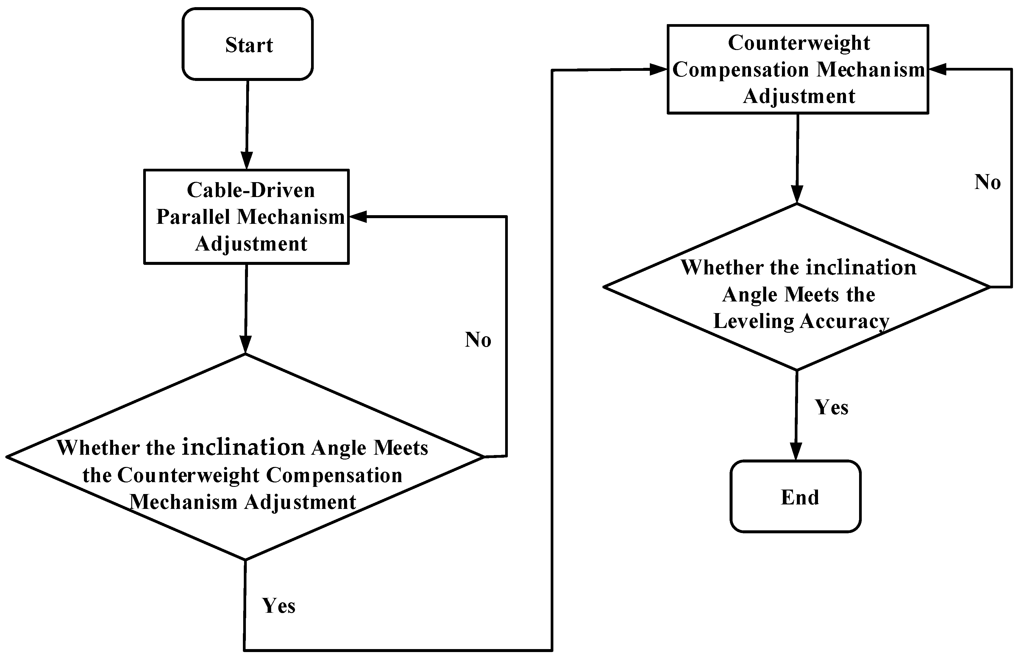
Figure 4e. This satisfies the horizontal accuracy required for the spacecraft hoisting. The counterweight adjustment is completed, and the system exits the loop. The postures of the moving platform during the two-stage adjustment are shown in
Table 3. To more clearly illustrate the two-stage adjustment process, a flowchart is presented in
Figure 7.
Based on the analyzed results, it is evident that the changes in cable lengths, platform angles, and cable forces during the adjustment process are in accordance with reality. The analytical values and simulated values of cable forces are in good agreement, and the curves are smooth. Here, due to the deformation of the cables and the flexibility of the system, there is a certain degree of error in the results, but it is within an acceptable range. This proves the correctness of the theoretical model and computational results. Also, it proves the feasibility of the proposed two-stage adjustment method.
4. Experimental Study of the Levelling System
The complete two-stage system, which includes both the cable-driven platform and the counterweight compensation mechanism, has been experimentally validated. The experiments were designed to comprehensively evaluate the leveling performance of both platforms within the proposed system. Specifically, the initial adjustment experiment of the cable-driven parallel mechanism and the accurate adjustment experiment of the counterweight compensation mechanism were conducted to demonstrate the feasibility and precision of the two-stage leveling approach.
4.1. Initial Adjustment Experiment of Cable-Driven Parallel Mechanism
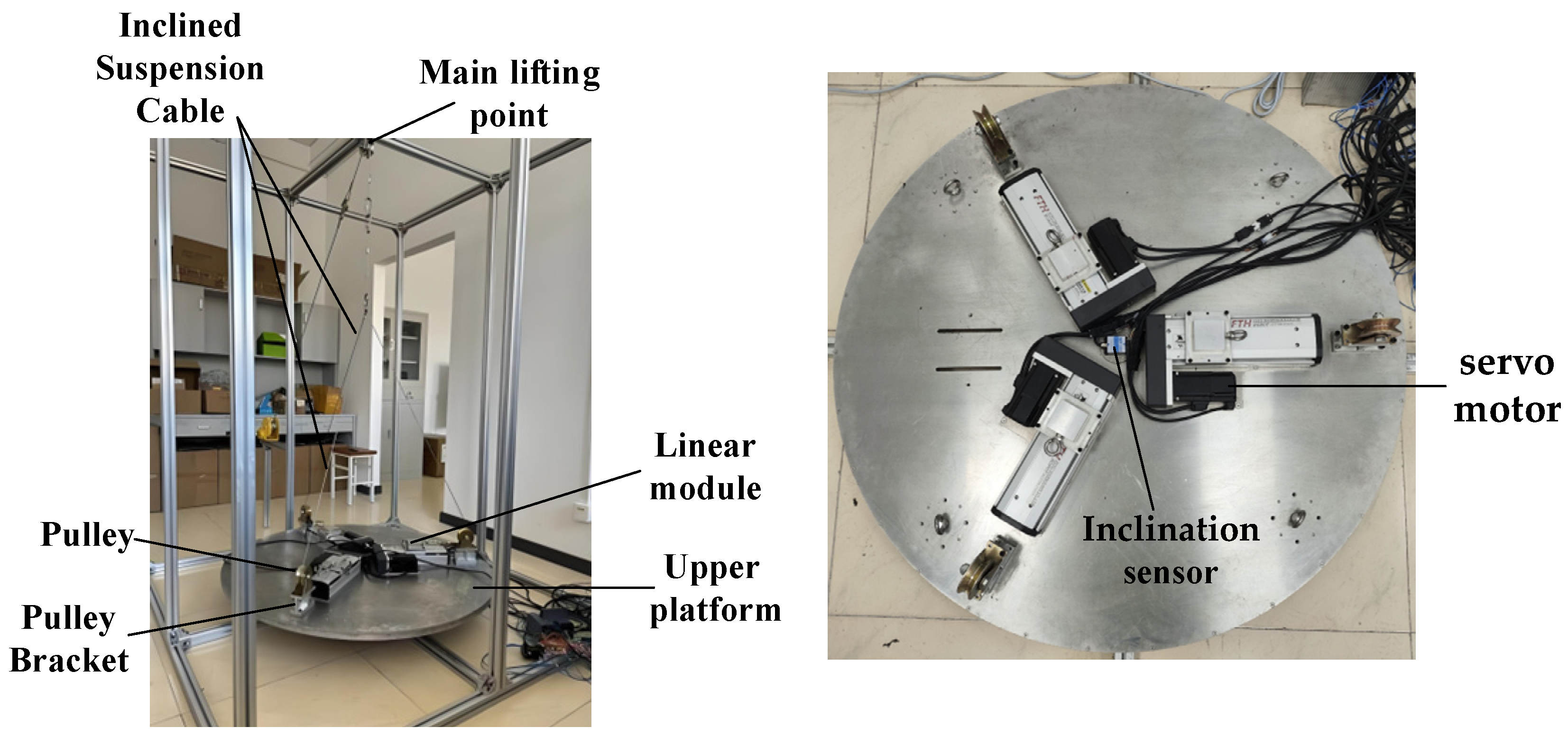
To further verify the practical application effect, the experimental prototype has been built. The prototype of the initial adjustment cable-driven parallel mechanism is shown in
Figure 8. Its moving platform is made of aluminum alloy. There are three linear modules driven by servo motors arranged at 120° on the moving platform and an inclination sensor arranged at the center. The posture of the suspended object is considered the same as the moving platform, so the angles measured by the sensor represent the posture of the suspended object. Each steel cable can be driven by the corresponding module, and the main lifting point can be changed by a winch. A PLC—Programmable Logic Controller—is used for motion control. The module displacement is precisely measured by receiving A/B phase pulses from the feedback of the servo motor so as to determine the cable length.
To verify the actual leveling performance of the designed robot, a dynamic hoisting and posture adjustment experiment has been conducted using a PID controller. During the experiment, set the eccentricity randomly, then lift the device upward slowly. In this process, values of the inclination sensor are read and recorded in real time, and the posture of the moving platform is adjusted through the designed control system when the inclination angles exceed ± 1°. The adjustment will be finished when the platform is fully off the ground and the inclination angles remain within the target range.
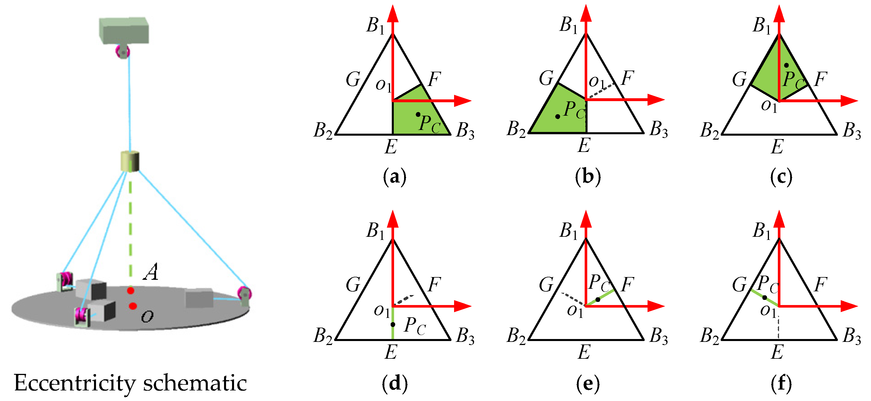
Here, two sets of experiments are conducted, shown as situations a and b.
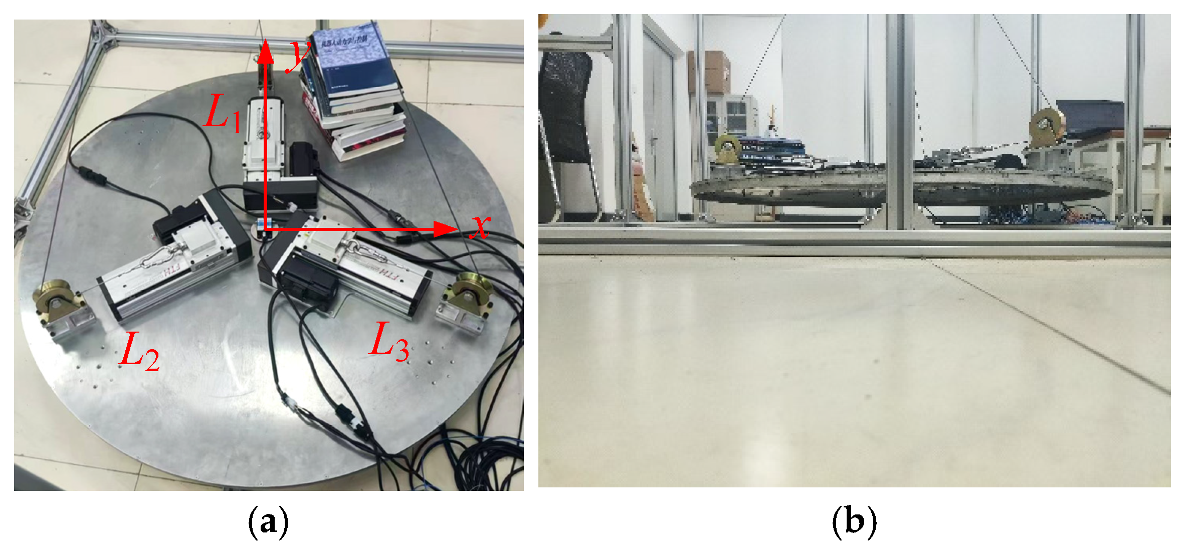
Situation a. The eccentric position PC (x, y) satisfies , and .
The experimental model is shown in
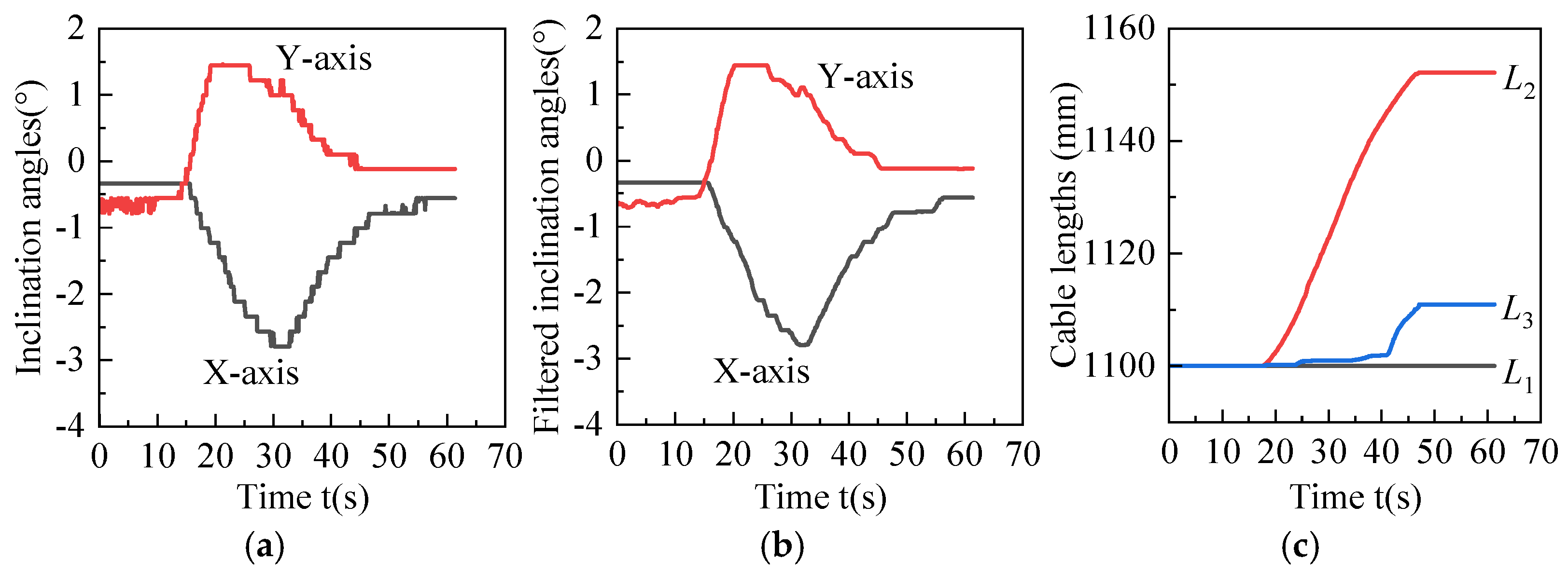
Figure 9a,b. In this situation, according to the adjustment algorithm, Δ
L1 is set to 0, and the lengths of
L2 and
L3 should be adjusted. During the adjustment, the angle values of the inclination sensor before and after filtering are shown in
Figure 10a,b, and cable lengths are shown in
Figure 10c. After adjustment, the values of the inclination sensor are stable within ±1°, which is consistent with reality.
Situation b. The eccentric position PC (x, y) satisfies:, .
The experimental model is shown in
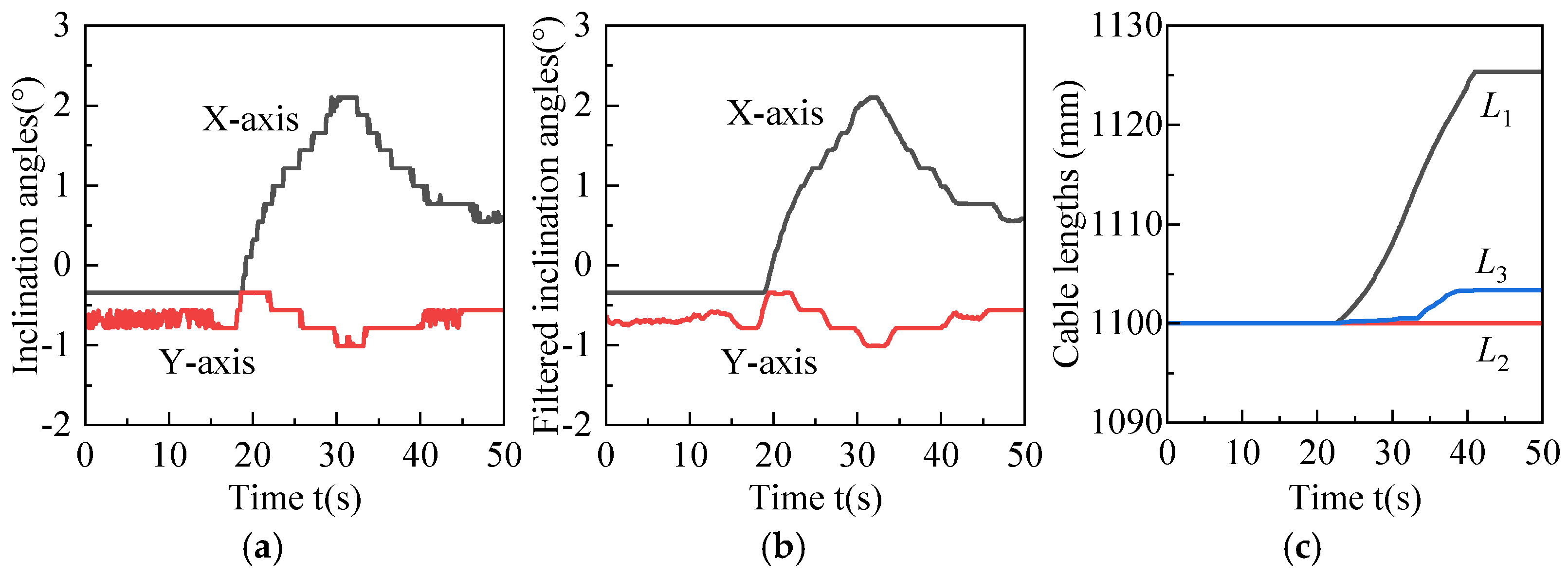
Figure 11a,b. In this situation, Δ
L2 is set to 0, and the lengths of
L1 and
L2 should be adjusted. During the adjustment, the angle values of the inclination sensor before and after filtering are shown in
Figure 12a,b, and cable lengths are shown in
Figure 12c. After adjustment, the values of the inclination sensor are stable within ±1° too.
The results show that for situation a, the angles of the X-axis changed from a maximum of −2.79° to a stable −0.56°, and the angles of the Y-axis changed from a maximum of 1.44° to a stable −0.12°. During this process, the length of cable L1 remained constant, the length of cable L2 increased from 1100 mm to 1152.11 mm, and the length of cable L3 increased from 1100 mm to 1110.96 mm. For situation b, the angles of the X-axis changed from a maximum of 2.10° to a stable −0.59°, and the angles of the Y-axis changed from a maximum of −1.01° to a stable −0.56°. During this process, the length of cable L3 remained constant, the length of cable L1 increased from 1100 mm to 1125.38 mm, and the length of cable L2 increased from 1100 mm to 1103.37 mm. Experimental validation confirms the accuracy of the theoretical model.
4.2. Accurate Adjustment Experiment of Counterweight Compensation Mechanism
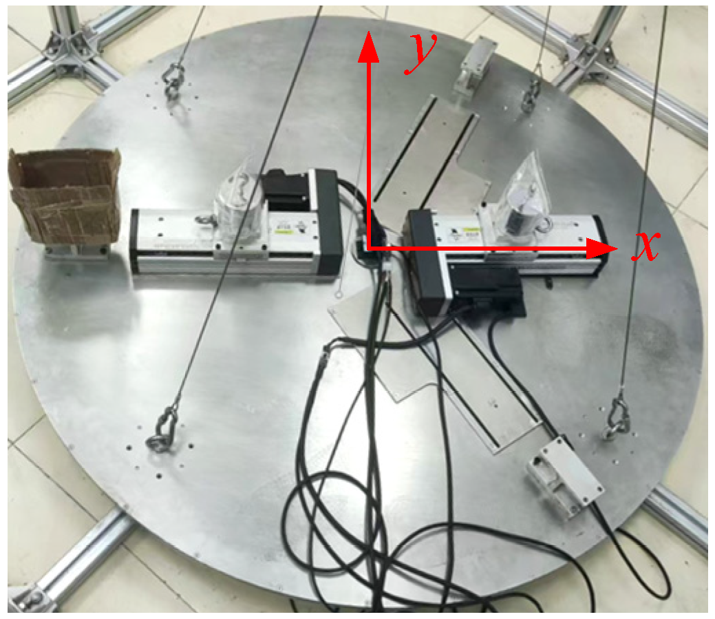
To verify the actual leveling performance of the counterweight compensation mechanism, this study further conducts dynamic adjustment experiments on the counterweight compensation prototype using a PID controller. The experiment prototype model is shown in
Figure 13.
Because of the symmetry and independence of the X-axis and Y-axis in the adjustment algorithm, there are only two linear modules arranged in the X direction to save costs. Actually, it can verify the feasibility. There are four fixed cable lengths connecting the main hoisting point and the moving platform. One counterweight of 2 kg is arranged on each linear module. When the linear module moves, the counterweight moves with it. Based on the counterweight adjustment algorithm, a PLC program is written to control the movement of the linear modules. The adjustment is considered to be finished when inclination angles are stable within 0.11°. The initial position of each counterweight is 50 mm away from the bottom of the corresponding module. Two modules move synchronously.
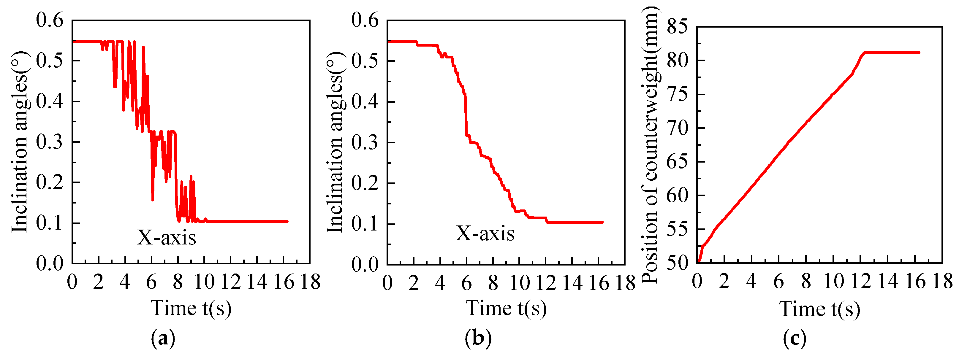
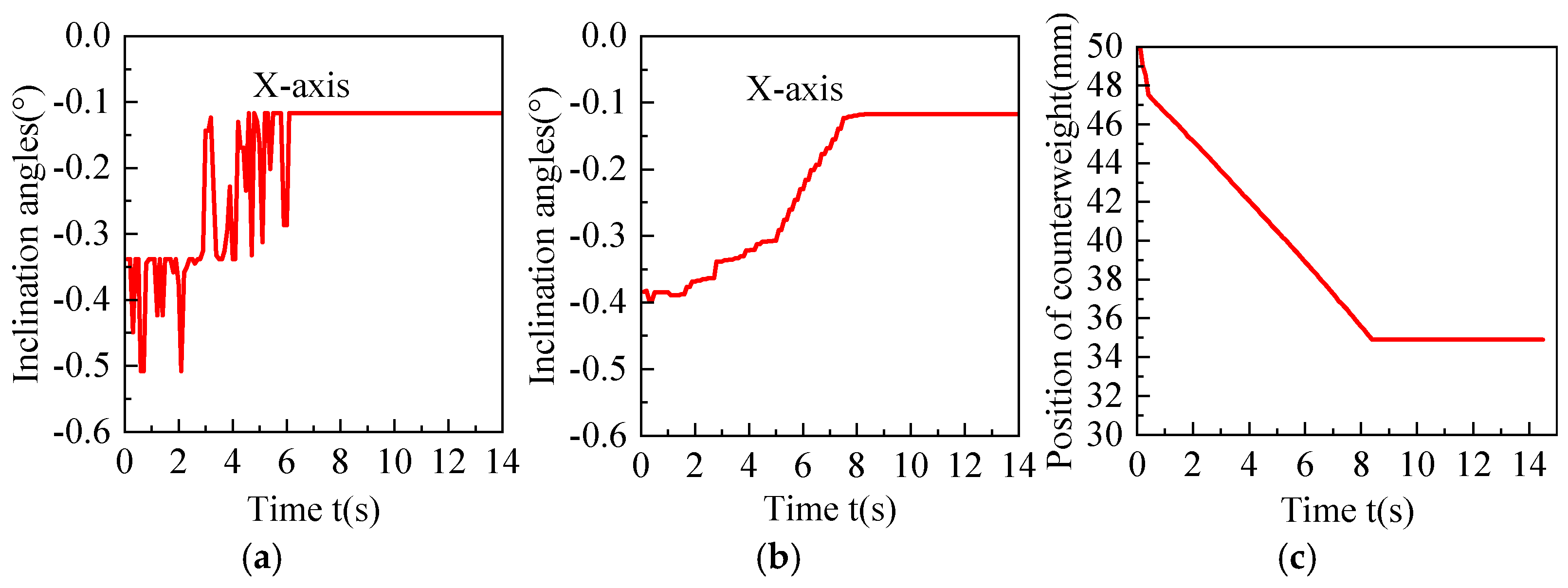
In order to better observe the leveling effect, the moving platform is lifted in a fully suspended state. Here, two sets of experiments are conducted with two different situations. One is an initial inclination angle of 0.55° in the X direction. The other is an initial inclination angle of −0.34° in the X direction. During the experiment, the angle values of the inclination sensor before and after filtering of the two situations are shown in
Figure 14a,b and
Figure 15a,b, respectively. The counterweight positions are shown in
Figure 14c and
Figure 15c.
In the first situation, inclination angles vary from 0.55° to 0.11°, and counterweight position has changed from 50 mm to 81.16 mm. In the second situation, inclination angles vary from −0.34° to −0.11°, and counterweight position has changed from 50 mm to 34.89 mm. Both positive and negative inclinations in the X direction can realize the requirement adjustment. The threshold judgment prevents overshooting and oscillations. Although there exists noise and delay in the PLC signal acquisition, the angle values after moving average filtering can be used for smooth adjustment.
_Zhu.png)


