Article

Space Demonstration of All-Solid-State Lithium-Ion Batteries Aboard the International Space Station

1
Japan Aerospace Exploration Agency, 3-1-1 Yoshinodai, Sagamihara 252-5210, Kanagawa, Japan
2
Japan Aerospace Exploration Agency, 2-1-1 Sengen, Tsukuba 305-8505, Ibaraki, Japan
3
Kanadevia Corporation, 2-2-11 Funamachi, Osaka 551-0022, Osaka, Japan
*
Authors to whom correspondence should be addressed.
Current address: Laboratory of Lean Satellite Enterprises and In-Orbit Experiments, Kyushu Institute of Technology, Kitakyushu 804-8550, Fukuoka, Japan.
Aerospace 2025, 12(6), 514; https://doi.org/10.3390/aerospace12060514
Submission received: 16 April 2025 / Revised: 28 May 2025 / Accepted: 2 June 2025 / Published: 6 June 2025
(This article belongs to the Section Astronautics & Space Science)

Abstract

All-solid-state lithium-ion batteries (ASSBs) have a wide operating temperature range (−40 °C to +120 °C) and are expected to be applied to lunar exploration, which has become increasingly active in recent years. Since a ground development test confirmed that ASSBs are tolerant of the space environment, in this study, a space demonstration test is conducted on the International Space Station (ISS). The battery was exposed in the ISS Exposed Section for 434 days. A total of 562 charge–discharge cycle tests were conducted, in addition to basic charge–discharge characterization, with no significant degradation observed in the charge–discharge characteristics or battery appearance. These results confirm that the battery operates reliably even in a complex space environment. This test confirmed that the lifetime characteristics of ASSBs can be estimated via ground-based charge–discharge characteristics, encouraging their potential application in space exploration.

1. Introduction

Lunar exploration has been particularly active in recent years, with the Artemis Project announced by the U.S. for manned lunar exploration in 2019 [1]. Beyond lunar exploration, future missions are increasingly considering Mars as the next target [2]. The technologies, operational experiences, and scientific insights gained from lunar missions are expected to serve as a foundation for developing the systems and strategies necessary for Martian exploration.
There are two main candidates for energy storage for lunar and Martian exploration: (1) chemical (batteries) and (2) nuclear (e.g., radioisotope thermoelectric generators or nuclear batteries) [3]. Among these, rechargeable batteries are indispensable for exploration because they can be easily expanded from small to large capacities while ensuring safety. At the lunar equator, daytime maximum temperatures can exceed 120 °C, while they can drop to −170 °C or lower just before sunrise [4]. On the Martian surface, temperatures can rise to approximately 20 °C during the day and decline to −120 °C or lower at night, depending on local conditions and season [5]. Therefore, equipment used on the Moon or Mars must be designed to withstand extreme temperature conditions. Although lithium-ion rechargeable batteries (LE-LIBs), which incorporate organic solvents as electrolytes and offer higher energy density than Ni-Cd and Ni-H2 batteries, are the primary rechargeable batteries used in spacecraft, their limited temperature range makes their long-term use on the Moon and Mars difficult, even with thermal control. For future Mars missions, the application of lithium–carbon dioxide (Li–CO2) batteries [6,7], which utilize the abundant CO2 in the Martian atmosphere, is being explored as a potential energy storage solution.
In recent years, all-solid-state lithium-ion rechargeable batteries (ASSBs) incorporating solid electrolytes [8,9] have attracted attention because of their wide operating temperature range, good safety, long lifespan, and high energy density on the ground. Since flammable organic solvents are used as the liquid electrolyte in general LE-LIBs, this poses risks such as marked reductions in service life, rupture, or ignition due to electrolyte gasification at high temperatures. At low temperatures, the electrolyte may solidify, leading to lithium deposition; therefore, the operating temperature range in practical use is limited to 5–40 °C for both safety and performance reasons [10]. In contrast, ASSBs with solid electrolytes that are stable across a wide operating temperature range can achieve greater safety, longer lifespan, and higher energy density than LE-LIBs. This is primarily because solid electrolytes are less prone to side reactions with other materials, along with their ability to extend the operating temperature range [9].
This study evaluates the space environment resistance of ASSBs, including their tolerance to a wide operating temperature range, focusing on applications to the harsh conditions of the lunar surface. In space, where repairs and immediate replacements are challenging, a two-fault tolerant design is required for the use of LE-LIBs, particularly in human spaceflight. However, high-safety ASSBs have the potential to simplify battery protection circuits, which can contribute to improved system reliability and reduced complexity. After confirming their potential for space exploration by evaluating temperature resistance, vacuum resistance, mechanical durability on the ground, and gamma-ray radiation, as described in Section 2, the world’s first demonstration in space was conducted, exposing the ASSBs to the combined effects of a wide temperature range, high vacuum, radiation, and microgravity. Consequently, this study confirmed that the ASSBs exhibit good charge–discharge characteristics both in space and on the ground.

2. Fundamental Properties of All-Solid-State Lithium-Ion Batteries

In this section, the fundamental properties of solid-state lithium-ion batteries and the results of space environment durability evaluations are discussed. Solid-state electrolytes are broadly classified into sulfide-type and oxide-type materials, each with distinct advantages and challenges [11]. Sulfide-type electrolytes offer high ionic conductivity at room temperature and good processability, making them suitable for constructing high-capacity ASSBs. In contrast, oxide-type electrolytes exhibit higher chemical stability and safety; however, they typically require high-temperature processing and have relatively lower contact performance with electrodes, which complicates the fabrication of large-capacity cells. Due to these challenges, particularly the difficulty in scaling up oxide-type ASSBs to several Ah capacities, sulfide-type electrolyte systems currently lead the development of practical ASSBs for early lunar applications. Therefore, this study focused on sulfide-type ASSBs, which have shown promising progress toward practical-scale fabrication. Prior to the comprehensive evaluation of space environment resistance reported in this study, a similarly designed ASSB demonstrated only a 5% decrease in capacity after 5000 charge–discharge cycles at 25% depth of discharge (DOD) under room temperature and was also confirmed to be capable of discharging at a low temperature of −50 °C [12].
Figure 1 illustrates their appearance. Table 1 lists the specifications of the ASSBs for the space demonstration, while the 140 mAh-class ASSBs are all-solid-state lithium-ion batteries that use a ternary material (nickel–cobalt–manganese) as the cathode, a graphite-based anode, and a sulfide-type solid electrolyte. As shown in Table 1, the upper limit of the operating temperature range is +120 °C, which closely corresponds to the maximum temperature on the lunar surface. The specified charging rate for the battery is 0.1 C, and increasing the charge rate remains a challenge for future research. However, in this study, we have evaluated the performance of the battery under higher charging rates such as 0.2 C and 1 C. The characteristics of this battery are presented in Section 2.1 and in subsequent sections. The batteries employed in this study were the same as those employed in the space demonstration described in Section 3.

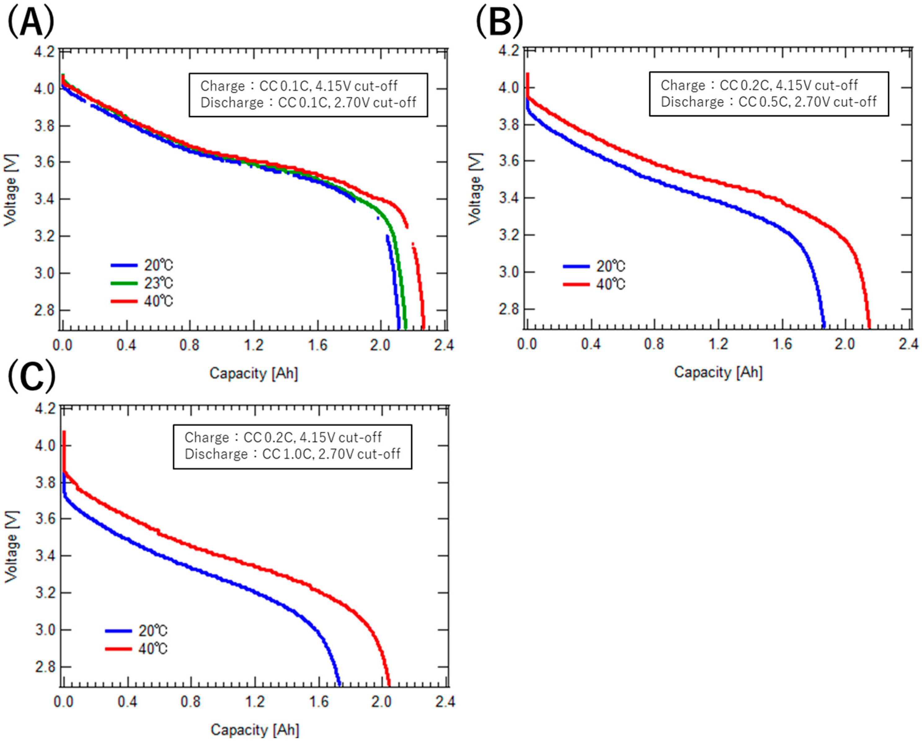
2.1. Charge–Discharge Characteristics

Figure 2A shows the temperature dependence of the ASSB discharge characteristics. Charging was conducted at 25 °C under a constant current (CC) of 0.1 C. The discharge was conducted at a CC of 0.1 C with a cut-off voltage of 2.7 V. From 25 °C to 60 °C, the discharge capacity increases with higher temperatures due to a reduction in internal resistance. However, at temperatures above 80 °C, a slight decrease in discharge capacity is observed; however, within the temperature range of 25 °C to 120 °C, the difference in discharge capacity remains within 5%, indicating stable discharge characteristics. Below 0 °C, the discharge capacity significantly decreased because of the increase in internal resistance. However, even at −40 °C, more than 30% of the discharge capacity at 25 °C can be obtained, indicating that the battery remains dischargeable. Discharge characteristics below −40 °C have not been obtained; however, a further increase in internal resistance at such low temperatures is expected to result in a more pronounced voltage drop.
Figure 2B illustrates the rate dependence of the discharge current at 25 °C. The charging current was uniformly set to 0.1 C, with a cut-off at 4.15 V. The discharge characteristics were compared by varying the discharge current to 0.1 C, 0.2 C, 0.4 C, 0.5 C, and 1.0 C. The capacity retention rate was 90% at 0.5 C and 83% at 1 C, relative to the rate at 0.1 C.
Figure 3 shows the capacity retention during continuous charge–discharge cycles at 25 °C. The conditions for continuous charge–discharge cycling were as follows: the charging current was 0.2 C with a cut-off of 4.15 V, and the discharge current was 0.5 C with a cut-off of 2.70 V. Capacity checks were conducted every 50 cycles at a rate of 0.1 C for both charging and discharging. After 500 cycles, the ASSB retained over 97% of its initial capacity, demonstrating excellent charge–discharge cycle characteristics.

2.2. Environmental Tests

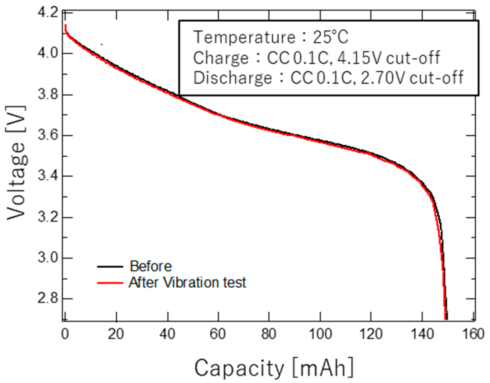
2.2.1. Vibration Tests

A vibration test was conducted to evaluate the tolerance of ASSBs to the vibrations experienced during the rocket launch phase. Table 2 lists the conditions of the sinusoidal and random vibration tests. The vibration test was conducted in all axial directions (X, Y, and Z), with the same conditions for each axis. These conditions were set based on those expected for components of satellites mounted on a typical launch vehicle, such as the H-IIA rocket. Assuming that the battery was in a fully charged, non-operational state during launch, the test was conducted at a 100% state of charge under open-circuit conditions. Figure 4 shows the discharge characteristics before and after the vibration tests. Because the sinusoidal and random vibration tests were conducted consecutively, the discharge characteristics were obtained before and after both tests. Because there was no significant change in the discharge profile and appearance of the ASSB, it was confirmed that the ASSB was tolerant of the vibrations experienced during the rocket launch. Ensuring vibration tolerance in LE-LIBs is challenging because the electrode mass inside the battery is not fixed within the casing. In contrast, ASSBs are expected to have better vibration tolerance since their internal electrodes remain stationary.

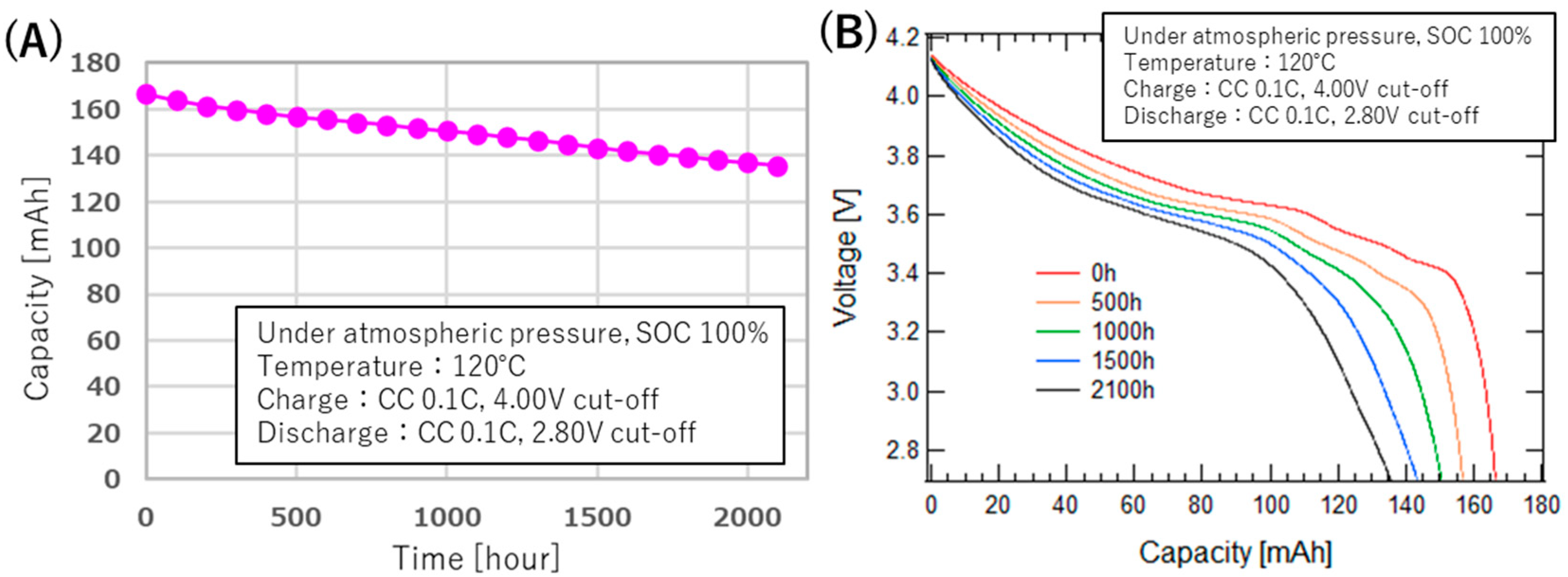
2.2.2. High-Temperature Storage Tests

To simulate daytime conditions on the lunar surface, the high-temperature exposure resistance of the ASSB was evaluated at 120 °C. The discharge capacity at 120 °C was assessed every 100 h. The changes in the discharge curves are shown in Figure 5A, and the transition in the discharge capacity is presented in Figure 5B. An exposure of 2100 h at 120 °C was conducted, corresponding to the equivalent of half a year of daytime activity on the lunar surface. After 2100 h of storage at 120 °C, the ASSB retained 81% of its initial capacity. The capacity degradation rate remained approximately constant for up to 2100 h, remaining below 1% per 100 h. Additionally, even after 2100 h of storage, no significant changes were observed in the discharge curve of the ASSB, which discharged more than 81% of its initial capacity. This indicates the potential of the ASSB to provide stable power during the 14-day high-temperature daytime period on the Moon without the need for specialized thermal control.

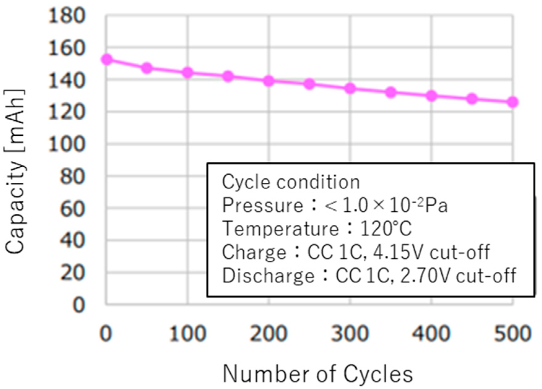
2.2.3. High-Temperature Charge–Discharge Tests Under Vacuum

Figure 6 presents the capacity retention rate during continuous charge–discharge cycles at 120 °C under vacuum. The conditions for the continuous charge–discharge cycling were as follows: the charging current was 1 C with a cut-off at 4.15 V, and the discharge current was 1 C with a cut-off at 2.70 V. Capacity checks were conducted every 50 cycles at a rate of 0.3 C for both charging and discharging. Considering that 120 °C is a temperature at which LE-LIBs cannot undergo even a single charge–discharge cycle, the fact that the ASSB maintains more than 82.6% of its capacity after 500 cycles indicates exceptional high-temperature cycle durability.

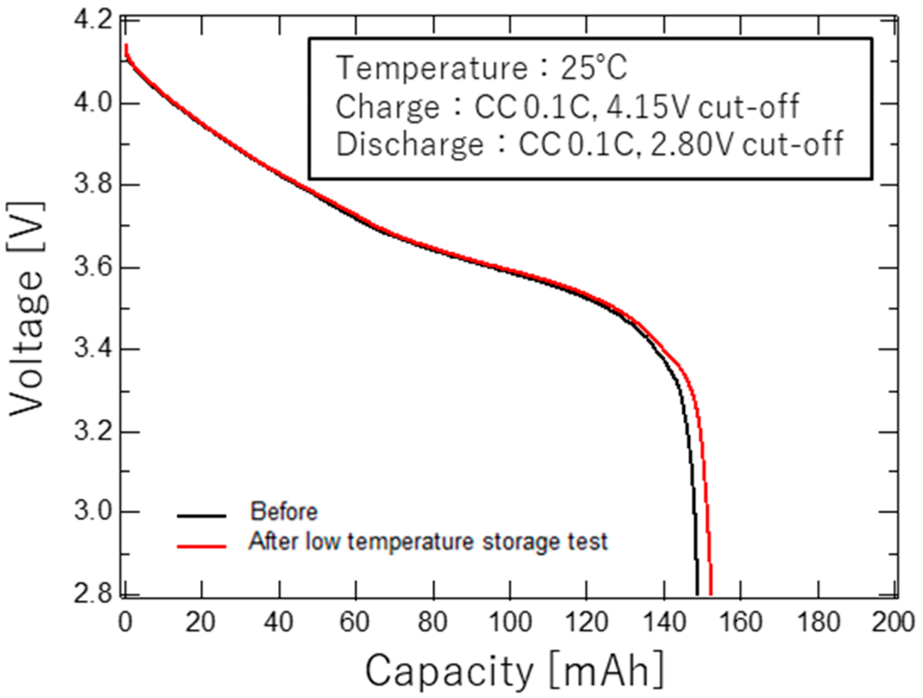
2.2.4. Low-Temperature Storage Tests

As demonstrated in Figure 2, the internal resistance of ASSBs increases significantly at low temperatures, resulting in a larger voltage drop. Hence, the operational discharge temperature range for ASSBs is limited to above −40 °C. During eclipse periods, it is feasible to maintain the battery temperature above −40 °C using insulation or thermal control. However, if thermal control is not possible due to energy conservation measures or power shortages, the temperature may drop below −40 °C. The low-temperature storage performance of ASSBs was evaluated by assessing the discharge characteristics after 800 h of exposure to −100 °C. As shown in Figure 7, no abnormalities were observed in the discharge characteristics at 25 °C before and after exposure to −100 °C, and no degradation in capacity was detected. Owing to the absence of the electrolyte phase-change mode resulting from the solid electrolyte, ASSBs exhibit minimal structural changes even at low temperatures, indicating a high potential to withstand the harsh nighttime lunar conditions.

2.2.5. Simulated Lunar Surface Operation Test

The anticipated use of batteries on the lunar surface involves charging during the 14-day daytime period and discharging during the subsequent 14-day eclipse period to power devices and heaters. To simulate these lunar operations, a lunar operation simulation test involving high-temperature charging and low-temperature discharging was conducted. Considering the operating temperature range of the ASSB and the lunar environment, the charging temperature was set to +120 °C, while the discharging temperature was set to −40 °C. Additionally, since recharging was not possible during the 14-day eclipse period when the power source was a solar panel, the discharge rate during the eclipse was expected to be low. Therefore, we set the charging current to 0.1 C with a cut-off of 4.00 V, and the discharge current to 0.05 C with a cut-off of 2.80 V. Due to limitations of the measurement equipment, the voltage range used in this test differs from that used in the other experiments. A total of 12 charge–discharge cycles, equivalent to one year of lunar operation, were performed to evaluate the charge–discharge cycle characteristics. Although lunar exploration is being actively studied, long-duration missions powered by non-nuclear energy sources have not yet been realized. Therefore, the duration of this study was set to one year, aiming to enable a one-year operation as a first step.
The discharge characteristics of each cycle are presented in Figure 8. Due to the discharge rate of 0.05 C and the high charging temperature, the discharge capacity during the first cycle was more than 10% higher than the discharge capacity at −40 °C shown in Figure 2. Although the discharge capacity decreased with each cycle, more than 70% of the first cycle capacity was retained after 12 cycles. This indicates that ASSBs have the potential to be suitable for one year of lunar operation. Because simulated charge–discharge cycling equivalent to one year on the lunar surface showed significant capacity degradation, future investigations will require SEM, EDS, and XPS analyses to elucidate the degradation mechanisms.

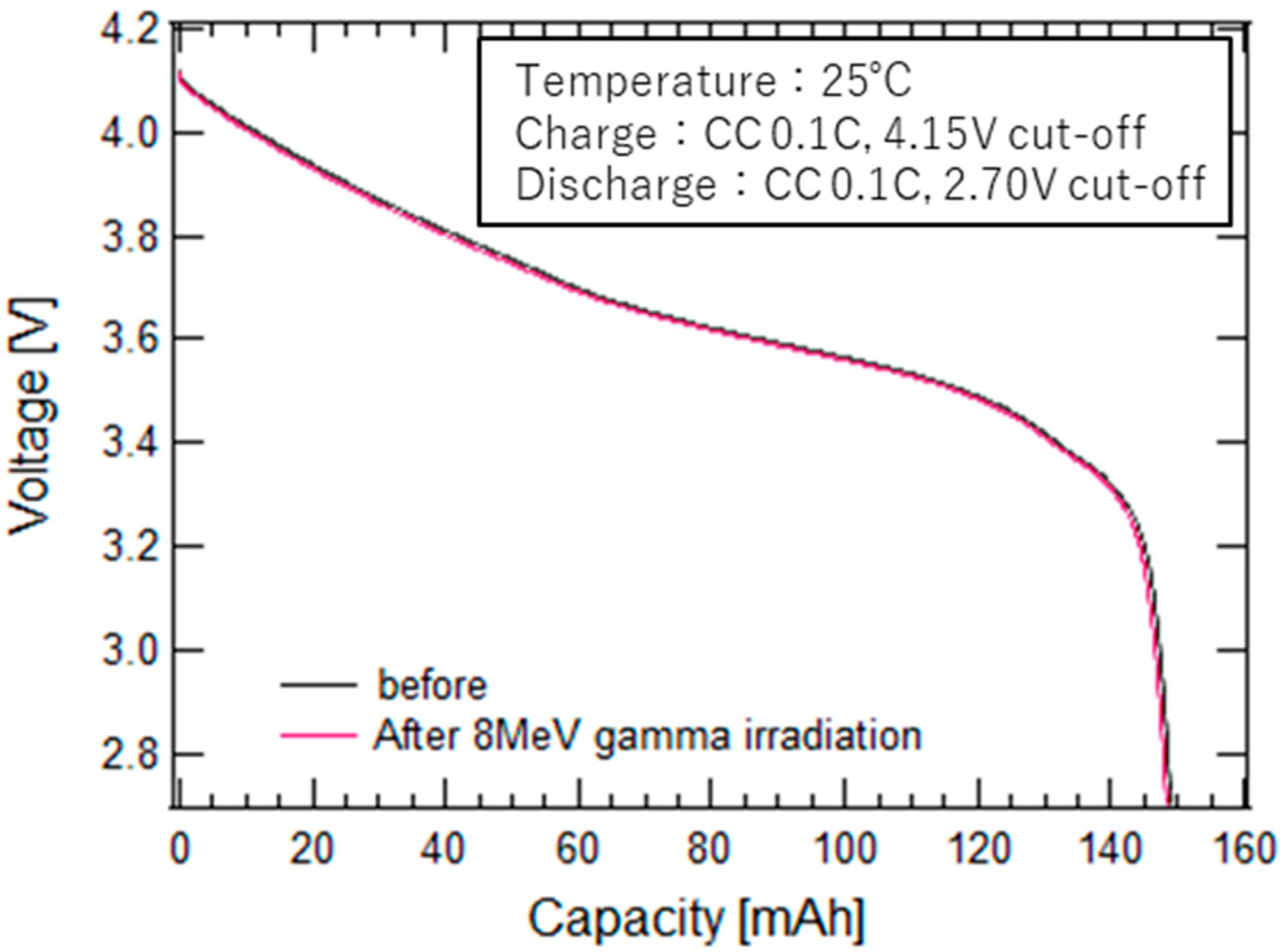
2.2.6. Gamma-Ray Irradiation Test

In space, the absence of geomagnetic shielding results in significantly greater exposure to high-energy radiation, such as electrons and protons, compared to conditions on Earth. Therefore, components and materials used in spacecraft are required to possess high radiation tolerance [14,15]. Although a clear correlation between total ionizing dose and degradation has not been established for conventional LE-LIBs used in space applications, a study has reported more than a 10% degradation in discharge capacity after exposure to 0.8 Mrad of gamma-ray radiation [16].
To evaluate the radiation tolerance of ASSBs, gamma-ray irradiation tests were conducted on individual cells at dose levels of 2 Mrad and 8 Mrad, and the impact on electrical performance was assessed based on the discharge characteristics before and after irradiation. The discharge characteristics before and after 8 Mrad gamma-ray irradiation are presented in Figure 9. No abnormalities were observed in the discharge characteristics at 25 °C before and after gamma-ray exposure to radiation levels up to 8 Mrad. The capacity retention of the ASSB after exposure to 2 Mrad was 99.6%, and a similar retention of 99.6% was observed even after 8 Mrad exposure, suggesting that there was no significant degradation associated with the increased gamma-ray radiation dose. Considering that the total radiation dose over ten years is estimated to be less than 1 krad both in low Earth orbit [17] and on the lunar surface [18], it can be concluded that the ASSBs pose no issues in terms of radiation tolerance for space applications.

3. Space Demonstration Experiment

3.1. Overview of the Space Demonstration Experiment

The space demonstration of ASSBs, the characteristics of which are introduced in Section 2, was conducted on the Exposed Section of the International Space Station (ISS) using the Japanese Experiment Module “Kibo”. The primary objective of this demonstration was to evaluate the charge–discharge characteristics of ASSBs under space conditions, including exposure to radiation and vacuum, and to determine whether degradation modes are specific to space conditions, as opposed to those observed on Earth. Because battery failure directly equates to mission failure, approved reliability is a critical requirement for batteries used in spacecraft applications. This stringent reliability requirement often makes it challenging to adopt new battery technologies, underscoring the importance of space demonstrations for such innovations. As an evaluation method for the charge–discharge characteristics in orbit, two cells from the same lot as the ASSB used in orbit were tested under the same operational conditions at atmospheric pressure on the ground. The obtained characteristics were then compared.
To achieve a battery capacity suitable for practical applications, a 2.1 Ah battery pack was constructed using 140 mAh ASSBs in a configuration of 15 parallel connections. An image of the battery is presented in Figure 10A. Figure 10B illustrates an image and the appearance of the all-solid-state lithium-ion battery on-orbit demonstration device (Space AS-LiB) equipped with the 2.1 Ah battery pack. Space AS-LiB was installed on the Small Payload Support Equipment (SPySE), an extension module of the i-SEEP platform attached to “Kibo.” SPySE provided power and communication links between the ISS and Space AS-LiB. Space AS-LiB features the following functionalities:
  • Charging function: CC charging control at rates of 0.1 C and 0.2 C.
  • Discharge function: Constant resistance discharge control at rates of 0.1 C, 0.5 C, and 1.0 C.
  • Continuous charge–discharge operation.
  • Battery safety protection: Overcurrent protection, overcharge protection, and overdischarge protection.
  • Battery temperature control function.
  • The 360° camera imaging function, powered by the demonstration battery.
  • Power and communication interface functions with ISS/SPySE.
Figure 10. (A) Image of the battery demonstrated in space. (B) Image and illustration of the all-solid-state lithium-ion battery on-orbit demonstration device.
Aerospace 12 00514 g010

3.2. Operation of the Space Demonstration

The Space AS-LiB was launched aboard an NG-17 rocket in February 2022 and subsequently installed in the Exposed Section of the ISS. Figure 11 presents an image of the Space AS-LiB installed on the SPySE (Small Payload Support Equipment). Through SPySE, ground commands were transmitted to Space AS-LiB to operate its charge–discharge control circuit and heater control circuit, enabling the evaluation of the charge–discharge characteristics of the ASSB battery. A total of 11 test conditions were established to evaluate the fundamental charge–discharge characteristics, as well as to assess the continuous charge–discharge cycle performance for lifespan evaluation. At the time this experiment was conducted, no prior data existed regarding the charge–discharge performance of ASSBs in the space environment. Therefore, to evaluate the effects of rate and temperature characteristics, charge–discharge tests were conducted under multiple conditions, taking into account the operational constraints of the ISS demonstration platform. Although it is challenging to obtain multi-year cycling data required for actual space missions through space demonstrations, the objective was to acquire several hundred charge–discharge cycles, which is sufficient for comparison with ground-based test results. The specific conditions for acquiring the charge–discharge characteristics are listed in Table 3. Although certain test conditions exceeded the recommended charging current of the ASSBs listed in Table 1, they were set considering their applicability to on-orbit operations. In addition, a 360° camera was operated using power from the battery to capture images of the ISS surroundings. It was confirmed that the system could supply power to constant and variable loads. During the demonstration test, the system was temporarily stored inside the ISS due to SPySE constraints but was exposed to the external environment for a total of 434 days.

4. Results

4.1. Fundamental Charge–Discharge Characteristics

The discharge curves obtained in orbit at varying battery temperatures, charge rates, and discharge rates are presented in Figure 12. Figure 12A shows the 0.1 C discharge curves following 0.1 C charging at battery temperatures of 20 °C, 23 °C, and 40 °C. As predicted from the temperature dependence of the discharge characteristics, the discharge capacity increased at higher battery temperatures. The respective discharge capacities were 2.11 Ah, 2.16 Ah, and 2.27 Ah. As illustrated in Figure 12B,C, the 0.5 C and 1.0 C discharge characteristics indicate that the initial voltage drop upon discharge commencement becomes more pronounced at higher discharge rates. For example, during the 0.5 C discharge, the voltage drop was 0.14 V at 20 °C and 0.12 V at 40 °C, whereas during the 1.0 C discharge, the voltage drop increased to 0.24 V at 20 °C and 0.21 V at 40 °C. Since these voltage drops are larger than the values for single cells, as shown in Figure 2B, they are assumed to be caused by harness resistance and contact resistance at the connection of 15 parallel modules. Under all conditions, the temperature and discharge rate dependencies exhibited trends consistent with the characteristics presented in Section 2. This confirms that the ASSB operates reliably in space, maintaining stable charge–discharge performance.

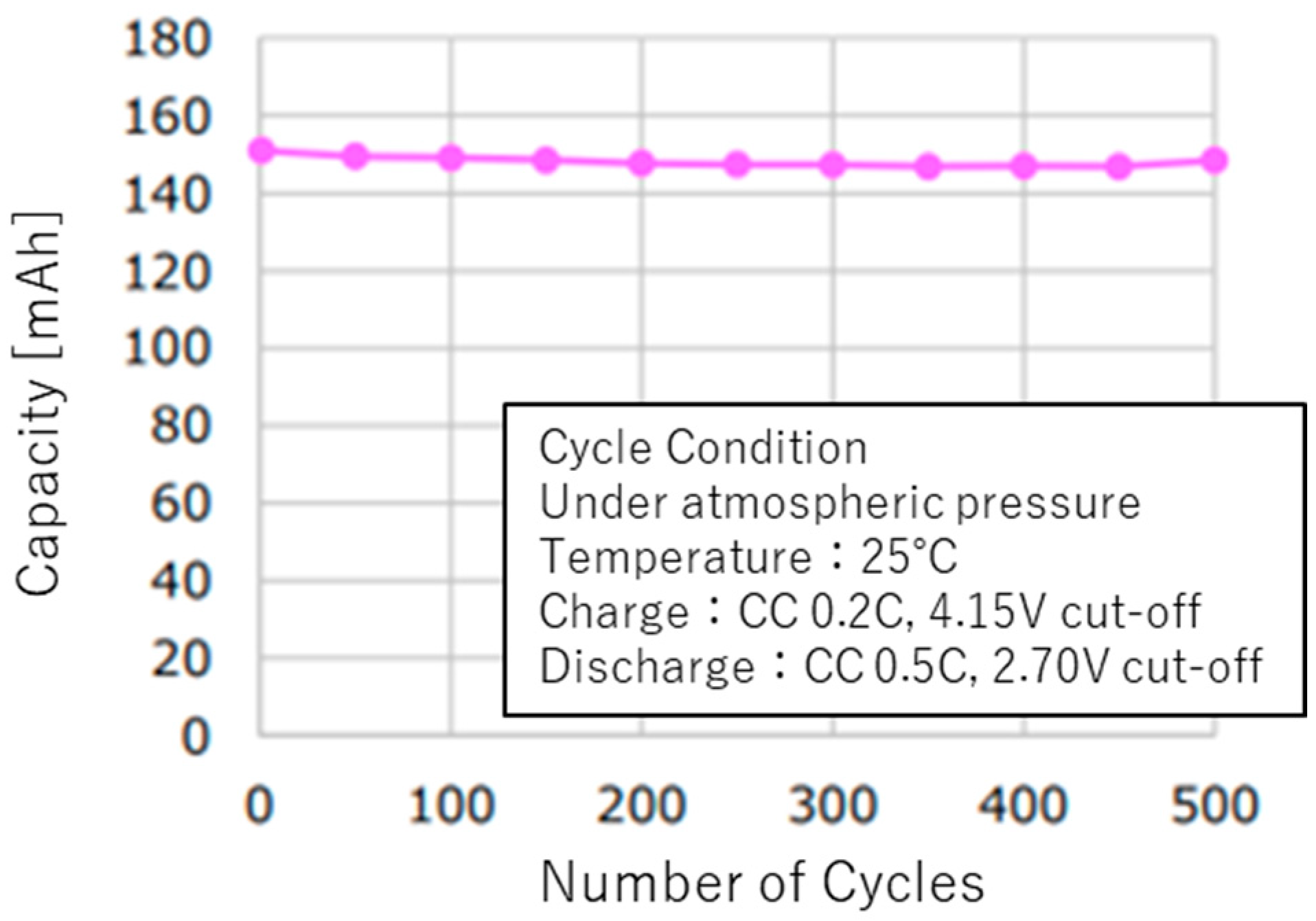
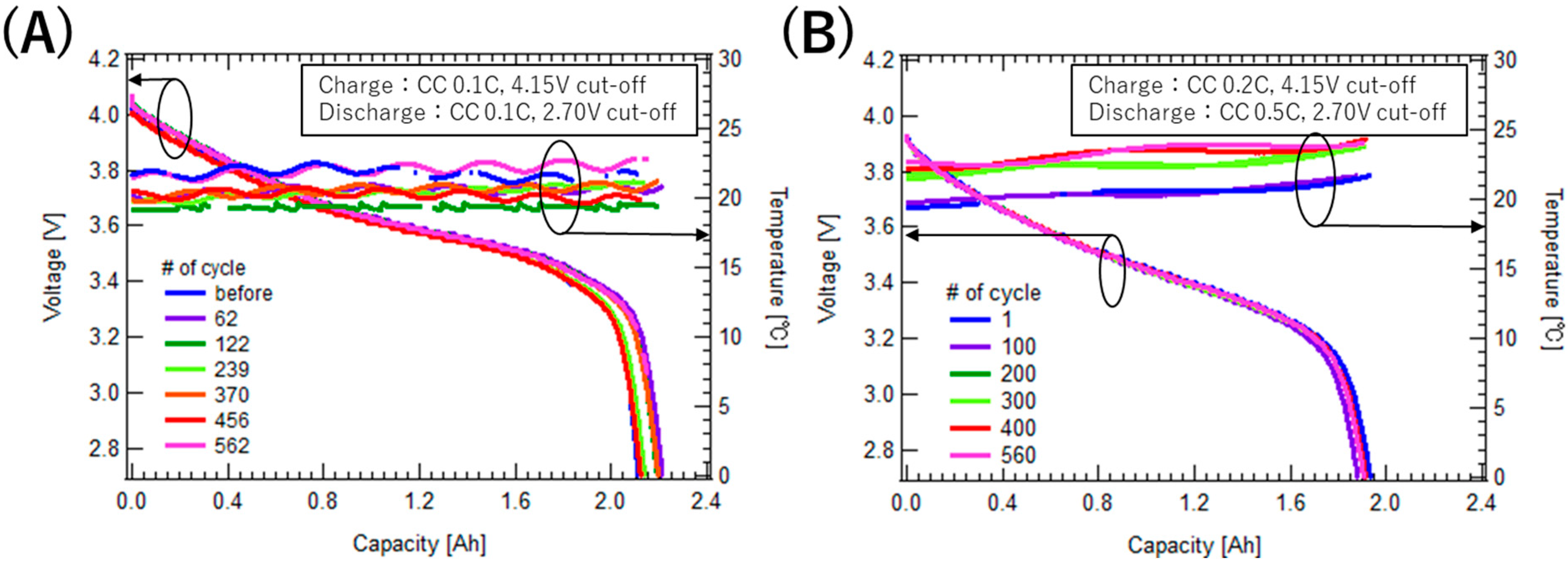
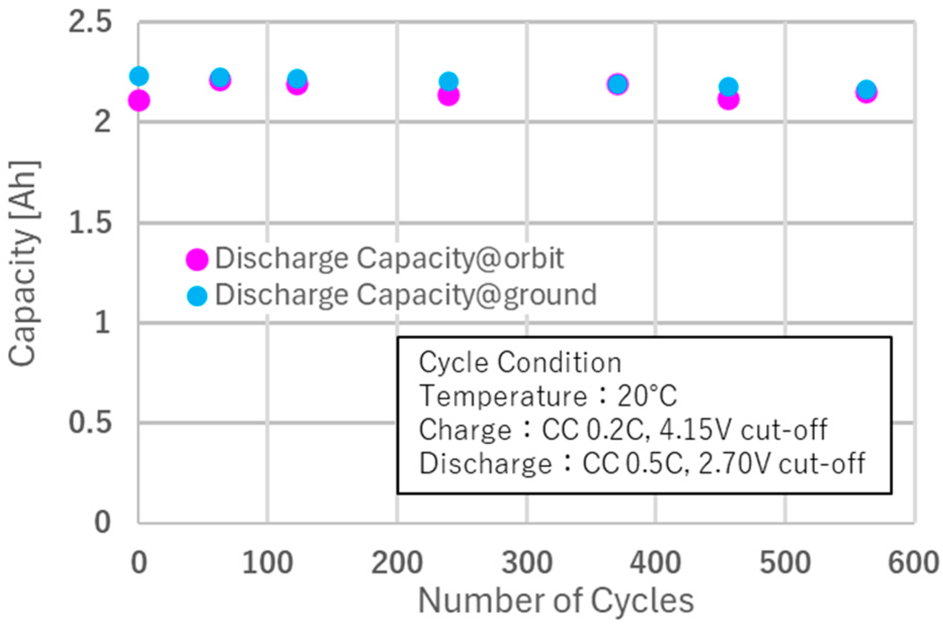
4.2. Continuous Charge–Discharge Cycle Characteristics

To evaluate the lifespan characteristics of the ASSB battery, charge–discharge cycle tests were conducted at a battery temperature of 20 °C, using 0.2 C CC charging and 0.5 C CC discharging. During the cycle tests, charge–discharge characteristics were periodically measured under 0.1 C CC charging and discharging conditions to assess the transition in discharge capacity. Figure 13A depicts the transition of the 0.1 C discharge characteristics, while Figure 13B presents the transition of the 0.5 C discharge characteristics during the continuous charge–discharge cycle test. Figure 14 shows the transition of the 0.1 C discharge capacity, comparing data from the space-demonstrated battery with data obtained using a single cell from the same production lot stored on the ground. Ground-based data were acquired under the same conditions as those in the on-orbit tests, with the discharge capacity multiplied by a factor of 15 to account for the parallel configuration of the space-demonstrated battery.
During the space demonstration, the battery temperature was maintained at approximately 20 °C using a heater. However, as no cooling mechanism was implemented, the battery temperature fluctuated between 19 °C and 23 °C, influenced by the surrounding thermal environment of the Space AS-LiB. While variations in discharge characteristics were observed owing to differences in temperature conditions, capacity fading remained negligible, with only an approximately 2% reduction in discharge capacity at the 562nd cycle compared with the 62nd cycle. This indicates that no significant capacity degradation occurred during the demonstration. In the operational simulation test conducted on the ground, where the battery cell temperature was controlled using an isothermal chamber, the capacity fading after 563 cycles was approximately 3% (Figure 14), which closely matched the capacity degradation observed in orbit. Additionally, as shown in Figure 13B, no anomalies were observed in the 0.5 C discharge curves throughout the cycles.
The radiation dose received during the on-orbit demonstration on the ISS was estimated to be less than 33 rad [19], which is significantly lower than the gamma-ray irradiation dose used in the standalone tests described in Section 2.2.6. Therefore, it can be reasonably concluded that the radiation effects on the ASSBs during the space demonstration were insignificant.
These results confirm that even after more than 500 cycles of 0.2 C charging and 0.5 C discharging in the space environment, the charge–discharge performance of the ASSB remained stable and exhibited no abnormalities.

5. Conclusions

This study presents the results of a demonstration of ASSBs, developed for space exploration and tested in the exposed environment of the ISS. The on-orbit evaluation of basic charge–discharge characteristics and continuous cycling performance confirmed that the ASSBs exhibit excellent charge–discharge and lifetime performance in space, comparable to their performance on the ground. Furthermore, the results demonstrate that on-orbit operational conditions can be reliably estimated using ground test data, as observed with conventional space batteries. These findings strongly support the potential application of ASSBs in spacecraft. For a deeper understanding of the behavior of ASSBs under space conditions, future studies incorporating analyses such as XPS and SEM are necessary.
The Artemis Project, which aims to establish sustainable human activities on the Moon, was proposed with Japan as one of the first eight nations to participate in 2020 [20]. Further advancements in lunar exploration are anticipated. ASSBs, with their wide operational temperature range, are expected to serve as vital energy sources for lunar exploration. The results of this study provide valuable insights and contribute to the full-scale application of ASSBs in future space exploration missions.

Author Contributions

Resources, S.N., H.O. and T.O.; data curation, Y.M., T.S., T.F., S.S., S.N., H.O., T.O. and H.N.; writing—original draft preparation, Y.M.; writing—review and editing, T.S., T.F., S.S., S.N., H.O., T.H., O.K. and H.N.; supervision, H.N.; project administration, T.F.; funding acquisition, T.H. and O.K. All authors have read and agreed to the published version of the manuscript.

Funding

This work was supported by the Space Exploration Innovation Hub Center (TansaX) and Japan Aerospace Exploration Agency (JAXA) through the RFP Collaboration Project.

Data Availability Statement

The data presented in this study are available in the article.

Acknowledgments

The authors express their gratitude to Mari Enomoto and the Human Spaceflight Technology Directorate of JAXA for their support of the space demonstration conducted on the ISS.

Conflicts of Interest

Authors Sousuke Nishiura, Hidetake Okamoto, Tetsuya Okawa were employed by the company Kanadevia Corporation. The remaining authors declare that the research was conducted in the absence of any commercial or financial relationships that could be construed as a potential conflict of interest.

References

  1. Creech, S.; Guidi, J.; Elburn, D. Artemis: An overview of NASA’s activities to return humans to the MOON. In Proceedings of the 2022 IEEE Aerospace Conference, Big Sky, MT, USA, 5–12 March 2022. [Google Scholar]
  2. NASA. Moon to Mars Architecture. Available online: https://www.nasa.gov/moontomarsarchitecture/ (accessed on 3 March 2025).
  3. Pathak, A.D.; Saha, A.; Bharti, V.K.; Gaikwad, M.M.; Sharma, C.S. A review on battery technology for space application. J. Energy Storage 2023, 61, 106792. [Google Scholar] [CrossRef]
  4. Williams, J.P.; Paige, D.A.; Greenhagen, B.T.; Sefton-Nash, E. The global surface temperatures of the Moon as measured by the Diviner Lunar Radiometer Experiment. Icarus 2017, 283, 300–325. [Google Scholar] [CrossRef]
  5. Chatain, A.; Spiga, A.; Banfield, D.; Forget, F.; Murdoch, N. Seasonal Variability of the Daytime and Nighttime Atmospheric Turbulence Experienced by InSight on Mars. Geophys. Res. Lett. 2021, 48, e2021GL095453. [Google Scholar] [CrossRef]
  6. Na, D.; Kampara, R.K.; Yu, D.; Yoon, B.; Martin, S.W.; Seo, I. Li1.4Al0.4Ti1.6(PO4)3 inorganic solid electrolyte for all-solid-state Li–CO2 batteries with MWCNT and Ru nanoparticle catalysts. Mater. Today Energy 2023, 38, 101418. [Google Scholar] [CrossRef]
  7. Zhu, Q.-C.; Ma, J.; Huang, J.-H.; Mao, D.-Y.; Wang, K.-X. Realizing long-cycling solid-state Li–CO2 batteries using Zn-doped LATP ceramic electrolytes. Chem. Eng. J. 2024, 482, 148977. [Google Scholar] [CrossRef]
  8. Zhang, Z.; Han, W.Q. From Liquid to Solid-State Lithium Metal Batteries: Fundamental Issues and Recent Developments. Nano-Micro Lett. 2024, 16, 24. [Google Scholar] [CrossRef] [PubMed]
  9. Machín, A.; Morant, C.; Márquez, F. Advancements and Challenges in Solid-State Battery Technology: An In-Depth Review of Solid Electrolytes and Anode Innovations. Batteries 2024, 10, 29. [Google Scholar] [CrossRef]
  10. Toyota, H.; Miyazawa, Y.; Kanaya, S.; Kukita, A.; Kondo, H.; Koide, K.; Kuhara, T.; Nakamura, K.; Kawano, T.; Naito, H.; et al. Development of Lithium-ion Pouch Cell Using Stainless Steel Laminated Film for JAXA’s Lunar Lander SLIM. Trans. Jpn. Soc. Aero. Space Sci. 2023, 66, 199–208. [Google Scholar] [CrossRef]
  11. Reddy, M.V.; Julien, C.M.; Mauger, A.; Zaghib, K. Sulfide and Oxide Inorganic Solid Electrolytes for All-Solid-State Li Batteries: A Review. Nanomaterials 2020, 10, 1606. [Google Scholar] [CrossRef] [PubMed]
  12. Naito, H.; Shimada, T.; Shimada, S.; Yamada, C.; Hoshino, T. Assessment of All Solid State Battery for Spacecraft. Ceramics 2019, 54, 316–320. [Google Scholar]
  13. Kanadevia. All-Solid-State Lithium-Ion Batteries. Available online: https://www.kanadevia.com/english/business/field/functional/as-lib.html (accessed on 3 March 2025).
  14. Shulman, H.; Ginell, S.W. Nuclear and Space Radiation Effects on materials. NASA SP-8053 1970. Available online: https://ntrs.nasa.gov/citations/19710015558 (accessed on 3 March 2025).
  15. Leita, G.; Bozzini, B. Impact of space radiation on lithium-ion batteries: A review from a radiation electrochemistry perspective. J. Energy Storage 2024, 100, 113406. [Google Scholar] [CrossRef]
  16. Tan, C.; Lyons, D.J.; Pan, K.; Leung, K.Y.; Chuirazzi, W.C.; Canova, M.; Co, A.C.; Cao, L.R. Radiation effects on the electrode and electrolyte of a lithium-ion battery. J. Power Sources 2016, 318, 242–250. [Google Scholar] [CrossRef]
  17. Nikicio, A.N.; Loke, W.-T.; Kamdar, H.; Goh, C.-H. Radiation Analysis and Mitigation Framework for LEO Small Satellites. In Proceedings of the 2017 IEEE International Conference on Communication, Networks and Satellite, Semarang, Indonesia, 5–7 October 2017. [Google Scholar]
  18. Mazur, J.E.; Zeitlin, C.; Schwadron, N.; Looper, M.D.; Townsend, L.W.; Blake, J.B.; Spence, H. Update on Radiation Dose From Galacticand Solar Protons at the Moon Usingthe LRO/CRaTER Microdosimeter. Space Weather. 2015, 13, 363–364. [Google Scholar] [CrossRef]
  19. Kodaira, S.; Naito, M.; Uchihori, Y.; Hashimoto, H.; Yano, H.; Yamagishi, A. Space Radiation Dosimetry at the Exposure Facility of the International Space Station for the Tanpopo Mission. Astrobiology 2021, 21, 1473–1478. [Google Scholar] [CrossRef] [PubMed]
  20. Eight Nations Sign Artemis According on Space Exploration. Available online: https://www.mext.go.jp/en/news/topics/detail/mext_00032.html (accessed on 3 March 2025).
Figure 1. Appearance of an ASSB used in the space demonstration. The Japanese text in the photo reads “All-solid-state battery”.
Aerospace 12 00514 g001
Figure 2. (A) Temperature dependence of the discharge performance. (B) Rate dependence of the discharge current.
Aerospace 12 00514 g002
Figure 3. Capacity retention during continuous charge–discharge cycles at 25 °C.
Aerospace 12 00514 g003
Figure 4. Discharge characteristics before and after the vibration tests.
Aerospace 12 00514 g004
Figure 5. (A) Change in the discharge curves during the 120 °C storage test. (B) Transition of the discharge capacity during the 120 °C storage test.
Aerospace 12 00514 g005
Figure 6. Capacity retention rate during continuous charge–discharge cycles at 120 °C under vacuum [13].
Aerospace 12 00514 g006
Figure 7. Discharge characteristics before and after the low-temperature storage test.
Aerospace 12 00514 g007
Figure 8. Transition of discharge characteristics in the lunar operation simulation test.
Aerospace 12 00514 g008
Figure 9. Discharge characteristics before and after 8 Mrad gamma-ray irradiation test.
Aerospace 12 00514 g009
Figure 11. Image of the Space AS-LiB installed on SPySE. The item shown inside the red box is the Space AS-LiB.
Aerospace 12 00514 g011
Figure 12. Discharge characteristics of the ASSB battery in orbit (A): 0.1 C CC charging, 0.1 C CC discharging; (B): 0.2 C CC charging, 0.5 C CC discharging; and (C): 0.2 C CC charging, 1.0 C CC discharging.
Aerospace 12 00514 g012
Figure 13. Evolution of discharge curves in the continuous charge–discharge cycle test: (A) 0.1 C CC charging and 0.1 C CC discharging for capacity verification, and (B) 0.2 C CC charging and 0.5 C CC discharging during continuous charge–discharge cycles. The arrows extending from each curve indicate the corresponding axis.
Aerospace 12 00514 g013
Figure 14. Comparison of discharge capacity variation in continuous charge–discharge cycle characteristics: on-orbit data vs. ground simulation testing.
Aerospace 12 00514 g014
Table 1. Specifications of ASSBs for space demonstration.
PropertySpecification
Cathode Active MaterialsNCM (nickel–cobalt–manganese)
Anode Active MaterialGraphite-based
Solid ElectrolyteSulfide type (Li6PS5X)
Dimensions5 mm × 65.5 mm × 2.7 mm
Weight25 g
Voltage Range2.70–4.15 V
Nominal Voltage3.65 V
Capacity140 mAh
MAX Charge–Discharge Rate
(Recommended)
Charge: 0.1 C
Discharge: max. 1.0 C
Operation Temperature Range
(Recommended)
Charge: +20~+120 °C
Discharge: −40~+120 °C
Table 2. Sinusoidal and random vibration test conditions.
FrequencyLevel
Sinusoidal
vibration test
5–27.9 HzMaximum amplitude:
6.4 mm
27.9–100 Hz196 m/s2
Random
vibration test
20–58 Hz+6 dB/oct.
58–700 Hz48.02 m2/s3
700–2000 Hz−6 dB/oct.
23.63 g
Table 3. Operating conditions of ASSBs in orbit.
TempCharge
Rate
Cut-Off
Voltage
Discharge RateCut-Off
Voltage
Charge–discharge characteristics20 °C,
23 °C,
40 °C
0.1 C,
0.2 C
4.15 V0.1 C,
0.5 C,
1 C
2.70 V
Continuous
cycle
characteristics
20 °C0.2 C4.15 V0.5 C2.70 V
Disclaimer/Publisher’s Note: The statements, opinions and data contained in all publications are solely those of the individual author(s) and contributor(s) and not of MDPI and/or the editor(s). MDPI and/or the editor(s) disclaim responsibility for any injury to people or property resulting from any ideas, methods, instructions or products referred to in the content.

