1. Introduction
As the performance of aircraft and aero-engines continues to improve, it is becoming increasingly challenging for single disciplines, such as aerodynamic design optimization (ADO), to meet design requirements. In most cases, practical design can only be achieved with considerable aero-structural trade-offs [
1]. Due to the rapid increase in computing capability and advanced numerical methods, optimization based on numerical simulation has become more and more sophisticated in aerospace design. In addition to the design of airfoils, wings, and so on [
2,
3], the design optimization of rotor blades in aero-engines is also essentially a multidisciplinary and multi-objective process [
4,
5]. In design optimizations with large-scale geometric variations such as the blade sweep, the lean and stacking lines are changed significantly, as are the static structural stresses of the blade. In such situations, the structural performance must be considered when improving the aerodynamic performance to achieve multi-disciplinary design optimization (MDO).
Among the large-scale design parameters, studies on the impact of blade sweep are crucial. In 1991, Rabe et al. [
6] experimentally investigated the impact of blade sweep on the performance changes in a low aspect ratio fan. They found that the adiabatic efficiency can be increased by weakening the shock wave on some specific spans. In the meantime, Yamaguchi et al. [
7] found that forward sweep is helpful for varying the pressure gradient on the blade and, thus, is effective for decreasing the secondary flow loss. Subsequently, many studies based on both experiments and numerical simulations have been reported, demonstrating the impact mechanisms of blade sweep on the evolution of flow structure and variations in aerodynamic performance and even in sound power level [
8,
9,
10,
11,
12,
13,
14]. In 2002, Denton et al. [
11] studied the effects of blade sweep on a transonic fan; the transonic fan had an efficiency close to 93.0% in design operation conditions and the authors observed very little change in efficiency. Meanwhile, they pointed out that high structural stress requires consideration in blade sweep design.
In addition to aerodynamic studies, blade sweep—regarded as a design technique—has also been adopted in aerodynamic optimization. Lian et al. [
15] achieved multi-objective aerodynamic optimization by applying blade sweeping to a transonic fan rotor, NASA Rotor 67, in which the adiabatic efficiency and total pressure ratio were regarded as the multiple objectives. Samad et al. [
16] developed a multiple-surrogate modeling approach to deal with the blade sweep, lean, and skew design variables. Vad János [
17] reviewed the forward blade sweep technology applied to low-axial fan rotors, proving this method to be effective in controlling the flow loss. Okui et al. [
18] constructed a differential evolutionary algorithm in combination with an artificial neural network for the three-dimensional optimization of blade sweep. Luo et al. [
19] carried out ADO via blade sweep in a transonic compressor rotor, NASA Rotor 37, significantly increasing the adiabatic efficiency. Generally, blade sweep design optimization research focuses on the improvement of aerodynamic performance; meanwhile, studies on aero-structural MDO are rare [
4,
5]. However, swept blades quite probably have rather different structural performances than the original blades, as their large-scale design parameters have been changed.
As reviewed by Li and Zheng [
20] with regard to the design optimization of turbomachinery, the response surface method (RSM) [
21,
22] is a commonly used optimization tool due to its versatility and easy implementation. On one hand, it takes little effort for the RSM to combine optimization objectives from different disciplines. On the other hand, computational resource demands when constructing the response surface are no longer a major problem, due to advances in computing capability. In a previous study [
19], different surrogate model (SM) methods have been introduced. For most SMs, the kernel functions are empirically specified. These SM methods lack generality in different response problems. However, proper orthogonal decomposition (POD)-based SM methods were contrastively recommended in ADO for the following reasons. (1) The kernel functions in POD-based SMs are determined by singular value decomposition (SVD) on the snapshots (training samples), meaning that the kernel functions can be synchronously updated along with the snapshots. In such cases, the generality of POD-based SM methods can be improved. (2) Adaptive sampling techniques can be used for the training of POD-based models. The computational cost for model training can be significantly reduced using as few training samples as possible. If the POD snapshots consist of both aerodynamic and structural performance parameters, the kernel functions should include all the aero-structural information. In theory, the POD-based SM methods can also be applied to MDO. However, there is notable scarcity of research in this area. In this study, a POD-based hybrid SM method for MDO is introduced and then applied to a series of aero-structural optimizations to demonstrate the effects of blade sweeping in terms of improvements in aerodynamic and structural performance.
In the present study, an optimization framework and the implementation of MDO are first introduced. In the design optimization of a low-aspect-ratio transonic fan rotor, NASA Rotor 67, aerodynamic and structural performance are considered equally important, with blade sweep used to balance both objectives. The POD-based hybrid model, assisted by a radial basis function (RBF) and an adaptive sampling technique, is trained to respond to both the aerodynamic and structural parameters in the design space. One ADO and a series of different MDOs are carried out. The objective function is a combination of two parameters among the adiabatic efficiency, total pressure ratio, and structural stress. The optimization results are given in detail and compared to demonstrate the impacts of blade sweep on aerodynamic and structural performance.
2. Optimization Framework
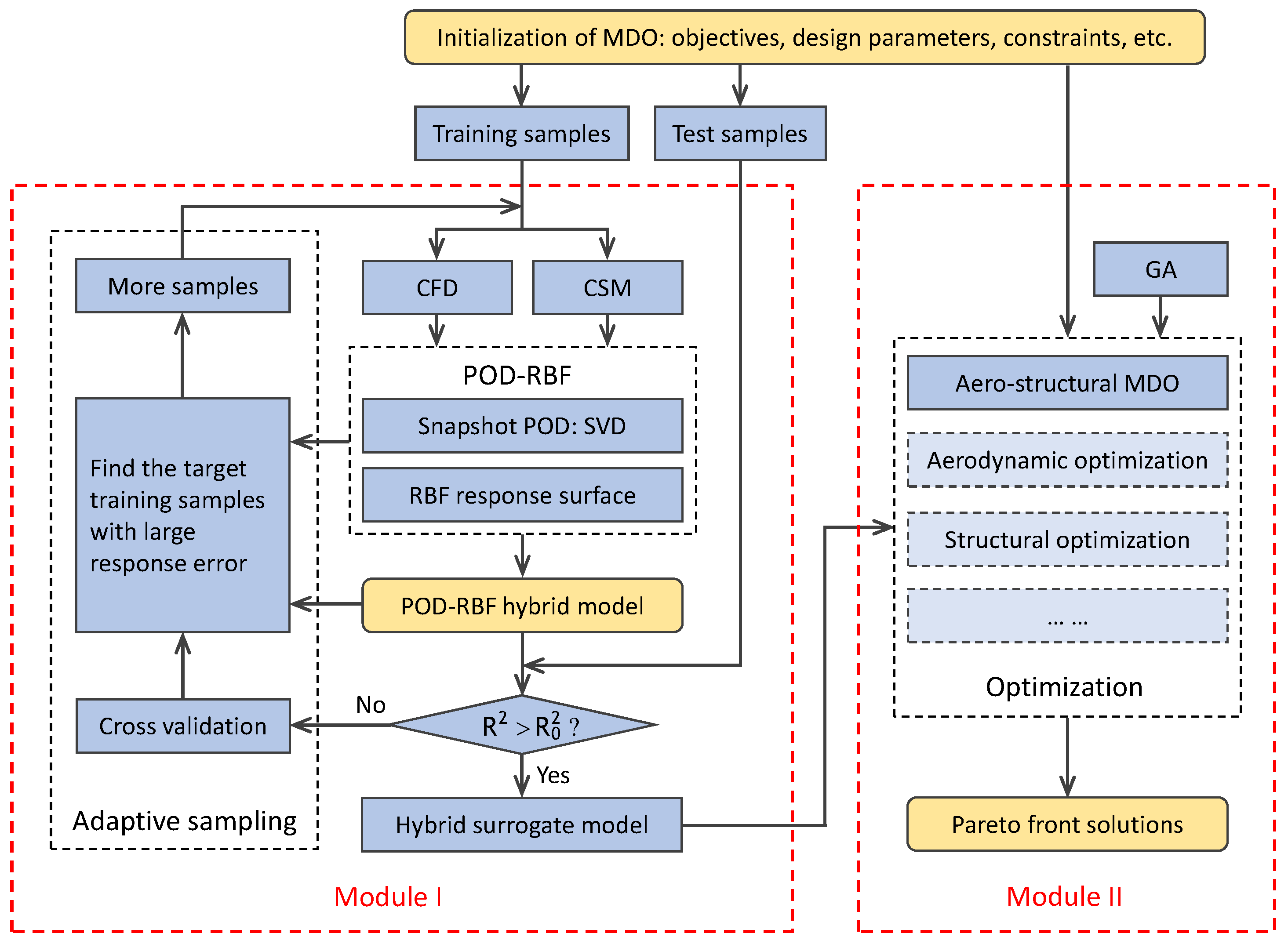
The present MDO is achieved using an in-house optimization framework including computational fluid dynamics (CFD), computational structural mechanics (CSM), parameterizations of turbomachinery blades, the genetic algorithm, and so on. A POD-based hybrid model with sufficient response accuracy is trained, from which the aerodynamic and structural performance parameters are measured and used as performance predictions in design optimization. The optimization framework is illustrated in
Figure 1. There are two modules in the framework, model training (Module I) and design optimization (Module II). Design optimization using the framework can be accomplished through the following steps.
Step 1. Determine the optimization objectives, constraints, design parameters, and corresponding parameterizations, among other necessary values. A group of training samples and a group of test samples are produced by Latin hypercube sampling (LHS). The averaged correlation coefficient
and averaged maximum Euclidean distance
of the training samples are regarded as the multiple objectives for producing the training samples.
where
w is the weight. Using a simple searching method, a group of training samples with minimum
and minimum
can be determined from a large number of sample groups. The minimum
means there is the maximum averaged independency, while the minimum
is associated with maximum space filling.
Step 2. After obtaining the aerodynamic and structural performance parameters using CFD and CSM, respectively, the performance and geometric parameters of all the training samples are stored in a matrix. Then, the eigenvalues, eigenvectors, and basis modes can be determined via Snapshot POD. Meanwhile, from the geometric parameters and the eigenvectors, a series of response surfaces can be constructed using the responding coefficients of basis modes. The details of the POD-based hybrid model are introduced in
Section 3.
Step 3. Evaluate the response accuracy of the POD-based hybrid model using the test samples. If the response accuracy is sufficient, the hybrid model can be used for design optimization. If the hybrid model lacks sufficient response accuracy, more training samples are necessary to train the hybrid model.
Step 4. To produce additional samples via adaptive sampling, the cross-validation method is employed to evaluate the response error of the hybrid model on each existing training sample. The target sample with the largest response error can be found. In the subspace surrounding the target sample, a series of additional samples are produced via LHS and added into the original training samples. Then, Step 2 and Step 3 are repeated until the response error of the hybrid model falls within tolerance.
Step 5. With the assistance of the POD-based hybrid model and genetic algorithm, the global optimums can be found. If the hybrid model is trained by either taking only the aerodynamic parameters or both the aerodynamic and structural parameters into account, the optimization framework can be used for ADO and aero-structural MDO, respectively.
2.1. Computational Fluid Dynamics Analysis
NASA Rotor 67 is an axial-flow transonic fan rotor with a design tip relative Mach number of 1.38 at the leading edge (LE). The rotor has 22 blades and an aspect ratio of 1.56. It was designed by the NASA Lewis Center and thoroughly experimentally studied by Strazisar et al. [
23]. The design rotation speed, total pressure ratio, and mass flow rate are 16,043 rpm (rotation per minute), 1.63, and 33.25 kg· s
−1, respectively. The height of tip clearance is about 1.0 mm (millimeters). Due to the rich experimental data for this transonic fan, it has been investigated in lots of aerodynamic design optimization studies [
16,
24,
25].
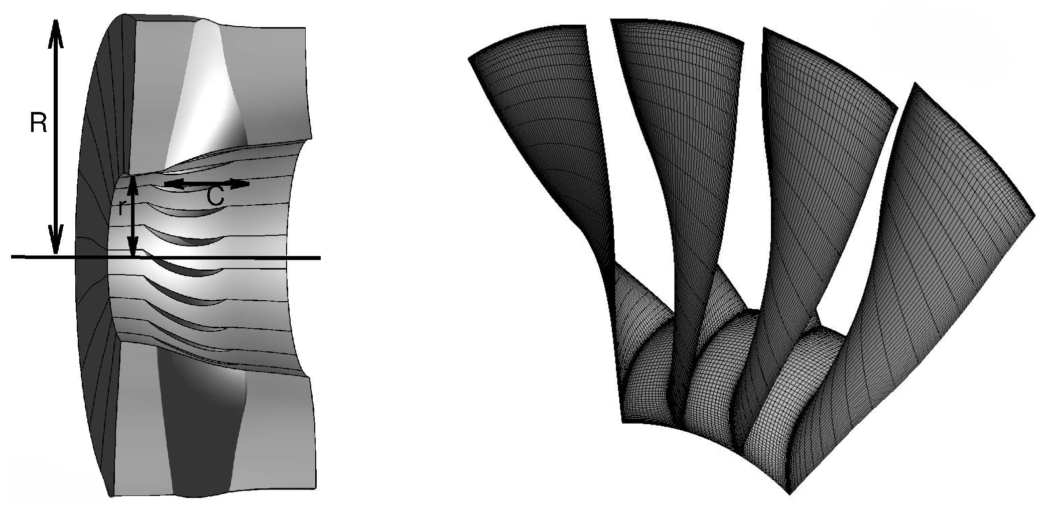
The configuration of Rotor 67 and the H-type grid used in the study are given in
Figure 2. An in-house flow solver is integrated in the framework to solve the three-dimensional Reynolds-averaged Navier–Stokes equations. The classical JST scheme and multi-grid technique are used to enable flow computation with high efficiency. The Spalart–Allmaras one-equation turbulence model [
26] is used to resolve the boundary flow. At the inlet of blade passage, the total pressure, total temperature, and inlet flow angle are specified as 101,325 Pa, 288.15 K, and 0 degrees, respectively, while at the outlet, the static pressure on the hub is specified and the radial equilibrium equation is solved to determine the spanwise pressure distribution. Non-slip boundary conditions are used on the blade and endwalls, and periodic boundary conditions are used on the circumferential boundaries.
Four grids with different resolutions are generated to obtain the grid-independent solutions. The calculated total pressure ratio
and adiabatic efficiency
are given in
Figure 3, where
N is the serial number of grids. The flow solutions of grid 3 and grid 4 are quite close, with 0.015% and 0.005% relative errors in adiabatic efficiency and total pressure ratio, respectively. The third grid, with about 0.76 million grid points for each blade passage, is used in the following experiments. The predicted choke mass flow rate is 34.99 kg· s
−1, while the experimental value is 34.96 kg· s
−1.
Figure 4 shows the operation characteristics of total pressure ratio and adiabatic efficiency versus relative mass flow, which is inherently the normalized mass flow rate using choked mass flow as a reference. The comparisons between CFD solutions and experiment data demonstrate that the overall aerodynamic performance parameters can be obtained with sufficient accuracy.
In the following optimization study, the rotor is operating at near peak efficiency. The normalized mass flow rate, the calculated adiabatic efficiency, and total pressure ratio are about 99%, 92.74%, and 1.628, respectively.
2.2. Computational Structural Mechanics Analysis
The structural performance parameters, including displacement, strain, and von Mises stress, among others, are calculated by solving the static structural equation using finite element analysis.
where
is the stiffness matrix,
is the force vector including aerodynamic load and centrifugal force, and
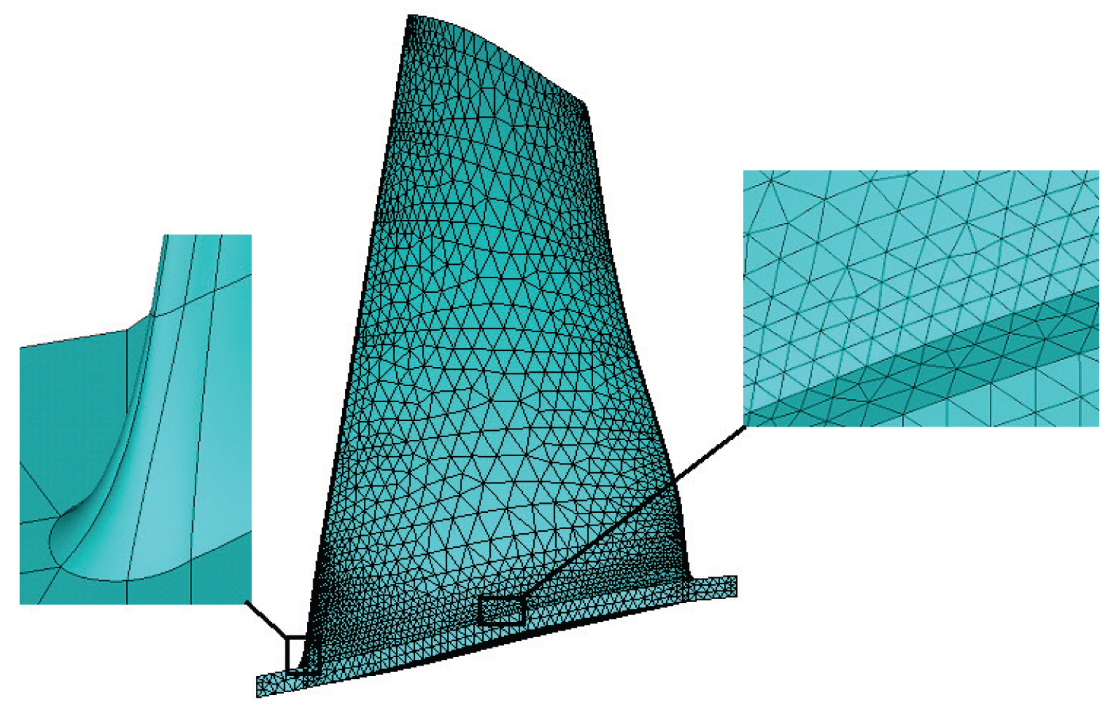
is the displacement vector. Ten-node tetrahedral elements are adopted in mesh generation. As illustrated in
Figure 5, the blade hub fillet radius is about 2%–3% of the blade height. In the structural simulation, the hub is regarded as the fixed constraint. On the blade, the centrifugal force due to high-speed rotation and the static pressure load due to gas flow are imposed. To transfer the pressure load and blade displacement between the fluid field and structural field on the fluid–structure interface (blade surface), a simple radial basis function-based interpolation method developed by the present authors [
27] is applied. It should be emphasized that fluid–structure interaction is not considered in the present study since the negative impact of blade deformation on performance can be ignored relative to the significant gains through optimization.
In the present study, flow and structural simulations involving Rotor 67 are carried out under conditions where the rotor is operating near peak efficiency; the accuracy of load and deformation transfer on the fluid–structure interface under these conditions has already been validated in previous work [
27]. After imposing the aerodynamic load on the blade, structural simulation can be performed. The mechanical properties of the blade material (Titanium) are given in
Table 1, where
,
,
, and
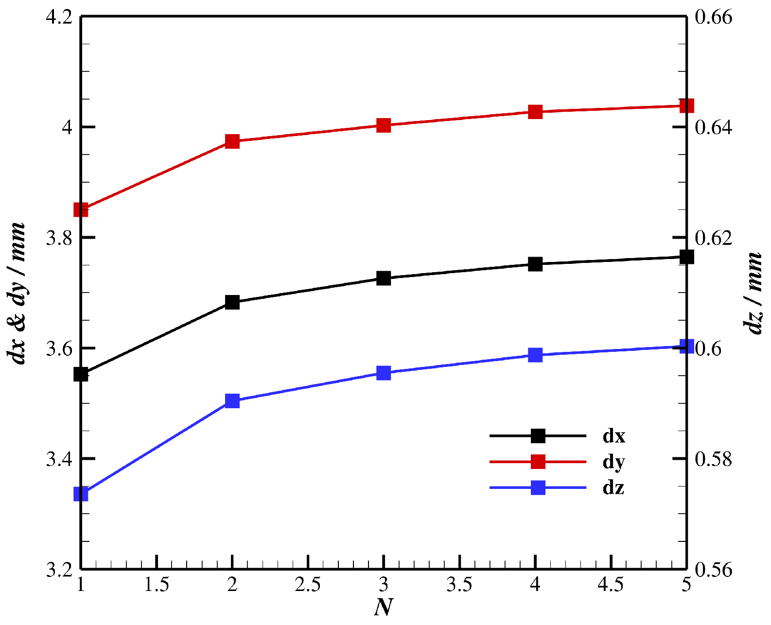
indicate the density, Young’s modules, Poisson ratio, and yield strength of Titanium, respectively. Similar to flow simulation, grid-independent investigation is carried out on five different grids. The structural solutions are given in
Figure 6, where
,
, and
are the displacements of the leading edge at the blade tip in the axial, pitchwise, and spanwise directions, respectively. It is found that the solutions for grid 4 are similar to those of grid 5 and so will be used in the following. The converged solution of von Mises stress is also given in the table, where
and
are the maximum von Mises stresses with only the centrifugal force and both the centrifugal force and static pressure load taken into account, respectively. It should be noted that the result of
is close to that reported by Lian and Liou [
4]. The stress resulting from the aerodynamic load is about 10% of the total stress.
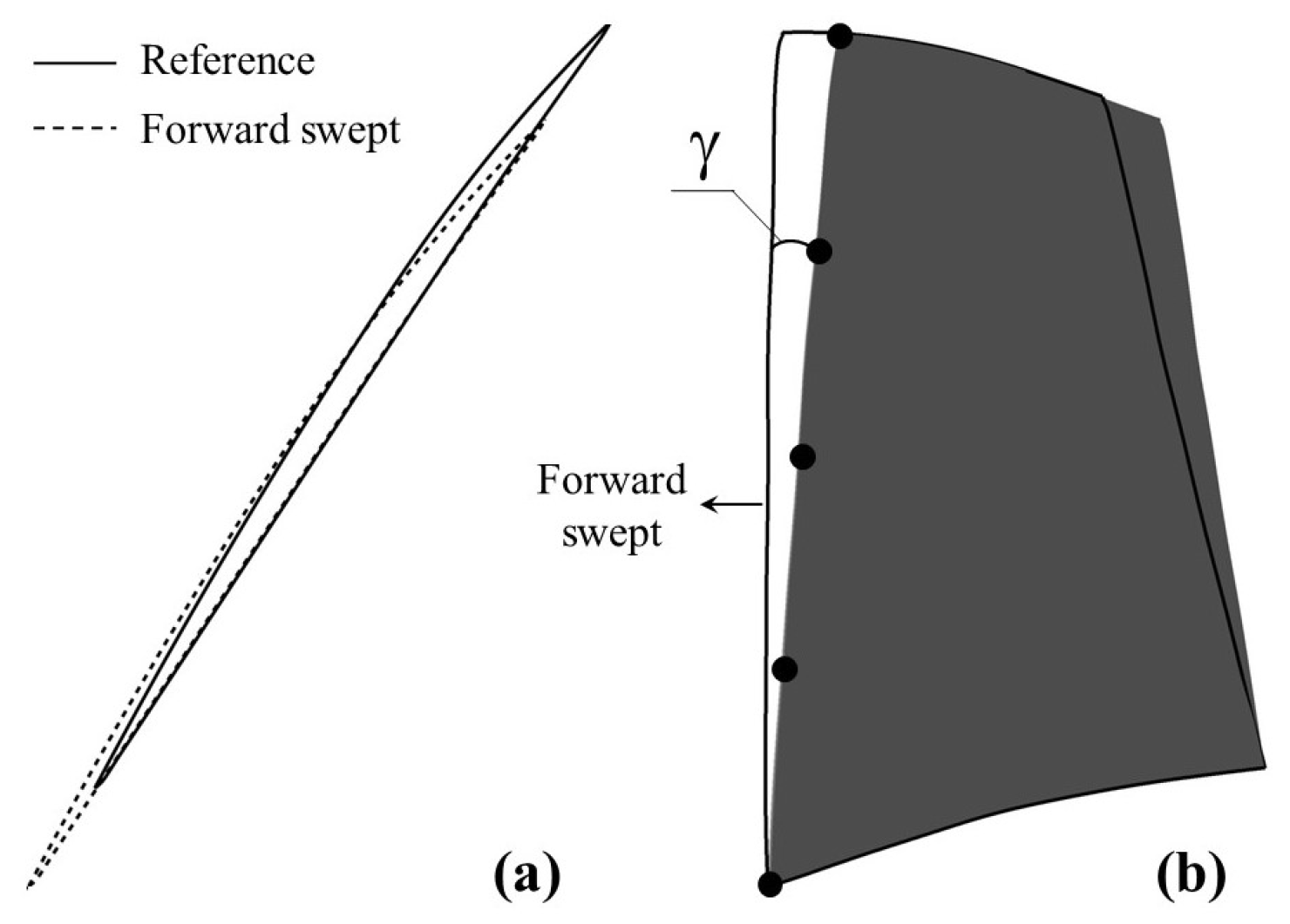
2.3. Parameterizations of Blade Sweep
The general definition of forward and backward sweep is that the blade profile moves correspondingly upstream and downstream along the local chord line [
16].
Figure 7 is a schematic drawing of blade sweep that was published in previous work [
19]. With such a parameterization method for blade sweep, the blade profiles are shifted, as a whole, along their local chord line, resulting in a sweep angle
, as shown in the figure.
Four Gaussian RBFs are used as the perturbation bumps placed on the LE:
where
represents the design variables controlling the geometric perturbations of the sweep angle,
represents the spanwise locations of the centers of bumps,
controls the decaying rates of the perturbation bumps, and
N is the number of bump functions. To quantify the influence of perturbation bumps, the half-decaying radius
is defined.
where
determines the range of influence of each bump and is 0.4 times the blade height for both bumps.
To fix the blade hub, the final perturbation along the span is calculated as the sum of
times the function
, which linearly decays to zero from blade tip to blade hub.
where
H is the blade height at LE. The function
linearly depends on
r being zero and
H at the blade hub (
) and blade tip (
), respectively.
There are several advantages of using the Gaussian RBF as the perturbation bump. Firstly, the perturbation center can be determined according to the flow characteristics. Secondly, the amplitude and range of the perturbation are easily adjusted. Moreover, the sweep design obtained using this parametrization method is sufficiently smooth.
2.4. Stress Analysis of Swept Blades
It is well known that the maximum stress
, as shown in
Table 1, is responsible for the failure of a rotor blade. However, sometimes the average stress is also used in aero-structural optimization [
28]. In such cases, it should be investigated whether the variations in maximum stress and average stress are consistent. Thus, the effects of the employed blade sweep parameterization method on stress variations are investigated in this study.
Besides the original rotor blade, six swept blades are generated in the design space, and the configurations are given in
Figure 8. Some of the blades are totally forward swept, some are backward swept, and others are compound swept. With the introduced CSM method, the distribution of stress is calculated for each blade. The average
and maximum
stresses are given in
Table 2. In comparison with the original blade, it is clear that for the swept blades with reduced average stress, the maximum stress also decreases, and vice versa. Moreover, the maximum stress of all the blades appears in the regime surrounding the intersection point between the blade leading edge and hub. This is reasonable because the curvature of this point is maximized and the von Mises stress on the hub resulting from centrifugal force is large. These results demonstrate that, in using the present parameterization method of blade sweeping, the optimization for reducing the average stress is acceptable, which is also useful for reducing the maximum stress.
4. Results and Discussion
Before optimization, hybrid model training is required. Following the same procedures shown in
Section 3 but with four design parameters, additional samples are adaptively produced starting from 20 initial training samples. Each sample (i.e., POD snapshot) consists of design parameters and performance parameters, including the total pressure ratio
, adiabatic efficiency
, mass flow rate
, and average von Mises stress
.
Figure 11 presents the convergence history of the average response error versus the sample number. The average response error is defined by
where
is the
i-th snapshot, and the subscripts
and
represent the performance parameters obtained using the POD-RBF hybrid model and numerical simulations.
Finally, with 92 training samples,
reaches the target
, and the average response error is about 0.05%. Moreover, the average response error of each performance parameter is calculated and given in
Table 3. The maximum error is about 0.16% for the average stress, while the response errors of the other three aerodynamic performance parameters are all within 0.02%, demonstrating the sufficient response accuracy of the POD-based hybrid model. In the following, the model will be used for the optimization of Rotor 67.
4.1. Aerodynamic Design Optimization
For the purpose of comparison, one multi-objective aerodynamic design optimization is also investigated. The cost function
I, given as
is used in ADO, increasing the adiabatic efficiency
and total pressure ratio
while maintaining the mass flow rate
. In the above equation,
is the mass flow rate of the original rotor blade. Moreover,
is 0.2% (0.002) in this study.
In adjusting the weight
w in Equation (
15), a series of optimal solutions can be obtained.
Figure 12 gives the optimal solutions of both adiabatic efficiency and total pressure ratio. These two objectives compete in the design space. Among the three marked solutions, the maximum adiabatic efficiency can be obtained for Opt-I, while the maximum total pressure ratio can be obtained for Opt-II. Moderate improvements in
and
can be obtained for Opt-III. The variations in the performance parameters are given in
Table 4.
Figure 13 illustrates the aerodynamic shape of the original and the optimized blades of Opt-I, Opt-II, and Opt-III. The blades are forward swept on the whole span of Opt-II and Opt-III, which contributes to considerable increases in the total pressure ratio. Compared with Opt-II, the reduced amount of forward sweeping on the outer spans of Opt-III increases the adiabatic efficiency. The optimized blade of Opt-I is forward swept on the inner spans, backward swept on the outer spans, and forward swept on the ultra-outer spans very close to the blade tip, which results in an almost maintained total pressure ratio and increased adiabatic efficiency. More details regarding the variations in performance parameters and the impact mechanisms of blade sweeping have been introduced in previous work [
33].
In order to evaluate the practical application feasibility of the optimized rotor fan, it is necessary to calculate the variations in the structural performance of the optimized blades obtained via ADO. In the present study, the von Mises stresses are calculated.
Table 5 gives the maximum
and average
von Mises stresses of the original and optimized blades. It is clear that the von Mises stresses increase as the total pressure ratio increases. This is attributed to the varied aerodynamic loading and the redistribution of blade mass. These results demonstrate that if improved aerodynamic and structural performance are both required, it is necessary to carry out aero-structural multi-disciplinary design optimization.
4.2. Aero-Structural Optimization with Stress Constraint
Aero-structural multi-disciplinary design optimization is mainly performed by either taking the stress as a constraint or objective in the design optimization. Equation (
16) is the cost function for optimization, maximizing both the adiabatic efficiency
and total pressure ratio
with constrained average von Mises stress
, which is named MOBJ-I in the following.
where
is the von Mises stress of the original Rotor 67, and tolerances
and
are both 0.2% (0.002).
Figure 14 presents the Pareto solutions of the adiabatic efficiency and total pressure ratio. Although the adiabatic efficiencies of the optimized blades are significantly different, the total pressure ratio varies slightly. The variations in
and
are quite different to those in
Figure 12, where these two objectives are competitive. As shown by the results in
Table 4 and
Table 5, the variation in the total pressure ratio is dependent on the variation in von Mises stress. In the MOBJ-I optimization, since the stress is constrained in the optimization, the total pressure ratio of the Pareto solutions exhibit slight variations.
Figure 15 illustrates the blades of the optimal solutions Opt-IV, Opt-V, and Opt-VI, as shown in
Figure 14. In comparison with the original blade, the three optimized blades are forward swept on the inner and ultra-outer spans and backward swept on the outer spans. The blade sweep variations are quite similar to those of the optimized blade Opt-I. In other words, this kind of blade sweeping favors increasing the adiabatic efficiency and maintaining the total pressure ratio and mass flow rate.
The results of the current MOBJ-I and those of aerodynamic optimization demonstrate a feasible configuration of blade sweeping favoring an increase in adiabatic efficiency while maintaining the mass flow rate. For this kind of configuration, both the total pressure ratio and average von Mises stress slightly vary in the design space.
4.3. Aero-Structural Optimization Reducing Stress
In this section, the optimization takes reducing the average stress into account. Only the mass flow rate is constrained in aero-structural optimization MOBJ-II, which has the cost function
while both the mass flow rate and total pressure ratio are both constrained in aero-structural optimization MOBJ-III, which has the cost function
where tolerance
is 0.2% (0.002).
Figure 16 presents the Pareto solutions of MOBJ-II and MOBJ-III. It is clear that without the constraint of total pressure ratio (MOBJ-II), the average stress can be significantly reduced and the multiple objectives are competitive in the design space. With the constraint of the total pressure ratio, the decrease in average stress is substantially reduced through MOBJ-III.
Table 6 gives the relative variations in the aerodynamic and structural performance parameters of the Opt-VII, Opt-VIII, and Opt-IX optimized blades specified in
Figure 16b. Both the mass flow rate and total pressure ratio are strictly maintained, while the adiabatic efficiency of the optimized blades is increased. Although the reduction in average stress falls from the level observed for MOBJ-II, as shown in
Figure 16a, considerable gains regarding stress reduction are obtained.
As shown in
Figure 13 and
Table 5, the blade configuration with forward sweeps on the inner and ultra-outer spans and backward sweeps on outer spans favors the reduction in von Mises stress on the rotor blade. When using the aero-structural optimization MOBJ-III, all the three optimized blades (Opt-VII, Opt-VIII, and Opt-IX) have similar configurations, as shown in
Figure 17. Recall that the von Mises stress of the optimized blade (i.e., Opt-I) with a similar total pressure ratio to the original blade has about a 2.66% decrease, as shown in
Table 5. The optimization of MOBJ-III is in fact more like a fine optimization in a narrow design space neighboring Opt-I. For the three optimized blades shown in
Figure 16b, the total pressure ratio and the corresponding aerodynamic loadings are similar and the redistributions of blade mass due to different configurations of blade sweeping are responsible for the variations in centrifugal force and thus the von Mises stress.
In the following, the optimized blade Opt-VII is taken as an example for studying the effects of blade sweeping on aerodynamic performance.
Figure 18 illustrates the distributions of the isentropic relative Mach number on different spans of the original and optimized blades. On inner spans, such as on the 25% and 40% spans, blade sweeping slightly contributes to performance improvements. However, on the outer spans, where flow is transonic, blade sweeping significantly contributes to the movement and weakening of the shock wave, such as sweeps on the suction side of the 75% span and those on both the suction and pressure sides of the 95% span, which favor the decrease in flow loss and the increase in adiabatic efficiency.
Figure 19 presents the contours of isentropic relative Mach number on the suction and pressure sides of the original and optimized blades. The contours are more useful to illustrate the impacts of blade sweeping on the flow variations. Due to the backward sweeping of the optimized blade, the positions of shock waves on both sides move relatively upstream, which can also be clearly found in
Figure 18c. Moreover, for the original blade, the strong shock on the suction side changes to
-shaped shocks after optimization, a phenomenon known to be effective in reducing shock loss.
5. Conclusions
This study introduced an optimization framework based on CFD, CSM, and a surrogate model. The principles and implementation of an adaptive sampling-assisted POD-RBF hybrid model were introduced. The optimization framework was applied to both aerodynamic design optimization and aero-structural multi-disciplinary design optimization through the blade sweeping of a transonic fan rotor, NASA Rotor 67. The results from ADO and MDO, as well as those of different aero-structural optimizations, were compared. The main conclusions are as follows:
(1) The optimization results demonstrate that the POD-based hybrid surrogate model is suitable for practical use in MDO, due to its high efficiency in model training and high prediction accuracy. The introduced optimization framework can be applied to various types of optimization problems. Through comparative analysis of the optimization results, the effects of blade sweeping in terms of improvements in the total pressure ratio, adiabatic efficiency, and average stress are clearly demonstrated.
(2) As expected, aerodynamic optimization is useful for increasing the adiabatic efficiency and total pressure ratio of the transonic fan rotor. However, the von Mises stress of the optimized blades has different behavior. The maximum and average stresses increase for most Pareto solutions, which are scenarios unacceptable in blade design. It is necessary to perform aero-structural multi-disciplinary design optimization for product design.
(3) When using the present parameterization method for blade sweeping, the variations in the maximum stress and average stress of the rotor blade are consistent. Reducing the average stress simultaneously reduces the maximum stress. For the fan rotor, the average stress is dependent on aerodynamic loading. Without the constraint of the total pressure ratio, stress reduction and adiabatic efficiency increases can be obtained through aero-structural optimization. The results further demonstrate that optimized blades with forward sweeping on the inner and ultra-outer spans and backward sweeping on outer spans are beneficial for reducing the average stress.


