Article

Factors Influencing Step Ablation in the Expansion Section of a Composite Nozzle in a Solid Rocket Motor

1
National Key Laboratory of Solid Rocket Propulsion, Northwestern Polytechnical University, Xi’an 710072, China
2
Academy of Aerospace Solid Propulsion Technology, Xi’an 710025, China
*
Author to whom correspondence should be addressed.
Aerospace 2025, 12(6), 499; https://doi.org/10.3390/aerospace12060499 (registering DOI)
Submission received: 22 April 2025 / Revised: 21 May 2025 / Accepted: 27 May 2025 / Published: 31 May 2025

Abstract

:
During the operation of a solid rocket motor, the nozzle, which is a key component, is subjected to extreme conditions, including high temperatures, high-speed gas flow, and discrete-phase particles. For composite nozzles incorporating a carbon/carbon (C/C) throat liner and a carbon/phenolic expansion section, thermochemical ablation and the formation of ablation steps during the ablation process significantly hinder nozzle performance and engine operational stability. In this study, the fluid and solid domains and the physicochemical interactions between them during nozzle operation were analyzed. An innovative thermochemical ablation model for composite nozzles was developed to account for wall recession. The coupled model covered multi-component gas flow, heterogeneous chemical reactions on the nozzle surface, structural heat transfer, variations in material parameters induced by carbon/phenolic pyrolysis, and the dynamic recession process of the nozzle profile due to ablation. The model achieved coupling between gas flow, heterogeneous reactions, and structural heat transfer through interfacial mass and energy balance relationships. Based on this model, the distribution of the nozzle’s thermochemical ablation rate was analyzed to investigate the mechanisms underlying ablation step formation. Furthermore, detailed calculations and analyses were performed to determine the effects of the gas pressure, temperature, H2O concentration, and aluminum concentration in the propellant on the ablation rate of the throat liner and the thickness of the ablation steps. This study provides a theoretical foundation for the thermal protection design and performance optimization of composite nozzles, improving the reliability and service life of solid rocket motor nozzles and advancing technological development.

1. Introduction

The performance of the nozzle, a core component of a solid rocket motor, directly affects the overall engine performance. During operation, the nozzle is subjected to extreme conditions, including high temperatures, high-speed gas flow, and continuous impact from discrete-phase particles [1,2,3,4]. Thermal protection is a widely used and effective measure for ensuring the structural integrity of the engine nozzle. Different sections of the nozzle, such as the throat, converging section, and expansion section, experience different thermal environments and serve different functions. During material selection, factors such as manufacturing processes, load-bearing requirements, and weight limitations must be considered. Thus, different thermal protection materials are selected for these sections, forming a composite nozzle. For example, highly ablation-resistant materials such as graphite and carbon/carbon (C/C) are used for the throat, whereas carbon/phenolic or high-silica/phenolic materials are employed for the converging and expansion sections [5,6,7]. However, variations in the ablation resistance of different materials make the ablation rates differ at the junctions between materials, potentially inducing the formation of ablation steps during the ablation process [8,9,10]. Ablation steps disrupt the stability of the internal flow field, altering airflow parameters and degrading nozzle performance. In severe cases, ablation steps can generate vortices, which intensify material ablation and threaten nozzle integrity [11,12,13,14]. Overcoming the ablation step issue is the key to ensuring the stable operation of solid rocket motors and improving engine performance. However, existing research offers a limited understanding of the formation process and effects of ablation steps, hampering the development of high-performance nozzles [15,16,17]. Therefore, there is an urgent need for research on the formation mechanisms of ablation steps and their effects.
Given the complex working conditions and structural characteristics of composite nozzles in solid rocket motors, extensive research has been conducted on ablation models for C/C nozzles, carbon/phenolic nozzles, and composite nozzles [18,19]. In the field of C/C nozzle ablation modeling for solid rocket motors, a theoretical model has been developed for C/C throat liner ablation that accounts for component diffusion and reaction kinetics. This model has identified H2O and CO2 as the primary oxidizing components and has determined the corresponding reaction kinetics parameters [20,21,22]. To investigate the ablation rate behavior of graphite under ultra-high-pressure conditions, studies have examined the effects of pressure and propellant formulation, systematically summarizing the reaction rate parameters of the multiple oxidized substance (MOS) scheme [23,24,25]. A detailed comparison between the surface equilibrium method and the finite-rate method for ablation modeling has revealed the importance of incorporating ablation profile variations into calculations. This prevents significant deviations between long-duration ablation simulation results and actual ablation profiles [26]. A coupled fluid–solid computational method for C/C nozzle ablation that accounts for wall recession has been developed and validated. This method enables the coupling of gas flow, heterogeneous chemical reactions on the nozzle surface, and structural heat transfer. Additionally, three-dimensional simulations of C/C nozzle ablation have been conducted [27,28,29]. Regarding carbon/phenolic nozzle ablation modeling, a comprehensive erosion model has been successfully established based on a macroscopic kinetics approach. This model considers multiple influencing factors, including shear force, pressure, particle impact, heat transfer, and surface chemical kinetics [30]. Furthermore, a coupled analysis model for the flow field and thermal structure of solid rocket motors has been developed, achieving bidirectional coupling between the flow field and ablation heat transfer, as well as unidirectional coupling from the flow field and heat transfer to the structure [31,32]. A thermal–mechanical–chemical coupling model has also been constructed to account for the combined effects of chemical ablation and mechanical erosion on nozzle morphology [33,34,35]. In the field of composite nozzles, existing research has expanded ablation modeling methods for carbon-based materials, enabling their application to the simulation of carbonized composite surface ablation [36,37]. Accurate predictions of the ablation-induced recession morphology of the C/C throat liner and the carbon/phenolic expansion section have been achieved by considering pyrolysis gas injection in the boundary layer [38,39]. Current studies on ablation steps mainly focus on their impact on the internal flow field and nozzle performance. Research findings indicate that ablation steps in the converging section have a limited impact on the primary flow. However, ablation steps in the expansion section are prone to inducing recirculation zones. The expansion waves and oblique shock waves generated near the step reflect into the flow field, reducing gas velocity and consequently decreasing the specific impulse of the engine. To simulate ablation in the nozzle expansion section, a heat transfer and ablation calculation method has been developed to model the ablation of carbon/phenolic materials in the expansion section and obtain the ablation step profile. However, this method does not consider the effects of throat liner ablation [40,41].
At present, most simulations of heat protection material ablation in solid rocket motor nozzles are focused exclusively on the throat liner, neglecting the step effect at the throat liner-expansion section junction and its impact on ablation. Additionally, obtaining real-time data on throat diameter changes during engine operation is challenging; thus, analyses of throat recession rates are limited to pre- and post-experiment measurements [42,43,44]. Therefore, the focus in this study was a realistic composite nozzle engine configuration, considering the competition between chemical reactions and component diffusion. ANSYS Fluent (Version: 2020 R2) was used in combination with dynamic mesh and user-defined functions (UDFs) to conduct a coupled simulation of ablation recession, flow, and heat transfer. The thermochemical ablation of a composite nozzle comprising a C/C converging section, C/C throat liner, and carbon/phenolic expansion section was analyzed. Furthermore, the factors influencing the throat liner ablation rate and ablation step thickness were examined to investigate their variations under different conditions.

2. Methodology

2.1. Physical Model

The aim of this study is to address the impact of solid rocket motor nozzle ablation on engine performance and stability, focusing on composite nozzles made of C/C and carbon/phenolic materials. In constructing the physical model of the composite nozzle, the dimensions of the geometric model were determined, along with the materials for different regions of the nozzle. For this composite nozzle structure, the thermophysical parameters of the two materials were specified, and the boundary conditions were set for the nozzle pressure inlet, outlet, and wall, as well as for the composition of the inlet gas. The established physical model enables the simulation of step ablation phenomena in composite nozzles and their effects, providing a theoretical foundation for conducting in-depth research on the ablation process and optimizing the nozzle thermal protection design. This helps enhance the reliability of solid rocket motor nozzles and improve overall engine performance.
The geometric model of the composite nozzle selected for ablation calculations in this study had a throat diameter of 55.88 mm [45] and an initial expansion ratio of 6.1. A standard throat component was fabricated using a lamination process at a 60° angle to the nozzle centerline. The other dimensions are presented in Figure 1. The converging section and throat liner were made of 4D C/C composites, forming an integral throat and entrance structure, whereas the expansion section was constructed from carbon/phenolic composites.

2.2. Mathematical Models

2.2.1. Governing Equations for Flow and Heat Transfer

Because of the axisymmetric nature of the nozzle structure, the governing equations for gas flow inside the nozzle and the structural heat transfer equations were formulated in a two-dimensional axisymmetric coordinate system. To simplify the calculations, the following assumptions were made: the gas flow is frozen flow, all components are ideal gases, the diffusion of the gases follows Fick’s law. Following assumptions adopted in prior studies [25,42,46] (where radiative heat transfer was excluded to simplify the analysis of heterogeneous ablation phenomena), we temporarily neglected radiative heat transfer to isolate and emphasize the dominant factors influencing ablation step evolution. Body forces and mass-source terms are ignored, and surface chemical reactions are treated as first-order reactions. The hardness difference between the graphite and high-silica/phenolic charring layer is not considered. Additionally, because the study is mainly focused on C/C throat liner ablation and step ablation in the expansion section, particle erosion is not considered.

2.2.2. Gas-Phase Governing Equations and Turbulence Model

For multi-component chemically reactive gas flow in a nozzle, the Reynolds-averaged Navier–Stokes (RANS) equations are used as follows:
t ρ ϕ + x ρ u ϕ + 1 r r r ρ v ϕ             = x Γ ϕ x + 1 r r Γ r ϕ x + S ,
where ϕ is the generic variable; Γ is the generalized diffusion coefficient; and S is the source term. The equations include the mass conservation equation, component conservation equation, momentum conservation equation, and energy conservation equation. The SST k-ω turbulence model was selected for the computations.

2.2.3. Heat Transfer in Nozzle Structures

The heat transfer in the nozzle structure is governed by an unsteady axisymmetric heat conduction differential equation:
ρ s C s T s t = 1 r r λ s r T s r + x λ s T s x ,
where ρ s is the density of the solid;   C s is the specific heat capacity of the solid; and λ s is the thermal conductivity of the solid.

2.2.4. Conservation Equations for the Fluid–Structure Coupling Boundary

Mass conservation:
ρ v w = m ˙ = ρ s r ˙ .
Component conservation:
ρ D i , m Y i η w + ω ˙ i = ρ v w Y i , m .
Energy conservation:
k T η w = i = 1 N h i , w ω ˙ i m ˙ h s + k s T s η w ,
where m ˙ is the mass consumption rate of the material; r ˙ is the linear recession rate of the material surface; ρ is the density of the gas mixture; D i , m is the effective diffusion coefficient of the component; and ω ˙ i is the mass production or consumption rate of the component.

2.3. Thermochemical Ablation Model

2.3.1. C/C Material Ablation Model

This study adopted the propellant formulation (8#) from Bianchi’s work [42] as a reference and implemented a simplified model for analysis. The combustion gas composition includes H2O (0.0643), CO2 (0.0151), and OH (0.0035), with OH constituting only 5.4% of the H2O concentration. Minor species with low mass fractions were consolidated into HCL to establish the baseline flow species composition used in the current analysis. The reaction between H2O, CO2, and C is the main cause of the thermochemical ablation of the thermal protection materials in the nozzle [46]. Therefore, the effects of H2O and CO2 on material surface ablation were considered to establish the following two-equation model.
C + H 2 O H 2 + C O
C + C O 2 2 C O
The mass consumption rate of the nozzle material caused by oxides of type i is as follows:
m ˙ i = k i p i . s n ,
where p i , s = p s X i , s is the partial pressure of component i at the wall; X i , s is the mole fraction of component i at the wall; and n is the coefficient of the heterogeneous chemical reaction, with a value of 0.5.
The chemical reaction rate follows the Arrhenius law:
k i = A i T s b e x p E i R u T s ,
where [36] k i is the chemical reaction rate coefficient; A i is the pre-exponential factor for the reaction of component i with C (1508.00 k g / m 2 · s for the reaction of C with H2O, and 28.27 k g / m 2 · s for the reaction of C with CO2); E i is the activation energy (287,859.2 J/mol for the reaction of C with H2O, and 284,930.4 J/mol for the reaction of C with CO2); T s is the wall temperature, and b = 0.
The linear ablation rate of the nozzle surface is as follows:
r ˙ r e a c t = 1 ρ c m ˙ i .
Given the competition between the surface chemical reaction rate and the diffusion rate of oxidizing components to the material surface [29], the ablation rate of the material surface under diffusion control is as follows:
r ˙ d i f f = 0.012 h C p ρ c n H 2 O + n C O 2 ,
where C p is the specific heat capacity of the gas at constant pressure; ρ c is the density of the carbon-based material; n i is the number of moles of component i per kilogram of gas; and h is the convective heat transfer coefficient, which was determined using the Bartz equation [47]:
h = 0.026 d t 0.2 d t r c 0.1 A t A 0.9 P r 0 0.4 · μ 0.2 C p P r q m A 0.8 σ ,
where d t is the throat diameter; r c is the radius of curvature at the throat; A t and A are the nozzle throat area and the cross-sectional area of the computational domain, respectively; μ is the dynamic viscosity of the gas; P r is the Prandtl number; q m is the mass flow rate of the gas; and σ is the temperature correction factor.
Because whether the reaction is controlled by the chemical reaction rate or the diffusion rate is unclear, the minimum control mechanism based on component separation was used to determine the final thermochemical ablation rate [48]:
r ˙ c h e m = m i n r ˙ r e a c t , H 2 O , r ˙ d i f f , H 2 O + m i n r ˙ r e a c t , C O 2 , r ˙ d i f f , C O 2 .

2.3.2. Carbon/Phenolic Material Ablation Model

As the outermost surfaces of the high-silica/phenolic material in the converging section and expansion section are charring layers, the same surface thermochemical ablation model was used to compute the surface thermochemical ablation rates of graphite and high-silica/phenolic material.
In addition to surface ablation, pyrolysis occurs in phenolic resin at 300 °C, producing a large quantity of gaseous products, including H2, CO, CO2, methane, and cresol, ultimately forming a charring layer structure. This study mainly focused on the surface recession of the ablated material. In the volumetric ablation model, only the density changes due to phenolic resin pyrolysis were considered. The pyrolysis rate of phenolic resin was characterized using the Arrhenius equation. If the local temperature ( T ) exceeds the critical pyrolysis temperature ( T 0 ) and the local density ( ρ ) is greater than the density of the charring layer ( ρ c ) , the rate of change in material density is determined as follows:
ρ t = A 0 ρ ρ c e E 0 R T ,
where A 0 is the pre-exponential factor of the pyrolysis reaction, and E 0 is the activation energy for pyrolysis. A UDF was developed to iteratively update the density field of the carbonized composite material.

2.4. Calculation Process

Figure 2 illustrates the unsteady-state ablation calculation process for the composite nozzle. First, the fluid and solid materials in the computational domain were assigned the initial and boundary conditions. At the initial iteration, both the reaction heat and ablation heat at the fluid structure coupling boundary were set to zero. Then, the Navier–Stokes (N–S) equations for the fluid domain and the solid heat conduction equation were solved to extract the wall temperature, pressure, molar fractions of components, and gas density required for ablation calculations. The material mass loss rate due to each reaction was computed separately under chemical kinetics control and diffusion control. The minimum control mechanism based on component separation was applied to obtain the total material mass loss rate. The linear ablation rate, i.e., the thermochemical ablation rate, was determined by dividing the mass loss rate by the material density. The heat carried away by reactions and ablation was then computed and incorporated as a source term in the energy conservation boundary condition of the fluid–solid coupling. The ablation rate was computed using a UDF, spatial discretization was performed using a first-order upwind scheme, and temporal integration was conducted using a semi-implicit time-stepping scheme. The movement of the ablation boundary was implemented using the spring-based smoothing method and local remeshing method within the FLUENT built-in dynamic mesh model combined with a UDF. The computation proceeded iteratively until the total simulation time reached the preset value; otherwise, the next time step was initiated. The ablation calculations were performed using an unsteady-state approach with a total simulation time of 18 s.

3. Model Validation

Before conducting ablation calculations for the composite nozzle, the classical experiments of the U.S. Air Force Rocket Propulsion Laboratory were used to validate the ablation models for C/C and carbon/phenolic, respectively.

3.1. C/C Nozzle Ablation Model Validation

A typical 70-lb BATES engine [4] was selected to validate the thermochemical ablation model, as shown in Figure 3a. A two-dimensional axisymmetric model having a nozzle throat length of 0.0508 m, a converging angle of 45°, an expansion angle of 15°, and an expansion ratio of 9.5 was employed. The nozzle throat liner was made of C/C composite material having a density of 1830 kg/m3, a specific heat capacity of 1050 J/(kg·K), and a thermal conductivity of 70 W/(m·K). The structural grid was generated and subjected to grid independence verification. The final grid count was determined as 62,000. The calculated distribution of the average ablation rate on the inner wall of the nozzle over 5 s is shown in Figure 3b, where the horizontal axis represents the X-coordinate (in m) and the left vertical axis represents the ablation rate (in mm/s). The figure includes the calculated data curve (black solid line) and experimental data points (red dots). At the throat position (the black vertical X-axis line in Figure 3b), the calculated ablation rate is 0.322 mm/s, whereas the experimental ablation rate is 0.353 mm/s, resulting in a relative error of 8.78%. This indicates that the calculated data are close to the experimental data, demonstrating the high accuracy of the model.

3.2. Carbon/Phenolic Composite Nozzle Ablation Validation

The thermochemical ablation model for carbon/phenolic composites was validated by comparing experimental data (Figure 4) and internal data. Figure 4a presents key dimensional parameters of the carbon/phenolic nozzle. The engine had a throat diameter of 55.88 mm and an initial expansion ratio of 6.1. The standard throat component was manufactured using a lamination process at a 60° angle to the nozzle centerline. The other dimensions are explicitly labeled in Figure 4a [42]. Figure 4b presents the distribution of the average ablation rate on the inner wall of the nozzle over 12 s of operation. In the figure, the horizontal axis represents the X-coordinate (in m), and the left vertical axis represents the ablation rate (in mm/s). The black curve represents the calculated ablation rate data, whereas the red dots represent the experimental data. Numerical simulation results suggest that the ablation rate of the nozzle inner wall increased gradually along the converging section. The ablation rate at the throat was calculated to be 0.245 mm/s, whereas the experimental data point for the throat showed an ablation rate of 0.246 mm/s. The relative error between the calculated and experimental data was only 0.41%, effectively verifying the reliability of the thermochemical ablation model for carbon/phenolic composites.
This work validated the accuracy of the ablation model using canonical data from NASA’s representative engine studies [42,45]. Since the publicly available NASA literature only provides ablation test data for the throat section, and no experimental measurements from other regions could be identified, comprehensive validation across all regions was not feasible. However, the verification results at critical points suggest that the overall ablation model exhibits high accuracy. Future efforts will prioritize collecting additional experimental data to further refine and validate the model across the entire nozzle profile.

4. Analysis of Results

4.1. Calculation Results of Thermochemical Ablation

Transient ablation calculations were conducted for the composite nozzle described in Section 2.1 to analyze the thermochemical ablation distribution on the nozzle wall. Figure 5 presents temperature distribution contours in the computational domain at 1, 6, 12, and 18 s. In the fluid domain, the 3383 K high-temperature gas expands and accelerates after passing through the nozzle throat, causing the temperature to drop rapidly to approximately 1600 K. The solid domain consists of a C/C converging section throat liner and a carbon/phenolic expansion section. Because of the relatively high thermal conductivity of the C/C composite, heat from the gas is transferred radially into the nozzle structure more rapidly, leading to a significant temperature rise within the C/C composite. Consequently, the temperature of the connection between the converging section and the throat liner (region P in Figure 5c) becomes high. By contrast, the thermal conductivity of the carbon/phenolic material in the expansion section is relatively low, causing heat to accumulate on the material’s surface. As a result, the carbon/phenolic material experiences a rapid temperature increase and higher surface temperature, although the heat transfer into the material remains slow. Thus, most of the material’s interior retains the initial temperature of 300 K.
The velocity plots present the nozzle axis Mach number distribution curves at 0 s, 6 s, 12 s, and 18 s. In the convergent section of the nozzle, the Mach number along the axis continuously increases, reaching Mach 1 at the throat. The Mach number variations in the convergent section remain minimal across different time points. Over time, however, the velocity distribution in the divergent section undergoes changes due to the formation of ablation steps, which become notably evident in the Mach number contours at 12 s and 18 s. The supersonic flow initially expands, generating expansion waves near the ablation steps. These waves subsequently reflect off the wall surface, forming oblique shock waves. The presence of these shocks alters the flow field structure in the divergent section, with their influence being directly related to the size of the ablation steps. At 0 s, the exit Mach number along the nozzle axis is 3.006. By 6 s, 12 s, and 18 s, this value decreases to 2.992, 2.899, and 2.808, respectively, corresponding to reductions of 0.47%, 3.56%, and 6.59% compared to the initial state. Similarly, the axial exit velocity starts at 2720.63 m/s and declines to 2715.15 m/s, 2677.22 m/s, and 2638.2 m/s at the same time intervals, representing decreases of 0.20%, 1.60%, and 3.03%, respectively. These results quantitatively demonstrate how ablation-induced geometric changes degrade nozzle performance over time. Furthermore, the morphological changes in the nozzle before and after ablation exhibit minimal impact on the axial pressure distribution. However, downstream of the divergent section, the shock waves generated by ablation steps alter the flow field structure, resulting in localized pressure variations near the wall surface. These pressure fluctuations, while subtle, reflect the coupling between ablation-induced geometric modifications and the gas dynamic response in the divergent region.
Figure 6 presents the wall temperature distribution curves and the variations in the ablation rate along the inner nozzle wall axis at different times. In Figure 6b, the horizontal axis represents the axial distance along the nozzle (unit: m). The left Y-axis represents the ablation rate of the nozzle wall at a given time (unit: mm/s), whereas the right Y-axis represents the radial position of the nozzle profile. The dashed line indicates the nozzle wall contour. The figure reveals that at the C/C throat liner position, the ablation rate initially increases and then decreases over time. This is because the throat liner wall temperature increases between 6 and 12 s. During this period, the ablation rate is controlled by the chemical reaction rate. As the temperature increases, the ablation rate at the throat liner position also increases. From 12 to 18 s, as r ˙ d i f f becomes smaller than r ˙ c h e m , the ablation mechanism at the throat liner changes from chemical reaction control to diffusion control. As ablation progresses, the nozzle throat diameter increases significantly, enlarging the throat cross-sectional area. This expansion reduces the convective heat transfer coefficient at the throat, slowing the diffusion rate of oxidizing components. Consequently, the diffusion-controlled ablation rate gradually decreases over time (Figure 6b, ablation rate of C/C). Additionally, the peak ablation rate on the C/C composite wall recedes significantly. This is because, as ablation progresses, the location of the minimum cross-sectional area moves back, i.e., the actual throat position of the nozzle recedes. For the carbon/phenolic expansion section, the ablation rate continues to increase over time. Furthermore, a growing difference in ablation rates is observed at the interface between the C/C composite and the carbon/phenolic composite (located at an axial distance of 0.0836 m along the nozzle).
A detailed analysis of thermochemical ablation was conducted. Figure 7 presents the distribution of H2O and CO2 ablation rate control regimes near the interface between the C/C throat liner and the carbon/phenolic expansion section at 18 s. As shown in Figure 7a, the H2O ablation rate control regime distribution curve at the step has multiple intersections between the chemical reaction-controlled ablation rate curve and the diffusion-controlled ablation rate curve. This phenomenon occurs owing to the significant temperature gradient at the interface, which originates from differences in the thermo-physical properties of the two materials. Consequently, the chemically controlled ablation rates vary considerably across this region. Figure 7a displays that the mass consumption rate of the carbon/phenolic material in the expansion section is higher than that of the C/C composite in the throat. Because of the density difference (1900 kg/m3 for the C/C composite surface charring layer and 1303.5 kg/m3 for the carbon/phenolic composite surface charring layer), the ablation rate difference on both sides of the step is further amplified. Figure 7b shows that the ablation rate of CO2 on the wall is significantly lower than that of H2O. Moreover, on both sides of the ablation step, the thermochemical ablation rate of CO2 is entirely controlled by chemical kinetics. This is attributed to the low pre-exponential factor for the reaction between CO2 and C, resulting in a low ablation rate under chemical kinetic control.
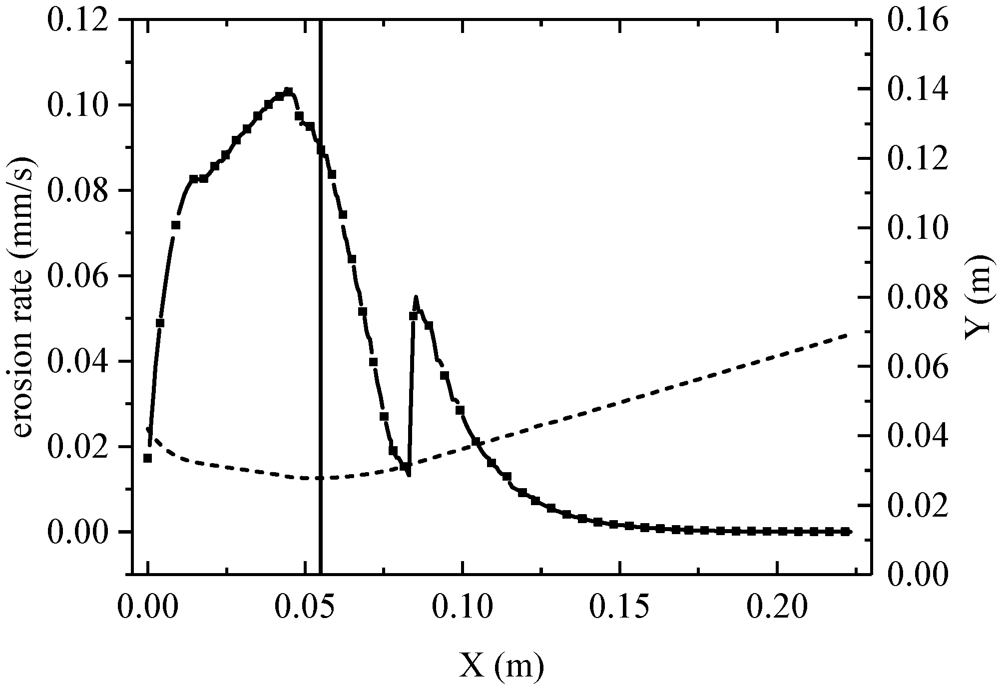
Figure 8 presents the distribution of the average ablation rate along the nozzle inner wall axis during the operation. Along the converging section, the average ablation rate increases rapidly, reaching a maximum at a point slightly upstream of the nozzle throat. The ablation rate then decreases downstream. At the interface between the throat liner and the expansion section, a significant difference in ablation rates is present on either side. The ablation rate of the carbon/phenolic composite on the right side is approximately 0.0394 mm/s higher than that of the C/C composite on the left side. This differential ablation causes the formation of an ablation step of approximately 0.71 mm. Beyond this point, along the axial distance in the carbon/phenolic expansion section, the average ablation rate decreases rapidly.

4.2. Determination of Influencing Factors and Working Conditions

In the field of solid rocket motor research, the ablation of composite nozzles is significantly influenced by multiple factors. To investigate these factors in depth, this study conducted simulations under different working conditions by considering four key aspects: gas pressure, temperature, H2O concentration in the gas, and aluminum concentration in the propellant. For gas pressure, values ranging from 4.86 to 7.86 MPa were selected, and working conditions were set at 1 MPa intervals. The composition of the inlet boundary and the gas flow temperature (3383 K) were kept constant. The nozzle ablation over a 15 s period was calculated for each condition. For the gas temperature, simulations were conducted at 4.86 MPa with four temperature conditions: 3000, 3383, 3600, and 3900 K. For the oxidizing components in the gas, water was chosen as the study subject. Under conditions of 4.86 MPa and 3383 K, simulations were performed for H2O concentration levels of 0.0507, 0.0643, 0.0778, and 0.0914. Four working conditions were established for the aluminum concentration in the propellant [49]. The pressure was maintained at 4.86 MPa, and the temperature was varied between 3300 and 3510 K. The aluminum concentration was set at 15%, 18%, 21%, and 24%.
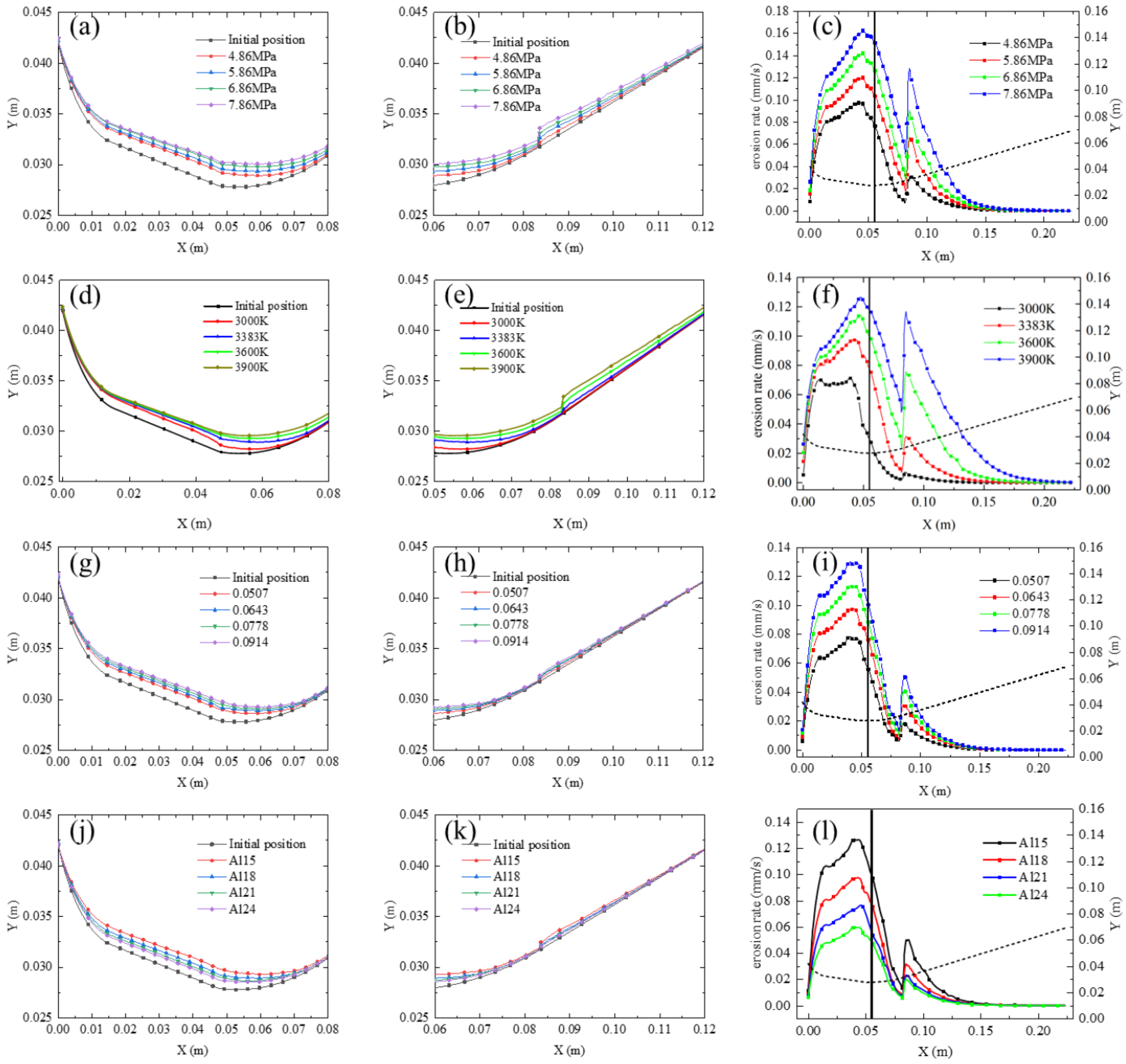
Different working conditions exert varied influences on the boundary layer near the nozzle wall, consequently affecting wall ablation. Therefore, we examined the impact of different factors on the ablation of composite nozzles. The computed results include post-ablation wall profiles and the distribution of the thermochemical ablation rate along the nozzle wall under different conditions of the combustion chamber. Figure 9 presents nozzle-related results under different working conditions, including localized views, close-ups of ablation steps, and the distribution of the average thermochemical ablation rate along the nozzle wall. It is important to note here, in practical operating conditions, these parameters (pressure, temperature, H2O concentration, and aluminum concentration) are inherently interrelated—for example, pressure variations may induce changes in temperature and species concentrations. However, to emphasize the isolated influence of each parameter, this work temporarily excluded their interdependencies.
First, the influence of different factors on ablation rates across different regions was analyzed. Figure 9a,b show the post-ablation nozzle profiles under different combustion chamber pressures. As the combustion chamber pressure increases from 4.86 to 7.86 MPa over the same operating period, both the wall recession and ablation step thickness increase. This is because a higher gas pressure increases the gas mass flow rate, which in turn raises the concentration of the oxidizing component, accelerating the ablation rate. Moreover, the increase in pressure enhances convective heat transfer and mass exchange at the wall, thins the boundary layer, and reduces the resistance to oxidizing component diffusion toward the wall. Furthermore, the higher pressure increases the rate of heterogeneous chemical reactions at the nozzle wall, thereby further intensifying ablation. Figure 9c depicts the axial distribution of the ablation rate along the wall. The ablation pattern follows a consistent trend: in the converging section, the ablation rate increases continuously, reaching its peak just before the throat. The rate then decreases within the throat liner. From the throat liner to the expansion section, significant differences in thermal properties and density between C/C and carbon/phenolic materials result in a steep temperature gradient, causing a sudden rise in the ablation rate and forming an ablation step. Beyond this point, in the expansion section, the ablation rate gradually decreases along the axial direction.
Figure 9d,e display the post-ablation nozzle profiles under different combustion gas temperatures. When the inlet gas temperature is 3000 K, changes in the throat and expansion section profiles are very small. A closer inspection reveals that as the gas temperature increases from 3000 to 3900 K, the extent of wall recession grows, indicating that higher temperatures accelerate wall ablation. Figure 9f presents the distribution of the average ablation rate, exhibiting a trend similar to that in Figure 9c under different temperatures.
Figure 9g,h illustrate the post-ablation nozzle profiles under different H2O concentrations. As the H2O concentration in the gas increases from 0.0507 to 0.0914, the extent of nozzle wall recession increases accordingly. Figure 9i shows that the ablation rate across the entire nozzle inner wall increases as the H2O concentration increases during the operating period. The thermochemical ablation model reveals that when the ablation rate is governed by chemical reaction kinetics, an increase in the H2O concentration directly accelerates its reaction with the wall. When the ablation rate is controlled by the diffusion of oxidizing components to the wall, a higher H2O concentration increases the concentration gradient at the wall, thereby enhancing the diffusion rate. These factors jointly contribute to an increase in the nozzle ablation rate with an increasing H2O concentration.
Figure 9j–l show the post-ablation nozzle inner wall profiles for different aluminum concentrations in the propellant. When the aluminum concentration is 15% (Al15), 18% (Al18), 21% (Al21), and 24% (Al24), both the wall recession and ablation rate decrease as the aluminum concentration increases. Although aluminum combustion releases a large amount of heat and raises the gas temperature, it does not directly intensify nozzle ablation. Aluminum combustion generates aluminum oxide (Al2O3) particles, which may form a relatively dense protective layer on the nozzle wall. This layer impedes further reaction between oxidizing components in the gas and the wall material, thereby reducing the ablation rate and limiting wall recession. Moreover, variations in the aluminum concentrations may alter the flow characteristics of the gas, affecting properties such as viscosity and velocity distribution. These changes, in turn, influence convective heat transfer and mass exchange at the wall, exerting an inhibitory effect on ablation.
Next, the factors influencing step ablation were analyzed. Figure 10 presents the variations in the ablation rate of the throat liner and step thickness in a composite nozzle under different conditions. As shown in Figure 10a, the ablation rate of the throat liner and the step thickness in the composite nozzle generally increase with an increasing pressure, exhibiting an approximately linear relationship. By fitting the throat liner ablation rate and step thickness to the combustion chamber pressure data, we obtain the relationships as r ˙ = 0.0248 P 0.0437 and y = 0.267 x 0.8306 , with R2 values of 0.9991 and 0.9927, respectively. As shown in Fig. 10b, the ablation rate at the throat and the step thickness in the composite nozzle increase with a rising temperature; however, the rate of increase is gradually reduced, especially when the temperature exceeds 3600 K. Higher gas temperatures result in a greater temperature difference between the nozzle wall and the gas, leading to a faster increase in the wall temperature. Consequently, the ablation rate governed by chemical reactions increases. When the wall temperature rises beyond a certain threshold, the ablation rate controlled by chemical reactions surpasses the diffusion rate of oxidizing components to the wall. At this stage, the thermochemical ablation rate is dictated by this diffusion rate rather than the wall temperature. The higher the gas temperature, the faster the wall temperature reaches the transition point for the ablation control mechanism. Consequently, the impact of temperature on the growth of the ablation rate weakens over the entire process. As shown in Figure 10c, an increase in the H2O concentration as an oxidizing component also causes a rise in the throat liner ablation rate and step thickness. As shown in Figure 10d, increasing the aluminum concentration in the propellant slightly increases the gas temperature; however, it simultaneously reduces the concentrations of H2O and CO2 in the gas. Consequently, regardless of whether the ablation rate is controlled by thermochemical reactions or diffusion, the ablation rate decreases. This leads to a reduction in the ablation rate of the C/C throat liner in the composite nozzle and a decrease in the step thickness between the throat liner and the expansion section over the same operation period.
The factors influencing thermochemical ablation in composite nozzles were analyzed from various perspectives. A higher gas pressure was found to lead to increased throat liner ablation rate and step thickness, with a linear relationship between the two. Increases in both the gas temperature and H2O concentration resulted in higher throat liner ablation rates and step thickness, with the presence of oxidizing components increasing these further. Although an increase in the aluminum concentration in the propellant slightly increased the gas temperature, it simultaneously decreased the concentration of oxidizing components in the gas, consequently reducing the throat liner ablation rate and step thickness.

5. Conclusions

The focus in this study was the issue of step ablation in composite nozzles for solid rocket motors, which significantly impacts nozzle performance and engine operational stability. Several investigations were conducted to address this issue.
Modeling and validation: An innovative thermochemical ablation model for composite nozzles was developed. This model considers wall recession and the coupling of multiple physical processes. The ablation models for C/C nozzles and carbon/phenolic composite nozzles were validated using experimental data from the U.S. Air Force Rocket Propulsion Laboratory. The results demonstrated that the model achieved high accuracy.
Analysis of ablation characteristics: Transient ablation simulations were performed on composite nozzles to analyze the thermochemical ablation distribution. The ablation rate of the C/C throat liner was observed to initially increase and then decrease, whereas the ablation rate of the carbon/phenolic expansion section continuously increased over time. At the junction of the two materials, the thermochemical ablation rate suddenly increased, forming an ablation step with a height of 0.71 mm. This phenomenon is attributed to differences in surface density and thermo-physical parameters.
Analysis of influencing factors: Simulations were conducted under different working conditions, considering four key factors: gas pressure, temperature, H2O concentration in the gas, and aluminum concentration in the propellant. The results showed that higher gas pressure led to increased throat liner ablation rate and step thickness, with a linear relationship between the two. Higher gas temperature resulted in increased ablation rates and step thickness; however, when the temperature exceeded 3600 K, the rate of increase slowed down. An increased H2O concentration raised the throat liner ablation rate and step thickness. A higher aluminum concentration in the propellant decreased the throat liner ablation rate and step thickness.
The established model and analysis results from this study provide a theoretical foundation for the thermal protection design and performance optimization of composite nozzles. The findings will help enhance the reliability and service life of solid rocket motor nozzles and advance related technological developments in the field. Furthermore, the ablation competition model, which accounts for multiple influencing factors, enables a more rational selection of ablation control mechanisms and improves the accuracy of ablation rate calculations, laying a solid foundation for future research.

Author Contributions

Conceptualization, J.C.; Methodology, J.C.; Validation, G.Z.; Formal analysis, C.Z.; Investigation, X.F.; Resources, H.Y.; Data curation, C.Z.; Writing—original draft, C.Z., H.Y. and X.F.; Writing—review & editing, G.Z.; Supervision, J.C. All authors have read and agreed to the published version of the manuscript.

Funding

This research received no external funding.

Data Availability Statement

The data presented in this study are available on request.

Conflicts of Interest

The research was conducted in the absence of any commercial or financial relationships that could be construed as a potential conflict of interest, and the authors declare no conflict of interest.

References

  1. Gao, Y.; Liu, Y.; Dong, Z.; Ma, D.; Yang, B.; Qiu, C. Preliminary experimental study on combustion characteristics in a solid engine nozzle based on the TDLAS system. Energy 2023, 268, 126741. [Google Scholar] [CrossRef]
  2. Guo, M.; Du, J.; Zhang, Y. Effect of CNT content and size on the high-temperature particle-erosion resistance of ablative materials for thermal protection systems. Compos. Sci. Technol. 2023, 235, 109969. [Google Scholar] [CrossRef]
  3. Guo, M.; Yu, K.; Yang, J.; Zhang, P.; Zhang, Y.; Zhu, D. B2O3-reinforced ablative materials with superior and comprehensive ablation resistance used in aerospace propulsion TPSs. Polym. Degrad. Stab. 2024, 223, 110740. [Google Scholar] [CrossRef]
  4. Keswani, S.; Kuo, K. An aerothermochemical model of carbon-carbon composite nozzle recession. In Proceedings of the 24th Structures, Structural Dynamics and Materials Conference, Lake Tahoe, NV, USA, 2–4 May 1983. [Google Scholar]
  5. Natali, M.; Torre, L.; Puri, I.; Rallini, M. Thermal degradation of phenolics and their carbon fiber derived composites: A feasible protocol to assess the heat capacity as a function of temperature through the use of common DSC and TGA analysis. Polym. Degrad. Stab. 2022, 195, 109793. [Google Scholar] [CrossRef]
  6. Su, Q.; Zha, B.; Wang, J.; Yan, M.; Gao, Y.; Sun, Z.; Huang, W. Simulation and application of a new multiphase flow ablation test system for thermal protection materials based on liquid rocket engine. Aerospace 2022, 9, 701. [Google Scholar] [CrossRef]
  7. Cardillo, D.; Battista, F.; Gallo, G.; Mungiguerra, S.; Savino, R. Experimental firing test campaign and nozzle heat transfer reconstruction in a 200 N hybrid rocket engine with different paraffin-based fuel grain lengths. Aerospace 2023, 10, 546. [Google Scholar] [CrossRef]
  8. Li, W.; Huang, J.; Zhang, Z.; Wang, L.; Huang, H.; Liang, J. A model for thermal protection ablative material with local thermal non-equilibrium and thermal radiation mechanisms. Acta Astronaut. 2021, 183, 101–111. [Google Scholar] [CrossRef]
  9. Jiang, X.; Tian, H.; Tan, G.; Zhao, S.; Cai, G. Experiments of ablation characteristics for different nozzle materials and transient simulations on thermochemical erosion in hybrid rocket motors. Acta Astronaut. 2023, 212, 455–466. [Google Scholar] [CrossRef]
  10. Tian, H.; He, L.; Yu, R.; Zhao, S.; Wang, P.; Cai, G.; Zhang, Y. Transient investigation of nozzle erosion in a long-time working hybrid rocket motor. Aerosp. Sci. Technol. 2021, 118, 106978. [Google Scholar] [CrossRef]
  11. Meng, X.; Tian, H.; Niu, X.; Zhu, H.; Gao, J.; Cai, G. Long-duration dynamic numerical simulation of combustion and flow in hybrid rocket motors considering nozzle erosion. Aerospace 2024, 11, 318. [Google Scholar] [CrossRef]
  12. Sciti, D.; Vinci, A.; Zoli, L.; Galizia, P.; Failla, S.; Mungiguerra, S.; Di Martino, G.D.; Cecere, A.; Savino, R. Propulsion tests on ultra-high-temperature ceramic matrix composites for reusable rocket nozzles. J. Adv. Ceram. 2023, 12, 1345–1360. [Google Scholar] [CrossRef]
  13. Mungiguerra, S.; Di Martino, G.D.; Savino, R.; Zoli, L.; Silvestroni, L.; Sciti, D. Characterization of novel ceramic composites for rocket nozzles in high-temperature harsh environments. Int. J. Heat Mass Transf. 2020, 163, 120492. [Google Scholar] [CrossRef]
  14. Shang, Y.T. Analysis of Ablation Step Phenomenon and Its Influence on the Performance of Nozzle. Aero Weapon. 2015, 287, 44–47. [Google Scholar]
  15. Tian, H.; Jiang, X.; Yu, R.; Meng, X.; Niu, X.; Cai, G. Research on thermochemical erosion and thermal protection properties of multiple interface nozzles in long-time working hybrid rocket motors. Acta Astronaut. 2023, 204, 143–156. [Google Scholar] [CrossRef]
  16. Gao, Y.; Liu, Y.; Ma, D. Effect of operation pressure on heat release characteristics in solid rocket motor nozzle considering detailed chemical reaction mechanism. Aerosp. Sci. Technol. 2022, 128, 107794. [Google Scholar] [CrossRef]
  17. Rashkovskiy, S.; Yakush, S. Numerical simulation of low-melting temperature solid fuel regression in hybrid rocket engines. Acta Astronaut. 2020, 176, 710–716. [Google Scholar] [CrossRef]
  18. Liu, R.; Chen, X.; Zhou, C.S.; Li, Y. Measurement of erosion morphology in a composite structure nozzle and its influence on flow field. Chin. J. Aeronaut. 2015, 36, 2958–2967. [Google Scholar]
  19. Kan, X.; Wang, K.; Ma, G. Intentional mistuning blade dry friction model for vibration localization of the bladed disk. Thin-Walled Struct. 2025, 208, 112864. [Google Scholar] [CrossRef]
  20. Cornell, R.E.; Burke, M.P. The discovery of non-equilibrium kinetic sequences important to ammonia/co-fuel and propellant flames. Int. J. Therm. Sci. 2024, 40, 105265. [Google Scholar] [CrossRef]
  21. Hao, X.; Yan, Y.; Cao, T.; Li, W.; Zhang, H. Numerical prediction of the two-phase flow and radiation effects on the thermal environment and ablation of solid rocket nozzle. Int. J. Therm. Sci. 2024, 197, 108794. [Google Scholar] [CrossRef]
  22. Huang, W.; Wang, C.; Zhang, K.; Wang, Z.; Tian, W. Study on the Influence of Nozzle Ablation on the Performance of the Solid Rocket Motor. Aerospace 2023, 10, 156. [Google Scholar] [CrossRef]
  23. Shao, S.; Zhang, W.; Yue, S.; Qiao, H.; Liu, P.; Ao, W. Mg content and AP size on the microscale flame structure of Mg-based propellant. Aerosp. Sci. Technol. 2024, 150, 109213. [Google Scholar] [CrossRef]
  24. Golovina, E. The gasification of carbon by carbon dioxide at high temperatures and pressures. Carbon 1980, 18, 197–201. [Google Scholar] [CrossRef]
  25. Acharya, R.; Kuo, K.K. Effect of pressure and propellant composition on graphite rocket nozzle erosion rate. J. Propul. Power 2007, 23, 1242–1254. [Google Scholar] [CrossRef]
  26. Guo, M.; Du, J.; Zhang, Y. ZrO2-reinforced polymer-matrix composites used for thermal protection systems of ultra-high temperature aerospace propulsion. Aerosp. Sci. Technol. 2024, 145, 108906. [Google Scholar] [CrossRef]
  27. Hu, B.; Li, J.; Xu, J.; Bai, H.; Wang, Y. Excellent ablation resistance of silicone insulations reinforced with three carbon-based nano-fillers under oxygen-enriched environment. Acta Astronaut. 2025, 229, 55–64. [Google Scholar] [CrossRef]
  28. Wang, Y.W.; Li, J.; Wan, L.Q.; Wang, L.; Li, K. A lightweight rubber foaming insulation reinforced by carbon nanotubes and carbon fibers for solid rocket motors. Acta Astronaut. 2023, 208, 270–280. [Google Scholar] [CrossRef]
  29. Li, K.; Li, J.; He, Z.; Xu, Q.; Cheng, S. Study on the collision characteristics between high-temperature alumina droplets and char layer. Acta Astronaut. 2024, 225, 870–880. [Google Scholar] [CrossRef]
  30. Libby, P.A.; Blake, T.R. Theoretical Study of Burning Carbon Particles. Combust. Flame 1979, 36, 139–169. [Google Scholar] [CrossRef]
  31. Song, N.; Wu, Y.; Yuan, G.; Hui, S.; Liu, P. Investigation of the effects of alumina particle phase transition on internal flow field and engine performance in solid rocket motors. Phys. Fluids 2024, 36, 123314. [Google Scholar] [CrossRef]
  32. Zhang, X.G.; Wang, C.H.; Liu, Y.; Ren, J. Coupled fluid, thermal and structural analysis of nozzle inserts in solid rocket motors. J. Solid Rocket Technol. 2011, 34, 579–583. [Google Scholar]
  33. Liggett, N.; Menon, S. Simulation of Nozzle Erosion Process in a Solid Propellant Rocket Motor. In Proceedings of the 45th AIAA Aerospace Sciences Meeting and Exhibit, Reno, NV, USA, 8–11 January 2007. [Google Scholar]
  34. Zhang, K.; Wang, C.; Li, Q.; Wang, Z. Characterization of the nozzle ablation rate based on 3D laser scanning system. Aerospace 2023, 10, 172. [Google Scholar] [CrossRef]
  35. Zhang, X.; Wang, Z.; Wang, R.; Lu, C.; Yu, R.; Tian, H. Numerical simulation of chemical ablation and mechanical erosion in hybrid rocket nozzle. Acta Astronaut. 2022, 192, 82–96. [Google Scholar] [CrossRef]
  36. Bianchi, D.; Nasuti, F. Thermochemical Erosion Analysis of Carbon-Carbon Nozzles in Solid-Propellant Rocket Motors. In Proceedings of the 46th AIAA/ASME/SAE/ASEE Joint Propulsion Conference & Exhibit, Nashville, TN, USA, 25–28 July 2010. [Google Scholar]
  37. Zhang, X.G.; Wang, C.H.; Liu, Y.; Ren, J. Carbon-Based Nozzle Thermochemical Erosion Characteristics in Solid Rocket Motors. J. Propuls. Technol. 2012, 33, 93–97. [Google Scholar]
  38. Feng, X.P.; Zhan, H.J.; Wang, L.; Chen, J.; Hou, X. Fluid-Solid Coupling Simulation of Ablation Wall Recession of C/C Composite Nozzle. J. Propuls. Technol. 2022, 43, 200786. [Google Scholar]
  39. Xu, C.; Sun, Z.H. Ablation simulation of carbon/carbon three-dimensional nozzle based on dynamic mesh technique. J. Donghua Univ. 2022, 48, 92–96. [Google Scholar]
  40. He, G.Q.; He, H.Q.; Mao, G.W. Calculation of ablative ‘step effect’ in nozzle divergent section. J. Propuls. Technol. 1990, 6, 19–95. [Google Scholar]
  41. Bai, T.T.; Sun, Z.H. Numerical Simulation on Heat Transfer and Ablation for the Nozzle of a Solid Rocket Motor. J. Proj. 2022, 42, 119–124. [Google Scholar]
  42. Bianchi, D.; Turchi, A.; Nasuti, F. Numerical Analysis of Nozzle Flows with Finite-Rate Surface Ablation and Pyrolysis-Gas Injection. In Proceedings of the 47th AIAA/ASME/SAE/ASEE Joint Propulsion Conference and Exhibit, San Diego, CA, USA, 31 July–3 August 2011. [Google Scholar]
  43. Guo, M.; Zhang, P.; Yu, K.; Yang, J.; Wang, H.; Zhang, Y.; Du, J.; Zhu, D. Hollow microsphere-reinforced ablative materials for thermal protection systems of solid rocket motors. Acta Astronaut. 2024, 221, 309–317. [Google Scholar] [CrossRef]
  44. Zhang, W.; Hu, S.; Li, H.; Song, T.; Jiang, L.; Zhang, Q.; Zhang, S.; Lu, Y.; Zhang, L. Epoxidized vinyl silicone rubber-based flexible ablative material with low linear ablation rate. Compos. Commun. 2023, 40, 101606. [Google Scholar] [CrossRef]
  45. Geisler, R.; Beckman, C. The History of the BATES motors at the Air Force Rocket Propulsion Laboratory. In Proceedings of the 34th AIAA/ASME/SAE/ASEE Joint Propulsion Conference and Exhibit, Cleveland, OH, USA, 13–15 July 1998; p. 3981. [Google Scholar]
  46. Klager, K. The Interaction of the Efflux of Solid Propellants with Nozzle Materials. Propellants Explos. Pyrotech. 1977, 2, 55–63. [Google Scholar] [CrossRef]
  47. Fang, D.Y.; Xia, Z.X.; Jiang, C.L. Engineering Calculation of C/C Throat Insert Ablation. J. Solid Rocket Technol. 2000, 2, 24–27. [Google Scholar]
  48. Zhang, B.; Liu, Y.; Wang, C.; Ren, J. New discrimination method for ablative control mechanism in solid-propellant rocket nozzle. Sci. China Technol. Sci. 2010, 53, 2718–2724. [Google Scholar] [CrossRef]
  49. Thakre, P.; Yang, V. Chemical Erosion of Carbon-Carbon/ Graphite Nozzles in Solid-Propellant Rocket Motors. J. Propuls. Power 2008, 24, 822–833. [Google Scholar] [CrossRef]
Figure 1. Computational model of the composite nozzle [45].
Aerospace 12 00499 g001
Figure 2. Unsteady-state ablation calculation process for the composite nozzle.
Aerospace 12 00499 g002
Figure 3. Validation of the proposed nozzle ablation model: (a) C/C 70-lb BATES engine [4]; (b) distribution curve of the thermochemical ablation rate on the nozzle wall (the dotted line represents the profile inside the nozzle).
Aerospace 12 00499 g003
Figure 4. Validation of the carbon/phenolic composite computational model: (a) carbon/phenolic composite computational model; (b) thermochemical ablation distribution curves on the nozzle wall (the dotted line represents the profile inside the nozzle).
Aerospace 12 00499 g004
Figure 5. Temperature distribution (ad), Mach number (eh), and pressure (il) contours in the computational domain at different times.
Aerospace 12 00499 g005
Figure 6. Wall temperature distribution curves and nozzle inner wall ablation rates at different times: (a) wall temperature distribution curves; (b) nozzle inner wall ablation rate curves. (The dotted line represents the profile inside the nozzle, and the vertical line in (b) represents the location of the nozzle throat.)
Aerospace 12 00499 g006
Figure 7. Distribution of H2O and CO2 ablation rate control regimes at the step at 18 s: (a) H2O ablation rate control regime distribution; (b) CO2 ablation rate control regime distribution. (The dotted line represents the profile inside the nozzle, and vertical dotted line represents the location of the ablation step.)
Aerospace 12 00499 g007
Figure 8. Average nozzle ablation rate during operating time (the dotted line represents the profile inside the nozzle, and the vertical line represents the location of the nozzle throat).
Aerospace 12 00499 g008
Figure 9. Localized views, close-ups of ablation steps, and the distribution of the average thermochemical ablation rate along the nozzle wall under different working conditions for four influencing factors: (ac) calculated results for different gas pressures; (df) calculated results for different gas temperatures; (gi) calculated results for different H2O concentrations; (jl) calculated results for different aluminum concentrations. (dotted lines in (c,f,i,l) represent the profile inside the nozzle, and the vertical line represents the location of the nozzle throat.)
Aerospace 12 00499 g009
Figure 10. Variations in throat liner ablation rate and step thickness under different conditions: (a) ablation rate and step thickness at different gas pressures; (b) ablation rate and step thickness at different gas temperatures; (c) ablation rate and step thickness at different H2O concentrations; (d) ablation rate and step thickness at different aluminum concentrations.
Aerospace 12 00499 g010
Disclaimer/Publisher’s Note: The statements, opinions and data contained in all publications are solely those of the individual author(s) and contributor(s) and not of MDPI and/or the editor(s). MDPI and/or the editor(s) disclaim responsibility for any injury to people or property resulting from any ideas, methods, instructions or products referred to in the content.