Abstract
The control accuracy and stability requirements for rotating payloads in remote sensing satellites are becoming increasingly higher. Typically, rotating payloads such as cameras are connected to the satellite body through mechanical bearings. However, clearances in conventional mechanical bearings are inevitable due to assembly tolerances, manufacturing errors, and wear. When clearances exist in the mechanical bearings of cameras, the clearance between the mechanical bearing and the journal can cause impact-induced vibrations. This paper proposes the implementation of magnetic bearings instead of mechanical bearings to connect the payload with the spacecraft body. First, the magnetic bearing is modeled as a rotational joint with clearance in the dynamic system with magnetic constraints. Subsequently, radial and axial magnetic force models are established. Furthermore, a comparative analysis is conducted to investigate the effects of connection approaches, namely traditional mechanical bearing connections and magnetic bearing connections for rotating payloads. Simultaneously, the dynamic responses of rotating payloads under different connections are discussed. The simulation results demonstrate that the camera attitude motion accuracy is improved and the vibration amplitude under disturbance is reduced when using magnetic bearings. Consequently, the magnetic bearing can effectively isolate vibrations and mitigate disturbances, thereby significantly reducing the attitude shake of rotating payloads.
1. Introduction
Optical satellite observation obtains high-quality Earth image information through its optical payloads and is widely used in fields such as atmospheric science, meteorological observation, and ecology. With the further application of optical satellites, users have increasing requirements for the accuracy of observation. Wu et al. [1] proposed a novel type of rotating scan optical satellite, consisting of a spacecraft body and a rotating scanning time-delayed and integration charge-coupled device (TDICCD) camera interconnected via a mechanical bearing.
An important factor influencing observation accuracy is the bearing performance at the junction between the camera and spacecraft body. Mechanical bearings with clearance may cause collisions and impacts between mechanisms, thereby inducing camera vibrations that compromise remote sensing accuracy. In addition, the high rigidity of mechanical bearing connections makes them prone to induce high-frequency vibrations in the camera. Extensive research has been conducted on the modeling and dynamic analysis of mechanisms with clearance. Refs. [2,3,4,5] employed surrogate models to investigate the dynamics of the clearance mechanism. The results indicated that the inevitable clearance in the joints of the mechanisms has a significant effect on the dynamic performance. Brutti et al. [6] modeled the revolute joint with clearance by introducing a nonlinear equivalent force, considering the contact elastic deformations. However, the axial clearances were not considered in the established model. In an advancement, Yan et al. [7] proposed a model for three-dimensional revolute joints with radial and axial clearances; it presents a comprehensive description of the contact modes and can be applied to investigate the nonlinear dynamics of a four-bar mechanism. The simulation results revealed that axial clearances may lead to the bearing rotation, thereby generating the out-of-plane motion of the mechanism. The three-dimensional clearance model introduces more intricate collision scenarios, posing significant challenges for collision detection algorithms. Li et al. [8] proposed a contact state detection method for revolute clearance joints based on the finite particle method (FPM) and validated that clearance has significant influences on the dynamic responses of the Bennett linkage deployment. Zhang and Wang [9] established two contact detection algorithms for a frictional translational joint with two states of stick and slip based on kineto-elasto-dynamic method and varying penalty factors, avoiding convergence difficulties and enforcing the accuracy. Furthermore, scholars have applied refined clearance models to investigate more intricate clearance mechanisms. Chen and Yang [10] evaluated the dynamic response of a parallel mechanism with both radial and axial clearances, revealing that the clearance has little influence on displacement and velocity but great influence on acceleration and contact force. Bai and co-researchers [11,12,13,14] investigated the dynamic characteristics of a mechanical system considering radial and axial mixed clearances in a three-dimensional revolute joint using computational methodology, and the contact characteristics of the joint, including the contact force and frequency, are obviously oscillating, which is attributable to the clearances. Consequently, clearances induce collision to mechanisms, generating irregular displacement and sudden changes in contact force and acceleration, reducing the accuracy of rotating payloads.
Unlike mechanical bearing systems, magnetic bearing systems offer a distinct advantage by levitating the camera shaft via electromagnetic forces, thereby eliminating physical contact at the bearing interface. Moreover, this configuration enables active adjustment of the camera’s position and attitude [15], providing variable stiffness and damping characteristics. Currently, magnetic bearings have been successfully implemented in practical applications of satellite attitude-control flywheels and related fields [16,17,18]. Due to the numerous factors affecting the dynamic characteristics of magnetic bearings, scholars have paid attention to the establishment of refined models, including parameter identification models [19,20,21] and refined magnetic circuit models [22,23]. Similar to mechanical bearings, magnetic bearings still exhibit vibrations induced by clearance, necessitating active magnetic bearing (AMB) vibration models to support high-precision control. Considering the clearance variation model, Zhao and co-researchers [24,25,26] established a dynamic model of the five DOF AMBs used in the Earth-oriented satellite system with an unbalanced rotating payload. Based on the proposed dynamic model, the high-precision control of a rotating payload satellite considering static and dynamic unbalance disturbance is realized. Yao et al. [27] developed a new model of the vibration transmission path of AMBs, and the main factors that affect the vibration transmission of magnetic bearings utilizing a finite element model were investigated.
The objective of this work is to investigate the motion performances of the satellite system when the rotating payloads are connected to the spacecraft body using mechanical bearings and magnetic bearings. Consequently, this study proposes replacing the mechanical bearings at the joint between the optical rotating payloads and satellite body with magnetic bearings. In Section 2 and Section 3, a contact force constraint model for mechanical bearings and a magnetic force constraint model for magnetic bearings are established. By refining these models, idealized displacement constraints are transformed into force constraints that reflect physical reality better. In Section 4, simulation analyses of satellite and payload attitudes under multiple conditions are conducted. The comparative evaluation of the dynamic responses under different connection configurations demonstrates that the payload vibration is reduced, validating the performance superiority of magnetic bearings.
2. Dynamics Modeling of Mechanical Bearing with Clearance Joint
2.1. Definition of Clearance in Mechanical Revolute Joint
In reality, clearances in a mechanical joint always exist due to assemblage, manufacturing errors, and wear. In general, the clearance joints included in a satellite camera are revolute joints. The difference in radius between the bearing and journal defines the size of radial clearance, which is represented as , where and are the radii of bearing and journal, respectively. When clearance is presented in a revolute joint, the two kinematic constraints are removed, and two degrees of freedom are introduced instead. The dynamics of the clearance joint are then controlled by contact forces working on the journal and bearing [14].
The contact and impact are the typical phenomena of the mechanical clearance joint with clearance. Figure 1 describes the contact between the bearing and the journal. The constraints of the clearance joint are modeled as contact force constraints.
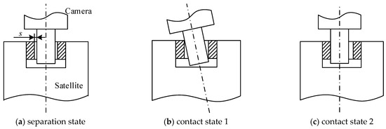
Figure 1.
Contact states in revolute clearance joint.
2.2. Contact Force Model in Mechanical Revolute Joint
The contact force model of the clearance joint should be carefully established to efficiently evaluate the contact forces. Therefore, many contact force models were proposed in the literature [28,29,30,31,32]. One of the contact models proposed by Hertz represents the contact force as a nonlinear function of the penetration based on the purely elastic nature and ignores the energy loss during the impact. Then, in order to account for the energy dissipation in the contact process, Lankarani and Nikravesh [32] proposed a continuous contact force model considering the hysteretic damping factor, which separates the contact force into two sections of elastic and dissipative components. The Lankarani–Nikravesh contact force model is expressed as:
where is the deformation. is the relative deformation velocity. is the damping coefficient. is the contact stiffness coefficient, and it is obtained from Equations (2) and (3):
where , are Poisson’s ratio and Young’s modulus of the k body, respectively. and are radii of the revolute joint elements.
3. Dynamics Modeling of Magnetic Bearing
Magnetic bearings generate magnetic force to suspend the rotating shaft in the space without contact and have the advantages of no friction, high speed, and large bearing capacity.
3.1. Structures of Magnetic Bearing
As shown in Figure 2, the magnetic bearing system consists of a rotor, an axial magnetic bearing, two radial magnetic bearings, and a protection bearing. The axial magnetic bearing constrains the translational DOF of the rotor along the Z-axis, and the two radial magnetic bearings constrain the translational DOF of the rotor along the X-axis and Y-axis, respectively. The protection bearing prevents the rotor from destroying the magnetic bearing, which is caused by sudden power failure and excessive disturbance. The displacement sensor detects the displacement of the rotor, and the controller adjusts the magnetic force of the magnetic bearing.
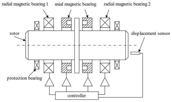
Figure 2.
Mechanical structure of the magnetic bearing system.
3.2. Axial Magnetic Force in Magnetic Bearing
The translational DOF of the rotor along the Z-axis is constrained by the magnetic force of the axial magnetic bearing. As shown in Figure 3, and are the magnetic force from the two stators of the magnetic bearing, respectively; is initial clearance; is the displacement of the rotor centroid; , is the actual clearance to the stator 1 and the stator 2, respectively.
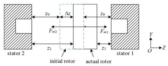
Figure 3.
Axial magnetic bearing.
The displacement of the rotor centroid makes the bearing clearance to the stator 1 decrease and the clearance to the stator 2 increase. And the clearance to the two sides can be expressed as:
Let the current on the stator 1 and the current on the stator 2 be expressed by initial current and offset current :
Combined with the linear magnetic force of one stator:
where is the magnetic force, related to current and clearance ; is the initial magnetic force; is the force–current coefficient; is the force–displacement coefficient; and is the initial clearance. It is worth noting that , , , and are constants, which are related only to the mechanical structure of the axial magnetic bearing.
The magnetic force of the axial magnetic bearing can be expressed as:
where , are the magnetic force of the two sides of the axial magnetic bearing, respectively; and are force–current coefficients and force–displacement coefficients of the axial bearing, respectively. Consequently, the magnetic force in the Z direction can be expressed as:
3.3. Radial Magnetic Force in Magnetic Bearing
As shown in Figure 4, the radial magnetic bearing is configured with two pairs of magnetic stators to control the axial displacement of the rotor in both the X and Y directions. According to the displacement offset detected by the sensors, the magnetic force will be adjusted by the controller to eliminate the changes in the clearance. According to the Equation (7), the magnetic force can be expressed as:
where is the magnetic force; is the force–current coefficients, and is the force–displacement coefficients of the radial bearing; the subscripts and indicate the axis on which the stator is located.
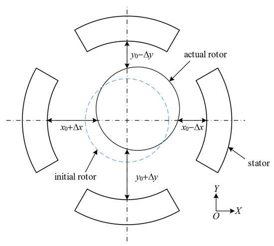
Figure 4.
Radial magnetic bearing.
3.4. Dynamics Equations of Multibody System with Clearance Joint
Generally, the dynamic governing equations of a multibody system can be characterized by a set of differential algebraic equations (DAEs). The dynamics equations of the mechanism system are established considering the clearance model. The clearance leads to two different motion phases of bodies connected with the clearance joint: one is when the bodies move freely in the clearance, and the other is when the bodies contact and interact. Therefore, the mechanism system with clearance between bodies is a variable topology system, which is solved using the dynamic segmentation modeling method. Furthermore, the dynamics equation is obtained using the Lagrange multiplier method.
In the free motion phase, the dynamics equation is presented as [33]:
where is the generalized coordinate column matrix, , , and are the generalized mass matrix, generalized damp matrix, and generalized stiffness matrix, respectively. is the Jacobin matrix of the constraint equation. is the generalized force matrix. is the Lagrange multiplier column matrix.
In the contact phase, the bodies interact, and the contact forces exist in the clearances. The dynamics equation is presented as:
In Equation (11), is the constraint forces resulting from the connected clearance joint. Here, there are two connection constructions to calculate . One is that is the contact force resulting from the mechanical clearance bearing in the case that the payload is connected to the spacecraft body using the traditional mechanical bearing. The other is that is the magnetic force resulting from the magnetic bearing in the case that the payload is connected to the spacecraft body using the magnetic bearing.
The dynamics modeling process of the magnetic suspension camera and mechanical support camera is basically the same. The main difference is that the magnetic forces in the magnetic bearing are controllable.
4. Dynamics Simulation Results and Discussion
4.1. Structure of the Spacecraft with Rotation Payloads
The satellite system studied in this paper consists of the spacecraft body, the solar panels, and the camera. The spacecraft body and the camera can be regarded as a rigid body; the solar panel is a flexible body, and the motion of the camera relative to the spacecraft body is constrained by the magnetic force using the magnetic bearing. The satellite structure is shown in Figure 5, and the parameters of each component are shown in Table 1.
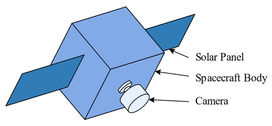
Figure 5.
Satellite structure.

Table 1.
Parameters of satellite components.
4.2. Simulation Results of Satellite Attitude
In this section, the connection modes between the camera and the spacecraft body are simulated, respectively, in three cases: (a) rotation pair without clearance, (b) rotation pair with 0.1 mm clearance, and (c) magnetic bearing. At the beginning of the simulation, the satellite has the initial angular velocity , while the camera stays static. In the simulation process, the satellite is not affected by external forces, and the simulation time is . According to the parameters of the magnetic bearings, the values of the coefficients are listed in Table 2.

Table 2.
Values of coefficients.
The magnetic bearing controller adopts the PD control, where the controller parameters of the axial magnetic bearing are , ; the controller parameters of radial magnetic bearing are , . The simulation results are shown in Figure 6.
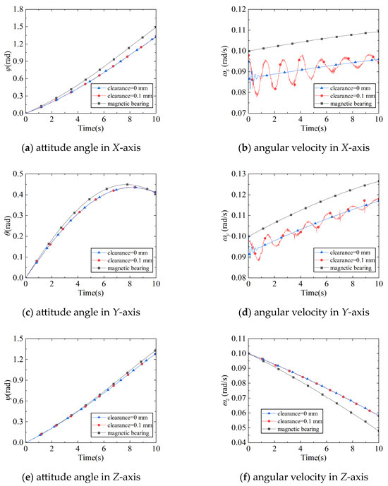
Figure 6.
Satellite attitude angles and angular velocities with different connection modes.
In the dynamics simulation, the coupling of satellite attitude angles exists due to the fact that the inertia product of the satellite system is not zero, according to Figure 6a,c,e. As the simulation time increases, the attitude angle is coupled with other attitude angles gradually; it increases first and then decreases near the end of the simulation. From Figure 6b,d, the simulation results indicate that the connection with the clearance exhibits a significant decrease in angular velocity along both the X-axis and Y-axis during the initial phase compared to the clearance-free connection. This is attributed to the impact effect induced by the clearance, where the camera exerts an impulsive force on the satellite in a direction opposite to the satellite’s motion direction, thereby reducing its angular velocity. During subsequent simulation phases, the presence of clearance allows the camera shaft to move within the clearance and repeatedly collide with the walls, resulting in continuous fluctuations in the satellite’s angular velocity.
The magnetic bearing connection exhibits a phenomenon similar to the connection with clearance during the initial simulation phase. This phenomenon occurs because relative motion arises between the spacecraft body and the camera. The magnetic bearing adjusts its magnetic force to maintain camera alignment with the spacecraft body. While accelerating the camera to synchronize with the satellite’s movement, the system inevitably reduces the spacecraft body’s angular velocity. As the simulation progresses, through continuous adaptive adjustments over time, the camera achieves stable tracking of the satellite’s motion without oscillations.
4.3. Simulation Results of Satellite Maneuver
During the on-orbit operation of satellite cameras, attitude jitter caused by satellite maneuvers, satellite platform vibrations, and external disturbances to the camera itself can degrade the quality of acquired images. This section investigates the camera’s attitude characteristics during satellite maneuvers and analyzes the impact of different camera connected configurations, including those connected with a mechanical bearing and those connected with a magnetic bearing.
4.3.1. Satellite Attitude Sinusoidal Maneuver
The sinusoidal attitude maneuver strategy refers to a motion planning method where the angular acceleration profile follows a sinusoidal function, ensuring no abrupt changes in angular acceleration. In this section, simulations of cameras connected to the satellite via mechanical bearings and magnetic bearings are conducted under this sinusoidal maneuver scheme. The sinusoidal maneuver scheme is depicted in Figure 7.

Figure 7.
Satellite attitude sinusoidal maneuver.
The attitude angle , angular velocity , and angular acceleration during the maneuver are as follows:
where , , , . The simulation results are shown in Figure 8.
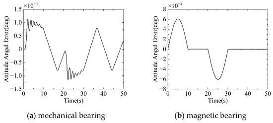
Figure 8.
Attitude sinusoidal maneuver results: camera attitude angle error.
In Figure 8, the attitude angle error of the camera connected by the mechanical bearing reaches a maximum of , while the camera connected by the magnetic bearing presents a maximum error of . This shows that the camera achieves a better performance. Figure 8a reveals that clearance-induced collisions between the journal and bearing at the simulation start cause camera vibrations. When the camera’s acceleration is non-zero (T = 0~10 s and T = 20~30 s), time-decaying oscillations emerge in the attitude angles. Post-maneuver, persistent non-zero attitude angle errors with fluctuating patterns indicate unresolved journal–bearing collisions. In contrast, Figure 8b shows slight attitude angle errors throughout the magnetic bearing maneuver, achieving near-zero errors post-maneuver, demonstrating significant advantages over the mechanical bearings.
4.3.2. Satellite Attitude Polynomial Maneuver
The polynomial attitude maneuver scheme refers to a motion planning method where the angular acceleration profile follows a polynomial function. In this section, the attitude maneuver scheme employs a quintic polynomial, which ensures that the angular acceleration during attitude maneuvers exhibits a smooth variation without abrupt changes. Notably, this scheme eliminates the constant velocity phase during the attitude maneuver. The resulting attitude maneuver scheme is illustrated in Figure 9, and the mathematical expressions for attitude angle , angular velocity , and angular acceleration during the maneuver are as follows:
where , , , , , . The simulation results are shown in Figure 10.

Figure 9.
Satellite attitude polynomial maneuver.
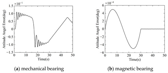
Figure 10.
Attitude polynomial maneuver results: camera attitude angle error.
It can be seen from Figure 10 that the attitude angle error of the camera connected by the mechanical bearing is below , whereas the camera connected by the magnetic bearing exhibits a maximum error of . This shows that the camera achieves a better performance. According to Figure 10a, due to the clearance, the camera connected by mechanical bearings collided with the satellite twice within 20 s at the beginning of the simulation. After the collision, the attitude angle error curve between the camera and the satellite will jitter and gradually decay. The attitude jitter amplitude is 0.04 deg, and the tracking error is a maximum of 0.11 deg. According to Figure 10b, the attitude angle error of the camera connected by magnetic bearings changes gently during the whole maneuver process; there is no jitter, and the tracking error does not exceed . Comparing the two camera connection schemes, it is found that the attitude angle of the satellite camera using the magnetic bearing is more stable, and the tracking error is much smaller than that of the satellite using the mechanical bearing.
4.4. Simulation Results During Disturbing Moments
During in-orbit Earth observation, the operation of internal satellite components generates disturbance torques that degrade the camera’s pointing accuracy. This section evaluates the influence of flywheel-induced disturbance torques on the camera’s pointing accuracy.
The dynamic imbalance of satellite-mounted flywheels induces disturbance torques that directly degrade the camera’s pointing accuracy. When the flywheel rotates in the Z direction, the interference torque along the X-axis and Y-axis is:
where the dynamic imbalance coefficient is , and the angular velocity of the flywheel is . The simulation results are shown in Figure 11.
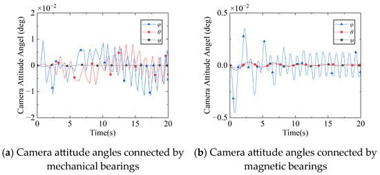
Figure 11.
Camera attitude angle under flywheel interference torque.
In Figure 11a, due to the clearance, the attitude angle of the camera connected by mechanical bearings vibrates violently, with a maximum amplitude of 0.01 deg and a vibration frequency of 0.4 Hz. According to Figure 11b, the vibration amplitude of the camera connected by the magnetic bearing does not exceed and decreases to after a period of time. It can be seen that the magnetic bearing can significantly reduce the influence of interference torque on camera attitude response.
5. Conclusions
In this paper, two kinds of camera connection schemes using mechanical bearings and magnetic bearings are used to simulate the satellite’s stable and maneuvering conditions. Compared with mechanical bearings, magnetic bearings keep the rotor in a suspended state using magnetic force without friction or lubrication, and therefore without mechanical losses. Adjusting magnetic force can control the position of the rotor and enable precise axial and radial displacement of the rotor. And it can actively control the unbalanced interference that causes vibration; so, the advantages of magnetic bearings can effectively improve the control accuracy and stability of satellite payloads. The simulation results show that during the satellite maneuver, the maximum error of the camera connected by the magnetic bearing is on the order of 10−4 deg. The vibration amplitude of the camera connected by the magnetic bearing under disturbing moments is on the order of 10−3 deg. The attitude changes more smoothly compared with the camera connected by mechanical bearings in satellite maneuvering. In the satellite’s stable state, the camera connected by magnetic bearings exhibits the anti-disturbance capability to reduce vibration amplitude, which outperforms the camera connected with mechanical bearings. Based on the operational scenario of rotating payloads connected with magnetic bearings, a comprehensive analysis of vibration survivability, thermal stability, dynamic controller design, and other mission-critical performances across the full mission will be investigated in the future.
Author Contributions
Conceptualization, Z.B.; methodology, Z.B. and J.P.; software, J.P.; validation, Y.D. and Z.B.; formal analysis, Z.B. and J.P.; investigation, J.P. and Y.D.; data curation, J.P. and Y.D.; writing—original draft preparation, Y.D.; writing—review and editing, Z.B.; visualization, Y.D.; supervision, Z.B.; project administration, Z.B. All authors have read and agreed to the published version of the manuscript.
Funding
This work is supported by the Natural Science Foundation of Shandong Province (ZR2023ME171).
Data Availability Statement
All the data used in this investigation are presented in the paper.
Conflicts of Interest
The authors declare no conflicts of interest.
Nomenclature
| generalized damp matrix | |
| damping coefficient | |
| Young’s modulus | |
| generalized force matrix | |
| constraint forces resulting from the connected clearance joint | |
| magnetic force | |
| , , | magnetic forces along each axis direction |
| contact force | |
| initial current on the stator | |
| , | actual current on the stator |
| contact stiffness coefficient | |
| generalized stiffness matrix | |
| force–current coefficient | |
| force–displacement coefficient | |
| , , | force–current coefficient components of magnetic bearings |
| , , | force–displacement coefficient components of magnetic bearings |
| generalized mass matrix | |
| generalized coordinate column matrix | |
| radius of bearing | |
| radius of journal | |
| , | radii of revolute joint elements |
| actual clearance of magnetic bearing | |
| , | interference torque |
| , , | initial clearances of magnetic bearing |
| , | actual clearances of magnetic bearing |
| angular acceleration | |
| contact deformation | |
| , , | displacements of the rotor centroid |
| offset current on the stator | |
| attitude angle | |
| Lagrange multiplier column matrix | |
| dynamic imbalance coefficient | |
| Poisson’s ratio | |
| Jacobin matrix of constraint equation | |
| angular velocity |
References
- Wu, F.; Cao, X.; Butcher, E.A.; Wang, F. Dynamics and Control of Spacecraft with a Large Misaligned Rotational Component. Aerosp. Sci. Technol. 2019, 87, 207–217. [Google Scholar] [CrossRef]
- Wei, X.; Li, N.; Ding, W. Chaotic Motion Control of a Vibro-Impact System Based on Data-Driven Control Method. J. Vib. Control 2023, 29, 148–157. [Google Scholar] [CrossRef]
- Erkaya, S. Prediction of Vibration Characteristics of a Planar Mechanism Having Imperfect Joints Using Neural Network. J. Mech. Sci. Technol. 2012, 26, 1419–1430. [Google Scholar] [CrossRef]
- Ma, J.; Dong, S.; Chen, G.; Peng, P.; Qian, L. A Data-Driven Normal Contact Force Model Based on Artificial Neural Network for Complex Contacting Surfaces. Mech. Syst. Signal Proc. 2021, 156, 107612. [Google Scholar] [CrossRef]
- Singh, A.; Moore, K.J. Characteristic Nonlinear System Identification of Local Attachments with Clearance Nonlinearities. Nonlinear Dyn. 2020, 102, 1667–1684. [Google Scholar] [CrossRef]
- Brutti, C.; Coglitore, G.; Valentini, P.P. Modeling 3D Revolute Joint with Clearance and Contact Stiffness. Nonlinear Dyn. 2011, 66, 531–548. [Google Scholar] [CrossRef]
- Yan, S.; Xiang, W.; Zhang, L. A Comprehensive Model for 3D Revolute Joints with Clearances in Mechanical Systems. Nonlinear Dyn. 2015, 80, 309–328. [Google Scholar] [CrossRef]
- Li, S.; Zheng, Y.; Wu, H.; Zhang, J.; Ohsaki, M.; Yang, C.; Luo, Y. Dynamics Analysis of Deployment Process of the Bennett Linkage with Revolute Clearance Joints. Nonlinear Dyn. 2024, 112, 10911–10935. [Google Scholar] [CrossRef]
- Zhang, J.; Wang, Q. Modeling and Simulation of a Frictional Translational Joint with a Flexible Slider and Clearance. Multibody Syst. Dyn. 2016, 38, 367–389. [Google Scholar] [CrossRef]
- Chen, X.; Yang, W. Dynamic Modeling and Analysis of Spatial Parallel Mechanism with Revolute Joints Considering Radial and Axial Clearances. Nonlinear Dyn. 2021, 106, 1929–1953. [Google Scholar] [CrossRef]
- Bai, Z.; Liu, T.; Li, J.; Zhao, J. Numerical and Experimental Study on Dynamic Characteristics of Planar Mechanism with Mixed Clearances. Mech. Based Des. Struct. Mech. 2023, 51, 6142–6165. [Google Scholar] [CrossRef]
- Bai, Z.; Sun, Y. A Study on Dynamics of Planar Multibody Mechanical Systems with Multiple Revolute Clearance Joints. Eur. J. Mech. A-Solids 2016, 60, 95–111. [Google Scholar] [CrossRef]
- Jiang, X.; Bai, Z. Deployment Dynamics of the Solar Array System with Clearance Joints Considering Interval Uncertainties. Nonlinear Dyn. 2024, 113, 6447–6464. [Google Scholar] [CrossRef]
- Bai, Z.; Jiang, X.; Li, J.Y.; Zhao, J.J.; Zhao, Y. Dynamic Analysis of Mechanical System Considering Radial and Axial Clearances in 3D Revolute Clearance Joints. J. Vib. Control 2021, 27, 1893–1909. [Google Scholar] [CrossRef]
- Sun, R.; Zhu, C. All-Coefficient Adaptive Control of Active Magnetic Bearing System Based on Characteristic Model. In Proceedings of the 2022 25th International Conference On Electrical Machines And Systems (ICEMS 2022), Chiang Mai, Thailand, 29 November 2022–2 December 2022; IEEE: New York, NY, USA, 2022. [Google Scholar]
- Faraji, F.; Majazi, A.; Al-Haddad, K. A Comprehensive Review of Flywheel Energy Storage System Technology. Renew. Sust. Energ. Rev. 2017, 67, 477–490. [Google Scholar] [CrossRef]
- Hsiao, D.-C.; Hsieh, M.-F. Design and Implementation of Novel Homopolar Magnetic Bearings Incorporated in Reaction Wheel for Satellite Attitude Control. IEEE Access 2023, 11, 66374–66381. [Google Scholar] [CrossRef]
- Chen, F.; Wang, W.; Wang, S. Rotating Lorentz Force Magnetic Bearings’ Dynamics Modeling and Adaptive Controller Design. Sensors 2023, 23, 8543. [Google Scholar] [CrossRef]
- Sankar, B.; Sekhar, A.S.; Jana, S. Estimation of Magnetic Bearing Constant in Active Magnetic Bearings. Mech. Syst. Signal Proc. 2023, 198, 110411. [Google Scholar] [CrossRef]
- Tiwari, R.; Chougale, A. Identification of Bearing Dynamic Parameters and Unbalance States in a Flexible Rotor System Fully Levitated on Active Magnetic Bearings. Mechatronics 2014, 24, 274–286. [Google Scholar] [CrossRef]
- Kumar, P.; Tiwari, R. Identification in a Magnetically Levitated Rigid Rotor System Integrated with Misaligned Sensors and Active Magnetic Bearings. J. Vib. Eng. Technol. 2024, 12, 9009–9030. [Google Scholar] [CrossRef]
- Wang, D.; Wang, N.; Ye, C.; Chen, K. Research on Analytical Bearing Capacity Model of Active Magnetic Bearings Based on Magnetic Saturation. IET Electr. Power Appl. 2017, 11, 1548–1557. [Google Scholar] [CrossRef]
- Zhu, Y.; Yang, D.; Gao, X.; Ma, Z. Fractional Modeling and Identification of Active Magnetic Bearings With Laminated and Nonlaminated Structures Including Eddy Currents. IEEE Trans. Transp. Electrif. 2024, 10, 2423–2433. [Google Scholar] [CrossRef]
- Zhao, Y.; Chen, X.; Wang, F.; Wei, C.; Zhao, Y. Modeling of Active Magnetic Bearing in Rotating Payload Satellite Considering Shaft Motion Coupling. J. Mech. Sci. Technol. 2020, 34, 4423–4437. [Google Scholar] [CrossRef]
- Zhao, Y.; Wei, C.; Wei, Q.; Zhao, Y. High Precision Control of Rotating Payload Satellite Considering Static and Dynamic Unbalanced Disturbance. Int. J. Aerosp. Eng. 2022, 2022, 8281092. [Google Scholar] [CrossRef]
- Zhao, Y.; Wei, C.; Yue, C.; Cao, X. Payload-Oriented Control Scheme for Rotating Payload Satellite Considering Inertia Uncertainties and Measurement Errors. Chin. J. Aeronaut. 2023, 36, 335–352. [Google Scholar] [CrossRef]
- Yao, Y.; Ma, Y.; Su, Y.; Su, J.; Yu, S. Vibration Isolation Optimized Design of Magnetic Suspended Pump. Int. J. Appl. Electromagn. Mech. 2020, 63, 81–103. [Google Scholar] [CrossRef]
- Xiang, W.; Yan, S. Dynamic Analysis of Space Robot Manipulator Considering Clearance Joint and Parameter Uncertainty: Modeling, Analysis and Quantification. Acta Astronaut. 2020, 169, 158–169. [Google Scholar] [CrossRef]
- Xiang, W.; Yan, S.; Wu, J.; Niu, W. Dynamic Response and Sensitivity Analysis for Mechanical Systems with Clearance Joints and Parameter Uncertainties Using Chebyshev Polynomials Method. Mech. Syst. Signal Proc. 2020, 138, 106596. [Google Scholar] [CrossRef]
- Sun, D.; Zhang, B.; Liang, X.; Shi, Y.; Suo, B. Dynamic Analysis of a Simplified Flexible Manipulator with Interval Joint Clearances and Random Material Properties. Nonlinear Dyn. 2019, 98, 1049–1063. [Google Scholar] [CrossRef]
- Li, J.; Huang, H.; Yan, S.; Yang, Y. Kinematic Accuracy and Dynamic Performance of a Simple Planar Space Deployable Mechanism with Joint Clearance Considering Parameter Uncertainty. Acta Astronaut. 2017, 136, 34–45. [Google Scholar] [CrossRef]
- Lankarani, H.; Nikravesh, P. A Contact Force Model with Hysteresis Damping for Impact Analysis of Multibody Systems. J. Mech. Des. 1990, 112, 369–376. [Google Scholar] [CrossRef]
- Bai, Z.; Zhao, J.; Chen, J.; Zhao, Y. Design Optimization of Dual-Axis Driving Mechanism for Satellite Antenna with Two Planar Revolute Clearance Joints. Acta Astronaut. 2018, 144, 80–89. [Google Scholar] [CrossRef]
Disclaimer/Publisher’s Note: The statements, opinions and data contained in all publications are solely those of the individual author(s) and contributor(s) and not of MDPI and/or the editor(s). MDPI and/or the editor(s) disclaim responsibility for any injury to people or property resulting from any ideas, methods, instructions or products referred to in the content. |
© 2025 by the authors. Licensee MDPI, Basel, Switzerland. This article is an open access article distributed under the terms and conditions of the Creative Commons Attribution (CC BY) license (https://creativecommons.org/licenses/by/4.0/).