1. Background
Modern aerospace technology requires the development of highly functional and efficient propulsion systems for space exploration missions. Among these, liquid oxygen/liquid methane propulsion systems are strong candidates for future missions due to their advantages in performance, reliability, and reusability [
1]. Moreover, this propellant mixture enables the possibility of in situ resource utilization (ISRU) [
2] by locally synthesizing both oxygen and methane, which permits reductions in mass, cost, and the risk of near- and long-term space exploration [
3].
To contribute to the effort of improving propulsion technology, the University of Texas at El Paso’s (UTEP) Aerospace Center is currently developing the Centennial Restartable Liquid Oxygen–Liquid Methane Engine (CROME), a 500-pound-force (lbf) pressure-fed, throttleable engine operated by
LOX and
LCH4 as its main propellants [
4]. Currently in its testing stage, CROME serves as a viable propulsion system for space exploration and will ultimately become the main thruster for the Lunar Lander project being developed by UTEP’s Aerospace Center [
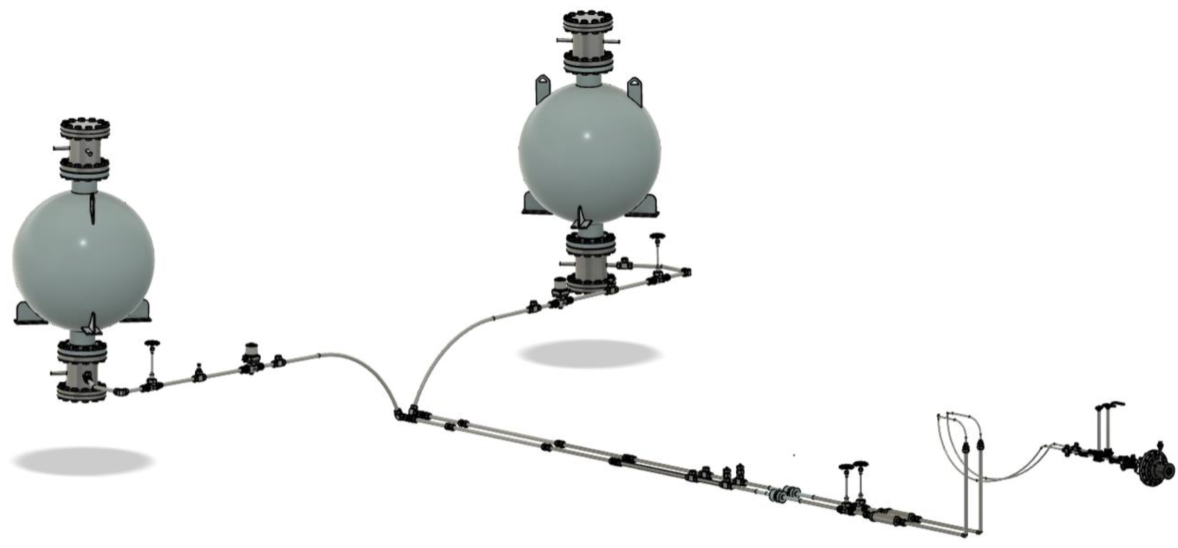
5]. In addition to the engine assembly, CROME’s propulsion system includes two identical propellant tanks and two symmetric feed lines responsible for storing and transporting the cryogenic propellants to the combustion chamber.
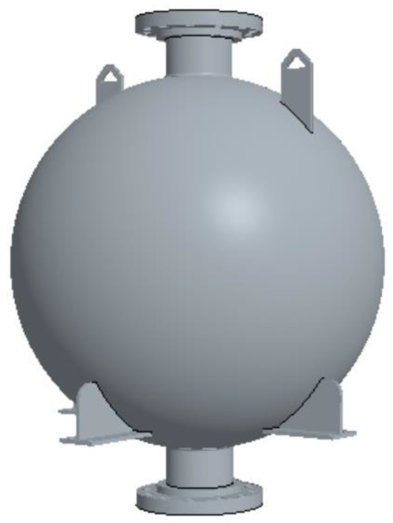
Figure 1 and
Figure 2 illustrate CROME’s full-system and cryogenic tank CAD models, respectively.
The propellant tanks store both
LOX and
LCH4 for hot-fire tests [
6], where both fluids are flown from the storage tanks to the combustion chamber and are ignited to evaluate engine performance.
LN2 is used in cold-flow testing [
7] to confirm the expected mass flow rates, temperatures, and pressures throughout the system. The tanks are tested at internal pressures of 200.0 psi and 400.0 psi, with the latter being the maximum allowable value for operation. At 200.0 psi,
LOX,
LCH4, and
LN2 exist at temperatures of −233.9 °F, −178.1 °F, and −265.0 °F, respectively, while at 400.0 psi, their temperatures are −208.1 °F, −145.0 °F, and −249.0 °F, respectively.
These extreme thermal conditions induce temperature gradients across the tank walls, resulting in severe thermal stresses that can compromise structural integrity [
8]. Although manufacturer data typically define safe operating pressure and temperature ranges, cryogenic systems are still vulnerable to failure during testing. In December 2008, a 935-gallon composite pressure vessel ruptured during cryogenic testing at NASA’s Kennedy Space Center [
9]. The incident caused severe injuries due to blast impact and cryogenic exposure, highlighting the importance of thoroughly validating the structural safety of cryogenic tanks during system testing.
Given the complex geometry and loading conditions involved, capturing stress values across a full cryogenic tank through manual calculations is a complex and time-consuming task. Therefore,
FEA simulations are widely used to capture stress distributions and identify maximum stress concentration areas in such models [
10]. These simulations allow engineers to assess mechanical performance under varying loads, evaluate design alternatives, and account for combined thermal and mechanical effects. The factor of safety (
FoS) is used to quantify structural reliability and is calculated by comparing the material’s yield or ultimate strength and the applied stress [
11]. Minimum
FoS values are commonly defined by codes depending on the application’s criticality and operating environment.
Star-CCM+ (Version 2402.0001) was the software of choice to compute the thermo-structural models due to its ability to perform coupled thermal and structural finite element simulations. The platform enables the simultaneous application of temperature and pressure loads, solving for thermal strain and the resulting stress distributions. Von Mises stress is computed from the stress tensor and serves as the key parameter to evaluate yielding behavior in ductile materials under multiaxial loading [
12].
2. Methodology
The thermo-structural model was developed in Star-CCM+ with the objective of quantifying the Von Mises stress (σVM) in cryogenic storage tanks operating under combined thermal and mechanical loading. This analysis focuses on the storage of LOX, LCH4, and LN2, which induce severe thermal gradients in the tank wall due to their extremely low temperatures.
While a conjugate heat transfer simulation would capture heat exchange between the cryogenic fluid, the tank wall, and ambient air, this study used a simplified but effective approach. Constant temperature values were applied to the tank’s inner and outer surfaces to define the thermal load. The inner wall matched the fluid’s saturation temperature at the operating pressure, and the outer wall was set to ambient temperature. This produced a thermal gradient across the wall, allowing Star-CCM+ to compute the Von Mises stress resulting from thermal and pressure loads. This method significantly reduces computational cost while capturing the essential structural effects of cryogenic loading under steady-state conditions.
This analysis utilized the
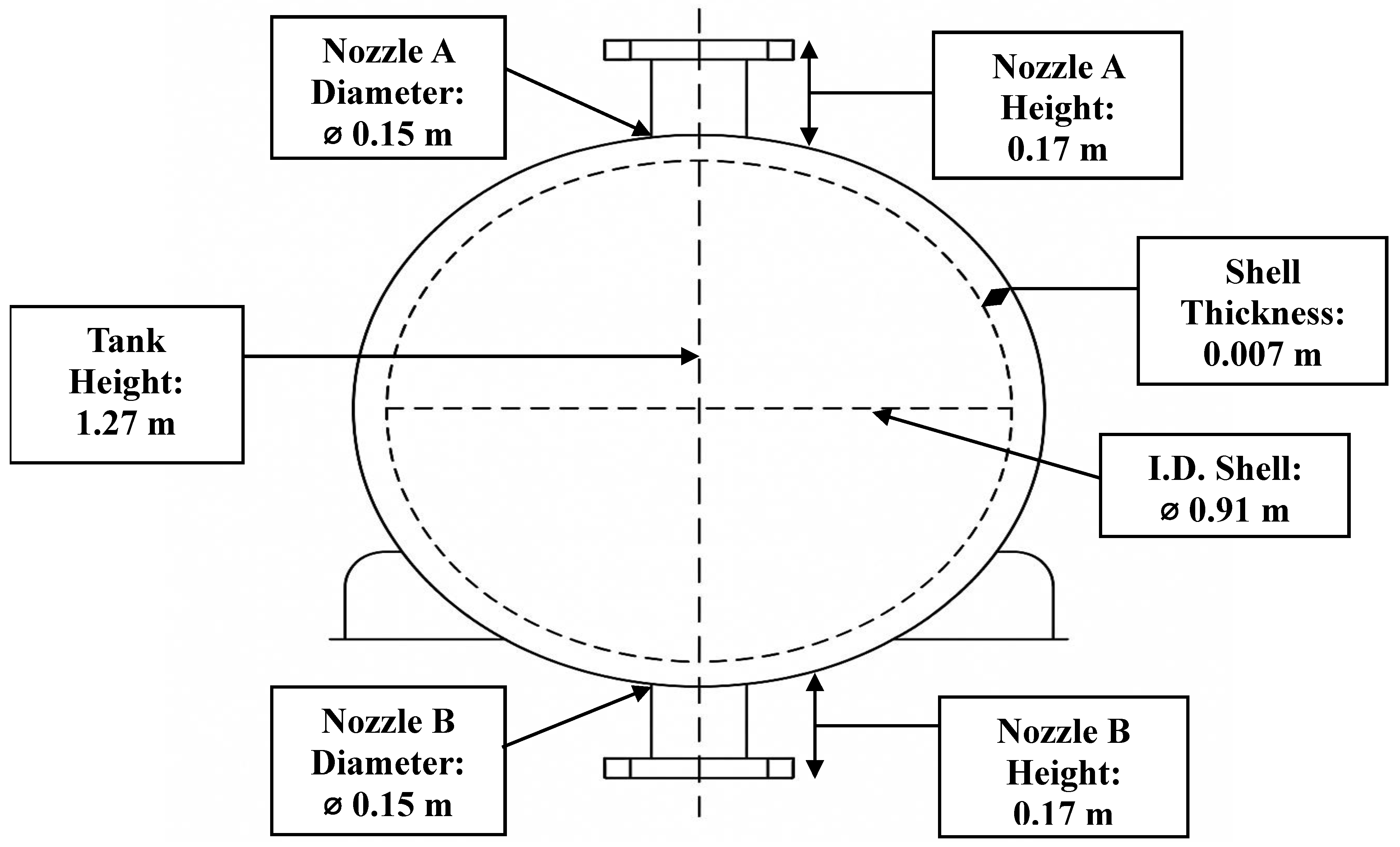
CAD model of the cryogenic tank from
Figure 2, with dimensions and features as detailed in
Figure 3. The setup, including boundary and initial conditions, is shown schematically in
Figure 4. The fixed-end boundary conditions at both flanged ends were applied as a simplified assumption to evaluate the structural response under constrained conditions, focusing on the effects of thermal and pressure loads.
Each case examines the tank subjected to internal pressure loads of 200.0 psi and 400.0 psi, representing the medium and maximum allowable operating conditions. Moreover, the saturation temperatures of the cryogenic fluids correspond to −233.9 °F (
LOX), −178.1 °F (
LCH4), and −265.0 °F (
LN2) at 200.0 psi and −208.1 °F (
LOX), −145.0 °F (
LCH4), and −249.0 °F (
LN2) at 400.0 psi and are applied to the inner tank wall. Moreover, the outer tank wall is assumed to be in thermal equilibrium with ambient air at a constant temperature of 80.0 °F. The temperature and pressure values utilized for each fluid case are shown in
Table 1.
The physics models used in Star-CCM+ to perform the thermo-structural analysis are condensed in
Table 2. The finite element solid energy and solid stress models [
13] were applied to solve the energy transport equation via the finite element approach. Also, the simulation considered isotropic linear and thermal expansions [
14] in the material of the tanks, stainless steel 316, as well as steady-state and three-dimensional conditions.
A total of six cases were analyzed, representing LN2, LOX, and LCH4 operating at 200.0 psi and 400.0 psi, respectively. For each case, the simulation computed the maximum Von Mises stress in the structure, which was then compared with the material’s ultimate strength (Sut) to evaluate the factor of safety (FoS) under the applied loading conditions.
A mesh independence study [
15] was carried out to evaluate the sensitivity of the thermo-structural results by examining how mesh refinement influenced the predicted factor of safety (FoS) and Von Mises stress. Although FoS served as the primary metric for evaluating mesh behavior, Von Mises stress was also monitored due to its complementary role in indicating structural reliability and its direct relation to FoS. Mesh base sizes of 1.0 m, 0.5 m, 0.1 m, 0.05 m, 0.01 m, and 0.005 m were tested, with all other meshing parameters such as surface remeshing, prism layers, and growth rates kept constant. In Star-CCM+, the mesh base size is a global, user-defined input that establishes the reference scale for generating surface and volume elements, thereby controlling overall mesh resolution. In this study, only the base size was varied, with smaller values producing finer meshes and higher element counts, enabling direct observation of FoS variation as a function of mesh resolution. The meshing models and solver configurations are detailed in
Table 3, and
Figure 5 presents the mesh distribution within the tank geometry.
3. Mesh Independence Study
A mesh independence study was conducted to validate the numerical convergence of the thermo-structural model, focusing specifically on the cryogenic tank filled with LN
2 at 400.0 psi. The objective was to determine whether further mesh refinement would significantly alter the computed factor of safety (FoS). Six simulations were performed using decreasing mesh base sizes ranging from 1.0 m to 0.005 m, while keeping all other meshing parameters constant, as shown in
Table 3.
In STAR-CCM+, the mesh base size is a user-defined global setting that controls how fine or coarse the mesh is throughout the model. It sets the base size used for the surface and volume elements, and most other mesh settings are adjusted automatically in proportion to it. Reducing the base size leads to a finer mesh with more elements, especially in complex regions. In this study, only the mesh base size was varied, ensuring that changes in the FoS were directly related to the mesh resolution. Von Mises stress was also tracked across all mesh levels, as it directly determines the FoS and reveals how critical stress regions evolve with refinement.
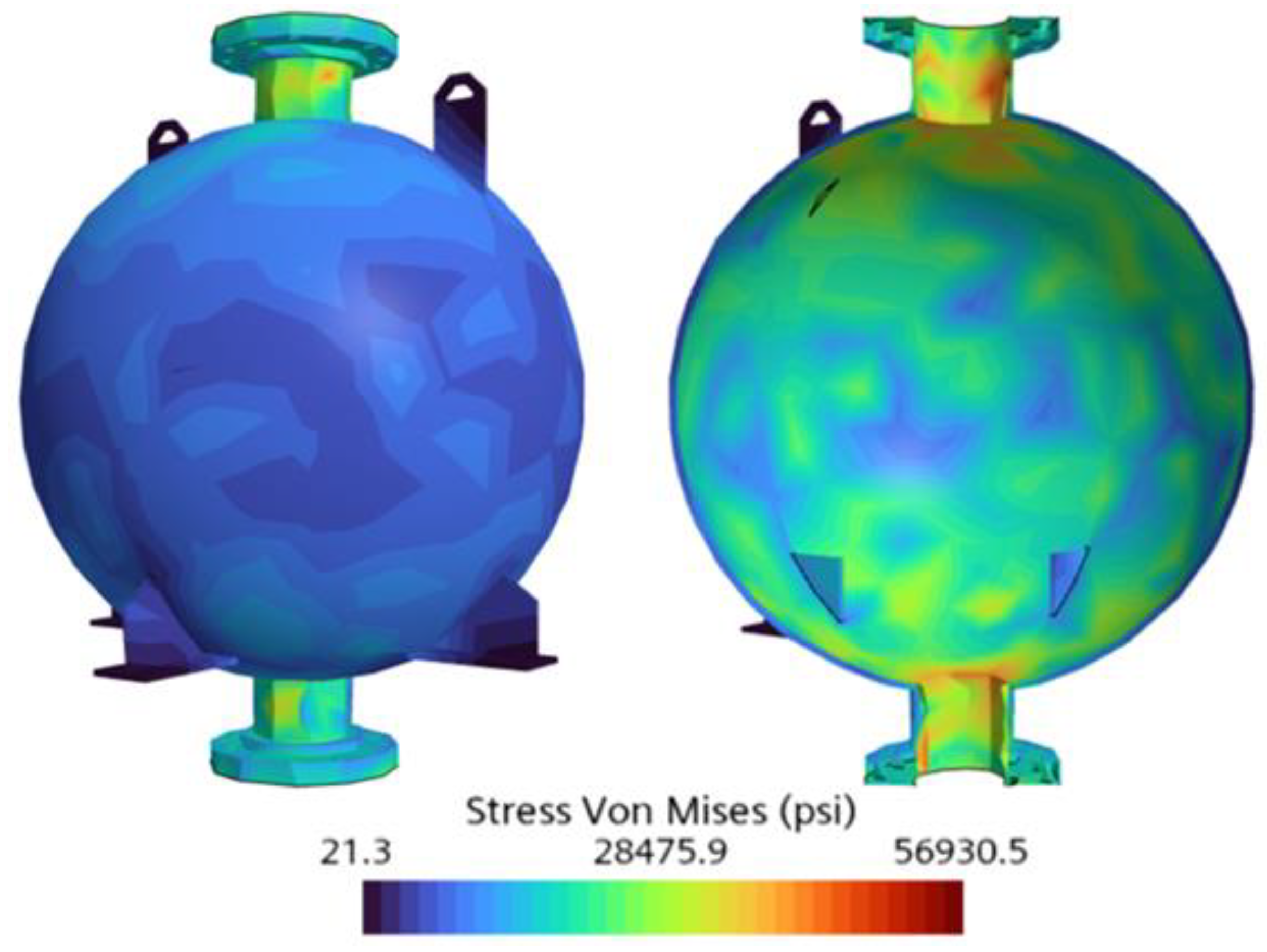
As shown in
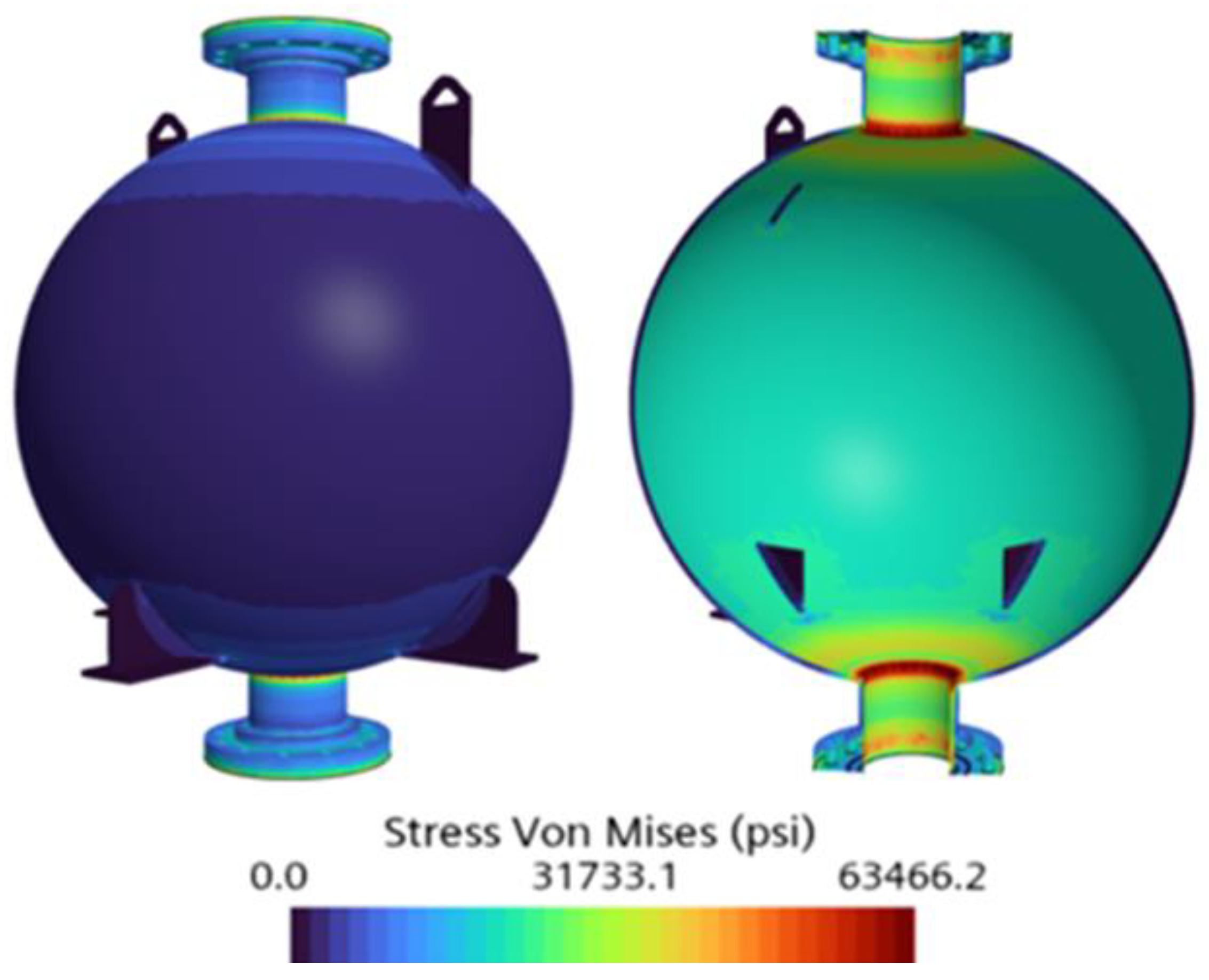
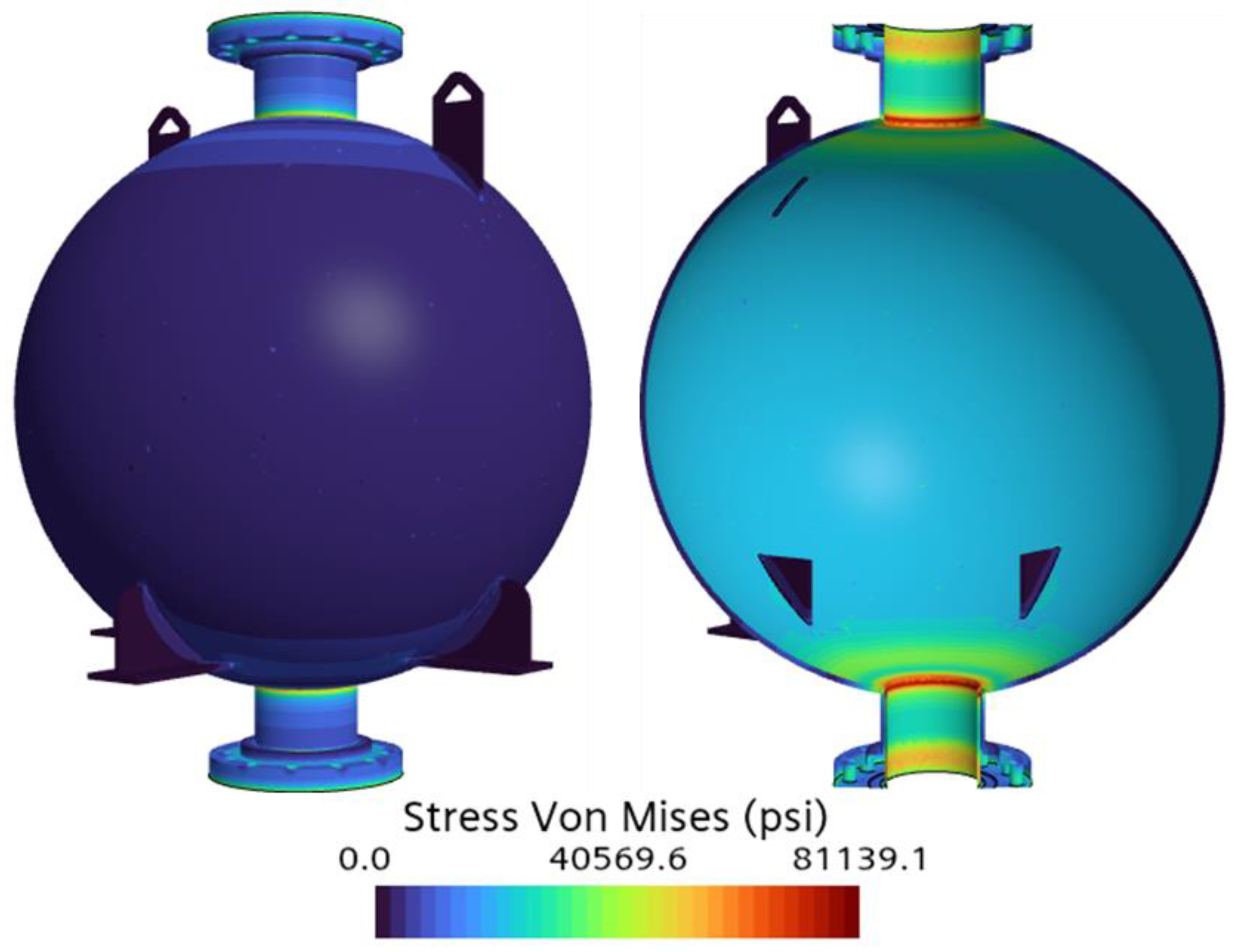
Table 4, a clear trend of decreasing FoS with increasing element count was observed, particularly in the early cases. Case 1 (base size 1.0 m, 12,412 elements) yielded a maximum Von Mises stress of 56,930.5 psi and the highest FoS of 2.9 among all the cases. Refinement to 0.5 m in Case 2 (23,827 elements) increased the maximum Von Mises stress to 61,080.5 psi and reduced the FoS to 2.7. In Case 3 (base size 0.1 m, 402,490 elements), the maximum Von Mises stress slightly increased to 63,466.2 psi, with the FoS decreasing to 2.6. Further refinement to 0.05 m in Case 4 (1,695,991 elements) raised the maximum Von Mises stress to 77,264.8 psi and significantly reduced the FoS to 2.1. Case 5 (0.01 m, 2,206,286 elements) showed an increased maximum Von Mises stress of 81,928.4 psi and an FoS of 2.0. Lastly, the mesh was further refined to 0.005 m (2,297,285 elements), resulting in a maximum Von Mises stress of 81,139.1 psi and an FoS of 2.0. The Von Mises stress contours for all mesh independence cases are shown in
Figure 6,
Figure 7,
Figure 8,
Figure 9,
Figure 10 and
Figure 11.
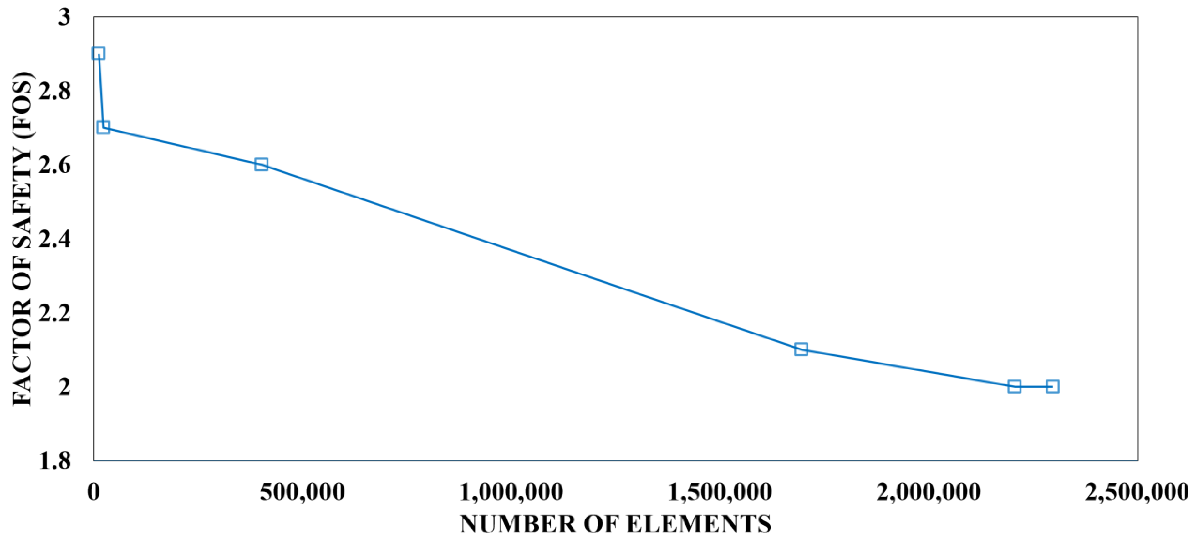
From Case 1 to Case 4, the mesh was refined by over 13,000%, resulting in a 35.7% increase in maximum Von Mises stress, which was consistent with expectations due to the improved resolution of stress gradients. Between Case 4 and Case 5, a 30.1% increase in element count led to only a 6.0% rise in stress, indicating diminishing stress variation with further refinement. From Case 5 to Case 6, the maximum Von Mises stress decreased slightly by 1.0%, despite an additional 4.1% refinement.
In terms of structural reliability, the factor of safety (FoS) decreased by 27.6% from Case 1 to Case 4, and by 4.8% from Case 4 to Case 5, with no change observed between the last two cases. Further mesh refinement beyond 0.005 m was not feasible due to virtual memory limitations and meshing instability. Nevertheless, these results suggest that FoS values began to stabilize after Case 4 and remained well above the failure threshold, defined as FoS = 1.0.
Figure 12 illustrates the FoS trend with increasing element count, showing signs of stabilization as the mesh nears 2 million elements. Although FoS served as the primary mesh independence metric, Von Mises stress was also analyzed due to its direct influence on FoS and its ability to highlight the consistency of high-stress regions. The trend indicated stress stabilization, suggesting convergence. It is important to note that each mesh case from 4 to 6 required significant computational resources, including extended initialization and simulation times. These simulations were performed using the highest available core count and the finest mesh resolution supported by our workstation. Given the observed trends, further refinement would have been likely to result in minimal changes. Thus, considering both the convergence behavior and computational limitations, the selected mesh (base size = 0.01 m) offers a well-balanced and reliable solution in terms of accuracy and efficiency.
4. Results
This section presents the results of the thermo-structural analysis conducted on the cryogenic propellant tanks, evaluating their structural response under combined thermal and mechanical loading. Simulations were performed for each of the three cryogenic fluids used in the CROME propulsion system—LN2, LOX, and LCH4—at operating pressures of 200.0 psi and 400.0 psi, representing the system’s nominal and maximum operational limits.
The primary objective was to analyze stress generation in the tanks due to thermal gradients and internal pressure and to assess their structural safety by quantifying the resulting factor of safety (FoS) in each case.
The analysis emphasizes the maximum Von Mises stress, which serves as the main criterion for evaluating material yielding under multiaxial loading. For each scenario, the maximum Von Mises stress was compared against the ultimate strength of stainless steel 316 to determine the FoS and evaluate the structural integrity of the tanks under steady-state cryogenic conditions. Additionally, the distribution and localization of stress concentrations, especially in geometrically sensitive areas such as the nozzle–shell junctions, were examined to gain further insight.
As mentioned in the previous section, a comprehensive mesh independence study was conducted to assess the sensitivity of the factor of safety (FoS) to mesh refinement. The results demonstrate that changes in stress and FoS diminished significantly beyond a base size of 0.01 m, indicating that the mesh was sufficiently refined to capture the dominant structural behavior. Based on this, a mesh with a 0.01 m base size and more than two million elements was selected for all thermo-structural simulations presented in this section.
Additionally, this section investigates the influence of fluid temperature and pressure on the tank’s structural performance. Notably, the contribution of thermal gradients to overall stress is analyzed across cases, as simulations with identical pressures but different fluids revealed varying stress responses due to differences in cryogenic temperatures. Results from pressure-only simulations are also discussed to enable a comprehensive evaluation of thermal stress and its role in the tank’s structural behavior.
Table 1 in the Methodology section summarizes the simulation conditions for each case. Detailed results for LN
2, LOX, and LCH
4 are presented in
Section 4.1,
Section 4.2 and
Section 4.3, respectively.
Section 4.4 provides an integrated discussion of the findings, highlighting the role of thermal loading and evaluating structural FoS across all operating conditions.
4.1. LN2 as the Fluid of Cryogenic Tank
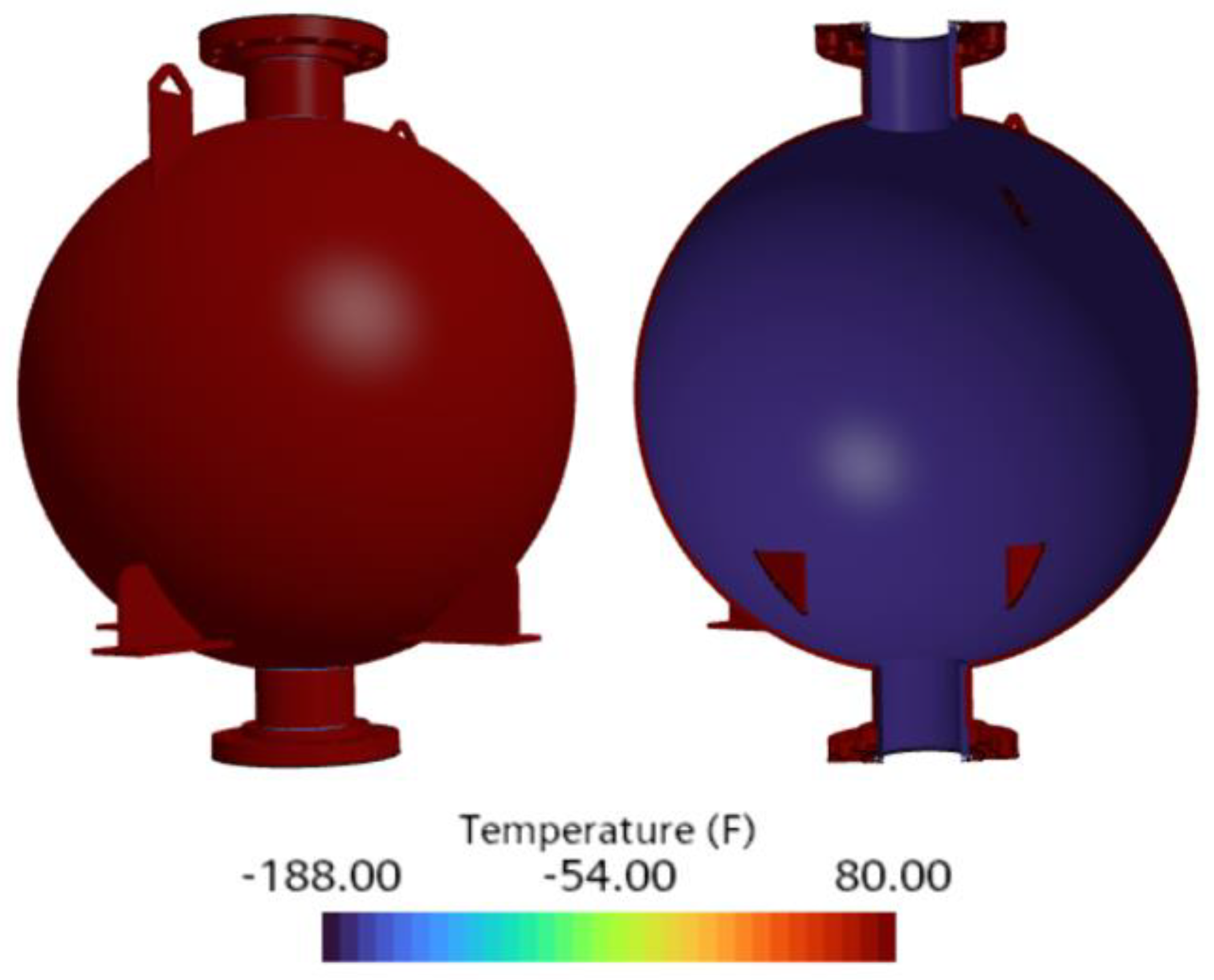
Liquid nitrogen (LN2) is used in cold flow testing of the CROME propulsion system to validate pressure, temperature, and mass flow parameters under non-reacting conditions. The current thermo-structural analysis evaluates two LN2 cases corresponding to tank operating pressures of 200.0 psi and 400.0 psi, with associated saturation temperatures of –265.0 °F and –249.0 °F, respectively.
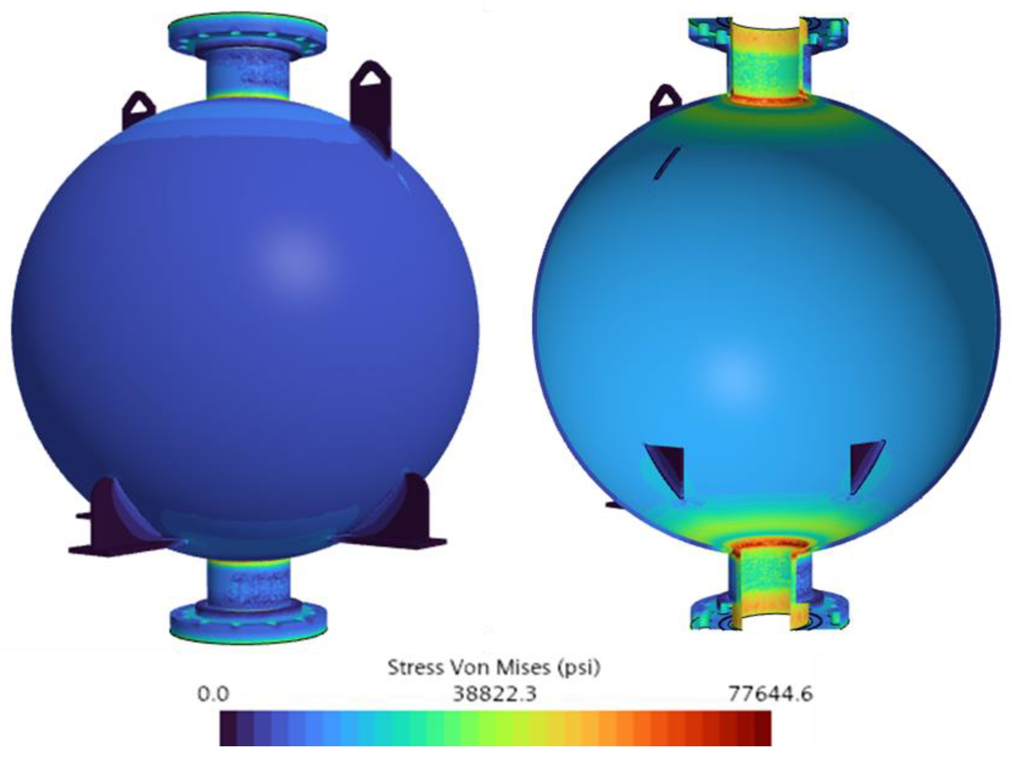
In Case 1 (200.0 psi, –265.0 °F), the simulation predicted a maximum Von Mises stress of 77,644.6 psi, concentrated at the junctions between the nozzle flanges and the tank shell. These regions exhibit geometric discontinuities where stress accumulation is expected. The flanges constrain radial deformation, creating high tensile stresses under internal pressure and thermal contraction. Meanwhile, the stress in the spherical tank remained nearly uniform at approximately 22,500.0 psi, indicating that elevated stress gradients resulted primarily from geometric features rather than uniform material loading.
Figure 13 shows the Von Mises stress contour for this case.
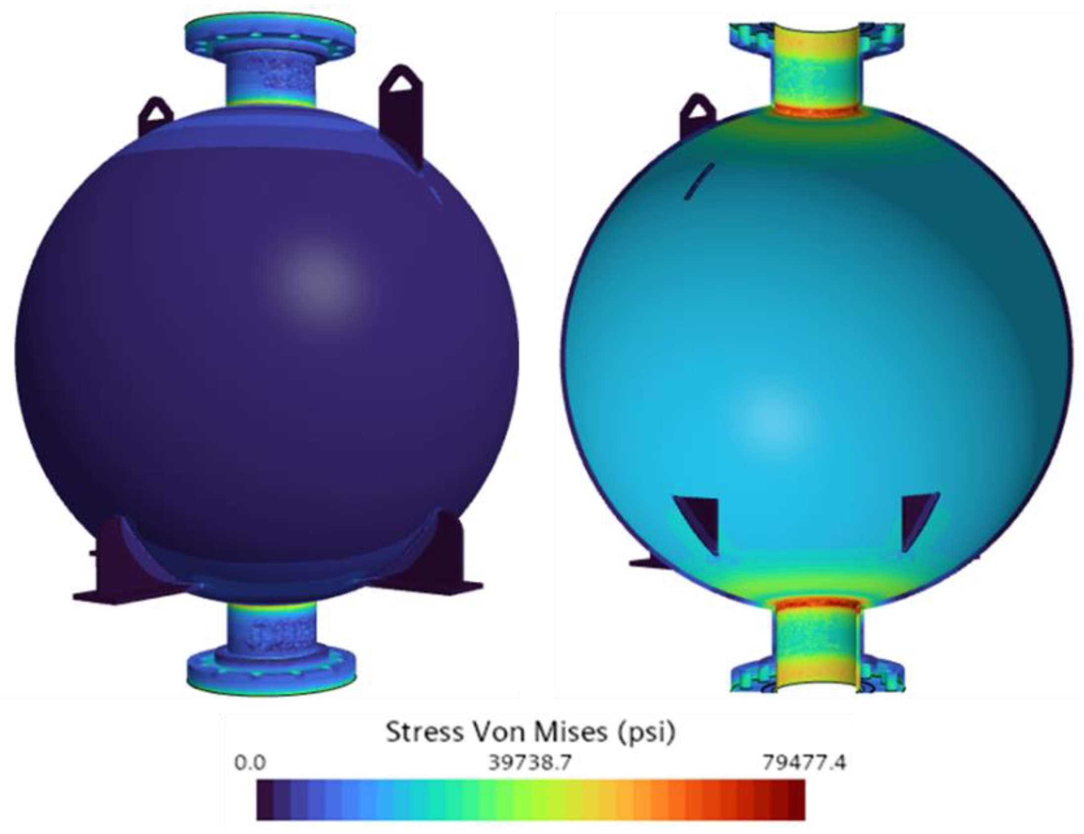
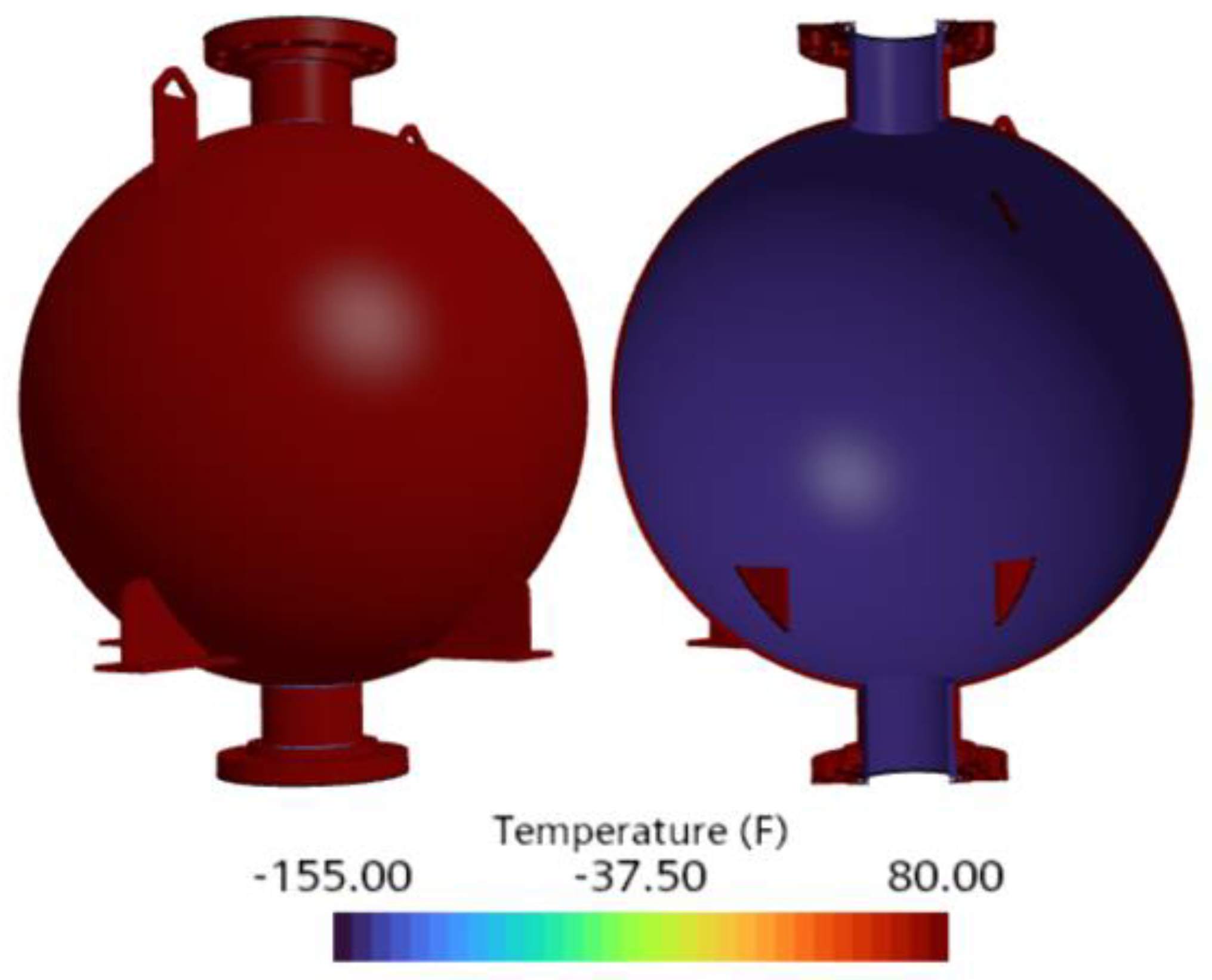
In Case 2 (400.0 psi, –249.0 °F), the maximum Von Mises stress increased moderately to 79,477.4 psi, as illustrated in
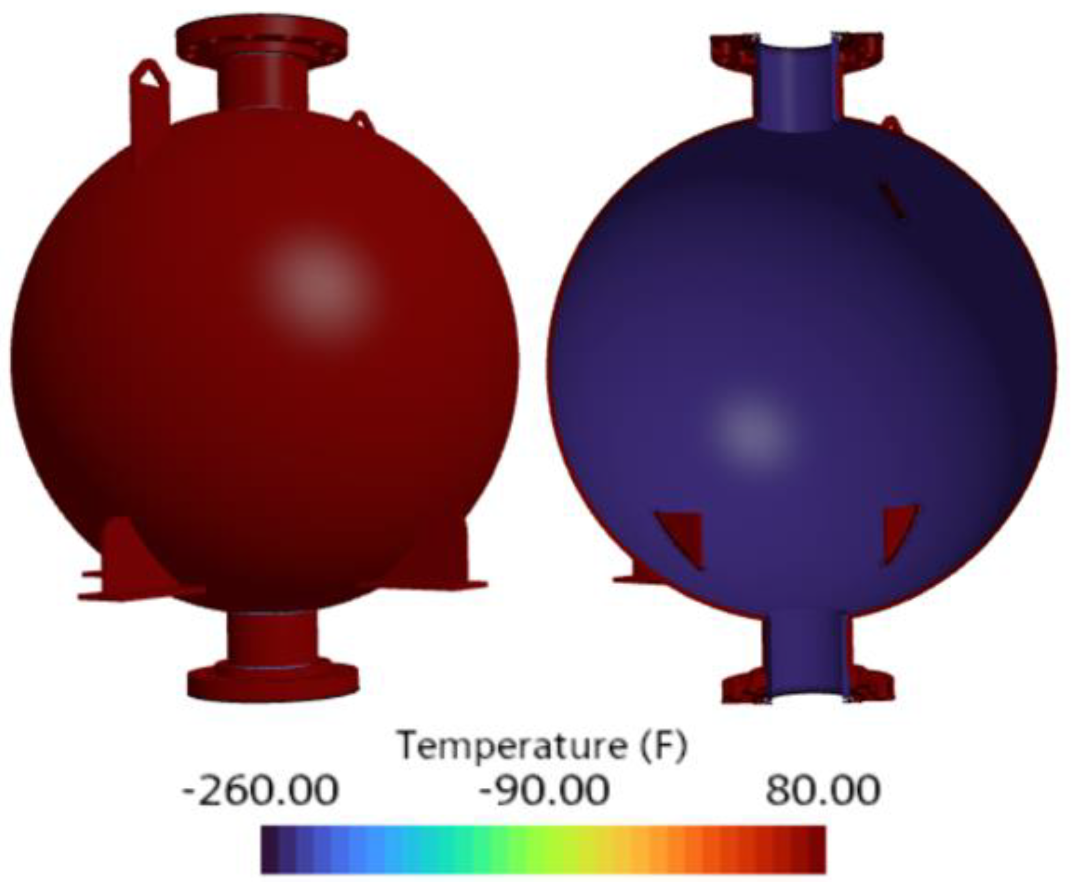
Figure 14. Although the internal pressure doubled, the corresponding stress increase was only about 2.3%. This is because the higher pressure raised the inner wall temperature, thereby reducing the thermal gradient across the tank wall, as shown in the static temperature contours in
Figure 15 and
Figure 16. While the outer wall temperature remained fixed at an ambient 80.0 °F, the inner wall temperature increased from –265.0 °F to –249.0 °F. As a result, the thermal gradient decreased from 345.0 °F to 329.0 °F, which reduced the thermal contraction.
Since thermal loading is the dominant source of stress in the tank, the reduced thermal gradient offset most of the additional stress expected from the pressure increase. This trend was also observed in the spherical section of the tank, where the stress increased from approximately 22,500.0 psi to 26,000.0 psi between Cases 1 and 2. These values remained well below the ultimate strength of stainless steel 316, while the localized stress concentrations at the junctions continued to dominate the structural response.
The factor of safety (FoS) for Cases 1 and 2 was 2.2 and 2.1, respectively, confirming structural integrity under both scenarios. Notably, the spherical portion of the tank exhibited significantly higher FoS values of approximately 7.5 and 6.3, respectively, due to its uniform stress distribution and low stress gradients.
Among the three cryogenic fluids examined, LN2 induced the most severe thermal loading due to its extremely low saturation temperatures. The results from these two cases underscore that thermal stress is the primary driver of Von Mises stress in the cryogenic tank, especially in regions with abrupt geometry or mechanical constraints.
4.2. LOX as the Fluid of Cryogenic Tank
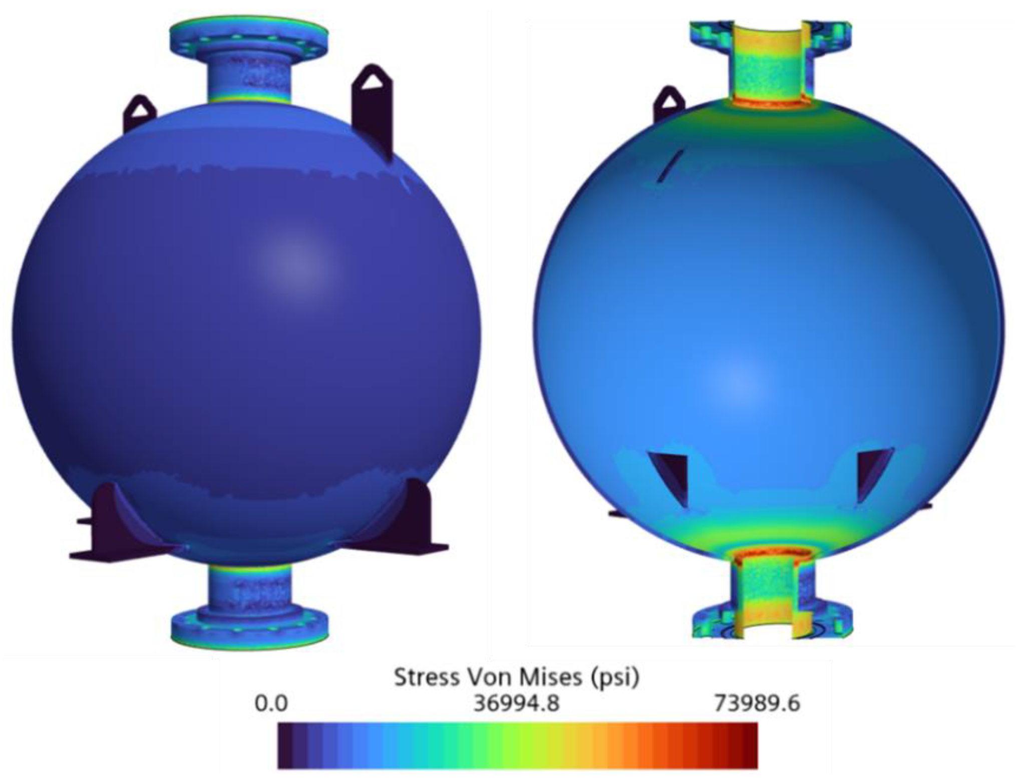
The thermo-structural behavior of the cryogenic tank storing LOX was investigated in Cases 3 and 4, which simulated operating pressures of 200 psi and 400 psi, respectively. The corresponding internal tank temperatures were −233.9 °F and −208.1 °F, representing LOX saturation temperatures at the given pressures.
In Case 3 (200.0 psi, −233.9 °F), the simulation predicted a maximum Von Mises stress of 73,989.6 psi, concentrated at the nozzle insertion region of the tank. As in previous cases, this area presented geometric discontinuities that restricted deformation and amplified localized stress. Meanwhile, the spherical body of the tank maintained a uniform stress distribution of approximately 20,000.0 psi, indicating that the elevated stress values were confined to the flange interface rather than spread throughout the tank structure.
Figure 17 illustrates the Von Mises stress distribution for this case.
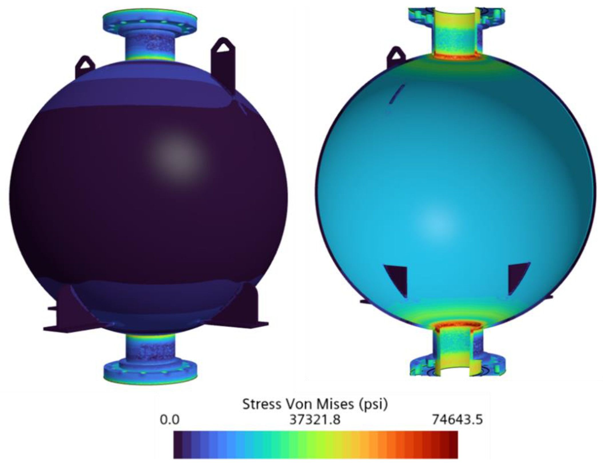
In Case 4 (400.0 psi, −208.1 °F), the maximum Von Mises stress increased slightly to 74,643.5 psi, as shown in
Figure 18. Despite doubling the pressure from Case 3, the resulting stress increase was only 0.9%, highlighting the dominant role of thermal loading over mechanical pressure. This minimal rise is attributable to the theoretical saturation temperature increase from −233.9 °F to −208.1 °F, which reduced the thermal gradient (T
sat-T
atm) from 313.9 °F to 288.1 °F and decreased the thermal contraction in the tank structure. A similar trend is evident in
Figure 19 and
Figure 20. The increase in applied pressure within the tank leads to a reduction in thermal concentrations, decreasing from 325 °F to 298 °F. The observed discrepancies in thermal gradients can be attributed to inherent differences between the theoretical and finite element analysis (FEA) approaches; however, these could be minimized through further refinement of computational parameters. Additionally, this reduced thermal gradient helped offset the added mechanical load, resulting in a minimal change in total stress.
Similar to the LN2 cases, nearly constant stress was observed in the spherical portion of the tank, with values moderately increasing from approximately 20,000.0 psi to 23,000.0 psi between Cases 3 and 4. These values remained below the ultimate strength of stainless steel 316, while the peak stresses near the nozzle junction continued to dominate the structural behavior.
The factor of safety (FoS) for Cases 3 and 4 was 2.2 and 2.0, respectively, confirming structural safety in both scenarios. Additionally, the spherical portion of the tank continued to exhibit higher FoS values of approximately 7.9 and 6.6, respectively, due to its smooth geometry and evenly distributed stresses.
Compared with LN2, LOX exhibits slightly lower thermal loads due to its higher saturation temperature and, consequently, produces lower Von Mises stress values. Furthermore, the results from these two cases reinforce that the highest Von Mises stresses remain concentrated in regions of abrupt geometry, where thermal and mechanical stresses are maximized. These results emphasize that, despite increases in mechanical pressure, high thermal gradients remain the dominant driver of stress in LOX storage within the cryogenic tank.
4.3. LCH4 as the Fluid of Cryogenic Tank
Cases 5 and 6 evaluated the thermo-structural response of the cryogenic tank storing LCH
4 at operating pressures of 200.0 psi and 400.0 psi, with corresponding saturation temperatures of −178.1 °F and −145.0 °F, respectively. As shown in
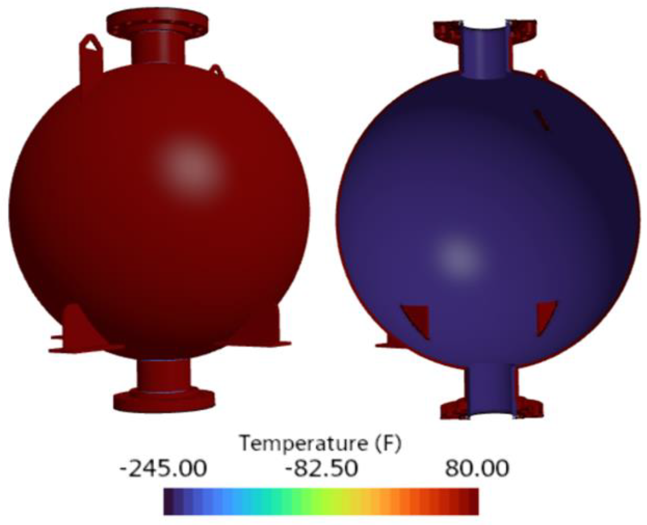
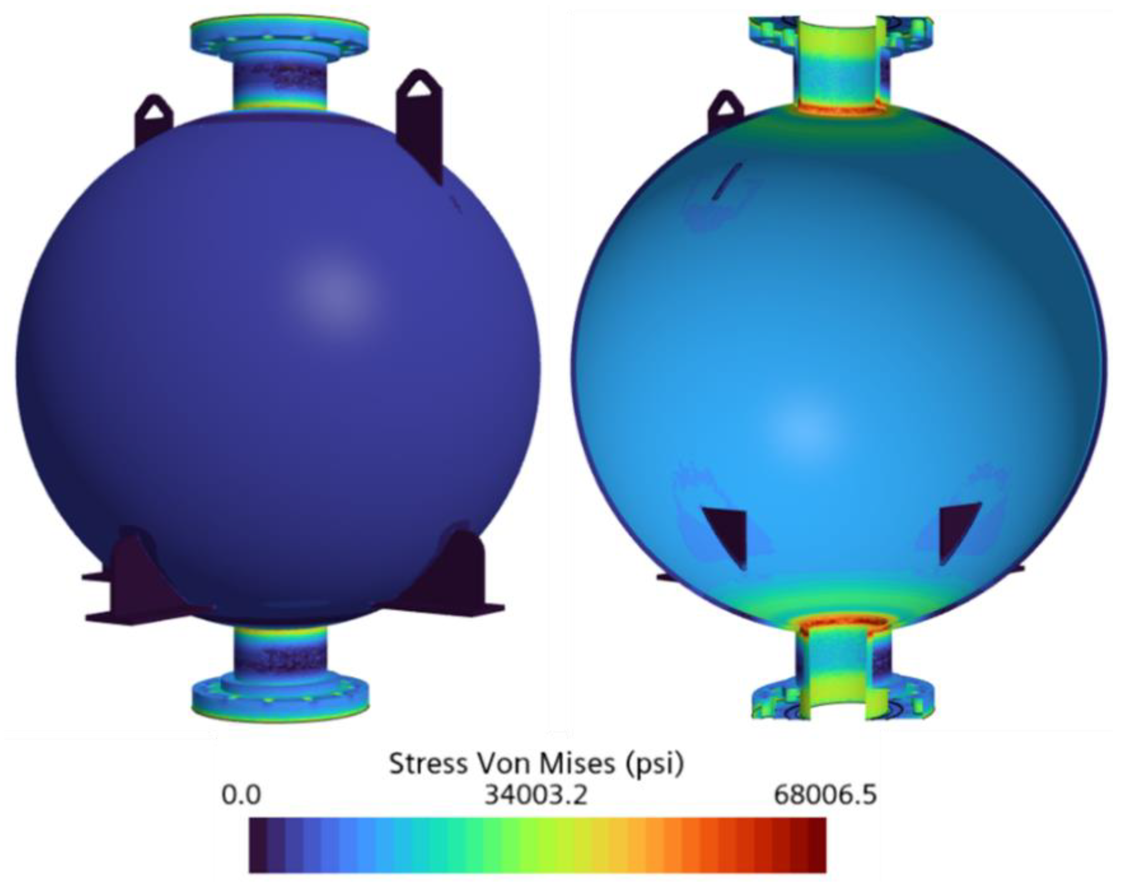
Figure 21 and
Figure 22, the predicted maximum Von Mises stresses were 67,567.5 psi for Case 5 and 68,006.5 psi for Case 6, representing the lowest stress magnitudes among all six cases.
This reduction in stress is attributable to the higher saturation temperatures of LCH4 compared with LN2 and LOX, which significantly reduced the thermal gradients across the tank wall and resulted in less thermal contraction. Although the applied pressure doubled from Case 5 to Case 6, the overall stress increase was minimal, rising by less than 1.0%. This further confirms that thermal effects, rather than pressure loading, continued to dominate the structural response in the cryogenic tank.
The stress distribution remained consistent with the previous cases, showing that the highest stress gradients were concentrated at the nozzle–shell junction, while the spherical portion of the tank maintained a nearly uniform stress level of approximately 19,000.0 psi. This uniformity confirms that the main body of the tank underwent minimal distortion, while higher stress magnitudes were confined to regions of abrupt geometry. The corresponding static temperature contours, shown in
Figure 23 and
Figure 24, illustrate reduced thermal gradients relative to the LN
2 and LOX cases.
The FoS values for Cases 5 and 6 were 2.1 and 2.0, respectively. These results confirm the tank’s structural integrity under both loading conditions and demonstrate that it remained well within safe operational limits. Furthermore, the spherical section of the tank continued to exhibit a significantly higher FoS of approximately 7.0 due to its favorable geometry and distributed loading.
Among the three cryogenic fluids analyzed, LCH4 imposes the mildest thermal stress due to its relatively high saturation temperatures. Results from Cases 5 and 6 further reinforce that thermal gradients are the primary drivers of elevated stress concentrations in the cryogenic tank structure.
4.4. Discussions and Findings
The thermo-structural behavior of the cryogenic tanks was investigated through six simulation cases that varied the stored fluid (LN
2, LOX, LCH
4) and the applied pressure (200.0 psi and 400.0 psi). As shown in
Table 5, results consistently indicated that the most influential factor in stress generation was the large thermal gradient across the tank wall, resulting from the extremely low saturation temperatures of the examined cryogenic fluids. This observation was quantitatively supported by the marginal increases in Von Mises stress when the pressure was doubled. For example, in the LN
2 cases, the stress increased by only 2.3% between 200.0 and 400.0 psi, and by less than 1.0% in the LOX and LCH
4 cases, despite a 100% increase in pressure. These findings confirm that thermally induced stress is the primary mechanism governing structural response under cryogenic conditions. This result aligns with experimental and numerical findings in the literature, where steep thermal gradients during chill-down or filling cycles produced the highest stress magnitudes in cryogenic tanks, even when pressure was negligible or vented [
16,
17,
18].
The maximum stress consistently occurred at the nozzle–shell junction, a region characterized by abrupt geometric discontinuities that acted as stress intensifiers. FEA simulations revealed localized peak Von Mises stress in this region for all six cases, while the spherical portion of the tank maintained uniform and significantly lower stress values, ranging from 19,000.0 psi to 23,000.0 psi. This observation is corroborated by various studies in structural mechanics, which show that geometrically constrained regions—especially nozzle insertions into curved vessels—experience elevated stress concentrations [
19,
20,
21]. The sensitivity of this region to local yielding underscores the importance of targeted design measures, such as fillets, stress-relief pads, or reinforcement collars, to mitigate failure risks [
22,
23].
To isolate the contribution of mechanical pressure to the overall stress field, pressure-only simulations were conducted on the cryogenic tank geometry, omitting thermal loads. The comparison revealed that the maximum Von Mises stress under pressure-only conditions was substantially lower than in the full thermo-structural cases. Specifically, the maximum Von Mises stress under 200.0 psi and 400.0 psi pressure loads alone was 8,049.2 psi and 16,193.5 psi, respectively. These values are listed in
Table 6 and correspond to factors of safety (FoS) of 10.4 and 5.2, respectively. This analysis further reinforces that thermal gradients are not only non-negligible but are the primary drivers of stress in cryogenic tank structures [
16,
24,
25].
Despite the high stress concentrations at the nozzle–shell junction, the tank maintained structural integrity across all simulated cases. The maximum Von Mises stress in this region remained below the ultimate strength of stainless steel 316 at cryogenic temperatures, with the lowest FoS of 2.0 observed in the LOX and LCH4 cases at 400.0 psi. This value satisfies conventional design criteria for structural safety and suggests that the cryogenic tanks are not expected to fail under these conservative mechanical and thermal loads.
Furthermore, stainless steel 316 retains exceptional mechanical properties under cryogenic conditions and is well known for its increased strength, high ductility, and excellent fracture toughness at temperatures near −300.0 °F. These characteristics make stainless steel 316 highly suitable for cryogenic applications, where localized plastic deformation is expected due to thermal contraction effects [
26,
27]. As a result, limited yielding at the nozzle–shell junction should be interpreted as a predictable and manageable phenomenon rather than an indication of design failure.
5. Summary
This study presents a comprehensive thermo-structural analysis of cryogenic propellant tanks designed to store LN2, LOX, and LCH4 under operating pressures of 200 psi and 400 psi. Finite element analysis (FEA) simulations were conducted using Star-CCM+ to evaluate the structural performance of the tanks under combined thermal and internal pressure loads. Thermal boundary conditions were defined based on the saturation temperatures of the respective fluids at each pressure, with LN2 exhibiting the most extreme thermal gradients due to its lower boiling point.
Results from all six cases revealed that thermal gradients were the primary contributors to Von Mises stress, while internal pressure played a secondary role. The maximum stress concentration consistently occurred at the nozzle–shell junction, where abrupt geometric transitions amplified the stress magnitude. In contrast, the spherical section of the tank demonstrated uniform and significantly lower stress levels. Despite these localized concentrations, all simulated cases achieved a minimum factor of safety (FoS) of 2.0, confirming the structural integrity of the tanks under the analyzed thermal and mechanical loading conditions.
The behavior of stainless steel 316 at cryogenic temperatures was also considered, and the results support the conclusion that the tanks will remain structurally sound during steady-state operation. However, the recurring stress concentration at the nozzle–shell junction indicates that this region should be reinforced in future designs to mitigate localized yielding and extend structural durability.
The mesh independence study further validated the credibility of the simulation results. Although additional refinement was limited by computational resources, the diminishing variation in FoS with increasing element count demonstrated convergence and supports confidence in the final reported FoS for each case.
In conclusion, this study confirms the structural safety of the cryogenic tanks used in the CROME propulsion system under combined thermal and pressure loads. Even under severe thermal gradients, the tanks remain within safe operating margins. However, critical regions such as the nozzle–shell junction should be reinforced in future designs to enhance resilience in demanding cryogenic environments.
Author Contributions
Conceptualization, S.O., C.L.R.Z., M.A.H. and A.C.; Methodology, S.O., C.L.R.Z. and M.A.H.; Software, A.C.; Validation, S.O., C.L.R.Z. and M.A.H.; Formal analysis, S.O., C.L.R.Z. and M.A.H.; Investigation, S.O., C.L.R.Z. and M.A.H.; Resources, A.C.; Data curation, S.O., C.L.R.Z. and M.A.H.; Writing—original draft, S.O., C.L.R.Z. and M.A.H.; Supervision, M.A.H. and A.C.; Project administration, A.C.; Funding acquisition, A.C. All authors have read and agreed to the published version of the manuscript.
Funding
This material is based on research sponsored by the Air Force Research Laboratory under agreement number FA8650-20-2-5700. The U.S. government is authorized to reproduce and distribute reprints for governmental purposes notwithstanding any copyright notation thereon.
Data Availability Statement
The data presented in this study are available on request from the corresponding author. The data are not publicly available due to the ITAR and/or agency’s policies.
Acknowledgments
The authors would like to acknowledge the UTEP Aerospace Center for the tools and guidance that made this analysis possible and the rest of the Aerospace Center lander team for their knowledge and support. Additionally, the authors would like to thank project mentors and faculty supervisors for their tremendous assistance in learning to use Star-CCM+, choosing accurate models and parameters for thermo-structural analysis, and interpreting model results.
Conflicts of Interest
The authors declare no conflict of interest.
Disclaimer
The views and conclusions contained herein are those of the authors and should not be interpreted as necessarily representing the official policies or endorsements, either expressed or implied, of the Air Force Research Laboratory or the U.S. Government.
Nomenclature
| Ac | Cross-sectional area |
| CFD | Computational fluid dynamics |
| FEA | Finite element analysis |
| FoS | Factor of safety |
| lbf | Pound force |
| LCH4 | Liquid methane |
| LN2 | Liquid nitrogen |
| LOX | Liquid oxygen |
| σth | Thermal stress |
| σVM | Von Mises stress |
| σVM,max | Maximum Von Mises stress |
| Syt | Material yield strength |
| Sut | Material ultimate strength |
References
- Hulbert, E.; Morehead, R.; Melcher, J.C.; Atwell, M. Integrated pressure-fed liquid oxygen/methane propulsion systems–Morpheus experience, MARE, and future applications. In Proceedings of the AIAA/SAE/ASEE Joint Propulsion Conference, Salt Lake City, UT, USA, 25–27 July 2016. [Google Scholar]
- Mane, S. In-Situ Resource Utilization for Moon & Mars System; Department of Research & Development, Astroex Research Association: Deoria, India, 2022. [Google Scholar]
- NASA. In-Situ Resource Utilization (ISRU) Capability Roadmap Final Report; NASA: Washington, DC, USA, 2005.
- Herrera, M. The Design and Testing of a 500 lbf Liquid Oxygen/Liquid Methane Engine. Master’s Thesis, The University of Texas at El Paso, El Paso, TX, USA, 2019. [Google Scholar]
- Wu, C.; Antol, J.; Watson, J.J.; Saucillo, R.J.; North, D.D.; Mazanek, D.D. Lunar Lander Structural Design Studies at NASA Langley; American Institute of Aeronautics and Astronautics: Reston, VA, USA, 2007. [Google Scholar]
- Marshall, W.M.; Kleinhenz, J.E. Hot-Fire Testing of 100 lbf LOX/LCH4 Reaction Control Engine at Altitude Conditions; NASA Technical Reports Server; NASA: Washington, DC, USA, 2010.
- Kenny, R.J.; Moser, M.D.; Hulka, J.; Jones, G. Cold flow testing for liquid propellant rocket injector scaling and throttling (AIAA Paper 2006-4705). In Proceedings of the 42nd AIAA/ASME/SAE/ASEE Joint Propulsion Conference, Sacramento, CA, USA, 9–12 July 2006. [Google Scholar]
- Stephens, C.A.; Hanna, G.J. Thermal Modeling and Analysis of a Cryogenic Tank Design Exposed to Extreme Heating Profiles; Prepared for NASA Dryden Flight Research Facility, Edwards, CA; NASA Dryden Flight Research Facility: Edwards, CA, USA, 1991.
- NASA. Cryogenic Tank Rupture Mishap (Lesson No. 4976); NASA Lessons Learned Information System: Washington, DC, USA, 2011.
- Sadanandam, P.; Ramesh, U.; Tamerat, S. Design and analysis of pressure vessel using finite element method. Int. J. Latest Technol. Eng. Manag. Appl. Sci. 2017, 6, 1–3. [Google Scholar]
- Shrivastava, A. Plastics part design and application. In Introduction to Plastics Engineering; Elsevier: Amsterdam, The Netherlands, 2018; pp. 179–205. [Google Scholar]
- Jong, I.-C.; Springer, W. Teaching von Mises stress: From principal axes to nonprincipal axes. In Proceedings of the 2009 Annual Conference & Exposition, Austin, TX, USA, 14–17 June 2009; American Society for Engineering Education: Washington, DC, USA, 2009. [Google Scholar]
- Sitek, M.; Bergeron, A.; Bojanowski, C.; Yu, Y.; Licht, J. Involute Working Group–Development and Validation of the Finite Element Models of the Cheverton-Kelley Experiments (ANL/RTR/TM-20/15); Argonne National Laboratory: Lemont, IL, USA, 2020. [Google Scholar]
- Bower, A.F. Applied Mechanics of Solids, 1st ed.; CRC Press: Boca Raton, FL, USA, 2009. [Google Scholar] [CrossRef]
- Sadrehaghighi, I. Mesh Sensitivity & Mesh Independence Study; CFD Open Series: Annapolis, MD, USA, 2021; p. 56. [Google Scholar] [CrossRef]
- Zhu, K.; Li, Y.; Ma, Y.; Wang, L.; Xie, F.; Wang, J. Experimental study on cool down characteristics and thermal stress of cryogenic tank during LN2 filling process. Appl. Therm. Eng. 2017, 130, 251–260. [Google Scholar] [CrossRef]
- Baker, J.M. Preliminary Thermal Stress Analysis of a High-Pressure Cryogenic Storage Tank (SE-2003-06-0043-SSC); NASA Technical Reports Server; NASA: Washington, DC, USA, 2003.
- Murugan, S.; Starvin, M.S.; Muruga Dhas, K. Thermo structural analysis of high pressure cryogenic tank. Int. J. Eng. Res. Technol. (IJERT) 2013, 2, 1730–1738. [Google Scholar]
- Bozkurt, M.; Nash, D. Stress concentration factor based design curves for cylinder-cylinder connections in pressure vessels. Eur. Mech. Sci. 2023, 7, 268–277. [Google Scholar] [CrossRef]
- Bahadur, R.; Mittal, V.K.; Angra, S. Stress analysis of pressure vessel nozzle using FEA. Int. J. Eng. Res. Technol. (IJERT) 2018, 6, 1–6. [Google Scholar]
- Qadir, M.A.; Redekop, D. SCF analysis of a pressurized vessel–nozzle intersection with wall thinning damage. Int. J. Press. Vessel. Pip. 2009, 86, 541–549. [Google Scholar] [CrossRef]
- Bozkurt, M.; Nash, D. Stress linearization application of oblique nozzles with welded pad reinforcement in cylindrical pressure vessels. Proc. Inst. Mech. Eng. Part C J. Mech. Eng. Sci. 2023, 238, 1642–1654. [Google Scholar] [CrossRef]
- Denduluri, A.T.; Vuranruj Dnuna, S.; Prasada, H.C.; Kuncha, S.C.; Rapeta, S.R. Design and analysis of reinforcement pad at nozzle junction on pressure vessel. In Proceedings of the 2nd Indian International Conference on Industrial Engineering and Operations Management, Warangal, Telangana, India, 16–18 August 2022; IEOM Society International: Southfield, MI, USA, 2022. [Google Scholar]
- Ma, Y.; Zhu, K.; Li, Y.; Xie, F. Numerical investigation on chill-down and thermal stress characteristics of a LH2 tank during ground filling. Int. J. Hydrogen Energy 2020, 45, 25344–25356. [Google Scholar] [CrossRef]
- NASA. Thermocryogenic Buckling and Stress Analyses of a Partially Filled Cryogenic Tank Subjected to Cylindrical Strip Heating. 1994. Available online: https://ntrs.nasa.gov/api/citations/19950011002/downloads/19950011002.pdf (accessed on 13 May 2025).
- Li, X.; Wei, Z.; Wang, X.; Yang, L.; Hao, X.; Wang, M.; Guo, M.; Guo, J. Effect of cryogenic temperatures on the mechanical behavior and deformation mechanism of AISI 316H stainless steel. J. Mater. Res. Technol. 2023, 22, 3375–3386. [Google Scholar] [CrossRef]
- Fernández-Pisón, P.; Rodríguez-Martínez, J.A.; García-Tabarés, E.; Avilés-Santillana, I.; Sgobba, S. Flow and fracture of austenitic stainless steels at cryogenic temperatures. Eng. Fract. Mech. 2021, 258, 108042. [Google Scholar] [CrossRef]
Figure 1.
CROME full-system CAD model.
Figure 1.
CROME full-system CAD model.
Figure 2.
Cryogenic tank CAD model.
Figure 2.
Cryogenic tank CAD model.
Figure 3.
Geometric configuration of the cryogenic tank.
Figure 3.
Geometric configuration of the cryogenic tank.
Figure 4.
Thermo-structural model boundary and initial conditions.
Figure 4.
Thermo-structural model boundary and initial conditions.
Figure 5.
3-D mesh image of the cryogenic tank.
Figure 5.
3-D mesh image of the cryogenic tank.
Figure 6.
(LN2) Case 1. Mesh Independence Study—Von Mises stress gradient.
Figure 6.
(LN2) Case 1. Mesh Independence Study—Von Mises stress gradient.
Figure 7.
(LN2) Case 2. Mesh Independence Study—Von Mises stress gradient.
Figure 7.
(LN2) Case 2. Mesh Independence Study—Von Mises stress gradient.
Figure 8.
(LN2) Case 3. Mesh Independence Study—Von Mises stress gradient.
Figure 8.
(LN2) Case 3. Mesh Independence Study—Von Mises stress gradient.
Figure 9.
(LN2) Case 4. Mesh Independence Study—Von Mises stress gradient.
Figure 9.
(LN2) Case 4. Mesh Independence Study—Von Mises stress gradient.
Figure 10.
(LN2) Case 5. Mesh Independence Study—Von Mises stress gradient.
Figure 10.
(LN2) Case 5. Mesh Independence Study—Von Mises stress gradient.
Figure 11.
(LN2) Case 6. Mesh Independence Study—Von Mises stress gradient.
Figure 11.
(LN2) Case 6. Mesh Independence Study—Von Mises stress gradient.
Figure 12.
Mesh Independence Study: Factor of Safety vs. Number of Elements.
Figure 12.
Mesh Independence Study: Factor of Safety vs. Number of Elements.
Figure 13.
(LN2) Cryogenic tank Von Mises stress gradient at 200.0 psi.
Figure 13.
(LN2) Cryogenic tank Von Mises stress gradient at 200.0 psi.
Figure 14.
(LN2) Cryogenic tank Von Mises stress gradient at 400.0 psi.
Figure 14.
(LN2) Cryogenic tank Von Mises stress gradient at 400.0 psi.
Figure 15.
(LN2) Cryogenic tank temperature gradient at 200.0 psi.
Figure 15.
(LN2) Cryogenic tank temperature gradient at 200.0 psi.
Figure 16.
(LN2) Cryogenic tank temperature gradient at 400.0 psi.
Figure 16.
(LN2) Cryogenic tank temperature gradient at 400.0 psi.
Figure 17.
(LOX) Cryogenic tank Von Mises stress gradient at 200.0 psi.
Figure 17.
(LOX) Cryogenic tank Von Mises stress gradient at 200.0 psi.
Figure 18.
(LOX) Cryogenic tank Von Mises stress gradient at 400.0 psi.
Figure 18.
(LOX) Cryogenic tank Von Mises stress gradient at 400.0 psi.
Figure 19.
(LOX) Cryogenic tank temperature gradient at 200.0 psi.
Figure 19.
(LOX) Cryogenic tank temperature gradient at 200.0 psi.
Figure 20.
(LOX) Cryogenic tank temperature gradient at 400.0 psi.
Figure 20.
(LOX) Cryogenic tank temperature gradient at 400.0 psi.
Figure 21.
(LCH4) Cryogenic tank Von Mises stress gradient at 200.0 psi.
Figure 21.
(LCH4) Cryogenic tank Von Mises stress gradient at 200.0 psi.
Figure 22.
(LCH4) Cryogenic tank Von Mises stress gradient at 400.0 psi.
Figure 22.
(LCH4) Cryogenic tank Von Mises stress gradient at 400.0 psi.
Figure 23.
(LCH4) Cryogenic tank temperature gradient at 200.0 psi.
Figure 23.
(LCH4) Cryogenic tank temperature gradient at 200.0 psi.
Figure 24.
(LCH4) Cryogenic tank temperature gradient at 400.0 psi.
Figure 24.
(LCH4) Cryogenic tank temperature gradient at 400.0 psi.
Table 1.
Thermo-structural analysis cases for LN2, LOX, and LCH4.
Table 1.
Thermo-structural analysis cases for LN2, LOX, and LCH4.
| Fluid | Case # | Pressure (psi) | Temperature (°F) |
|---|
| LN2 | 1 | 200.0 | −265.0 |
| 2 | 400.0 | −249.0 |
| LOX | 3 | 200.0 | −233.9 |
| 4 | 400.0 | −208.1 |
| LCH4 | 5 | 200.0 | −178.1 |
| 6 | 400.0 | −145.0 |
Table 2.
Physics models, and the boundary and initial conditions for the cryogenic tank thermo-structural model.
Table 2.
Physics models, and the boundary and initial conditions for the cryogenic tank thermo-structural model.
| Physics Models | Steady Solid Three-dimensional Finite element solid energy Solid stress Gravity Solution interpolation Material law models Isotropic linear elasticity Isotropic thermal expansion Linear elasticity Thermal expansion
|
| Boundary/Initial Conditions | Tank temperature: −265.3, −249.1 °F Tank pressure: 200.0 psi, 400.0 psi Gravity: −9.8 m/s2
|
Table 3.
Mesh settings for the cryogenic tank thermo-structural model.
Table 3.
Mesh settings for the cryogenic tank thermo-structural model.
| Meshers | Tetrahedral mesher Surface remesher Automatic surface repair Geometric sensitivity Thin mesher
|
| Settings | |
Table 4.
Results of the Mesh Independence Study for LN2 at 400.0 psi.
Table 4.
Results of the Mesh Independence Study for LN2 at 400.0 psi.
| Case | Mesh Base Size (m) | Number of Elements | σVM, max (psi) | Sut (SS 316)
(psi) | FoS |
|---|
| 1 | 1.0 | 12,412.0 | 56,930.5 | 165,246.1 psi | 2.9 |
| 2 | 0.5 | 23,827.0 | 61,080.5 | 165,246.1 psi | 2.7 |
| 3 | 0.1 | 402,490.0 | 63,466.2 | 165,246.1 psi | 2.6 |
| 4 | 0.05 | 1,695,991.0 | 77,264.8 | 165,246.1 psi | 2.1 |
| 5 | 0.01 | 2,206,286.0 | 81,928.4 | 165,246.1 psi | 2.0 |
| 6 | 0.005 | 2,297,285.0 | 81,139.1 | 165,246.1 psi | 2.0 |
Table 5.
Results for cryogenic tank thermo-structural model.
Table 5.
Results for cryogenic tank thermo-structural model.
| Fluid | Case | σVM, max (psi) | Sut (SS 316) (psi) | FoS |
|---|
| LN2 | 1 | 77,644.6 | 169,712.6 | 2.2 |
| 2 | 79,477.4 | 165,246.1 | 2.1 |
| LOX | 3 | 73,989.6 | 160,092.5 | 2.2 |
| 4 | 74,643.5 | 152,628.9 | 2.0 |
| LCH4 | 5 | 67,567.5 | 143,950.4 | 2.1 |
| 6 | 68,006.5 | 134,375.0 | 2.0 |
Table 6.
Von Mises stress under pressure loading.
Table 6.
Von Mises stress under pressure loading.
| Pressure (psi) | σVM, max (psi) | Sut (SS 316) (psi) | FoS |
|---|
| 200 | 8049.2 | 84,100.0 | 10.4 |
| 400 | 16,193.5 | 84,100.0 | 5.2 |
| Disclaimer/Publisher’s Note: The statements, opinions and data contained in all publications are solely those of the individual author(s) and contributor(s) and not of MDPI and/or the editor(s). MDPI and/or the editor(s) disclaim responsibility for any injury to people or property resulting from any ideas, methods, instructions or products referred to in the content. |
© 2025 by the authors. Licensee MDPI, Basel, Switzerland. This article is an open access article distributed under the terms and conditions of the Creative Commons Attribution (CC BY) license (https://creativecommons.org/licenses/by/4.0/).


