Article

Simulation Analysis and Experimental Verification of the Transport Characteristics of a High-Volume CubeSat Storage Device

1
School of Mechatronics Engineering, Harbin Institute of Technology, Harbin 150080, China
2
Harbin Space Star Data System Technology Co., Ltd., Harbin 150080, China
*
Authors to whom correspondence should be addressed.
Aerospace 2025, 12(6), 466; https://doi.org/10.3390/aerospace12060466
Submission received: 28 March 2025 / Revised: 22 May 2025 / Accepted: 23 May 2025 / Published: 25 May 2025
(This article belongs to the Special Issue Small Satellite Missions)

Abstract

:
To enhance the efficiency and extent of space resource development and utilization, this paper proposes a device designed for large-scale storage and transport of multi-species CubeSats, characterized by its high storage density and efficient transport capabilities. This paper comprehensively describes the structural composition and operational principles of this storage and transport system. Using dynamic simulation analysis, this paper studies the deployment mechanism of CubeSats within the push device and identifies the movement rules of the CubeSats during the deployment process. Simulation results show that under microgravity conditions, the average linear displacement speed of CubeSats reaches 32.8 mm/s during the pushing process. A prototype of the storage device was developed and tested for scenarios where the CubeSat’s initial position is aligned or misaligned relative to the transport pallet. The test results demonstrate that when the CubeSat’s initial attitude is misaligned, its pose can be autonomously adjusted to an ideal state upon entering the capture slide, with a maximum deviation of less than one degree. The designed push device and transport pallet exhibit robust anti-interference and tolerance capabilities. The transport process after pushing was tested, and the CubeSat pushed into the transport pallet was able to be stably transported to the designated location. In this process, the movement of the transport pallet was not interfered with by the storage device. The pushing device can complete the pushing task well.

1. Introduction

With the exploitation of the space environment, carrying and releasing a large number of payloads of many different sizes in a single launch mission has become one of the requirements for the fulfillment of missions in orbit [1,2]. Among these, CubeSats, characterized by their modular design, possess advantages such as a small size, light weight, short development cycle, and low cost, and are applied to various types of missions, such as communications, navigation, and Earth observation [3,4]. Although many large-sized and well-functioning CubeSat platforms have been derived, small-sized CubeSats are still attracting widespread attention because of their low cost, low risk, and ability to fulfill more frequent and richer missions. However, small-size CubeSats are limited by their size, relatively single function, and weak performance. To enhance the functionality and mission adaptability of small-sized CubeSats, multiple CubeSats are usually used to collaborate in orbit so that they can play important roles in a variety of mission scenarios [5,6,7].
In response to the increasing scale of CubeSat deployments, various deployment mechanisms have been proposed. Among these, the Poly Pico-satellite Orbital, jointly developed in 2002 by Stanford University and Caltech, stands as one of the earliest and most widely used deployment systems [8]. In 2014, the Dragon small satellite deployment system was developed by the Polish Academy of Sciences for the orbital release of satellites [9]. Additionally, a CubeSats deployment mechanism has been designed by the Korean Science and Technology Research Institute to separate CubeSats from their launch vehicles in space [10], while also protecting mini satellites from the harsh launch environment.
The Canadian University of Toronto developed the Generic Nanosatellite Bus (GNB) deployment system, which is used for releasing CanX series satellites [11,12]. Meanwhile, to meet the storage and launch requirements for satellites of different sizes, various XPOD models, including XPOD Single, XPOD Triple, XPOD GNB, and XPOD DUO, were developed. In Germany, the Aldershot company has designed a Single Pico-Satellite Launcher for CubeSats deployment [13]. Similarly, the company has introduced the DPL (for 2U CubeSats), TPL (for 3U CubeSats), and PSL-P (for 12U CubeSats) deployment systems. The United States Naval Postgraduate School developed the RAFT deployment system, which can release two CubeSats simultaneously [14]. Upon entering orbit, this system employs pre-installed compression springs between the two CubeSats to effect their separation. The current Exopod deployer for commercial airline EXO Launch can accommodate up to four 4U CubeSats, totaling 16U of capacity. The deployer also uses box bins to store the CubeSats, with spring release [15].
The current CubeSat deployment systems are primarily designed for a single type of CubeSat and a small number of them [16,17]. To address the need for deploying multi-specification and multi-number CubeSats, international space stations, including the Chinese Tiangong experimental module, have implemented in-orbit release of various CubeSats [18]. Although these systems can release multiple CubeSats repeatedly, they rely on manual operations by astronauts or mechanical arm assistance, leading to low deployment efficiency. The Starlink star chain program of Space Exploration Technologies (SpaceX) in the United States has a great demand for satellite release [19]. Therefore, it designed a compression separation device for multi-layer satellite stacking to realize the launch function of multiple satellites in a single launch, which can accommodate a larger number of satellites in a single launch.
The CubeSats deployment task requires a high payload density and efficient deployment capabilities. By stacking cube satellites, the system can store more in a limited space and transport cube satellites from full freedom of motion to multi-degree-of-freedom movement. However, the aforementioned in-orbit deployment systems are unable to meet current large-scale deployment requirements [20]. Ground-based storage and transportation systems offer potential solutions for CubeSat’s spatial storage deployment. Floor storage and transport systems mainly consist of palletizing methods [21,22,23,24], shuttle car methods [25,26,27], chain or belt drive mechanisms, and planar motors.
In the space environment, rocket propulsion and space limitations impose requirements on the volume and mass of the storage and transport device. For the storage device, the number of locking mechanisms should be minimized as much as possible while ensuring the reliable locking of the CubeSat. Complex structures and large-volume locking devices should be avoided. Similarly, for the transport device, complex transmissions and volume reduction should be prioritized. Moreover, the microgravity environment of space presents additional challenges for the reliable locking of CubeSats during the transport process. The existing CubeSat deployment system is limited by the design thinking of spring ejection release and locking of bins, which warehouse individual loads in separate bins. Such a design can avoid mutual interference between CubeSats and simplify the design. However, a single type of silo cannot adapt to multiple types of CubeSats; having separate silos for each CubeSat increases the additional mass of the device, and the storage cost for expanding to a large number of CubeSats is high, which makes it impossible to be used for deploying a larger number of CubeSats of more types and in larger quantities. If it is desired to realize a greater number and variety of CubeSat storage, the CubeSats inevitably need to be stacked in zones to increase the density and variety of storage. In summary, the existing CubeSat deployer is unable to solve the contradiction between storage capacity and volume and mass and accommodates a single type of storage, with a small quantity and poor expandability. At the same time, it is impossible to avoid the weight and volume problems of attaching separation structures for separating stacked CubeSats. The GNB CubeSat Deployer and SPL CubeSat Deployer mentioned in the previous section can only accommodate a single CubeSat. Existing mature deployers for space missions, such as EXO Launch’s Exopod deployer, can accommodate up to 16U of single-size CubeSats. Deployments for CubeSat sizes larger than 16U require an increase in the number of deployers, introducing more additional mass and increasing the release cost.
Therefore, to realize the storage and efficient separation and deployment of multiple types and quantities of CubeSats, to reduce the additional mass added by the CubeSat deployer to assist in the storage and release, and to solve the current pain point of not being able to store multiple types of CubeSats due to the single structure of the release and the single bin of the storage box, this paper proposes a new high-volume CubeSat storage device. It is capable of reliably warehousing multiple types of CubeSats. At the same time, it is expandable, has low additional mass, and fast transit speeds. The main contributions and innovations include three aspects: (1) the proposed CubeSats storage device can stack and store a large number of CubeSats for efficient deployment; (2) by utilizing edge-mounted motors combined with ropes, the system minimizes added volume and mass; and (3) an analysis of CubeSat storage and separation dynamics is conducted to validate the feasibility of the device. The rest of the paper is organized as follows: Section 2 details the structural composition and operational principles of the CubeSats storage device; Section 3 analyzes the forces and motor performance required for the separation process, along with the pusher characteristics; and Section 4 develops a prototype based on theoretical simulation analysis and investigates the storage and deployment performances of CubeSats.

2. Structure and Working Principle
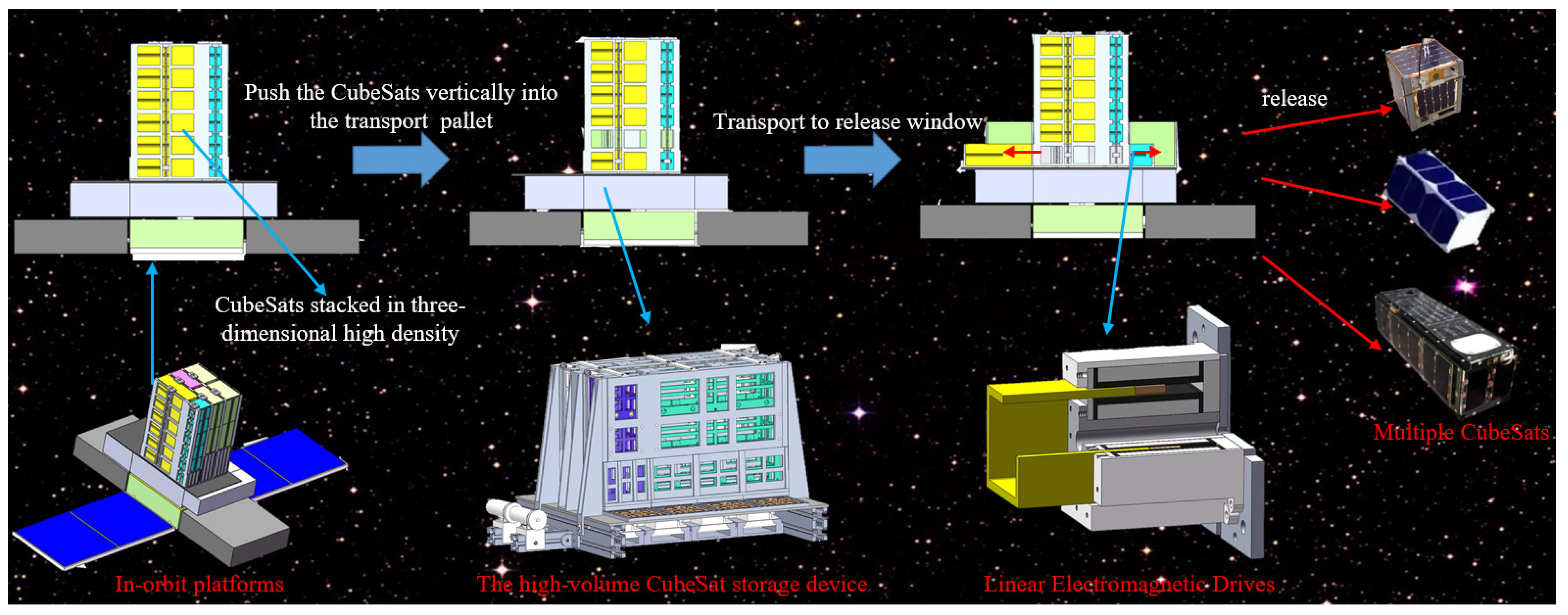
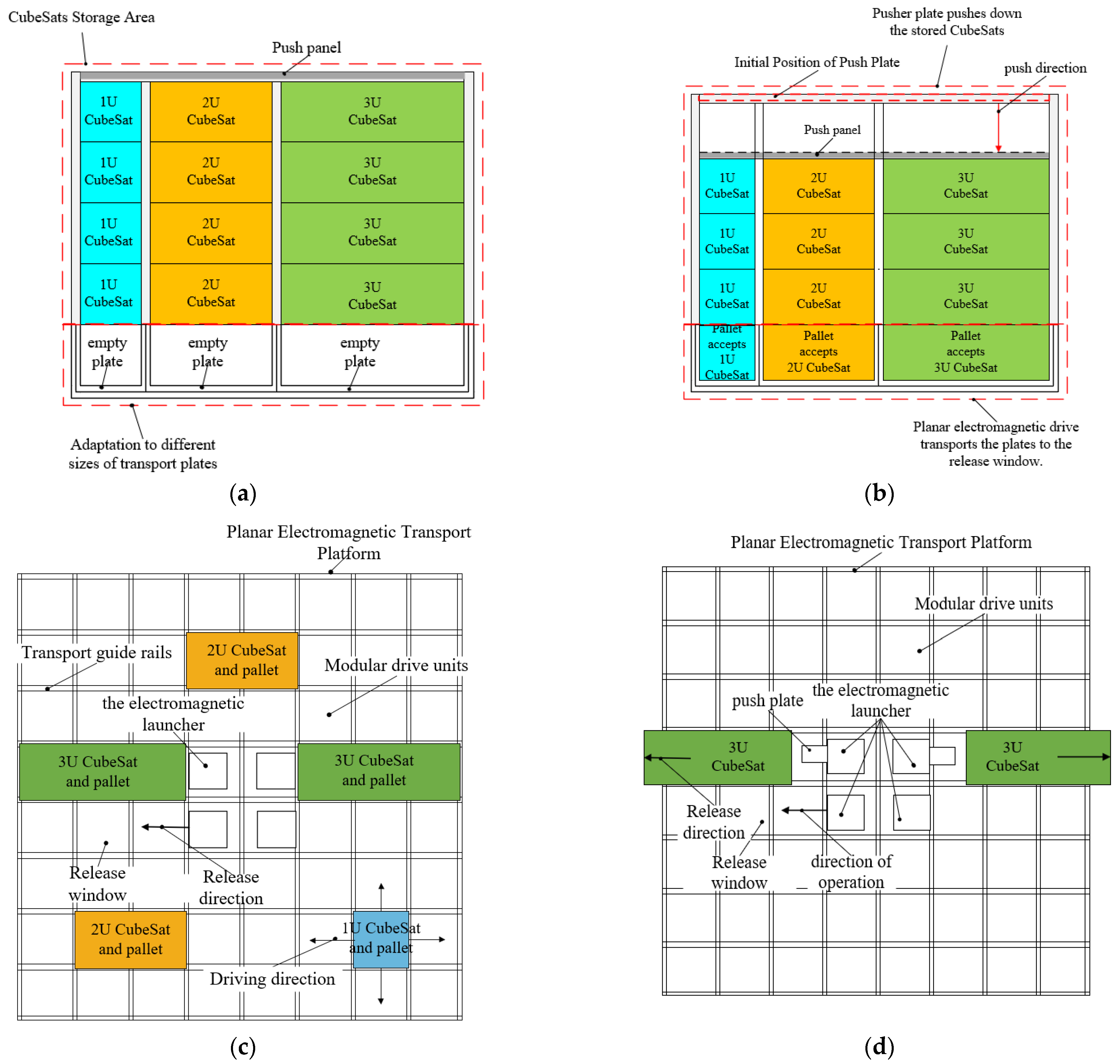
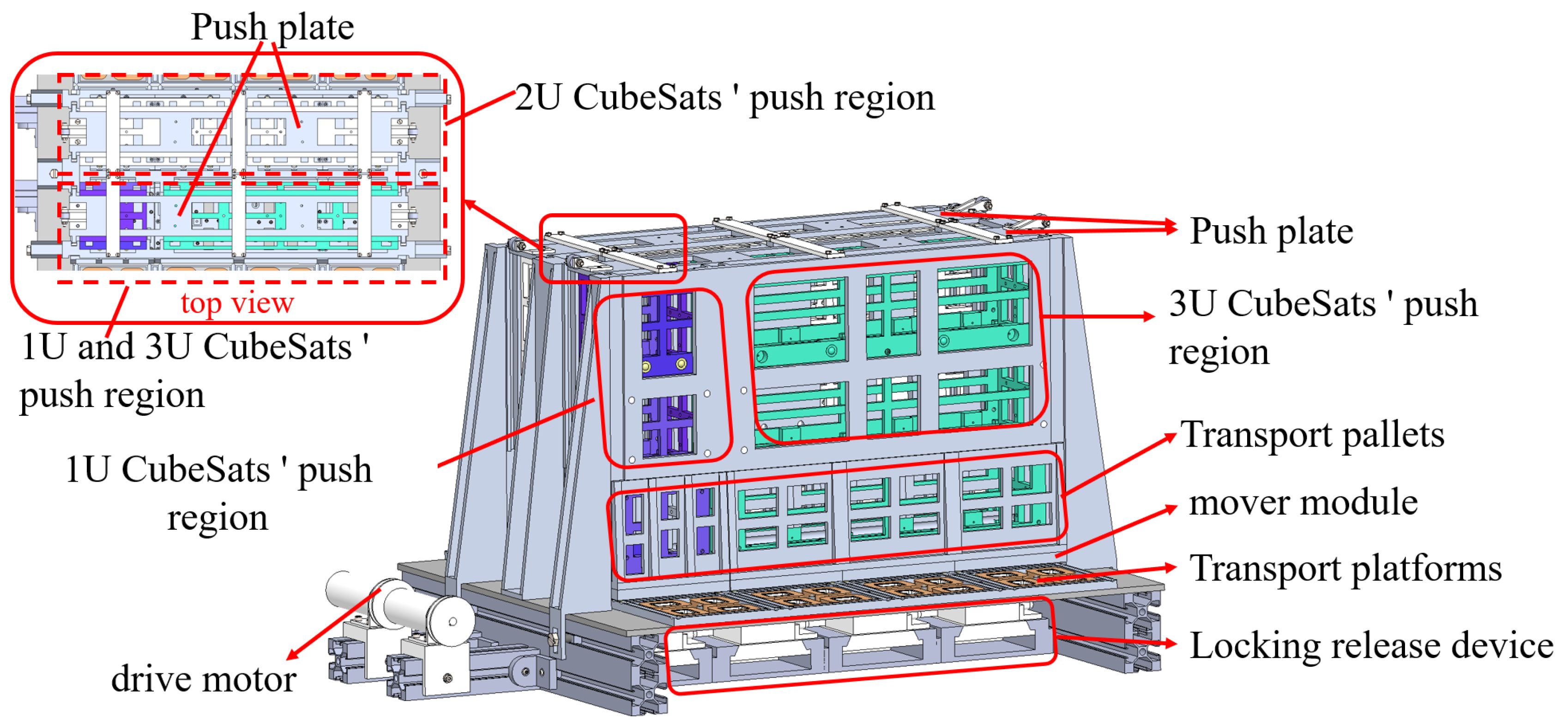
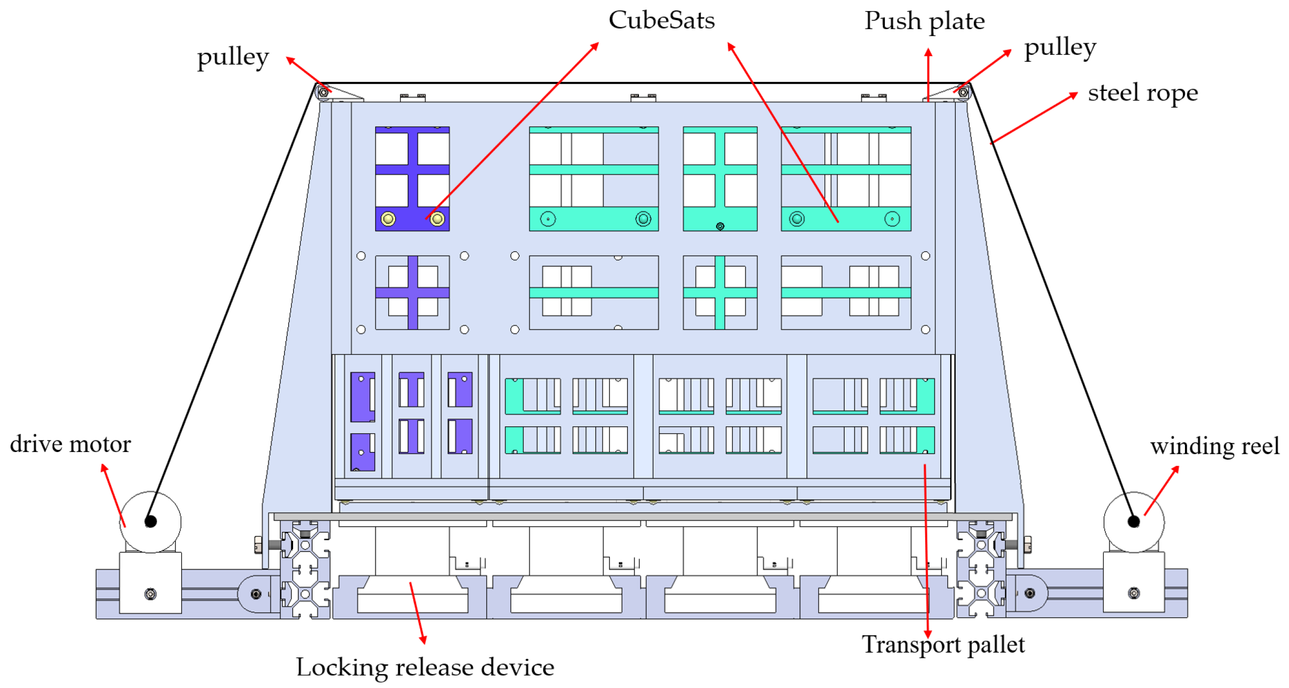
2.1. Macro Workflow

The proposed high-volume CubeSat storage device is installed on the in-orbit satellite platform, which can store, transport, and release the required types of CubeSats according to the mission requirements. The proposed CubeSat storage device stores CubeSats for LEO applications, combining the advantages of low-cost orbiting and efficient Earth observation. The number of CubeSats can be increased to expand the characteristics of the CubeSats by flying in formation. Such CubeSats are used for various types of missions, from communications to Earth observation, especially IOD/IOV (in-orbit demonstration/in-orbit validation). Experimental low-orbiting CubeSats have a short lifetime because of their low bulk mass and lack of independent propulsion. For example, the CubeSat Aoxiang 1, which is used at low altitudes (below 400 km), has a lifetime of only about 90–120 days; the LilacSat-1 has a lifetime of only three months from the time it is launched to the completion of its mission and re-entry into the atmosphere; and NASA’s CSPSTONE has a volume of 12U and a lifetime of 22 months. In this paper, the CubeSat storage device’s storage of the CubeSat is only used to verify the storage device’s storage and push performance, so its life cycle is shorter, with only a 2–3 month life. The design life of this device is 2 years, and it is not directly exposed to the space environment in the actual application process, so it has a longer life and can meet the requirements of releasing CubeSats.
The CubeSat storage device stores different types of CubeSats within the storage area formed by the side plates and the active top plate. Through vertical pushing and planar transport, the CubeSats are transported to the release position, where they are released by the linear electromagnetic device. The specific macro workflow diagram is shown in Figure 1.

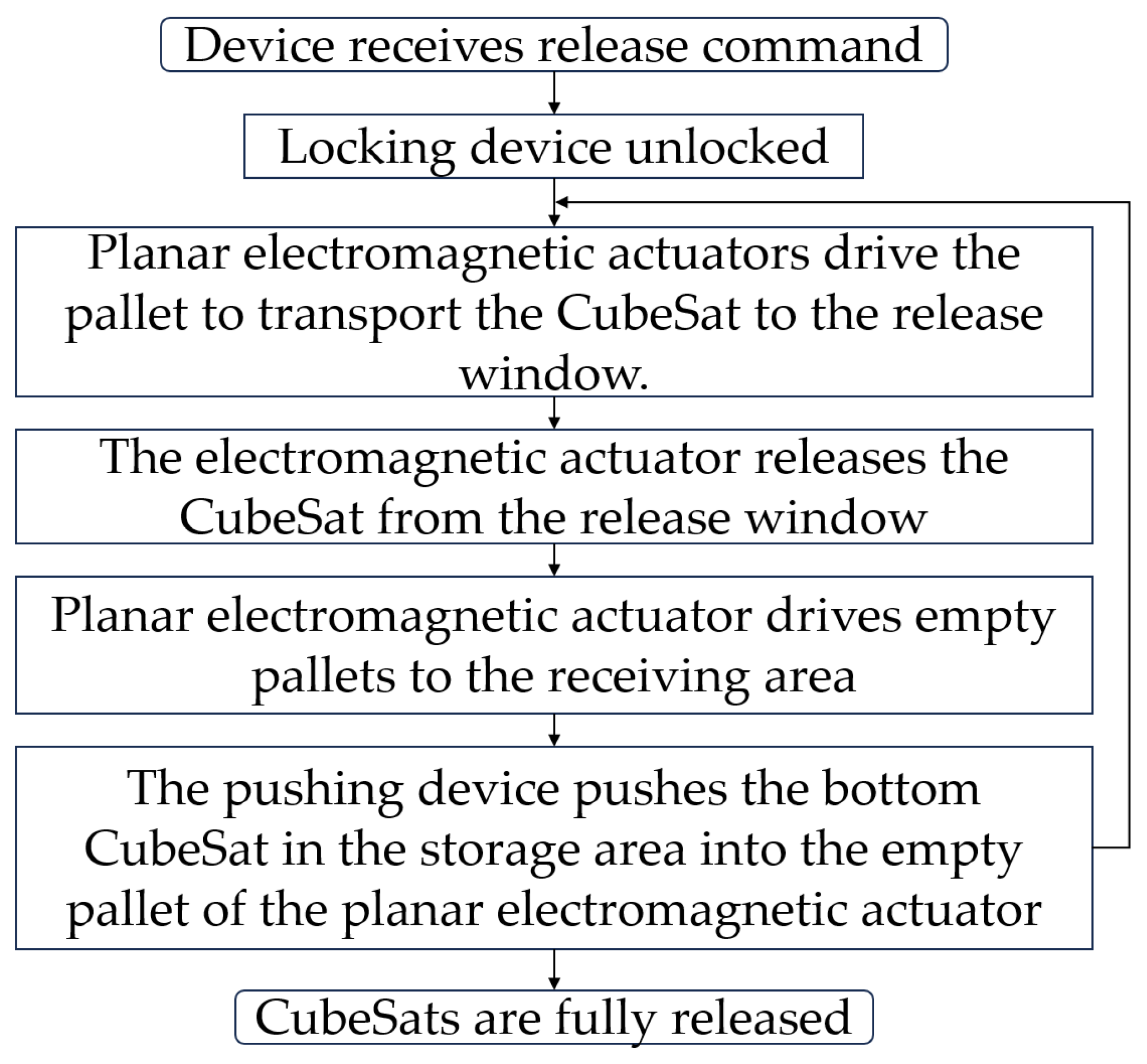
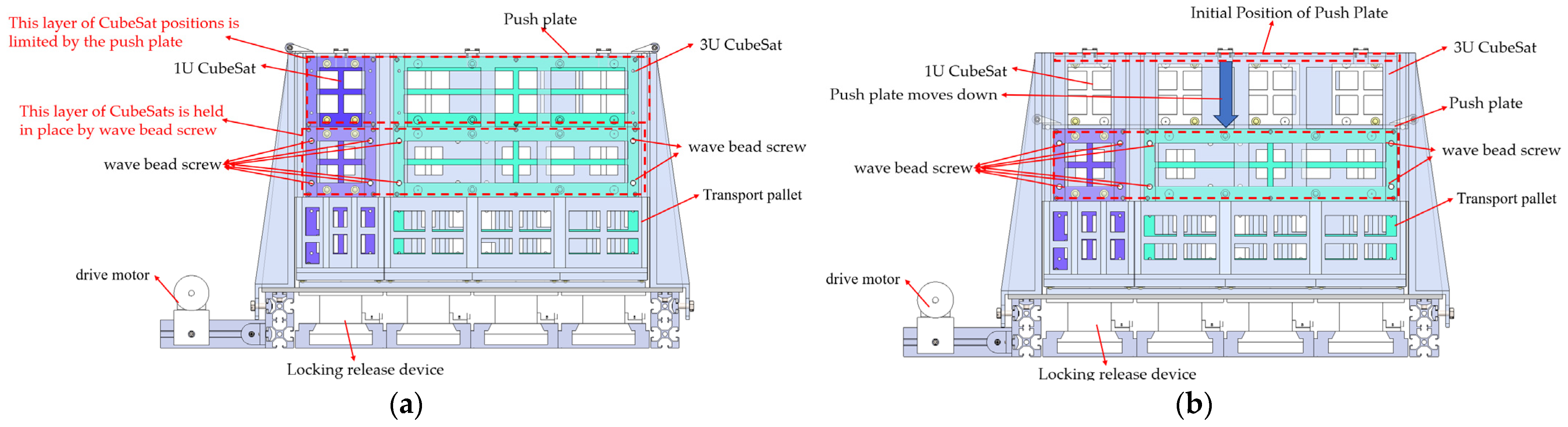
2.2. Transit Release Working Principle

For clarity in subsequent discussions, the following clarifications are provided for specific details mentioned in the text:
(1)
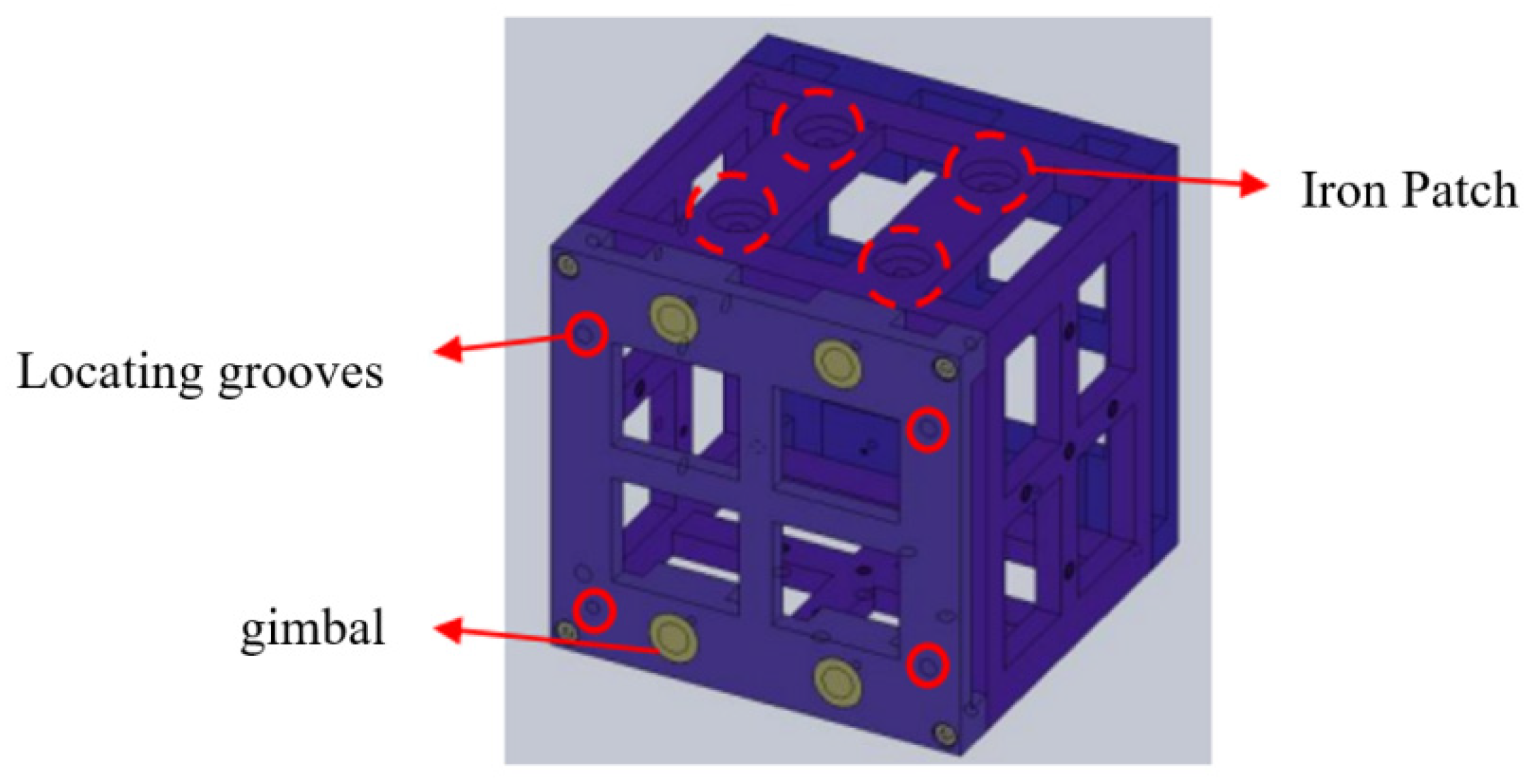
In this paper, the volume of the 1U CubeSat is assumed to be 100 × 100 × 100 mm3, the volume of the 2U CubeSat is 200 × 100 × 100 mm3, and the volume of the 3U CubeSat is 300 × 100 × 100 mm3.
(2)
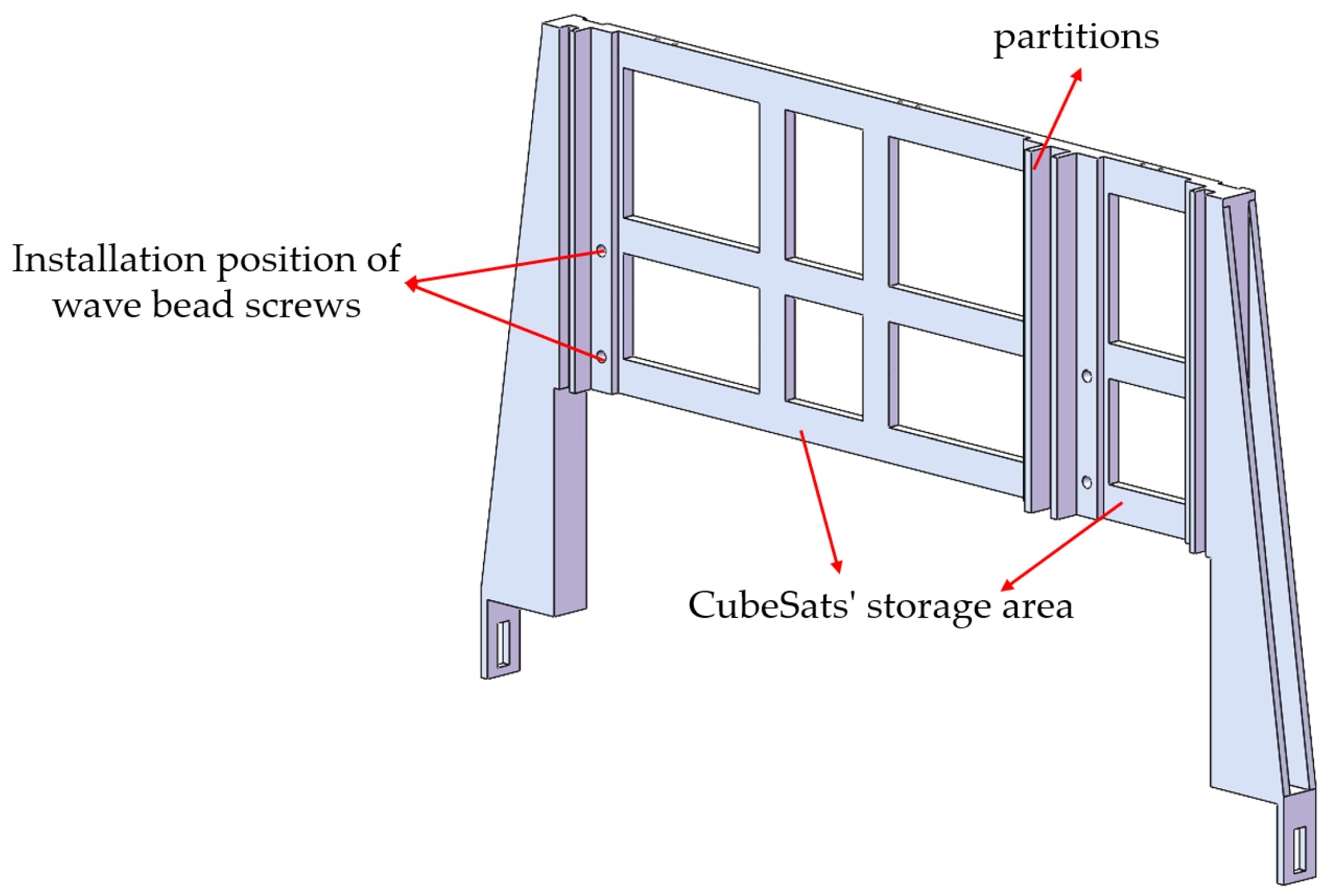
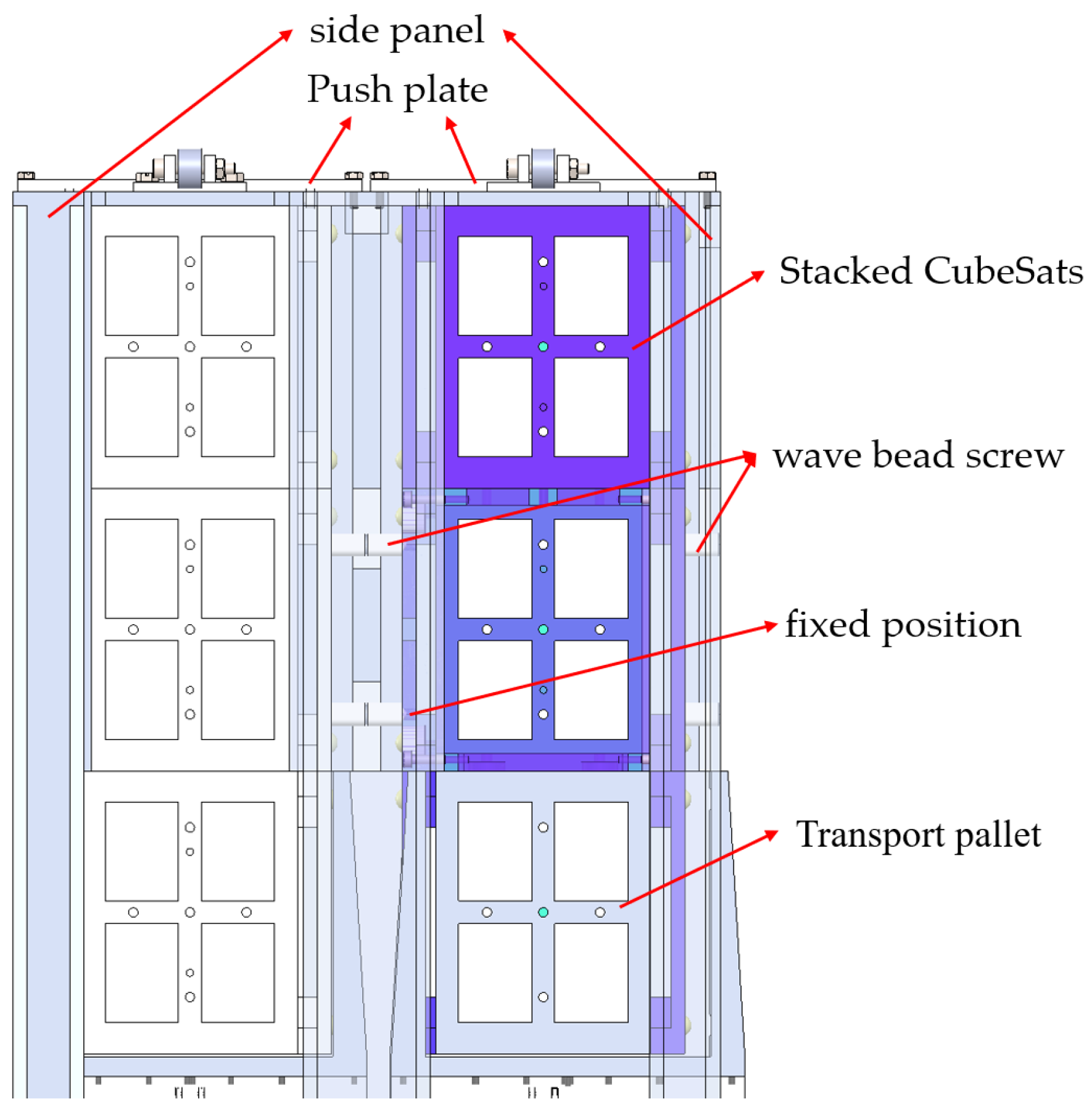
The outer part of the wave bead screw features threads that connect to the storage device. Inside, there is a spring that interacts with the end of a steel ball, serving to position and lock it in place. This structure is illustrated in Figure 2.
(3)
The ideal state corresponds to the CubeSat’s storage and post-ejection condition under uniform force distribution, collision-free ejection processes, and smooth downward motion of the motor-driven pusher plate.
To increase CubeSats’ storage capacity and density, this paper proposes a three-dimensional close-piled CubeSat storage device that enables efficient stacking and transportation. To avoid complex mechanical systems or transmission mechanisms acting one-to-one on each CubeSat, this study implements a batch operation followed by one-to-one deployment. Specifically, the approach involves a single-directional push of vertically stacked CubeSats to a two-dimensional transport platform, where they are then driven using flat motors to the release window. Then, a reusable compression device separates and releases the CubeSats. Figure 3 shows a schematic diagram of the principle of the CubeSat transit release process, and Figure 4 shows a flow chart of the CubeSat transit release process.
For CubeSats of the same specifications, they are tightly stacked in a single column with a locking mechanism providing pre-tension to counteract acceleration during launch phases, as shown in Figure 3a. Upon receiving the release command, the locking mechanism disengages. The push plates then overcome the temporary positioning resistance of the CubeSat’s roll pins, pushing the entire stack down by one layer. Consequently, the bottom layer CubeSats are transported to the pallet, while the upper layers are repositioned and temporarily held by the roll pins, as shown in Figure 3b. A single-column push process is illustrated here; however, multiple columns can be similarly processed to transport three-dimensional stacked CubeSats into a two-dimensional storage arrangement. As shown in Figure 3c, linear motors drive the transport pallet, allowing independent and non-interfering operations for parallel processing. Figure 3d depicts a voice coil linear motor used to precisely position and release the CubeSat by counteracting the release’s retrograde force, minimizing its impact on the host platform’s attitude. After release, the empty transport pallet is driven back to the corresponding column, ready for subsequent capture and transport.
Figure 5 shows a schematic diagram of the CubeSat transit process. Our device was designed with a completely different mindset than a conventional CubeSat deployer. Conventional CubeSat deployers are equipped with individual box bins for each stored CubeSat for storage, ensuring that the release environment of each CubeSat is not interfered with by other CubeSats. Conventional CubeSat deployers are unable to stack CubeSats for storage, reducing space utilization. Instead, our storage device will work with the designed electromagnetic transfer platform and electromagnetic ejection device for release, as shown in Figure 5. The transfer pallet transfers the CubeSats loaded in it to the designated location on the electromagnetic transfer platform. The electromagnetic ejection device releases the CubeSat for launching. After that, the transfer pallet returns to the bottom of the storage device to continue receiving the CubeSats. A wire rope with a pusher plate pushes the whole row of CubeSats downwards until the permanent magnets on the transfer tray attract the patches on the CubeSats. Subsequently, the CubeSat will enter the transfer tray, and at this time the motor will turn off and push the plate to stop moving. The upper layer of the CubeSat is stuck by the wave bead screw on the storage device to achieve passive locking. Repeating the transfer, release, and push actions, the CubeSats can be stacked to achieve non-interference in their separation and release. In the design process, we stacked different kinds of CubeSats for storage, and separated the stacked CubeSats by a motor, a wire rope, and a pusher plate, so that the stacked CubeSats would not affect each other when they were released. Our device utilizes a lower volumetric mass of wire rope, push plates, and wave bead screws for separation, reducing the additional mass. This design, in conjunction with a storage device for stacking and storing CubeSats, effectively improves space utilization while providing great expandability.

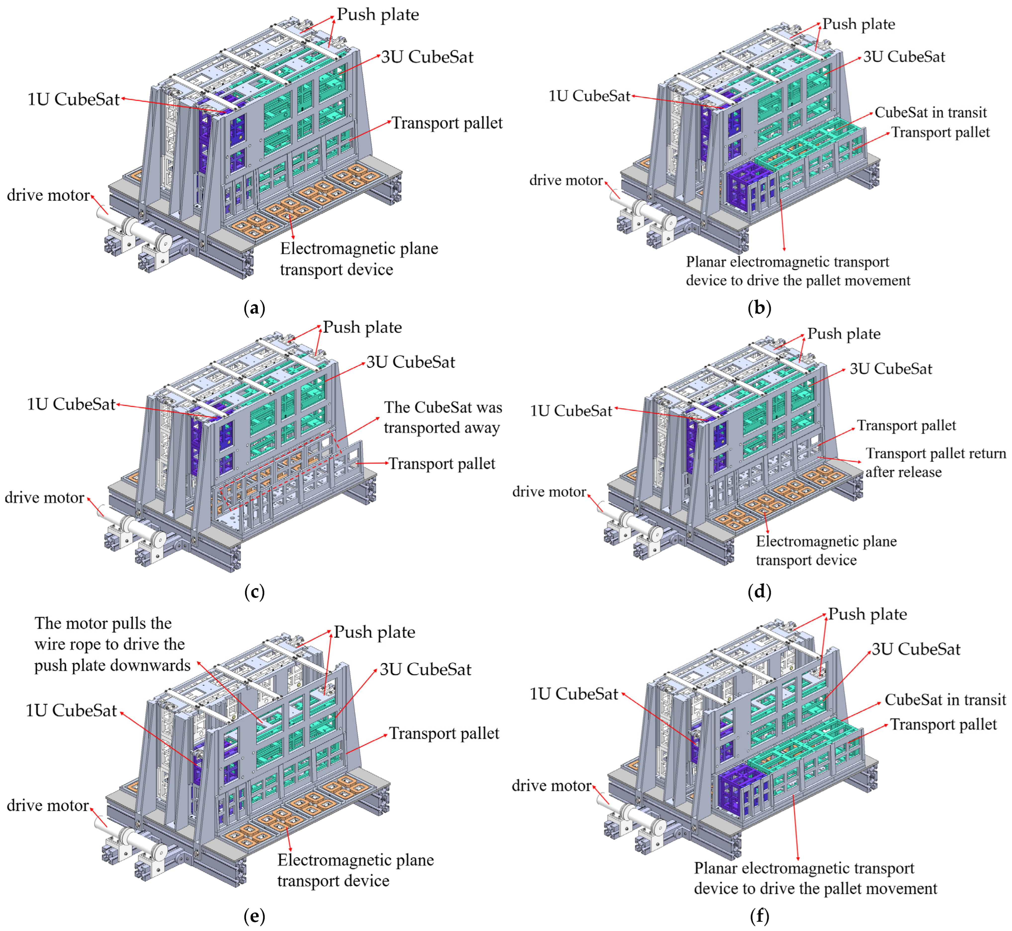
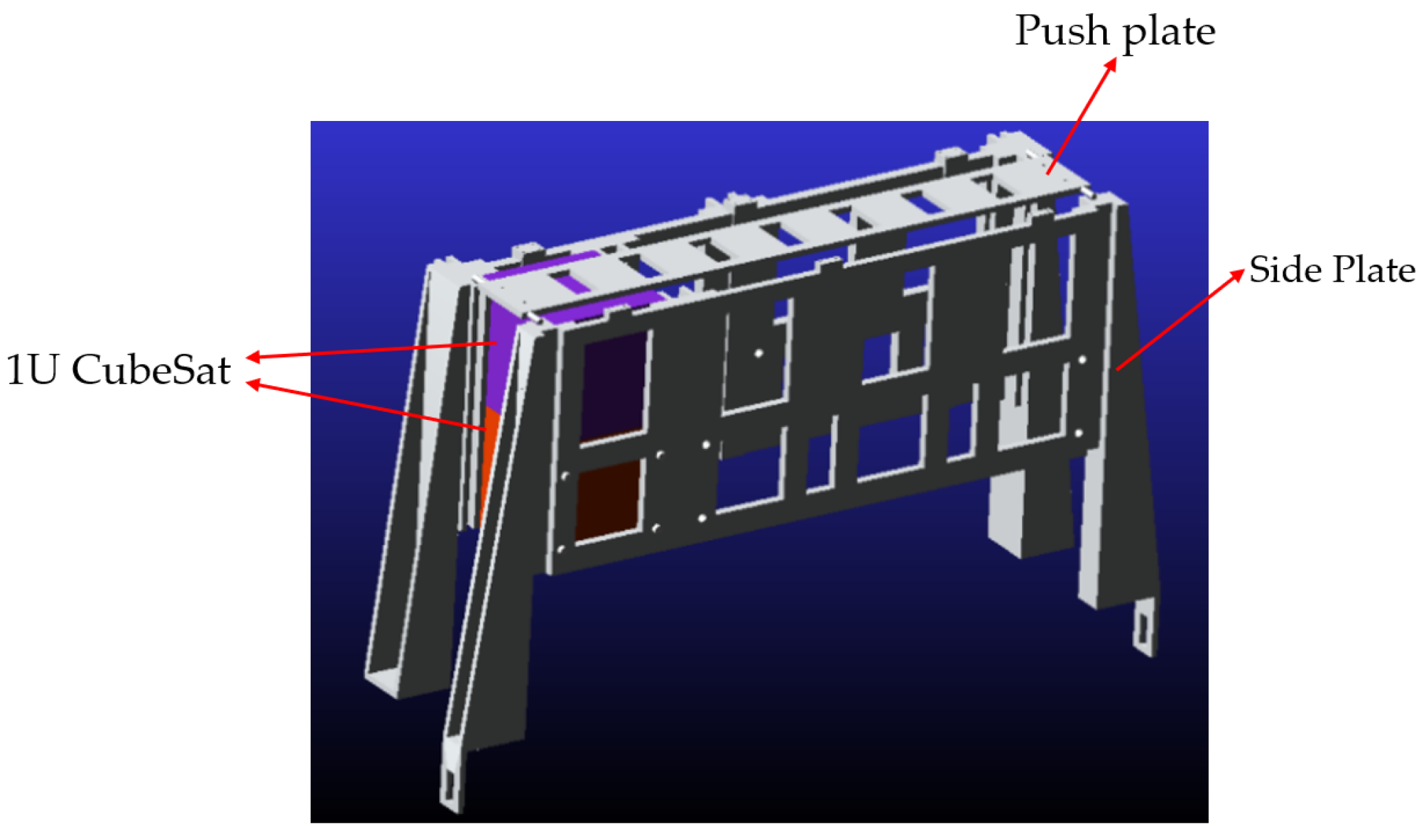
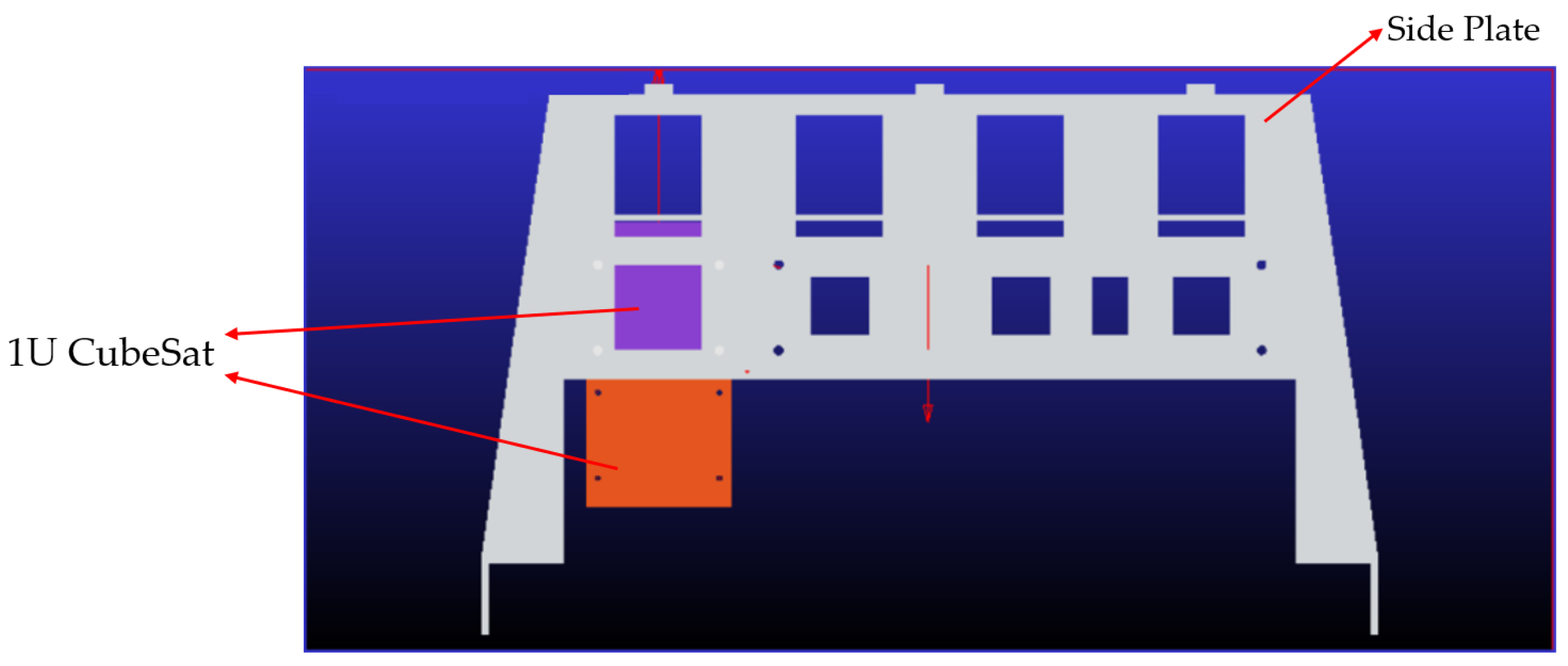
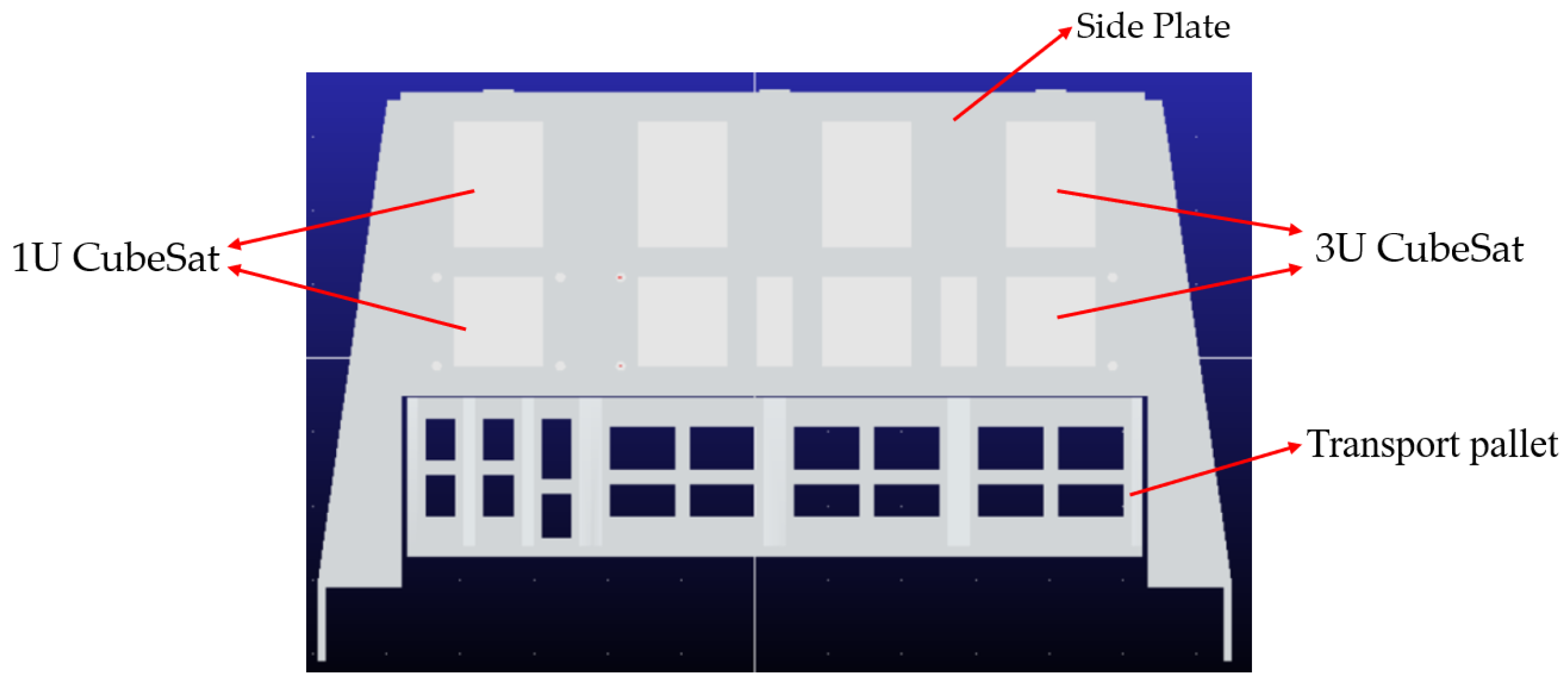
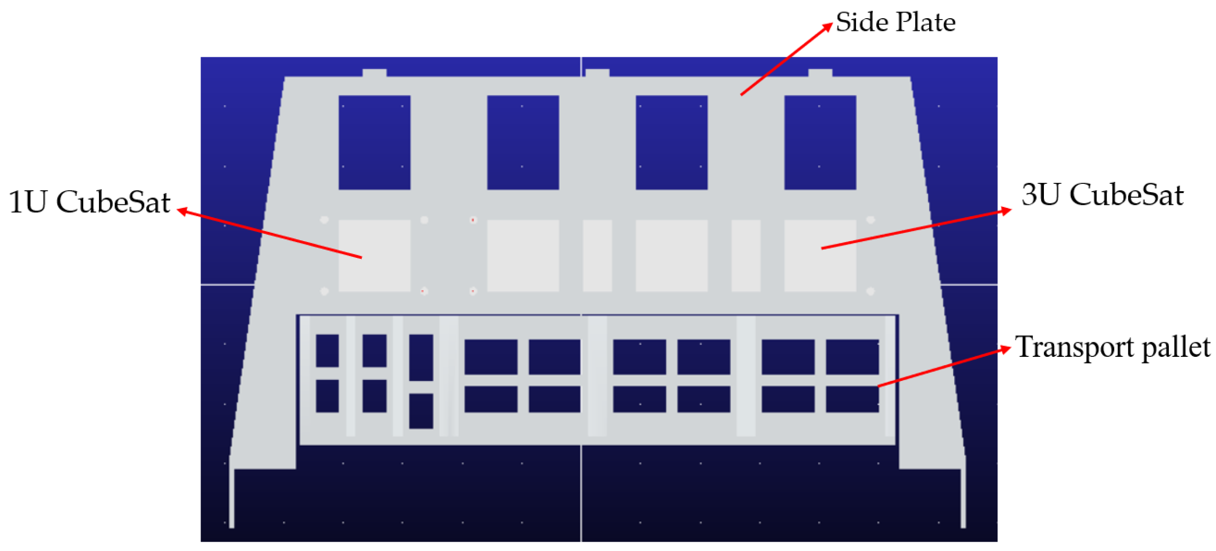
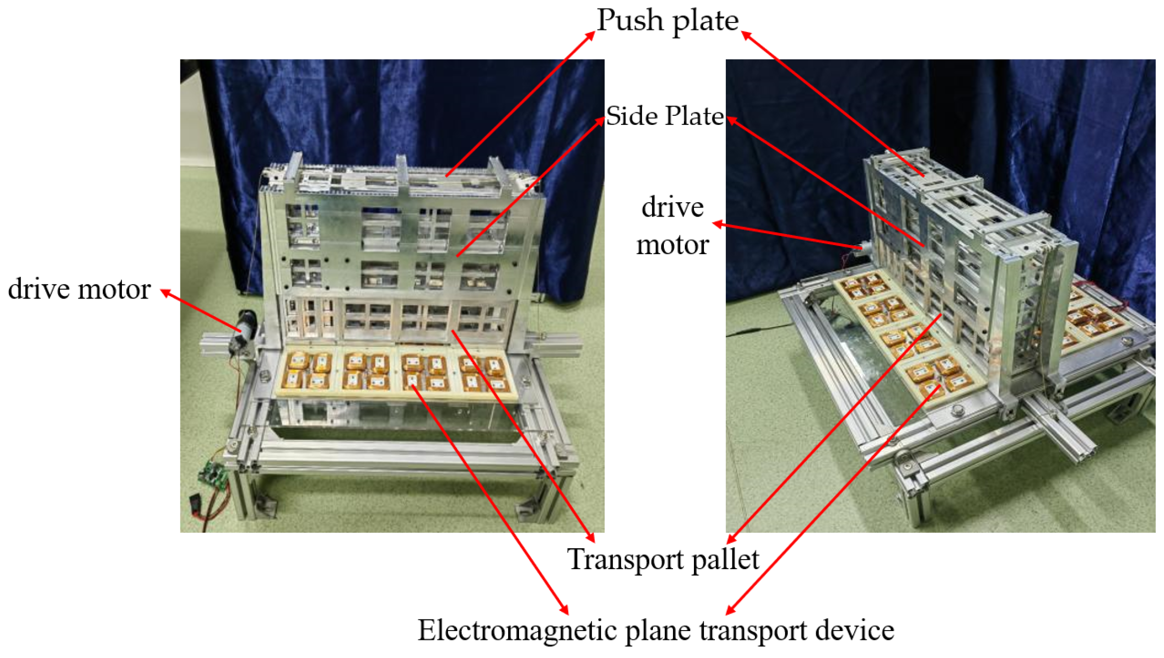
2.3. Principle of Storage Device

The CubeSat storage device, as illustrated in Figure 6, can accommodate three specifications of CubeSats: 1U, 2U, and 3U. Initially, the system is secured by a release lock mechanism, with CubeSats stacked within the pusher area. Upon lock disengagement, push plates are actuated to downward-force the CubeSats into the transport pallet. The pusher system is driven by motors. Once released from the pusher, CubeSats are transported onto the transport pallet in the transport zone. The core of the transport zone consists of a 4 × 4 array of drive modules, each containing four coils. When energized, the coils generate electromagnetic forces that propel actuator modules with permanent magnets along the x- and y-axes. These modules are fixed on the transport pallet, enabling CubeSats to be transported to the release window.
Taking the 1U and 3U transport system’s outer panel of the storage area as an example, its external structure is shown in Figure 7. The structure of other side panels is similar and will not be elaborated upon here. The outer panel is equipped with wave bead screws to secure the CubeSats, avoiding the use of active locking devices that would consume a significant amount of space. Additionally, partitions are incorporated to separate CubeSats of different sizes. According to the storage of CubeSats, specifications can be set up in different positions of the partition, to achieve the adaptation for different types of CubeSats.
For example, the external structure of a 1U CubeSat is illustrated in Figure 8. The structures of the 2U and 3U CubeSats are similar to that of the 1U CubeSat, differing only in size. The housing has grooves that work with the push device to achieve positioning during the push process. The housing contains four gimbals, which guide the CubeSat into the transport pallet during its entry process. The bottom face of the CubeSat is equipped with circular iron patches, which are effective during the CubeSat’s entry into the transport pallet from the push zone.
Taking the 1U CubeSat transport pallet as an example, its external structure is shown in Figure 9. Other types of CubeSat transport pallets are similar to the 1U CubeSat transport pallet and can be assembled from multiple 1U transport pallets. The transport pallet is divided into a receiving pallet and a mover unit. The inner wall of the receiving pallet is equipped with grooves that cooperate with universal joints for sliding. The bottom of the receiving pallet is installed with magnetic blocks that attract the ferromagnetic plates installed on the CubeSats, assisting in the receiving task. The mover unit is equipped with four Halbach permanent magnet arrays arranged in a staggered pattern. They move through gimbals on a planar electromagnetic transport platform to achieve transport.
Before the transport begins, CubeSats are stacked within the push device, as shown in Figure 10. The push device can accommodate two tiers of CubeSats, and the transport pallet can also hold one layer of CubeSats. When the locking release mechanism unlocks, it creates a gap between the deployment mechanism and the transport pallet. This prevents friction between the transported CubeSats and those in the deployment mechanism. A motor-driven mechanical structure is used for pushing. Considering that using two separate motors on both sides of the device may not guarantee synchronization, a single motor is installed on one side, while the other side is fixed. One end of the steel wire rope is wound around the motor shaft on one side of the device, and the other end is passed over the pulleys installed on both sides of the push plate and fixed to the other side of the device. When powered on, the rotation of the motor shaft drives the steel wire rope winding wheel to tighten the steel wire rope. The force generated by tightening is used to move the push plate downward, initiating the pushing process. Each CubeSat push area requires a separate motor and a set of push plate components. A plan view of the push plate component is shown in Figure 11. To prevent the push plate from jamming during the pushing process, an externally threaded bearing is installed at the contact position between the push plate and the side plate of the deployment mechanism.
In the fixation of CubeSats, a set of wave bead screw mechanisms is employed. Specifically, wave bead screws are installed at the bottom layer of the push device, as shown in Figure 12. Additionally, each type of CubeSat housing is fitted with grooves that complement the wave bead screws and nuts. When the push device is stationary, the wave bead screw is embedded into the groove of the CubeSat, thereby achieving positioning; during operation, once the pushing force reaches a certain level, the compression of the spring within the wave bead screw allows the CubeSat to continue moving. This design enables the sequential pushing of multilayer CubeSats. Once the bottom layer of CubeSats is pushed into the transport pallet, the system halts the pushing process. Then, the top layer of CubeSats remains stationary due to the wave bead screw mechanism, as depicted in Figure 13. After the bottom layer of CubeSats is launched, the transport pallet returns to the lower part of the push device, at which point the push device resumes its operation.
The feature of this scheme lies in that the CubeSats are densely stacked in a three-dimensional manner within the container. It achieves columnar storage unit lock and push to reduce the number of locking devices and actuators and save a substantial amount of actuation space. Additionally, it allows for arbitrary combination designs of different columns based on effective space, demonstrating excellent adaptability and generality. The push device and planar electromagnetic actuator are located at the container ends to avoid occupying internal storage space, effectively increasing the payload capacity and accommodating quantity. The annular electromagnetic actuators are symmetrically arranged to generate forces in opposite directions for cancellation, thereby reducing their impact on the platform’s attitude. Using the electromagnetic force-driven planar transport method avoids the need for a complex mechanical transmission system, significantly lowering the overall volume and mass. Notably, the modular design of the drive units allows for easy expansion of the transport range, suitable for transporting CubeSats of various configurations. Multiple subunits operate independently without interference, enabling efficient parallel transport. The annular electromagnetic actuators regulate thrust via current adjustment to achieve precise speed control and release, enhancing spatial deployment accuracy. They also feature a fast response speed and high-frequency actuation.
The existing CubeSat deployers are compared with the storage device proposed in this paper to analyze the speed of CubeSat deployment, satellite capacity, and other aspects, and then evaluate the performance of this device, and the performance comparison table is shown in Table 1. Considering that some of the specific parameters of the CubeSat deployers have not been published or are old and missing information, a fuzzy comparison is made in the comparison table using the reference materials found.

3. Modal Simulation of Devices and Thermal Simulation of Space Environment

Since the storage device works in space, the high and low temperatures, vibration, and radiation in the space environment and other external conditions will inevitably affect the working performance of the storage device. The effects of high and low temperatures are manifested in the thermal strain generated by the device at different temperatures; the effects of vibration are manifested in the vibration generated when the device is launched into space or when it is reorbited, destroying the device’s structure; and the impact of particles when it is subjected to radiation will result in the damage of the device and a reduction in its life span. By analyzing the modes and thermal strains of the device, the effects of the space environment on the device can be effectively analyzed. Regarding the radiation factor, since the device is located inside the mother star platform in its operating state, it is not affected by radiation particles. Therefore, in this paper, the vibration factor and the ambient temperature are simulated and analyzed for the time being.

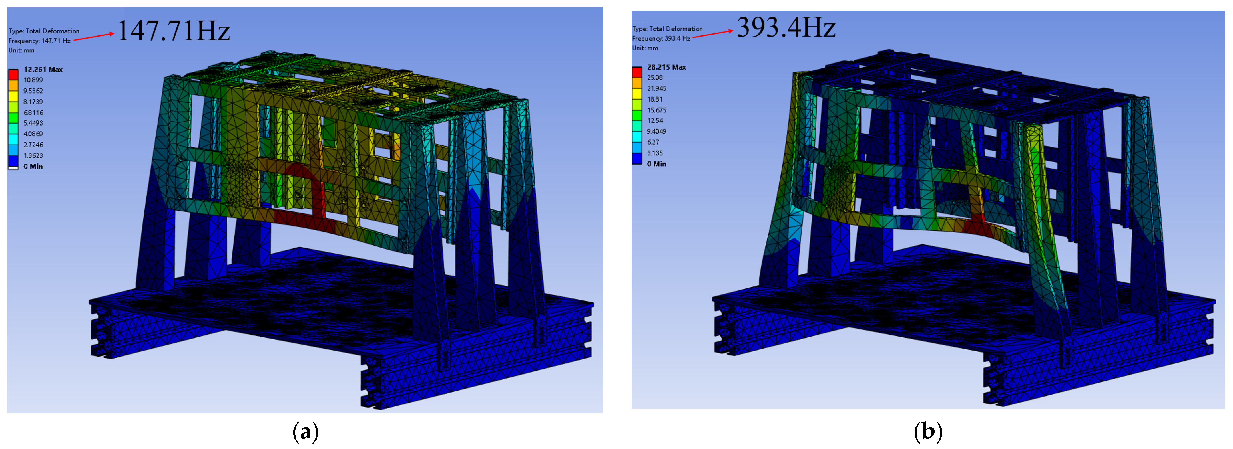
3.1. Modal Simulation of Devices

As one of the intrinsic properties of a structural system, modes are the vibration response of a mechanical structure under combined vibration excitation in a specific frequency range. The purpose of modal analysis is to identify the modal parameters of a structural system, such as the intrinsic frequency, modal shapes, and damping ratio. The results can be used to optimize the dynamic characteristics of the structural system and provide a basis for vibration testing, fault detection, and diagnosis of the structural system. Considering that the device is applied in a space environment, where vibrations are generated either during launch or during reorbiting, these may cause irreversible damage to the device. For this reason, a modal analysis is carried out for the storage device, and the simulation results are shown in Figure 14 and Table 2.
As shown in the graph and table, the fundamental frequency of the device is 147.71 Hz, which meets the design specification of greater than or equal to 100 Hz. From the first-order and sixth-order modal vibration diagrams, it can be seen that after the device is affected by the vibration factor, the deformation mainly occurs in the outer storage side panels. The higher fundamental frequency ensures the stability of the device when it is subjected to vibration, and the larger amount of 100 Hz exceeds the requirement, further proving that the device can withstand vibration in the space environment.

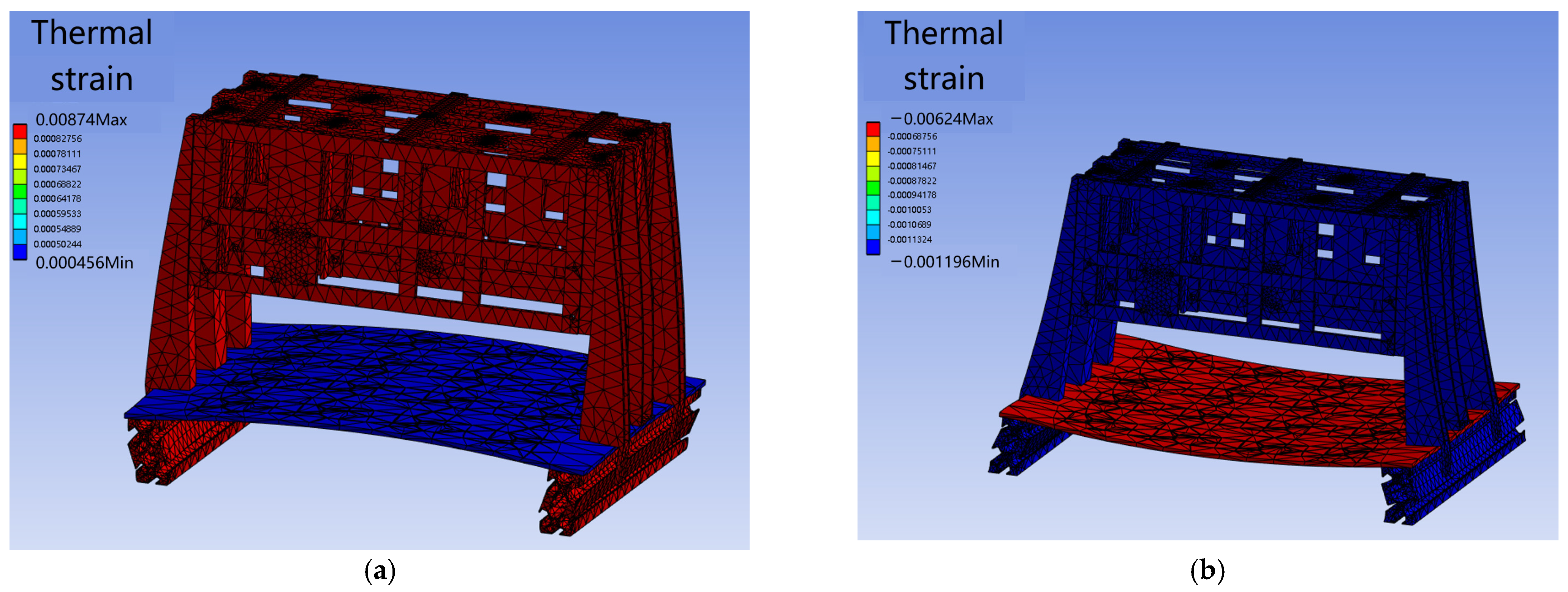
3.2. Thermal Simulation of Space Environment

Consider the application environment of the storage device, in the actual space environment, it may suffer heat, vibration, radiation, and other external environmental interference. Among them, changes in the space temperature environment on the image of the storage device are manifested in the structure as the thermal strain, which may cause a wide range of structural deformations, so that the storage of the CubeSats is not stable, and cannot be pushed. Thermal simulations of the device are performed to offer a reference for practical system use. Drawing from standard temperature ranges of LEO satellite components like star sensors, phased-array antennas, and propellant tanks [28], temperatures are set to shift from room temperature to 60 °C and −30 °C rapidly. Figure 15 presents the corresponding horizontal thermal strain.
From the simulation results, it is seen that the tray will produce the deformation effects of thermal expansion and contraction under a high- or low-temperature environment; the thermal strains produced by the device are 0.0087 and −0.00624 under 60 °C and −30 °C, respectively, and the stresses and strains are concentrated in the weak part of the bottom conductor plate connecting with the side plate of the storage device.
Under the specified temperature conditions, the device meets the strength requirements. These findings provide valuable references for the practical space applications of the system and subsequent research on CubeSat deployment mechanisms. Future improvements may involve integrating thermal control components to enhance the system’s temperature adaptability, along with vacuum thermal testing to further validate design reliability.
Additionally, considering the complexity of actual space environments, pre-deployment verification should include low-frequency sinusoidal vibration and high-frequency random vibration tests to assess vibration performance. System-level integrated irradiation test chambers should also be utilized to simulate space radiation environments and evaluate the system’s radiation tolerance.

4. Characteristics Analysis

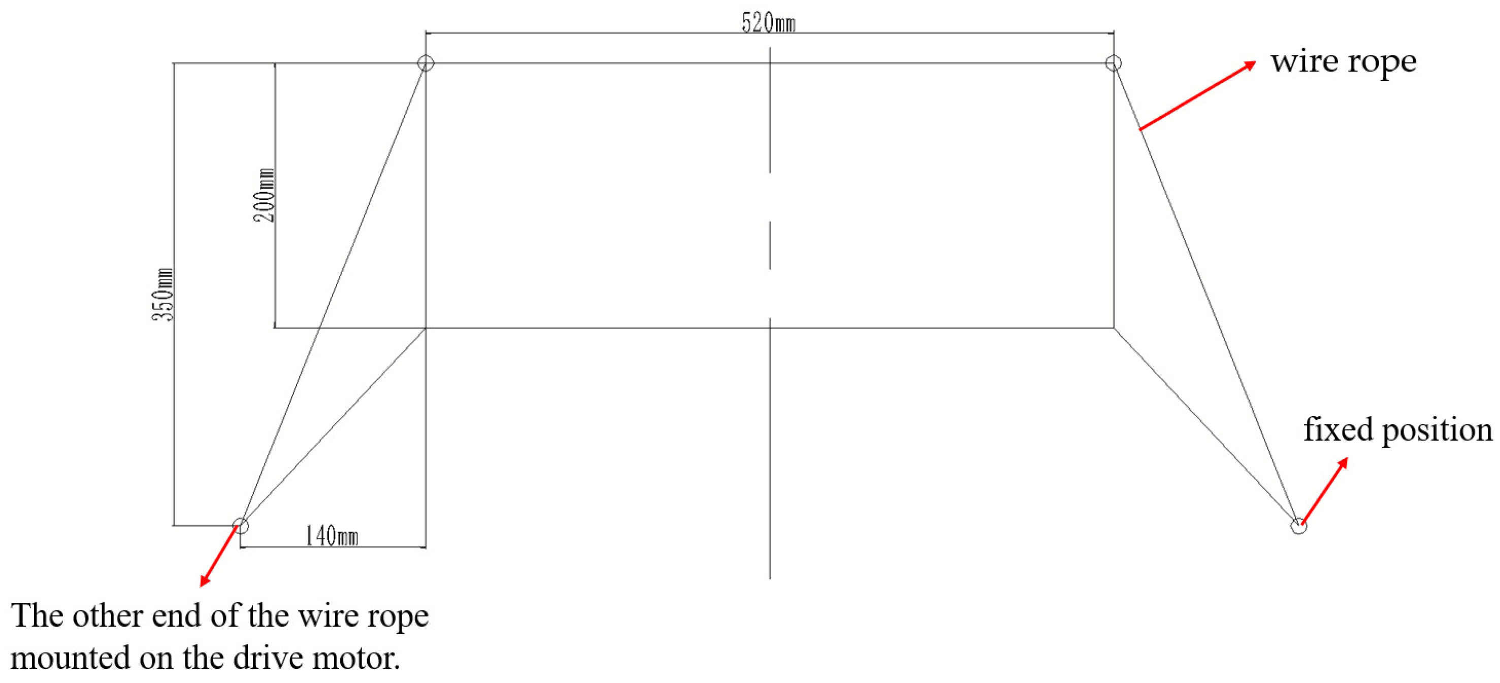
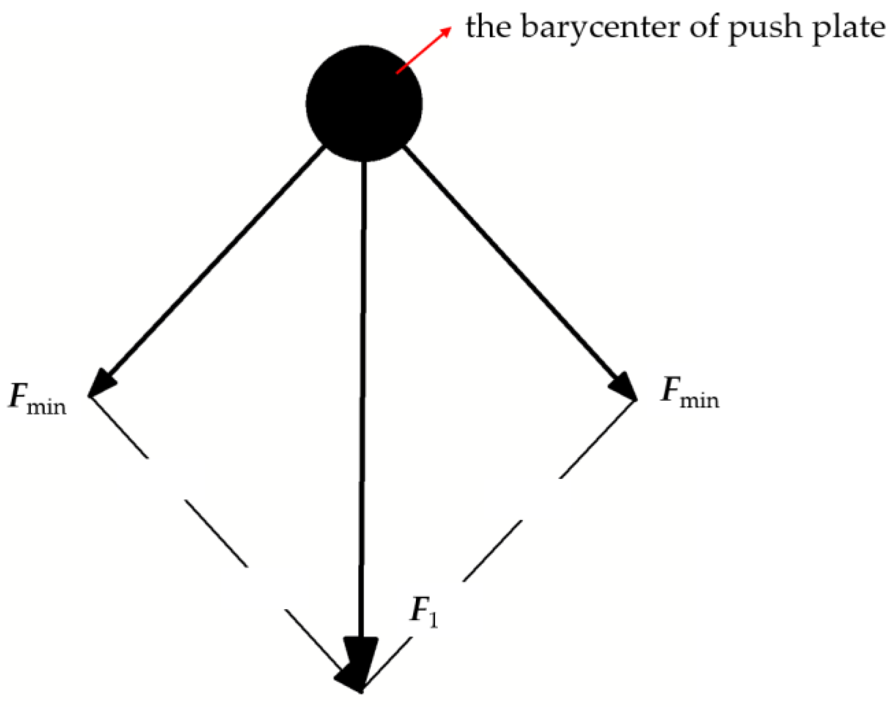
4.1. Push Motor Selection

The calculation of the required steel wire length and motor-related parameters involves abstracting the pushing device as a simplified diagram, such as Figure 16. The position where one side of the steel wire is fixed is symmetric to the winding on the motor shaft. For ease of calculation, the diameters of the pulleys installed on the push panel and those wound around the motor shaft are disregarded in length calculations.
The required length of wire winding should be longer than the length initially not taken up by the winding on the line pulley in the push device’s initial position. Using the Pythagorean theorem, the distance l1 between the winding pulley and the left-end pulley is computed.
l 1 = 140 2 + 350 2   ( mm ) = 376.96   mm
If l1 = 380 mm, then the total winding length L should be at least
L min = 2 l 1 + 520   mm = 1280   mm
If the total winding length is taken as L = 1400 mm, these data will serve as a reference for the subsequent ground test system setup.
Based on mechanical principles, since the motor provides a constant torque, the force on the push panel decreases as it gradually lowers. To ensure that the CubeSat can be smoothly pushed by the push panel, the vertical component of the force acting on the push panel must always be at least 100 N. The designed winding wheel has a diameter of 12 mm.
Under zero-gravity conditions, the forces acting on the push panel are the combined tension from both sides of the wire, directed vertically downward, as illustrated in Figure 17.
From mathematical principles, the minimum force Fmin provided by the motor is calculated as follows:
F min = F 1 2 sin α
where F1 is the combined thrust force on the pusher plate, taken as 100 N; α is the angle between the tension and the horizontal direction; and tan α = 15/14.
Solving for Fmin gives approximately 68.39 N. Using a 36GP-555 DC planetary reducer (Manufacturer’s name is MYDJ, place of origin is Guangdong, China), its rated torque is expressed in kgf·cm, so the required minimum torque from the motor is calculated as follows:
where R is the radius of the winding wheel, taken as 6 mm.
Solving for T yields T = 11.63 kgf·cm. Choosing a motor with a rated torque of 14 kgf·cm, its main parameters are listed in Table 3.
A standard plain key is used to connect the motor and pulleys. The key width is b = 2 mm, height h = 2 mm, and length L = 14 mm. The compressive strength is verified as follows:
σ p = 2 T d k l
where T is the torque transmitted by the connection (N·mm); d is the shaft diameter, 8 mm; k is the height at which the key engages with the pulley slot, 1 mm; and l is the effective length of the key, l = L − b =12 mm.
The load is characterized as slight impact (frequent start and stop), the allowable compressive stress is 100–120 MPa, and the calculated stress “ σ p ” is 28.58 MPa, which is less than the allowable stress. Therefore, it meets the requirements.

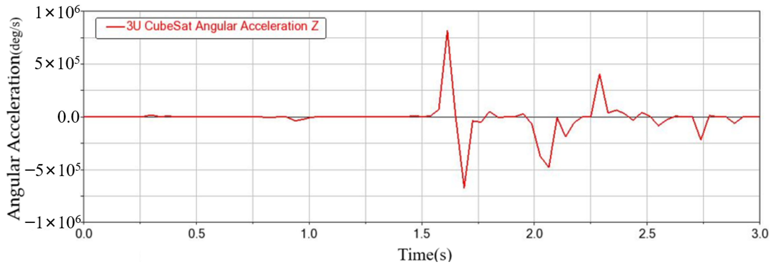
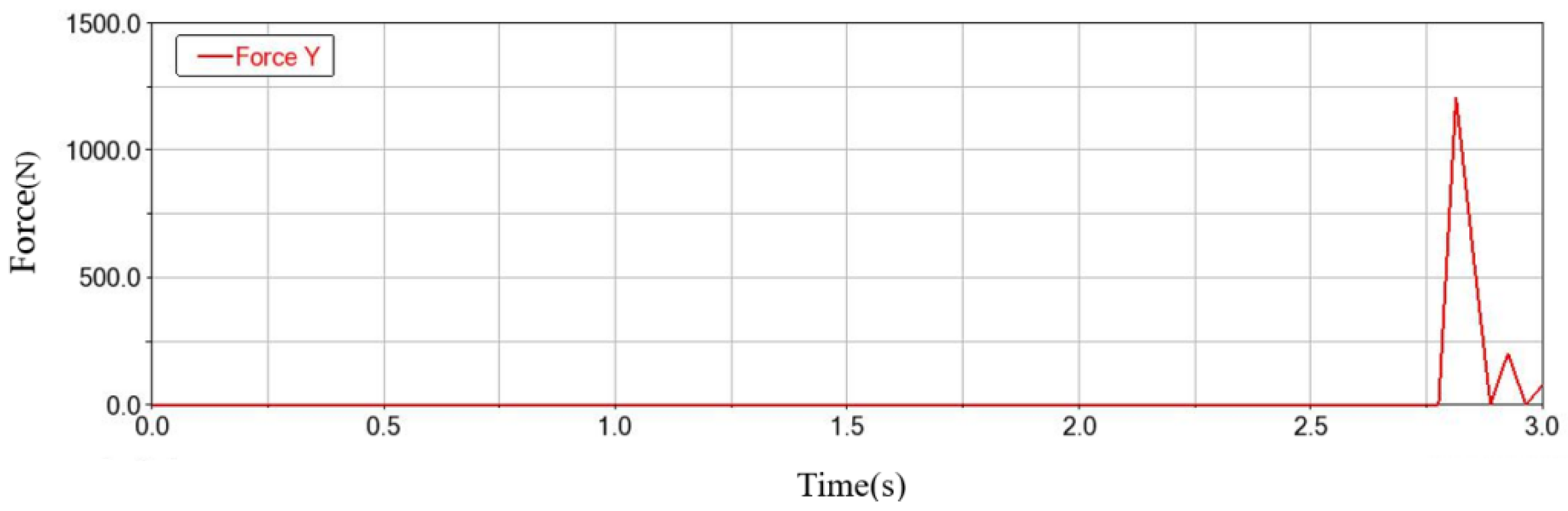
4.2. Analysis of Push Process Dynamics

To analyze the pushing process of the CubeSats in the storage device, the whole row of CubeSats is considered a whole for the dynamics analysis, considering the close contact between the CubeSats. Figure 18 depicts the motion process of the whole column of CubeSats in the storage device. Figure 18a presents the force analysis diagram of the storage state, where the CubeSat’s position is restricted by the pushing plate, side plate, and wave bead screw. Shown in Figure 18b is the force analysis diagram in the pushing process. In the pushing process, the CubeSat is subjected to the downward pushing force of the pushing plate, the contact force with the side plate, the sliding friction force of the side plate, the contact force of the wave bead screws, and the friction force of the wave bead screws, and the kinetic energy theorem is used to construct a kinetic model of the pushing process.
F P x f S x f b x = 1 2 m v 2 0
where F P is the push force of the push plate, f s is the friction between the CubeSat and the side plate, f b is the friction between the CubeSat and the wave bead screw, and x is the push distance of the whole row of CubeSats.
The friction mentioned above can be expressed in the following way.
f S = μ S F S f b = μ b F b
The above is the expression of the kinetic model in the ideal state. At the same time, in the actual pushing process, the pushing force of the pushing plate may not be located in the center of mass or the collision between the CubeSat and the side plate. These, in turn, need to be verified by the simulation of the actual process.
In particular, it is stated here that the assumption of a constant coefficient of friction and simplified contact dynamics used in the simulation may indeed introduce some deviation in the actual performance prediction. Considering the effects of the limitations of a constant friction coefficient, firstly, the friction coefficient of the actual contact surfaces dynamically varies with the sliding speed, contact pressure, and ambient temperature during movement, and the lubricating oil film, oxidized layer, and wear debris also cause the actual μ-value to fluctuate. The friction force also fluctuates, and consequently, the acceleration of the CubeSat is not stable during the moving process. Different combined forces on different surfaces may lead to contact collisions between the CubeSat and the sidewalls of the device, affecting the movement. The simplified contact dynamics avoid the collision between the CubeSat and the sidewalls during the motion process and reduce the energy distribution problem during the real collision process, as well as the asymmetric pressure distribution that occurs during multi-body contact. The above problems have a great impact on the accuracy of the constructed kinetic model of the thrust process, and the adoption of these assumptions does limit the accuracy of the model under extreme working conditions (e.g., high-speed heavy loads, micro- and nanoscale operations, etc.). However, in this paper, the kinetic model is constructed only to analyze the force process during the motion of the storage device, and thus to determine the required parameters of the device in advance for the subsequent simulation and experimental process, for which we adopt a simplified method to determine the parameter range. In the simulation process, factors such as the positional deviation of the center of mass of the CubeSat, different surface roughness, and changes in the coefficient of friction at different positions can be taken into account for a more accurate simulation and analysis. In the actual experimental process, the output rotational speed of the motor is fixed, and the friction coefficients between the devices are values determined in the actual environment, so the establishment of this simplified dynamics model will not affect the subsequent analysis of the actual experimental and simulation processes.
In the subsequent simulation and experimental process, we did observe the collision of the CubeSat in the process of motion and small fluctuations of the speed, which are the same as the assumptions made in advance.

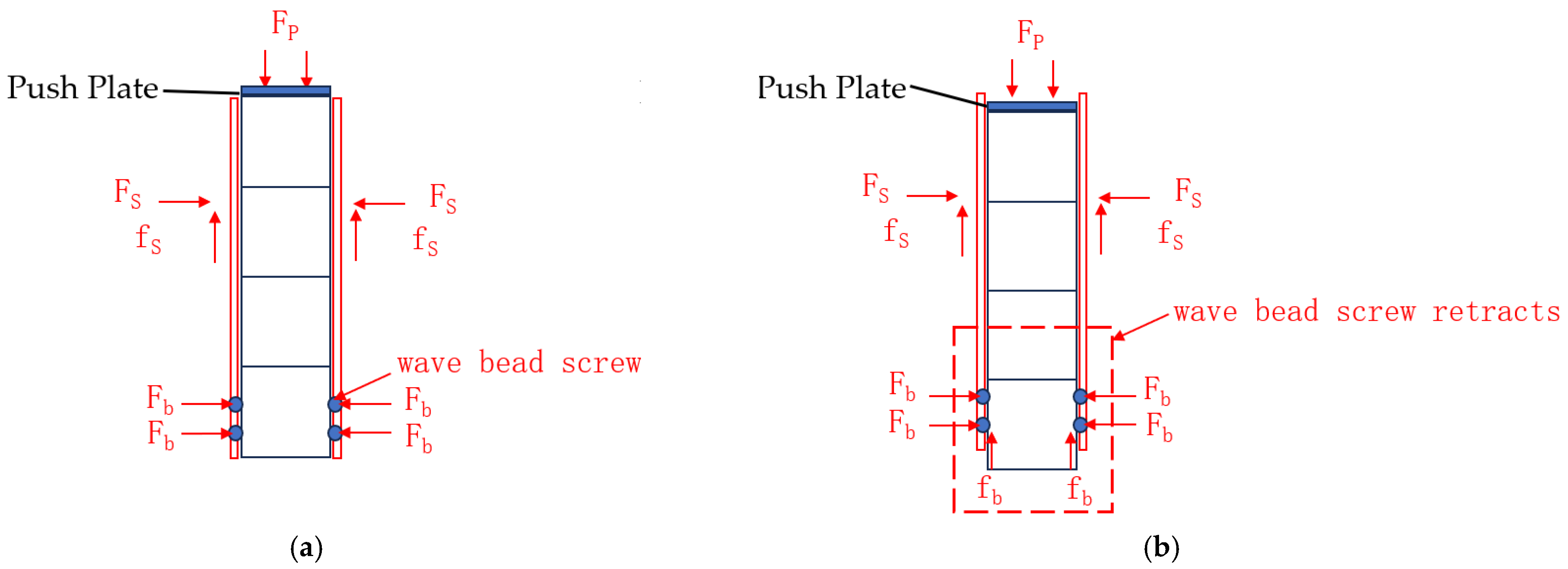
4.3. Influence of the Wave Bead Screw on the Push Attitude of a CubeSat

The compressive spring inside a wave bead screw exerts a force that temporarily locates and maintains the position of the CubeSat. Once the push force exceeds the resistive force exerted by the wave bead screw’s spring, the CubeSat is pushed onto the transport pallet. Multiple wave bead screws allow the CubeSat to resist external forces but also affect its attitude during the pushing process. As shown in Figure 19, how the number of wave washers affects the CubeSat’s attitude during the push is analyzed. Each CubeSat is assumed to have a mass of 1 kg, and no gravity is involved, with a constant force of 100 N applied downward by the push panel along the negative y-axis. Other major parameters are set as per Table 4. The process of pushing the CubeSat is illustrated in Figure 20. Initially stacked together, the lower red CubeSat is fixed by wave bead screws and will be pushed onto the transport pallet under the combined effects of the push panel and the purple CubeSat.
The symmetrical arrangements of four and eight wave bead screws are analyzed. Figure 21 illustrates the change in the y-axis position coordinates of the lower CubeSat following deployment. Each CubeSat has the dimensions 100 mm × 100 mm × 100 mm. The pushing time is about 2.4 s for four wave bead screws and 2.6 s for eight wave bead screws. The velocity of the lower CubeSat along the y-axis in both configurations is shown in Figure 22. Considering the condition of the CubeSat within the pushing device, it can be deduced that the maximum speed is about 98.4 mm/s with four wave bead screws and approximately 71.4 mm/s with eight wave bead screws. The average speeds of the two configurations are relatively close, but the second configuration has smaller velocity fluctuations. The angular speed around the z-axis of the lower CubeSat is shown in Figure 23. From the images, the maximum angular speed for the first configuration is approximately 35 °/s; for the second configuration, the angular speed remains below 20 °/s during the pushing process and is typically around 15 °/s at separation. The second configuration offers more stable performance. It causes less impact on the transport pallet after pushing and allows the CubeSat to enter the pallet more accurately with reduced disturbance during the process.
It can be observed that when using four wave bead screws, the system’s pushing speed is higher than that of eight wave bead screws. However, due to larger fluctuations in both velocity and angular velocity, sudden large angular velocities are produced, which are disadvantageous for the CubeSat’s interface with the transport pallet. This is primarily caused by the asymmetrical forces acting on the CubeSat. The use of eight wave bead screws is a slower push, but the overall process is smoother. When used in the same way as four wave bead screws, it produces less angular velocity and is more suitable for docking with transport pallets.

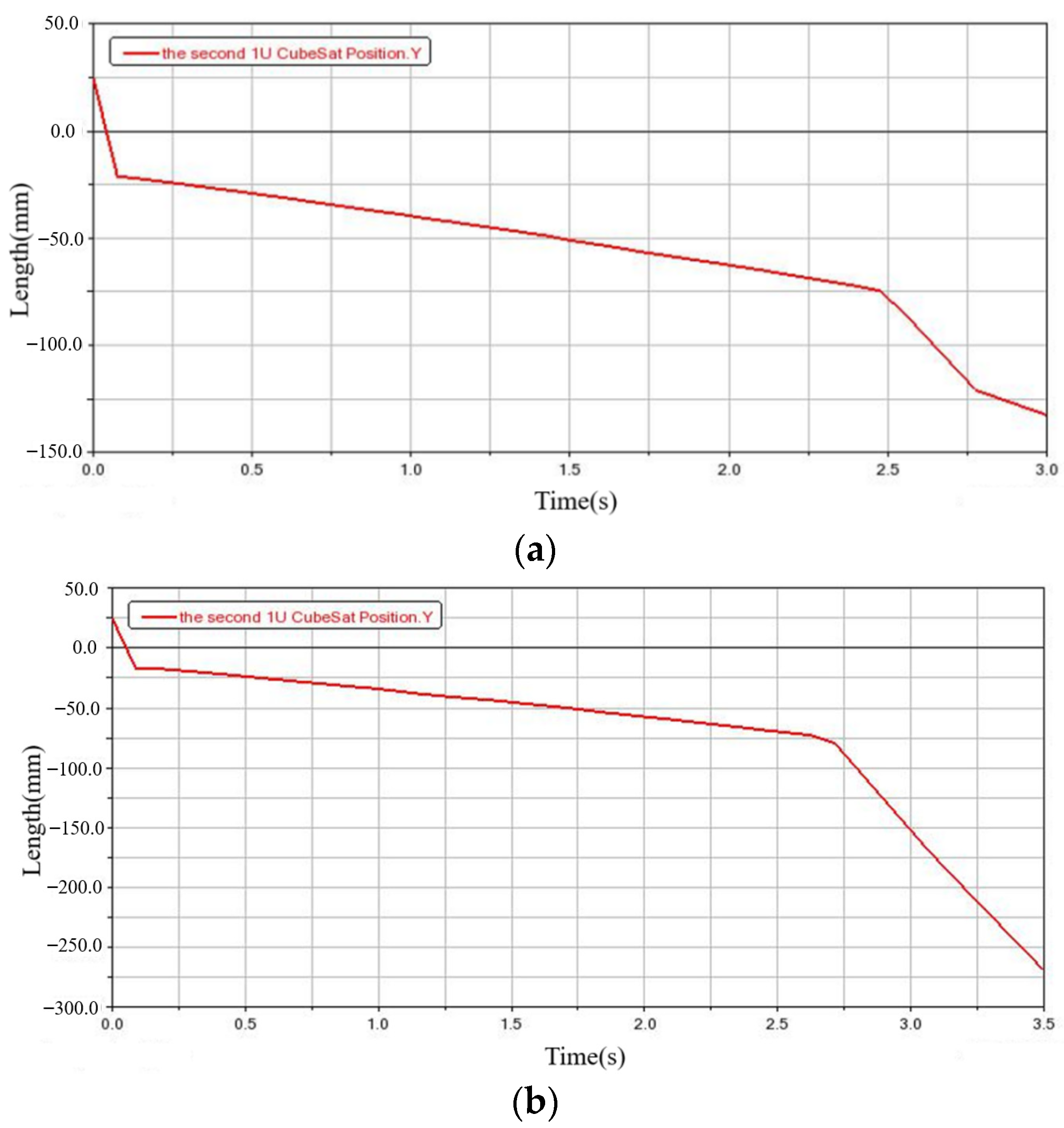
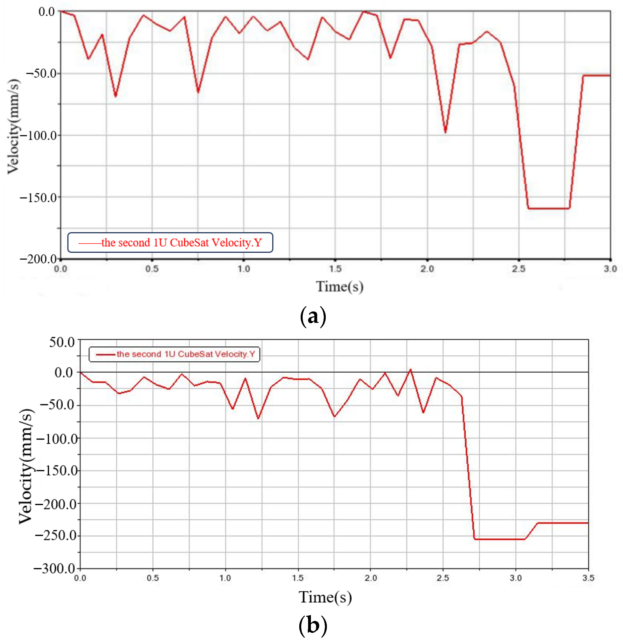
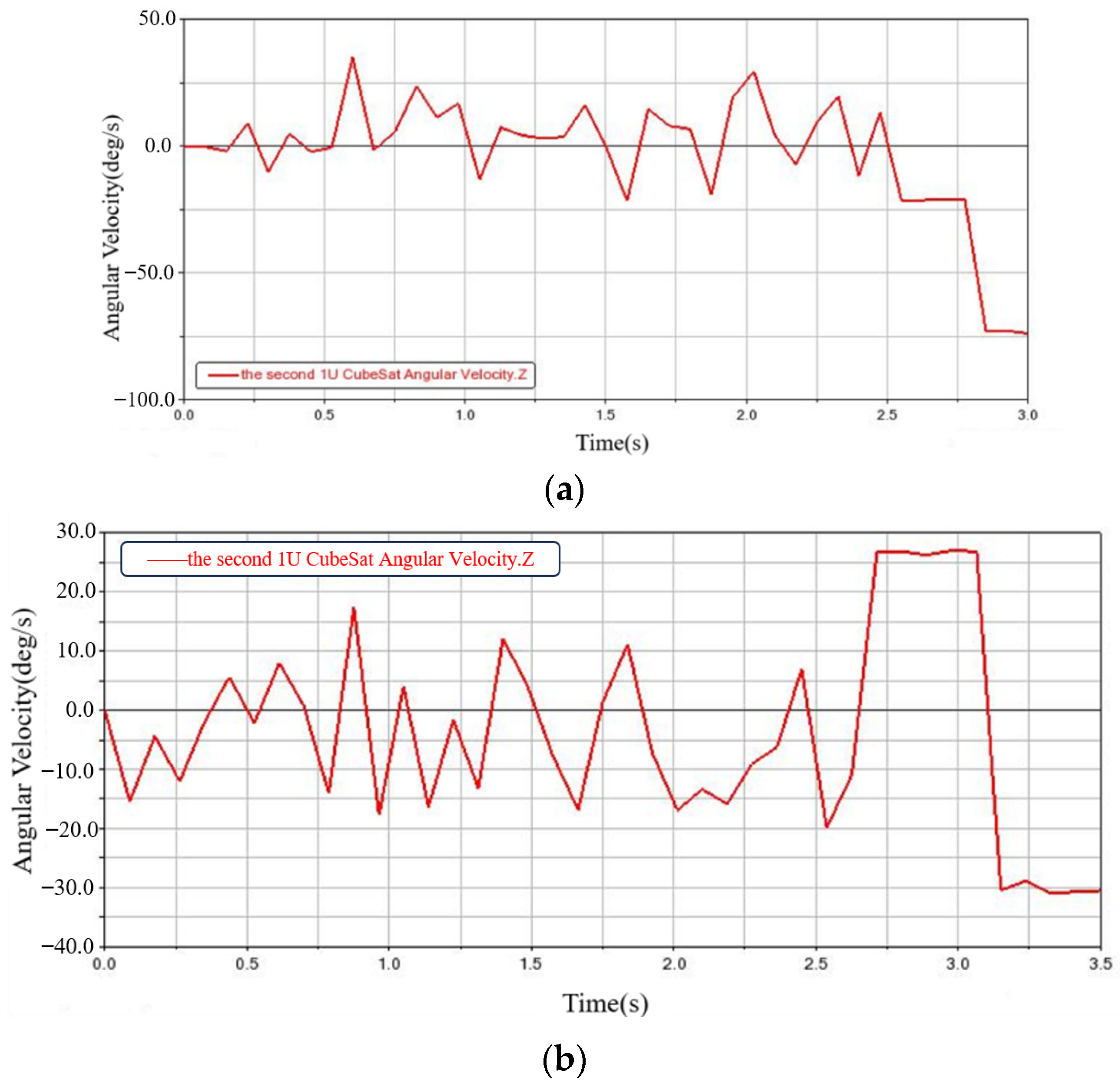
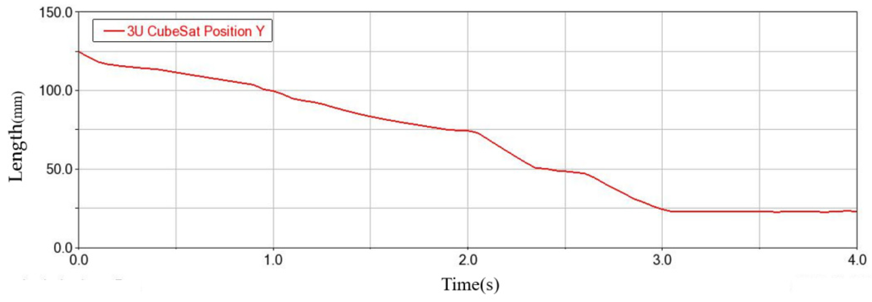
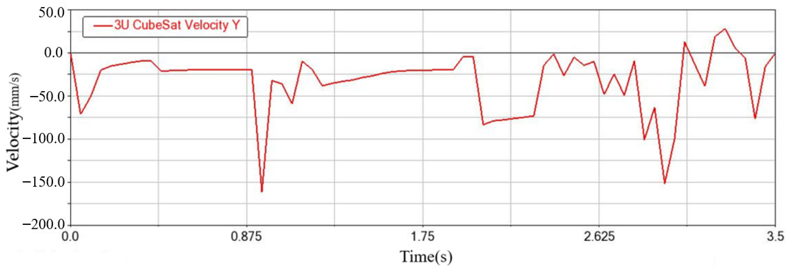
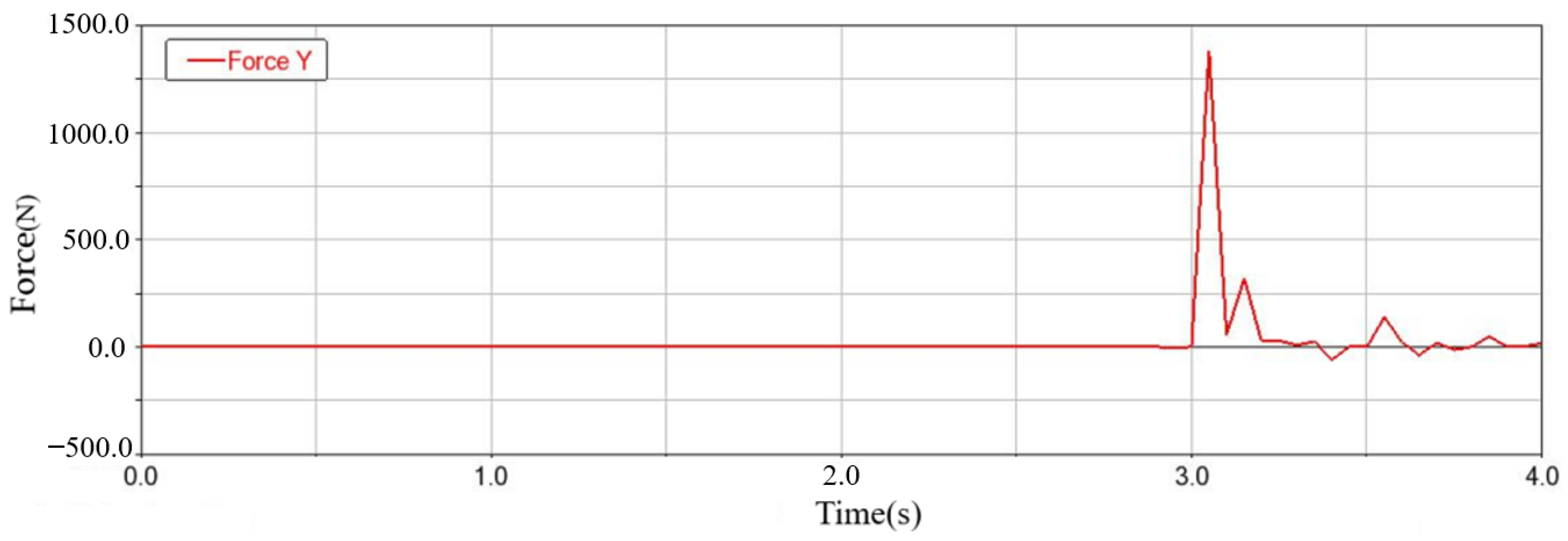
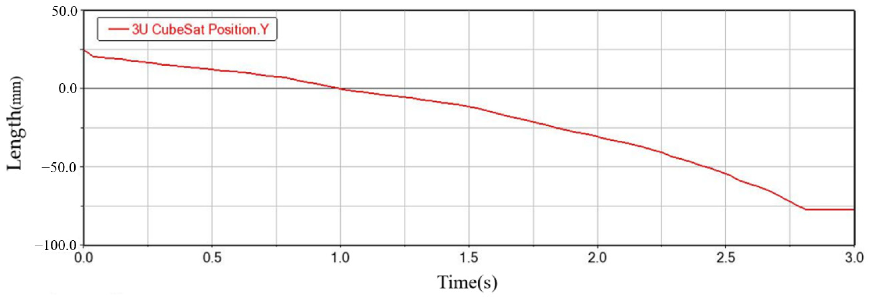
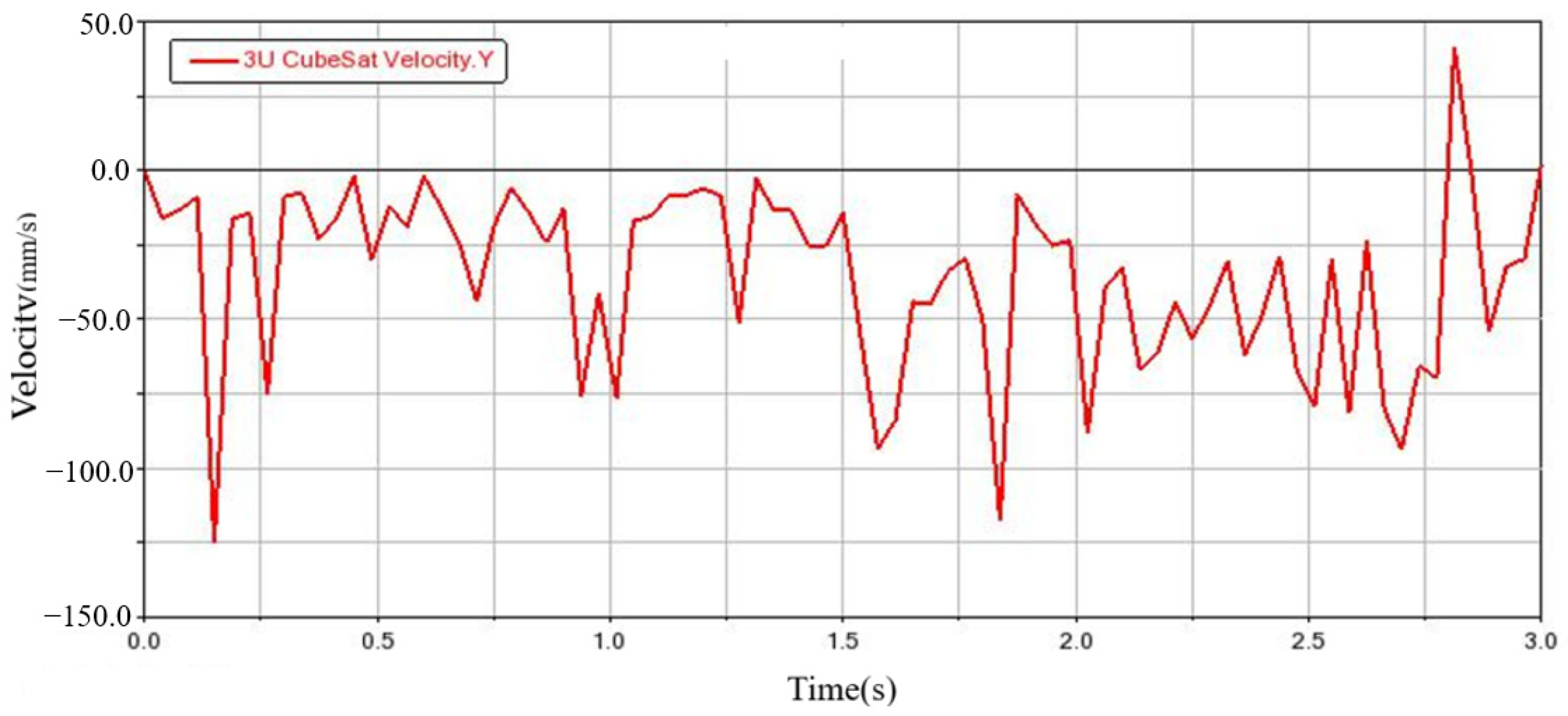
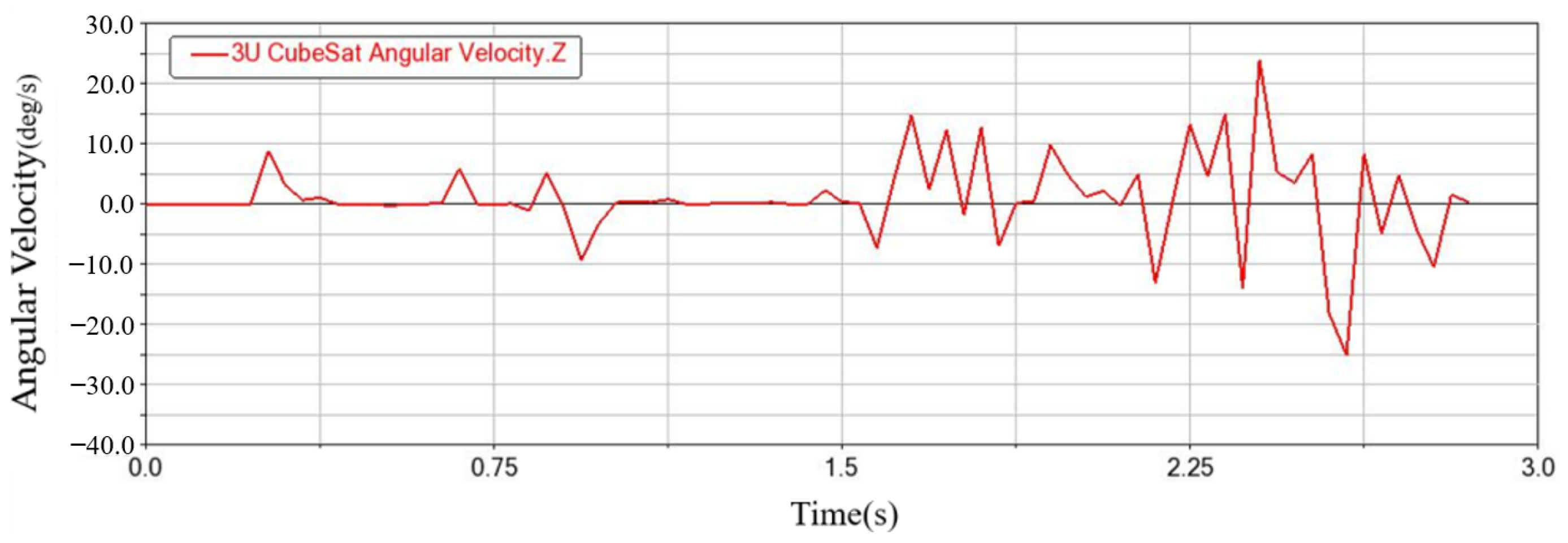
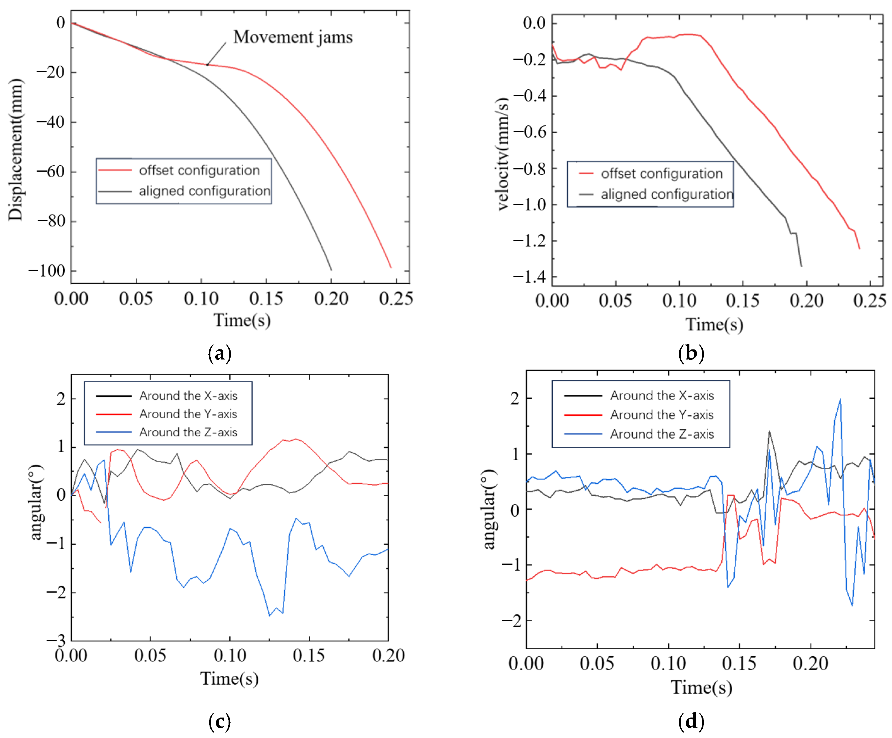
4.4. CubeSat Entry Transport Pallet Attitude Analysis

A comprehensive dynamic simulation of the entire pushing process is performed to analyze the collision dynamics between the CubeSat and the transport pallet, as well as any positional deviations experienced by the CubeSat when entering the transport pallet. The established model, as depicted in Figure 24, operates under zero-gravity conditions. Specifically, the model is as follows:
  • A 1U configuration CubeSat is assumed to have a mass of 1.3 kg.
  • A 2U configuration CubeSat is assumed to have a mass of 2.6 kg.
  • A 3U configuration CubeSat has a mass of 4 kg.
  • The static friction coefficient between the CubeSat and the transport pallet is set to 0.36.
  • The dynamic friction coefficient is 0.3.
  • All other parameters align with those specified in Table 2.
  • The push force remains directed along the negative y-axis.
The dynamic simulation of the complete pushing process reveals that CubeSats can be smoothly pushed onto the transport pallet. The motion and force characteristics are similar for both CubeSats. Taking the 3U CubeSat as an example, the simulation results are analyzed.
First, the push process for the first layer of CubeSats is simulated. The position change along the y-axis is shown in Figure 25, which indicates that it takes approximately 3.05 s to push the CubeSat to its designated position.
The velocity of the pushed CubeSat along the y-axis is shown in Figure 26. The speed of the CubeSat fluctuated during the pushing process due to the influence of the wave bead screws and the gap. Due to the high pushing speed, the CubeSat bounced upwards when it initially touched the bottom of the transport pallet and quickly returned to its original position, eventually remaining stable, with an average speed of approximately 32.8 mm/s.
The angular velocity and angular acceleration of the pushed CubeSat along the three axes are shown in Figure 27 and Figure 28. From these images, it is evident that the CubeSat begins to exhibit significant angular fluctuations around 2.1 s, before which the fluctuations are smaller. This is caused by the gradual removal of the CubeSat from the pushing device into the transport pallet, where the force is no longer uniform. The maximum angular velocity across all axes does not exceed ±15 °/s, and both the angular velocity and angular acceleration peak at positions nearing the completion of the push. The relatively small magnitude of these values indicates a stable attitude throughout the motion.
This paper analyzes the force between the CubeSat and the transport pallet. The forces along the y-axis direction and along the x-axis and z-axis directions are shown in Figure 29 and Figure 30, respectively. The results indicate that upon contact with the transport pallet’s bottom surface, a vertical impact force of approximately 1200 N is generated. This force quickly diminishes into minor fluctuations afterward.
In comparison, the horizontal forces along the x- and z-axes are relatively small, below 10 N, and remain negligible for the first 3 s. This indicates minimal horizontal displacement of the CubeSat during its motion, resulting in minimal impact on the transport pallet’s sides. The precise positioning of the CubeSat within the transport pallet is evident from these findings.
From the overall working principle of the CubeSat in-orbit transport system, it can be seen that the first layer of the CubeSats is pushed to the transport pallet, and will be transported to the release window release under the action of the two-dimensional electromagnetic transport platform. At this time, the push device temporarily stops working, and the second layer of CubeSats are static with the role of the wave bead screws. After the transport pallet is returned to the bottom of the push device, waiting for the next round of pushing, the system state is as shown in Figure 31.
After that, the second layer of CubeSats is pushed, and the position coordinate change of CubeSats along the y-axis direction is obtained, as shown in Figure 32. Additionally, the time taken to push these to the specified position is about 2.88 s.
The velocity of a CubeSat along the y-axis is shown in Figure 33. The trend of the speed changes is consistent with that observed during the first layer’s push. Due to fewer numbers of CubeSats being pushed, the average pushing speed is approximately 35.1 mm/s, slightly higher than the first layer’s 32.8 mm/s.
Analysis of a CubeSat’s axial acceleration and angular acceleration is conducted, as shown in Figure 34 and Figure 35. Compared to the motion state of a first-layer CubeSat during deployment, a second-layer CubeSat exhibits slightly larger angular velocity fluctuations. The angular velocity and angular acceleration exhibit notable changes as the CubeSat approaches its final position, with the maximum absolute angular velocity being less than 25 degrees per second. Consequently, the CubeSat’s motion process is slightly less stable than that of the first layer, but overall remains relatively stable.
Analysis of the interaction forces between a second-layer CubeSat and the platform is conducted, as shown in Figure 36 and Figure 37. From the figures, it is observed that a peak force of approximately 1200 N is generated when the CubeSat reaches the bottom of the platform, followed by minor fluctuations. The forces in the horizontal x-axis and z-axis directions are consistently less than or equal to 130 N, with a notable −190 N anomaly occurring around the 1.6 s mark. In the vertical direction, forces are only observed after the CubeSat reaches the platform’s bottom, aligning with general expectations. In the horizontal direction, force magnitudes exhibit fluctuations, which differ from the first layer of CubeSats’ deployment state. This indicates that the CubeSat experiences multiple collisions with the platform’s sides during its motion. The curves eventually stabilize, indicating that these collisions do not hinder system performance, allowing the CubeSat to successfully settle in the center of the platform.
From the dynamic simulation analysis of the CubeSat deployment process, it is evident that when stacking two CubeSats, the pushing speed is slightly slower compared to deploying a single layer, due to the presence of force loss during energy transmission to the lower layer. In systems with only one CubeSat remaining, the push plate directly applies force to the CubeSat, resulting in a higher velocity. However, both scenarios demonstrate stable platform interaction, with the CubeSats successfully entering the designated positions on the platform. The motion process remains relatively smooth, and the pushing speed is fast, with each CubeSat being pushed into place within 3.5 s.

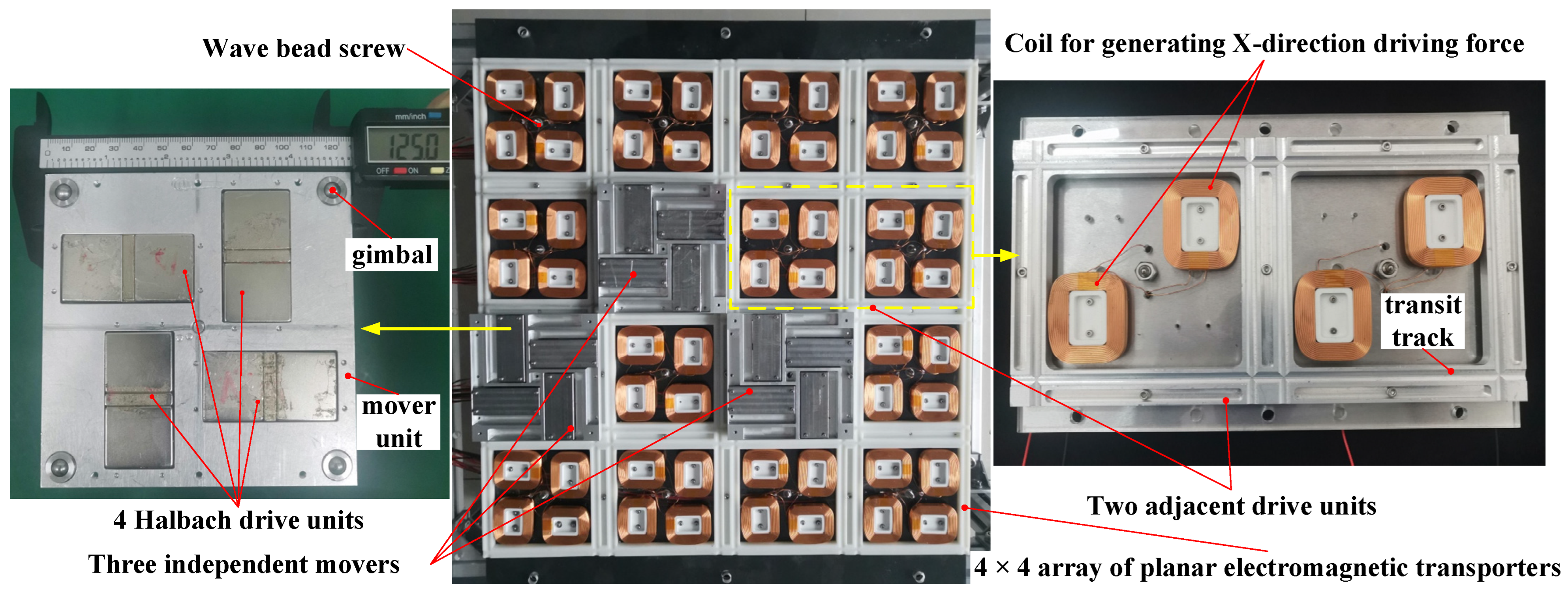
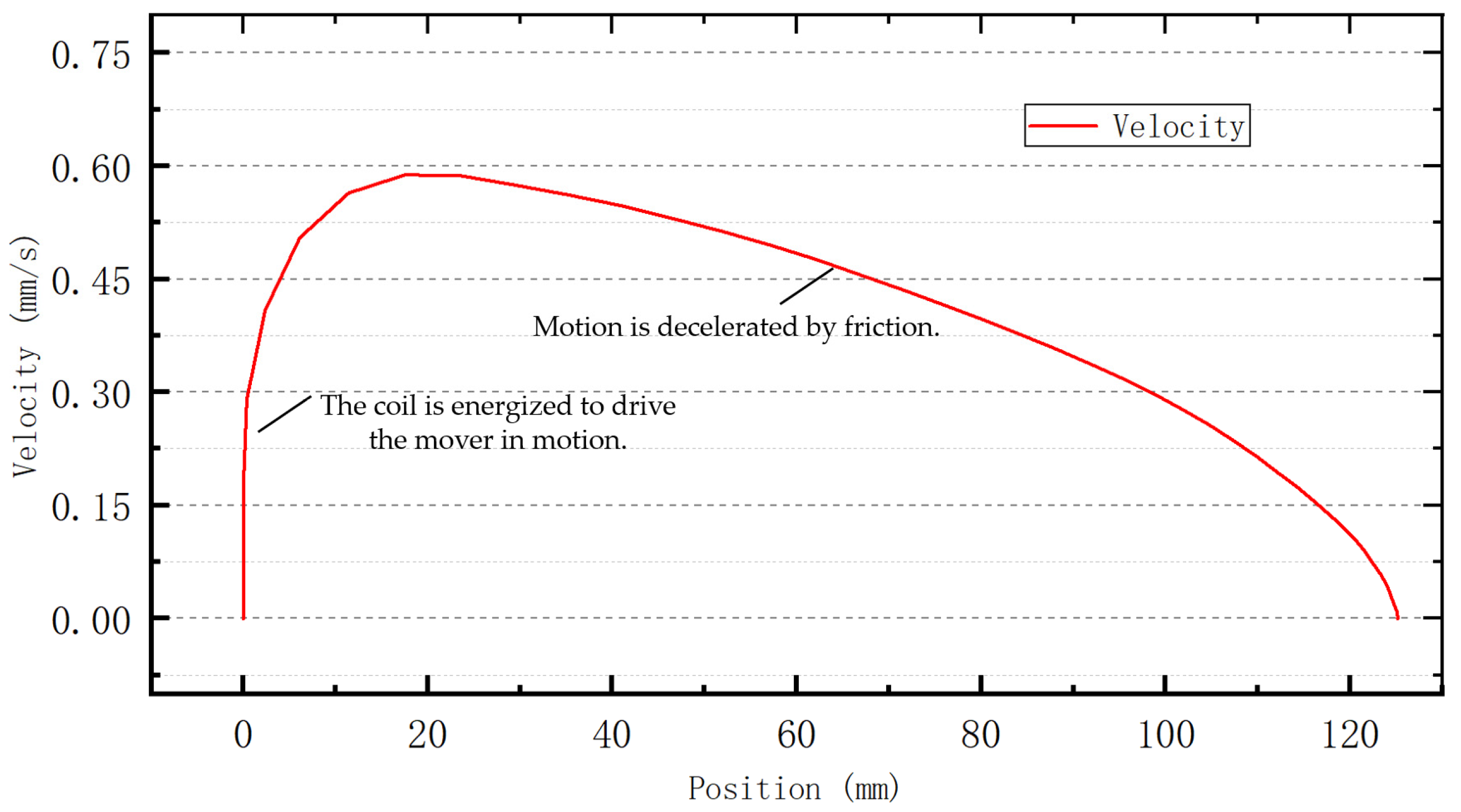
5. Experiment Investigation

Figure 38 shows a prototype of the transit system. Figure 39 shows the simulated CubeSat deployment process test experiment. Compared with the 1U CubeSat, the 3U CubeSat has a larger aspect ratio and is more prone to jamming during deployment. Therefore, it was selected as the research subject, and an optical motion capture system was employed to record the position and orientation of the simulated 3U CubeSat during the deployment process. Considering that three non-collinear marker points can reflect rigid body pose information, three spherical targets were fixed on the lateral surface of the simulated CubeSat using screws. These targets are coated with reflective materials, providing high reflection properties. In principle, two cameras can capture the position of targets on the CubeSat to obtain their pose information. To avoid issues such as target obstruction and loss of image data due to changes in the CubeSat’s orientation during the push device operation, a four-camera side-view shooting method was adopted. Using software from the upper computer, relative position, horizontal plane, and global coordinate system calibrations were performed to further determine the positions of the three markers and calculate their centroid before capturing pose information during the deployment process. The global coordinate system is set at the center position on the side face of the lower CubeSat. The push direction is along the negative z-axis. To prevent reflections from metal materials around the targets from affecting the camera’s ability to capture target position information, black adhesive tape was used for blocking purposes.
There is a small gap between the CubeSat storage state and the frame, which causes the CubeSat attitude to be in a biased state during the temporary storage process. To analyze the tolerance capacity of the traction device and the transport pallet, push measurement experiments were conducted on two scenarios: the initial attitude of the CubeSat aligned with the transport pallet, and the initial attitude with a bias.
Figure 40 presents measurement results for two different deployment configurations of the CubeSat. For both configurations, the pusher mechanism successfully deployed the CubeSat onto the transport pallet. In the scenario with an initial attitude offset, a collision occurred between the universal joint and the conical opening of the transport pallet’s vertical slide at 75 ms, resulting in a stall lasting approximately 50 ms. Subsequently, under the guidance of the transport pallet’s conical opening, the universal joint entered the vertical slide, allowing the CubeSat to be fully deployed onto the transport pallet. This entire process took about 0.246 s. In contrast, when the initial attitude was aligned with the transport pallet, the CubeSat was smoothly deployed onto the transport pallet in approximately 0.2 s. The initial velocities were relatively low in both cases due to friction generated by the compression of the wave bead screw spring on the CubeSat during the deployment process. Notably, the velocity approached zero when the CubeSat collided with the transport pallet in the offset configuration scenario.
After entering the transport pallet’s vertical slide, both CubeSats experienced further velocity increases due to the combined forces of the pusher mechanism and gravity.
The initial attitude of the CubeSat in the aligned configuration was 0.06°, 0.09°, and 0° about the x-, y-, and z-axes, respectively. In contrast, the CubeSat in the offset configuration had an initial attitude of 0.32°, −1.28°, and 0.5° about the x-, y-, and z-axes, respectively. The CubeSat in the aligned configuration exhibited minor attitude fluctuations during deployment due to the torques generated by the multiple wave bead screws. Upon entering the transport pallet, it underwent several collisions before reaching the bottom with final angles of 0.73°, 0.25°, and −1° about the x-, y-, and z-axes, respectively.
The CubeSat in the offset configuration had minimal attitude fluctuations before entering the transport pallet’s vertical slide. Upon entry, collisions between the universal joint and the vertical slide adjusted its attitude. It reached the bottom with final angles of 0.89°, −0.51°, and 0.47° about the x-, y-, and z-axes, respectively. This demonstrates that the deployed CubeSat in an offset configuration can passively adjust its attitude to an ideal state after entering the transport pallet’s slide. The designed deployment mechanism and receiving transport pallet exhibit a degree of disturbance tolerance and robustness.
After completing the experiment on the pushing process, the plane transport process experiment is carried out to verify the feasibility of the whole process of the CubeSat high-density storage and transport device. Figure 41 shows a prototype of a 4 × 4 unit array planar electromagnetic transporter developed for this purpose. The three movers can be independently controlled. To facilitate the verification of the mover’s stable adsorption and motion performance, this paper uses a motion capture system. This paper focuses on the movement of a single mover between adjacent drive units as the research object to investigate the operational characteristics of the mover carrying a CubeSat.
A 10 cm × 10 cm × 10 cm cube weighing 1 kg was mounted on the mover to simulate the transportation of a 1U CubeSat. The mover is positioned directly above the stator coil. When the coil is energized, the mover travels to the adjacent unit until it is repositioned by the ball screw. A high-speed camera records the entire process. By identifying the marker points on the cube, the transport speed of the mover carrying the payload can be obtained, as shown in Figure 42.
The results show that under the influence of gravity, a 1U CubeSat driven by the planar electromagnetic actuator initially accelerates and then continuously decelerates due to friction. The measured speed results indicate that the mover runs smoothly with minimal fluctuations and ultimately arrives at the desired location steadily, achieving stable transportation functionality. At the beginning of the movement, the transport pallet was not disturbed by the storage device, further confirming that the storage device proposed in the paper can accurately push the CubeSat onto the transport pallet.

6. Conclusions

The text describes a new deployment system designed to handle the storage and transport of 12 CubeSats of varying sizes. This system allows for the phased delivery of these CubeSats to their launch window. The device employs a modular design approach, decomposing the motion of the CubeSats within the system into one-dimensional linear motion in the pushing mechanism and two-dimensional plane motion on the electromagnetic conveying platform. This design effectively meets the storage and release requirements for CubeSats of different configurations while also enabling larger-scale CubeSat storage through expansion. A prototype of the system has been developed, along with a push motion state measurement system, to analyze the attitude oscillations of the CubeSat during its transport process within the storage device and its pose upon entering the receiving platform. The results demonstrate that the system can deploy the bottom layer of CubeSats into the platform within 0.25 s, achieving high efficiency. Additionally, the directional deviation of the CubeSats during the pushing process does not exceed one degree, revealing the device’s resistance to interference and tolerance capabilities. The results of the transport experiments further confirm the feasibility of the pushing process of the storage device proposed in the paper. The results show that the storage device is able to reliably push the CubeSat onto the transport pallet without affecting the subsequent transport process.
This paper describes how the high-density storage and transfer device for large-volume CubeSats can complete the storage of CubeSats and can push the CubeSats to the transfer pallet in the release process according to the task requirements, which proves the feasibility of the device. Restricted by the experimental site and research conditions, the current development of the prototype is only part of the verification of the whole process of storage, transfer, and release. The structure in this paper can only hold 1–3U CubeSats, with a total capacity of 24U. The type and volume of CubeSat that can be held now are better than those of current mainstream CubeSat deployers. At the same time, unlike conventional CubeSat deployers, the CubeSat storage device proposed in this paper can accommodate different types of CubeSats according to different tasks, and the number of stacked CubeSats can be easily increased to expand the device to realize the storage and transfer of larger-sized and larger-capacity CubeSats. The proposed CubeSat storage device increases the density of CubeSats and reduces the additional mass by separating the stacked CubeSats with a simple push mechanism. This is an essential structural difference from current CubeSat deployers that store a single CubeSat in a single compartment. Experimental results have demonstrated that this shift is a good way to increase the density and variety of storage.

Author Contributions

Conceptualization, Y.Z. (Yong Zhao) and Y.Z. (Yuhao Zhang); methodology, L.Z. and X.Y.; software, C.H. and J.Z.; validation, Y.e.H. and Y.W.; formal analysis, G.X.; investigation, Z.Z. and X.Y.; resources, Y.Z. (Yuhao Zhang); data curation, Z.Z., C.H. and J.Z.; writing—original draft preparation, Y.W. and M.K.; writing—review and editing, C.L., Y.e.H. and G.X.; visualization, Y.Z. (Yuhao Zhang), Z.Z., C.L. and X.Y.; supervision, L.Z. and H.Y.; project administration, Y.Z. (Yong Zhao); funding acquisition, Y.Z. (Yong Zhao) and H.Y. All authors have read and agreed to the published version of the manuscript.

Funding

This work was supported by the Foundation of Chinese State Key Laboratory of Robotics and Systems (Grant No. SKLRS202413B), the Foundation of National Key Laboratory of Aerospace Mechanism, China (Grant No. 2024ASH-ZY05), the National Natural Science Foundation of China (Grant No. 52405257), the China Postdoctoral Science Foundation (Grant No. 2024M764201), the Postdoctoral Fellowship Program (Grade B) of China Postdoctoral Science Foundation (Grant No. GZB20240955), the Natural Science Foundation of Heilongjiang Province, China (Grant No. LH2024E029), and the Heilongjiang Postdoctoral Science Foundation (Grant No. LBH-Z24184).

Institutional Review Board Statement

Not applicable.

Data Availability Statement

The original contributions presented in this study are included in the article.

Acknowledgments

The author would like to thank the editors, academic editor, and the reviewers for their valuable comments and constructive suggestions that helped to improve the paper significantly.

Conflicts of Interest

Author Lili Zhang was employed by the company Harbin Space Star Data System Technology Co., Ltd. The remaining authors declare that the research was conducted in the absence of any commercial or financial relationships that could be construed as a potential conflict of interest.

References

  1. Bao, W.M.; Wang, X.W. Develop high reliable and low-cost technology of access to space, embrace new space economy era. China Aerosp. 2019, 20, 23–30. [Google Scholar]
  2. Kutter, B.F.; Sowers, G.F.; Cislunar, F. Transportation supporting a self-sustaining space economy. In Proceedings of the AIAA SPACE 2016, Long Beach, CA, USA, 13–16 September 2016. [Google Scholar]
  3. Lombardo, M.; Zannoni, M.; Gai, I.; Casajus, L.G.; Gramigna, E.; Manghi, R.L.; Tortora, P.; Di Tana, V.; Cotugno, B.; Simonetti, S.; et al. Design and analysis of the cis-lunar navigation for the Argo moon CubeSat mission. Aerospace 2022, 9, 659. [Google Scholar] [CrossRef]
  4. Bouwmeester, J.; Guo, J. Survey of worldwide pico- and nanosatellite missions, distributions and subsystem technology. Acta Astronaut 2010, 67, 854–862. [Google Scholar] [CrossRef]
  5. Poghosyan, A.; Golkar, A. CubeSat evolution: Analyzing CubeSat capabilities for conducting science missions. Prog. Aerosp. Sci. 2017, 1, 59–83. [Google Scholar] [CrossRef]
  6. Saeed, N.; Elzanaty, A.; Almorad, H.; Dahrouj, H.; Al-Naffouri, T.Y.; Alouini, M.-S. CubeSat communications: Recent advances and future challenges. IEEE Commun. Surv. Tutor. 2020, 22, 1839–1862. [Google Scholar] [CrossRef]
  7. Toorian, A.; Diaz, K.; Lee, S. The CubeSat approach to space access. In Proceedings of the IEEE Aerospace Conference, Big Sky, MT, USA, 1–8 March 2008; Volume 5, pp. 1–14. [Google Scholar]
  8. Nason, I.; Puig-Suari, J.; Twiggs, R. Development of a family of picosatellite deployers based on the CubeSat standard. In Proceedings of the IEEE Aerospace Conference, Big Sky, MT, USA, 9–16 March 2002; p. 1. [Google Scholar]
  9. Dobrowolski, M.; Grygorczuk, J.; Kedziora, B.; Tokarz, M.; Borys, M. Dragon—8u nanosatellite orbital deployer. In Proceedings of the 42nd Aerospace Mechanisms Symposium, Baltimore, MD, USA, 14–16 May 2014; pp. 1–10. [Google Scholar]
  10. Johnson, M.D. Satellite Deployer System i.e., CubeSat Deployer for Use in the Field of Space Transportation, Has Ejector Mechanism That Pushes or Pulls Satellite Out of Receptacle, Where Satellite Is Deployed from Launch Vehicle by Ejector Mechanism After Releasable Mechanism Is Released. US2023348116-A1, 2 November 2023. [Google Scholar]
  11. Mohamed, R. Design and Implementation of Ground Support Equipment for Characterizing Performance of XPOD and CNAPS & Thermal Analysis of CNAPS Pressure Regulator Valve. Ph.D. Thesis, University of Toronto, Toronto, ON, Canada, 2009. [Google Scholar]
  12. Pranajaya, F.M.; Zee, R.E. The generic nanosatellite bus: From space astronomy to formation flying demo to responsive space. In Proceedings of the International Conference on Advances in Satellite and Space Communications, Siena-Tuscany, Italy, 10–11 September 2009; pp. 134–140. [Google Scholar]
  13. Wu, H.; Wang, D.; Zhang, X.; Zhao, C.; Wang, D. Development and inspiration of the Dutch space innovation solutions company. Space Ind. Manag. 2018, 408, 52–56. (In Chinese) [Google Scholar]
  14. Xie, C. Research on Design Analysis Method and Key Technology of Star-Arrow Separation Mechanism of Picosatellite. Doctoral Dissertation, Zhejiang University, Hangzhou, China, 2014. (In Chinese). [Google Scholar]
  15. Launch Services for Small Satellites and CubeSats. Available online: https://www.exolaunch.com/ (accessed on 5 May 2025).
  16. Zhao, Y.; Yue, H.; Yang, F.; Zhu, J. A High Thrust Density Voice Coil Actuator With a New Structure of Double Magnetic Circuits for CubeSat Deployers. IEEE Trans. Ind. Electron 2022, 69, 13305–13315. [Google Scholar] [CrossRef]
  17. Zhao, Y.; Yue, H.; Zhu, J.G.; Yang, F. Armature Reaction Analysis and Suppression of Voice Coil Actuator Based on an Improved Magnetic Equivalent Circuit Model. IEEE Trans. Ind. Electron. 2024, 71, 7599–7609. [Google Scholar] [CrossRef]
  18. Gue, K.R. Very high density storage systems. IIE Trans. 2006, 38, 79–90. [Google Scholar] [CrossRef]
  19. SpaceX. Starlink Multi-Satellite Separation System. Available online: https://www.starlink.com/ (accessed on 20 January 2025).
  20. Zhao, Y.; Yue, H.; Zhu, J.G.; Yang, X.Z. A Planar Electromagnetic Actuator With Passive Adsorption for CubeSats Transport in a Weightless Environment. IEEE Trans. Ind. Electron. 2023, 70, 10396–10407. [Google Scholar] [CrossRef]
  21. Li, F.; Niu, D.; Li, T.; Xue, Y.; Huang, X. Research and design of cloud monitoring and management system for intelligent stereo garage. J. Eng. 2019, 22, 8335–8338. [Google Scholar] [CrossRef]
  22. Brezovnik, S.; Gotlih, J.; Balič, J.; Gotlih, K.; Brezočnik, M. Optimization of an automated storage and retrieval systems by swarm intelligence. Procedia Eng. 2015, 100, 1309–1318. [Google Scholar] [CrossRef]
  23. Nils, B.; Konrad, S. A survey on single crane scheduling in automated storage/retrieval systems. Eur. J. Oper. Res. 2016, 254, 691–704. [Google Scholar]
  24. Carlo, H.J.; Iris, F.A.; Vis, B. Sequencing dynamic storage systems with multiple lifts and shuttles. Int. J. Prod. Econ. 2012, 140, 844–853. [Google Scholar] [CrossRef]
  25. Ekren, B.Y.; Heragu, S.S. Simulation based performance analysis of an autonomous vehicle storage and retrieval system. Simul. Model. Pract. Theory 2011, 19, 1640–1650. [Google Scholar] [CrossRef]
  26. Kallo, N.; Koltai, T. Increasing customer satisfaction in queuing systems with rapid modelling. In Rapid Modelling and Quick Response; Springer Nature: London, UK, 2010; pp. 119–130. [Google Scholar]
  27. Zielinski, A.E.; Delguercio, M.A. Analytical study of the injection of a moving projetile into a railgun. IEEE Trans. Plasma Sci. 2011, 39, 235–240. [Google Scholar] [CrossRef]
  28. Bai, T.; Kong, L.; Huang, J.; Jiang, F.; Zhang, L. Thermal design and verification of micro remote-sensing satellite in low inclination orbit. Opt. Precis. Eng. 2020, 28, 2497–2506. (In Chinese) [Google Scholar] [CrossRef]
Figure 1. Macro workflow of the CubeSat storage device.
Aerospace 12 00466 g001
Figure 2. Structure of wave bead screw.
Aerospace 12 00466 g002
Figure 3. Overall flow of the transport and release process of CubeSats. (a) Initial state (front view); (b) push the CubeSats to the transport pallet (front view); (c) transport to the release window (vertical view); (d) ejection of CubeSats (vertical view).
Aerospace 12 00466 g003
Figure 4. Flow chart of CubeSat transport and release.
Aerospace 12 00466 g004
Figure 5. The whole process of transporting and releasing CubeSats. (a) Initial state of the device; (b) transport CubeSat in transport pallet; (c) after transport to the designated location, the CubeSat is released; (d) transport pallet return; (e) pushing the CubeSat; (f) continued transport of the CubeSat in the transport pallet.
Aerospace 12 00466 g005
Figure 6. Overall model of the CubeSat storage device.
Aerospace 12 00466 g006
Figure 7. Side panel structure of the CubeSat storage device.
Aerospace 12 00466 g007
Figure 8. The shape structure of a CubeSat.
Aerospace 12 00466 g008
Figure 9. Structure of the transport pallet.
Aerospace 12 00466 g009
Figure 10. Initial state of the push device (front view).
Aerospace 12 00466 g010
Figure 11. Top view of the push plate assembly.
Aerospace 12 00466 g011
Figure 12. Partial structure of the push device (side view).
Aerospace 12 00466 g012
Figure 13. Front view of the push process of CubeSats. (a) Initial state of the device; (b) the state of the device after the push is complete.
Aerospace 12 00466 g013
Figure 14. Shapes of vibration for modal analysis of devices. (a) First-order modal shapes; (b) sixth order modal shapes.
Aerospace 12 00466 g014
Figure 15. Thermal strain contour plot of the device. (a) Ambient temperature 60 °C; (b) ambient temperature −30 °C.
Aerospace 12 00466 g015
Figure 16. Simplified structure of the push device.
Aerospace 12 00466 g016
Figure 17. Force analysis diagram of the push plate.
Aerospace 12 00466 g017
Figure 18. Force analysis of the CubeSat storage device in different states. (a) Force analysis of the CubeSat in the storage state; (b) force analysis of the CubeSat in the push state.
Aerospace 12 00466 g018
Figure 19. Simulation structure of the CubeSat storage device.
Aerospace 12 00466 g019
Figure 20. Front view of the simulation of the CubeSat pushing process.
Aerospace 12 00466 g020
Figure 21. Displacement image of the bottom CubeSat in the y-axis direction. (a). Four wave bead screws; (b). eight wave bead screws.
Aerospace 12 00466 g021
Figure 22. Velocity image of the underlying CubeSat in the y-axis direction. (a). Four wave bead screws; (b). eight wave bead screws.
Aerospace 12 00466 g022
Figure 23. Angular velocity images of the underlying CubeSat around the z-axis. (a). Four wave bead screws; (b). eight wave bead screws.
Aerospace 12 00466 g023
Figure 24. Initial state of the push process simulation (front view).
Aerospace 12 00466 g024
Figure 25. Displacement image of the first-layer CubeSat in the y-axis direction.
Aerospace 12 00466 g025
Figure 26. Velocity image in the y-axis direction of the first CubeSat layer.
Aerospace 12 00466 g026
Figure 27. Triaxial angular velocity image of a first-layer CubeSat.
Aerospace 12 00466 g027
Figure 28. Triaxial angular acceleration image of a first-layer CubeSat.
Aerospace 12 00466 g028
Figure 29. Force in the y-axis between the first-layer CubeSat and the transport pallet.
Aerospace 12 00466 g029
Figure 30. X- and z-axis forces between the first-layer CubeSat and the transport pallet.
Aerospace 12 00466 g030
Figure 31. The state of the new push process simulation (front view).
Aerospace 12 00466 g031
Figure 32. Displacement image in the y-axis direction of the second layer of CubeSats.
Aerospace 12 00466 g032
Figure 33. Velocity image in the y-axis direction of the second layer of the CubeSats.
Aerospace 12 00466 g033
Figure 34. Angular velocity image of a second-layer CubeSat around the z-axis.
Aerospace 12 00466 g034
Figure 35. Angular acceleration image of the second layer of CubeSats around the z-axis.
Aerospace 12 00466 g035
Figure 36. Second layer of CubeSats and transport pallet y-axis direction force.
Aerospace 12 00466 g036
Figure 37. Second layer of CubeSats and transport pallet x-axis and z-axis direction forces.
Aerospace 12 00466 g037
Figure 38. Prototype of the transit system.
Aerospace 12 00466 g038
Figure 39. Push experiment of the traction device.
Aerospace 12 00466 g039
Figure 40. Measurement results of CubeSat motion during the push process. (a) Displacement in the z-direction; (b) velocity in the z-direction; (c) angular displacement under an ideal attitude; (d) angular displacement under a bias attitude.
Aerospace 12 00466 g040
Figure 41. Research prototype of a 4 × 4 matrix planar electromagnetic actuator.
Aerospace 12 00466 g041
Figure 42. Velocity image of the motion of the mover.
Aerospace 12 00466 g042
Table 1. Performance comparison by deployer.
PerformanceDeployment SpeedSatellite CapacityModularityAutonomyVolume Efficiency
Name
P-PODThe third generation P-POD has a hatch unlock time of 45 ms
Very quickly
3ULow level of modularity and poor expandabilityAuto-releasable, higherSingle capsule to hold a single CubeSat, less volumetrically efficient
DragonCubeSat separation speed is about 1.5 m/s.
Very quickly
200 mm × 200 mm × 200 mmLow level of modularity and poor expandabilityAuto-releasable, higherSingle capsule to hold a single CubeSat, less volumetrically efficient
XPODVery quickly100 mm × 100 mm × 100 mm
100 mm × 100 mm × 300 mm
200 mm × 200 mm × 200 mm
200 mm × 200 mm × 400 mm
Low level of modularity and poor expandabilityAuto-releasable, higherSingle capsule to hold a single CubeSat, less volumetrically efficient
SPLCubeSat separation speed is about 1.4 m/s.
Very quickly
1U, 2U, 3U, and 12ULow level of modularity and poor expandabilityAuto-releasable, higherSingle capsule to hold a single CubeSat, less volumetrically efficient
RAFTSeparation speeds of 2.6 m/s and 1.2 m/s, respectively.
Very quickly
Two 1U CubeSatsLow level of modularity and poor expandabilityAuto-releasable, higherSingle capsule to hold a single CubeSat, less volumetrically efficient
ExopodDeployment velocities are calculated based on the physical properties of the mechanical springs. 1U CubeSats can be released at speeds of up to 2 m/s
Very quickly
Maximum capacity 16ULow level of modularity and poor expandabilityAuto-releasable, higherSingle capsule to hold a single CubeSat, less volumetrically efficient
StarlinkSlowlySuitable for customized satellitesRockets on board, satellites folded and stackedAuto-releasable, higherHigh storage volume efficiency
The Mengtian Experiment ModuleRelease speed not less than 1 m/sMicro-nano-satellites with dimensions less than 1000 mm × 500 mm × 700 mm and a mass of 10 kg–200 kg.Low level of modularity and poor expandabilityRequires astronaut collaboration, lowerSeparate storage in a warehouse, requiring larger storage space
Our deviceQuickly1U–3U, maximum capacity 24UCubeSat zoned stacked storage with high expandabilityAuto-releasable, higherHigh storage volume efficiency
Table 2. The first six orders of the device’s formation correspond to the intrinsic frequency.
First-Order FormationSecond-Order FormationThird-Order FormationFourth-Order FormationFive-Step FormationSixth-Order Formation
Frequency (Hz)147.71168.32269.17305.45353.4393.4
Table 3. Motor parameters.
Parameter NameParameter Value
Input voltage24 V
Rated speed80 rpm
Maximum no-load speed98 rpm
No-load current0.26 A
Rated torque14 kgf⋅cm
Extreme load torque50 kgf⋅cm
Table 4. Simulation parameters.
Parameter NameSet Point
Contact force index, n1.4
Normal embedding depth, δ0.1 mm
Bead screw spring stiffness factor, K6.25 N/mm
Coefficient of static friction between CubeSat and pusher plate and frame0.36
Coefficient of dynamic friction between CubeSat and push plate and frame0.3
Coefficient of static friction between two CubeSats1.4
Coefficient of dynamic friction between two CubeSats1.05
Disclaimer/Publisher’s Note: The statements, opinions and data contained in all publications are solely those of the individual author(s) and contributor(s) and not of MDPI and/or the editor(s). MDPI and/or the editor(s) disclaim responsibility for any injury to people or property resulting from any ideas, methods, instructions or products referred to in the content.

