
Nanosecond Laser Etching of Surface Drag-Reducing Microgrooves: Advances, Challenges, and Future Directions


Abstract
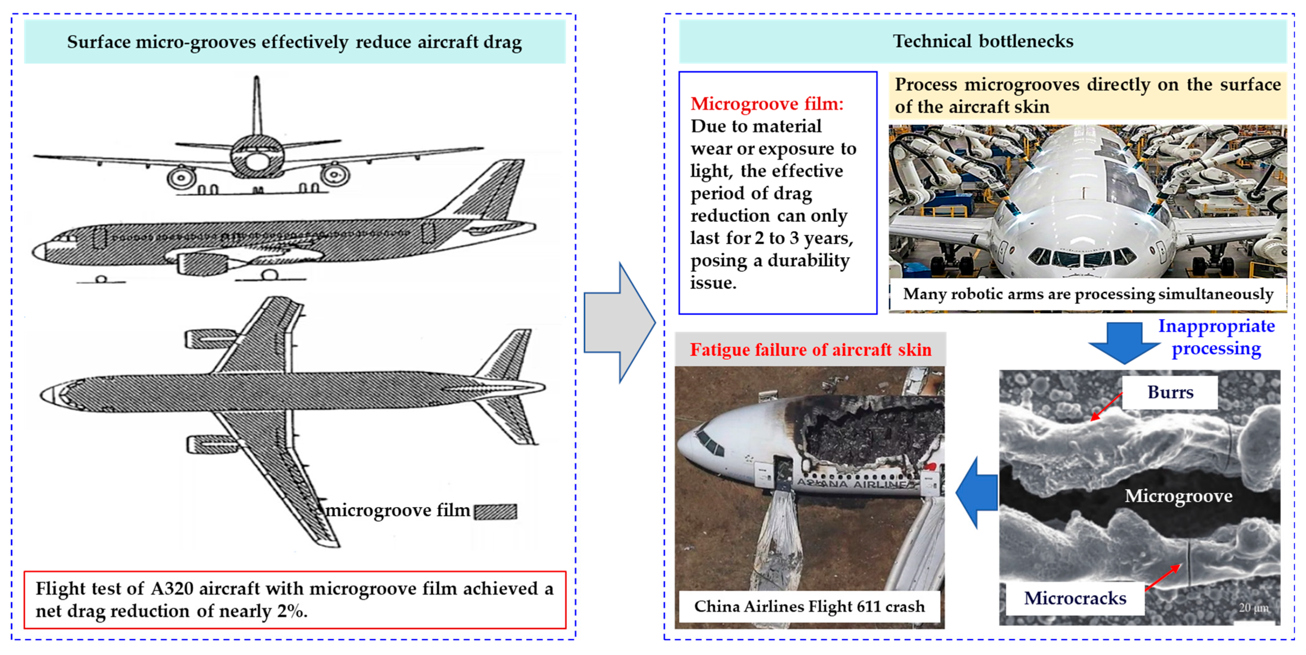
1. Introduction
2. Forming Process of Drag-Reducing Microgrooves
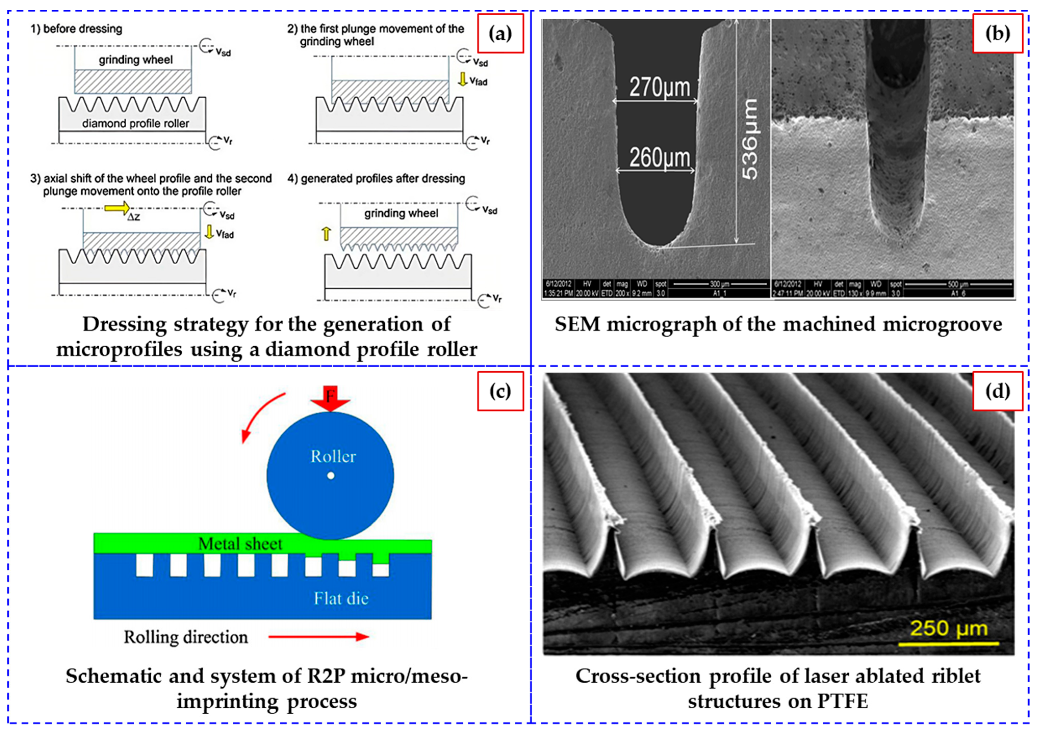
2.1. Machining of Microgrooves
2.2. Chemical Etching of Microgrooves
2.3. Rolling of Microgrooves
2.4. Laser Etching of Microgrooves

| Processing Methods | Existing Problems | References |
|---|---|---|
| Mechanical machining | Introducing residual tensile stress. | [22,23,24,25,26,27] |
| Chemical etching | Being environmentally unfriendly and lacking precision. | [28,29] |
| Roll forming | High rolling pressure may lead to plastic deformation or rebound of the skin, and the molds wear out quickly, requiring frequent replacement, which increases costs. | [30,31,32,33,34,35,36,37,38,39] |
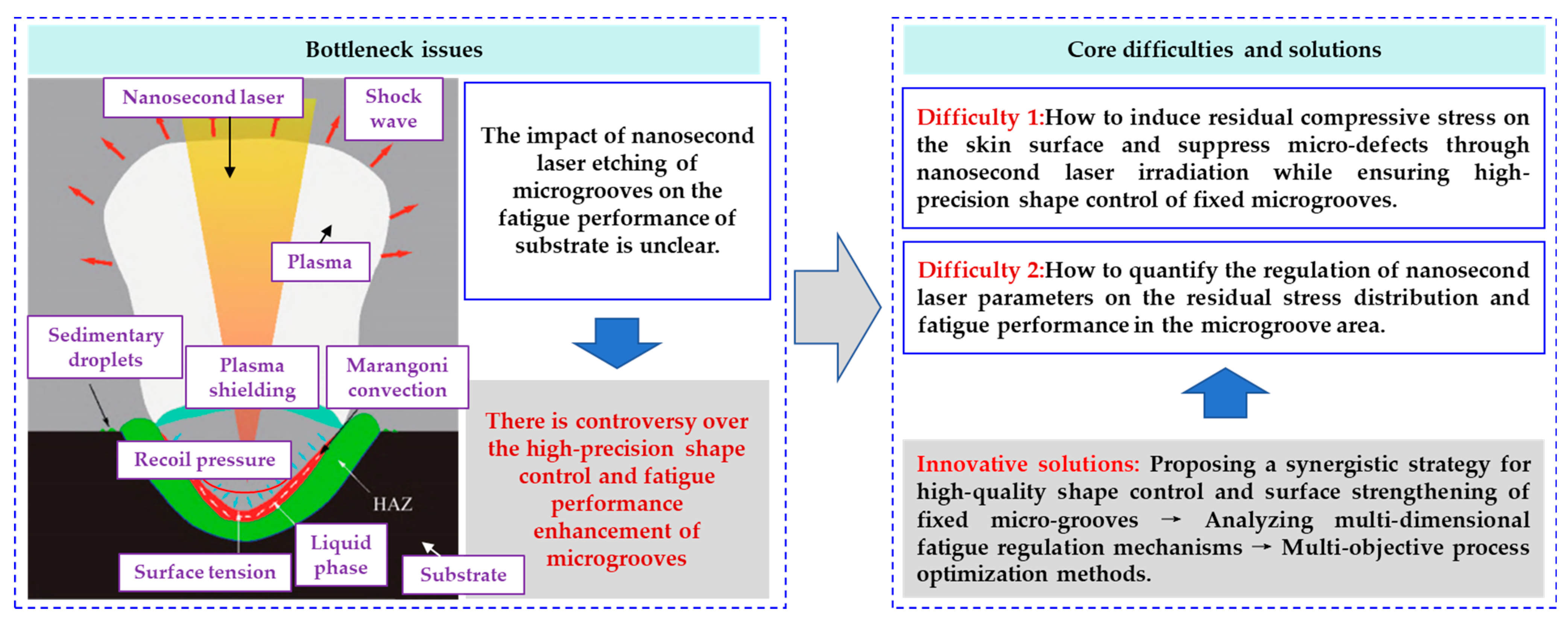
| Nanosecond laser processing | The impact of high-quality processing of fixed microgrooves on their substrate fatigue performance remains unclear. | [4,9,15,16,40,41] |
| Ultrafast laser processing | Low efficiency makes it difficult to meet the large-area processing requirements of aircraft skins. | [42,43] |
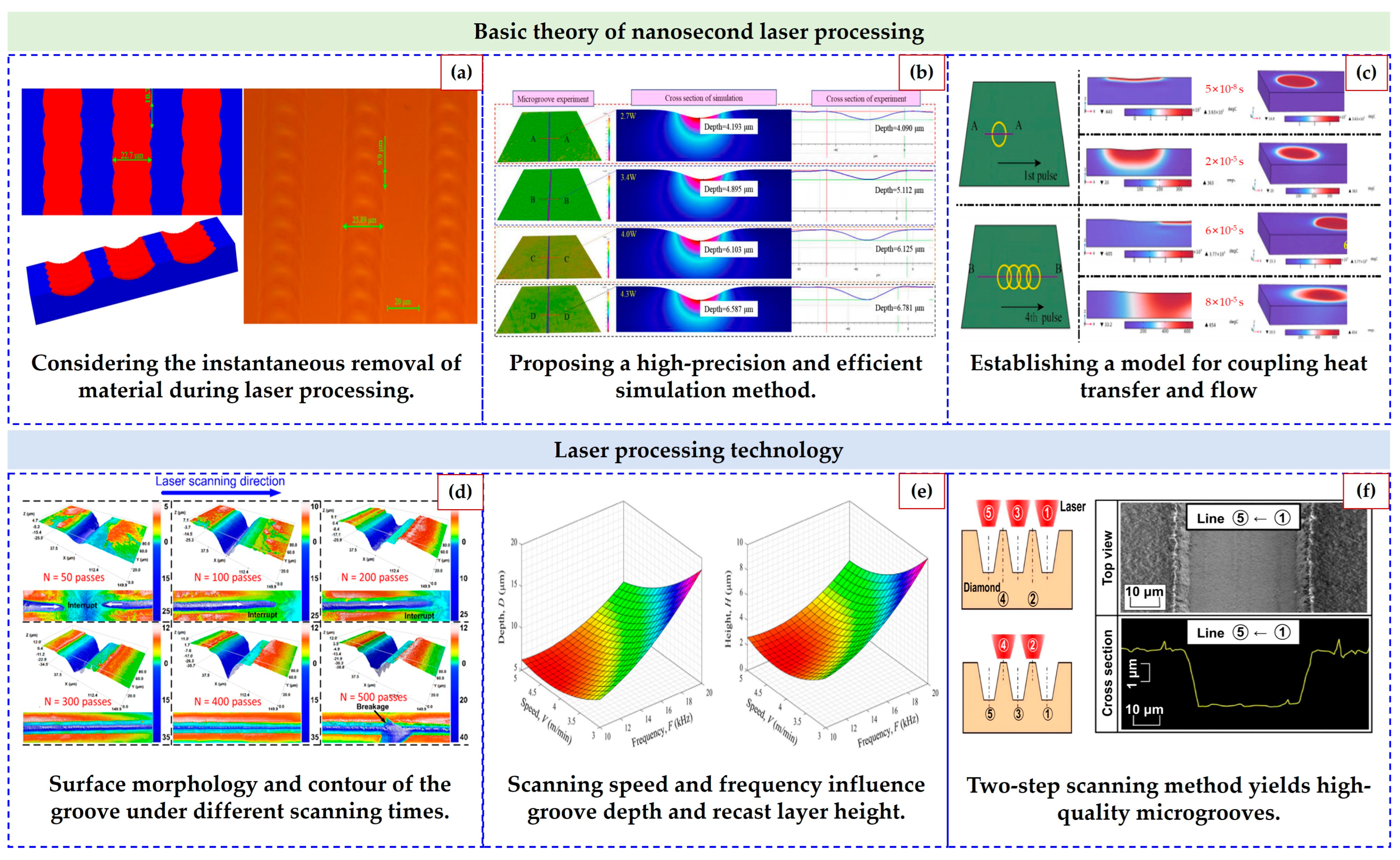
3. Quality Control of Nanosecond Laser Machining of Microgrooves
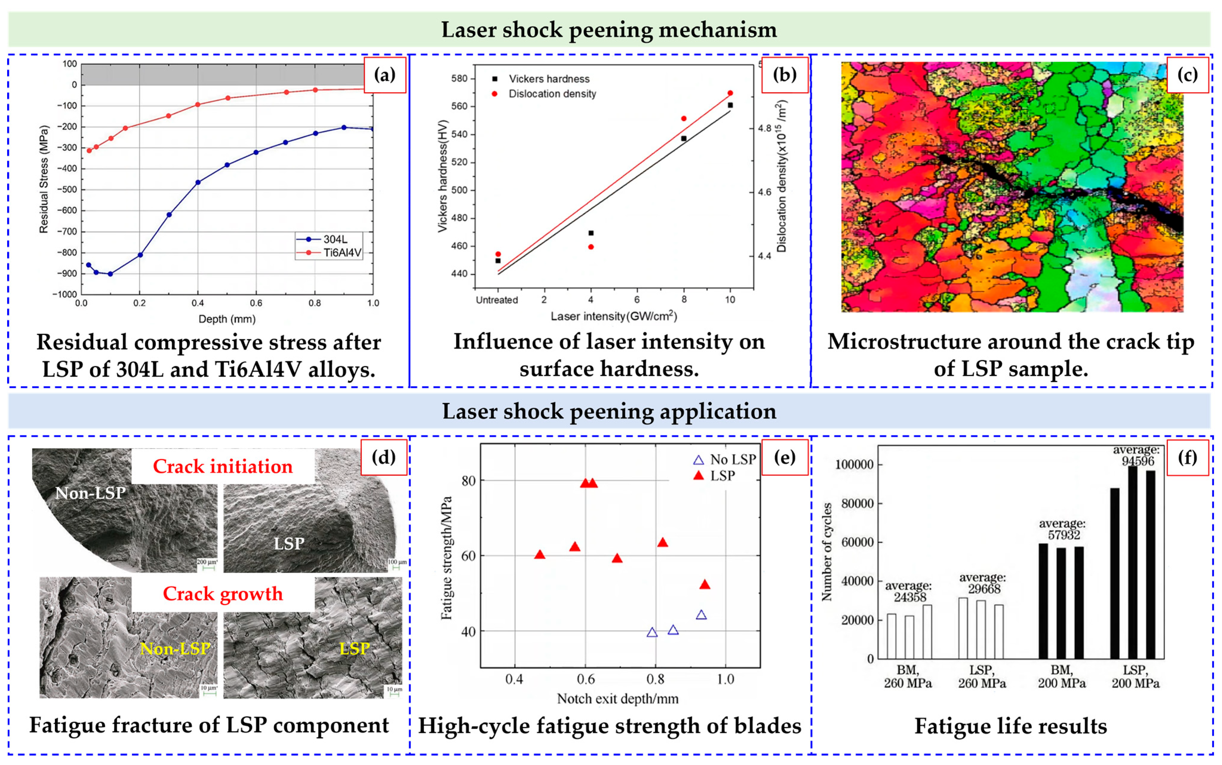
4. Laser Action on Enhancing Metal Fatigue Performance
5. Conclusions
- (1)
- Synergistic processing-property control: The thermo-mechanical coupling effect of nanosecond lasers allows for the simultaneous optimization of microgroove geometry and substrate strengthening. However, the interplay between molten pool behavior, stress field evolution, and defect suppression requires deeper exploration through advanced modeling and in situ characterization.
- (2)
- Multi-dimensional fatigue mechanisms: Residual compressive stress gradients, nanocrystalline surface layers, and geometric discontinuity mitigation collectively enhance fatigue life. Yet, quantitative relationships between laser parameters, stress distribution, and crack initiation/propagation remain underexplored.
- (3)
- Industrial translation challenges: Current studies predominantly focus on laboratory-scale validation. Scaling nanosecond laser processing for large-area aircraft skin applications demands innovations in process efficiency, cost-effective parameter optimization, and fatigue performance standardization.
- (1)
- The development of multi-scale models integrating thermal ablation dynamics, phase transformations, and fatigue crack evolution.
- (2)
- In situ experimental platforms to correlate real-time process monitoring with post-processing microstructure and fatigue behavior.
- (3)
- Intelligent manufacturing frameworks leveraging machine learning to optimize laser parameters for site-specific microgroove geometries and fatigue resistance.
Author Contributions
Funding
Data Availability Statement
Conflicts of Interest
References
- Wang, C.J.; Cheng, L.D.; Xue, S.X.; Chen, P.Y.; Liu, B.S.; Ding, H.; Sun, J.; Xu, Z.H.; Wang, X.W. Manufacturing technologies of bionic micro-structures for drag reduction: A review. J. Netshape Form. Engneering 2019, 11, 88–98. [Google Scholar] [CrossRef]
- Xu, Y.; Zhang, C.; Wang, Z.X. Simulation analysis on drag reduction performance of characteristic parameters of V-groove on local approximate plane. Aeronaut. Manuf. Technol. 2021, 64, 86–99. [Google Scholar] [CrossRef]
- Choi, S.K. Smart flow control with riblets. Adv. Mater. Res. 2013, 745, 27–40. [Google Scholar] [CrossRef]
- Wang, X.L.; Ma, J.W.; Jia, Z.Y.; Gui, C.H.; Qi, X.Q.; Liu, W. Nanosecond laser high-precision fabrication of microgrooves on TC4 surface: Morphology simulation and drag reduction performance of microgrooves. J. Laser Appl. 2022, 34, 042047. [Google Scholar] [CrossRef]
- Gao, X.J.; Wang, H.H.; Zhu, G.M.; Guo, N.N. Research progress in forming process of microgrooves with drag reduction. J. Plast. Eng. 2021, 28, 183–191. [Google Scholar] [CrossRef]
- Yu, K.C.; Shi, H.C.; Zhang, P.L.; Yu, Z.S.; Yan, H.; Lu, Q.H. Micro/nanoengineering of functionalized metal surfaces based on short/ultra-short-pulsed lasers: A review. J. Mater. Sci. 2024, 59, 1819–1866. [Google Scholar] [CrossRef]
- Li, W.J.; Ding, Q.; Sun, F.B.; Liu, B.C.; Yuan, F.S.; Zhang, L.; Bao, R.; Gu, J.H.; Lin, Y.H. Fatigue behavior of zirconia with microgrooved surfaces produced using femtosecond laser. Lasers Med. Sci. 2023, 38, 33. [Google Scholar] [CrossRef]
- Aviation Safety Council. Aviation Occurrence Report Volume I: In-Flight Breakup over the Taiwan Strait Northeast of Makung, Penghu Island China Airlines Flight CI611 Boeing 747-200, B-18255 May 25, 2002; ASC-AOR-05-02-001; Aviation Safety Council: Taipei, China, 2005. [Google Scholar]
- Wang, X.L.; Jia, Z.Y.; Ma, J.W.; Han, D.X.; Gui, C.H.; Qi, X.Q.; Liu, W. Research on nanosecond laser processing of basic unit for ridge surface: Forming condition of microgroove and micro-ridge structure on TC4 surface. Opt. Eng. 2022, 64, 046105. [Google Scholar] [CrossRef]
- Pan, X.L.; Zhou, L.C.; Wang, C.X.; Yu, K.; Zhu, Y.Q.; Yi, M.; Wang, L.F.; Wen, S.F.; He, W.F.; Liang, X.Q. Microstructure and residual stress modulation of 7075 aluminum alloy for improving fatigue performance by laser shock peening. Int. J. Mach. Tools Manuf. 2023, 184, 103979. [Google Scholar] [CrossRef]
- Sun, R.J.; Cao, Z.W.; Ma, X.G.; Che, Z.G.; Zou, S.K.; Wu, J.F. Residual stress and fatigue property of laser shock peening 2050 aluminum-lithium alloy. Laser Optoelectron. Prog. 2023, 60, 204–211. [Google Scholar] [CrossRef]
- Zhang, Q.; Zhu, Y.M.; Gao, X.; Wu, Y.X.; Hutchinson, C. Training high-strength aluminum alloys to withstand fatigue. Nat. Commun. 2020, 11, 5198. [Google Scholar] [CrossRef]
- Li, C.Q.; Tang, S.; Li, Y.; Geng, Z.H. Sub-optimization of riblet shape based on neural networks. J. Aerosp. Power 2022, 37, 639–648. [Google Scholar] [CrossRef]
- Song, J.Z.; Li, G.Y. Shape optimization and mechanism of transverse groove for drag reduction based on genetic algorithm. J. Aerosp. Power 2024, 39, 231–238. [Google Scholar] [CrossRef]
- Wang, X.L.; Jia, Z.Y.; Ma, J.W.; Han, D.X.; Qi, X.Q.; Gui, C.H.; Liu, W. Optimization of nanosecond laser processing for microgroove on TC4 surface by combining response surface method and genetic algorithm. Opt. Eng. 2022, 61, 086103. [Google Scholar] [CrossRef]
- Wang, X.L.; Jia, Z.Y.; Ma, J.W.; Liu, W.; Han, D.X.; Gui, C.H.; Qi, X.Q. Research on simulation of nanosecond pulsed laser processing for TC4 titanium alloy: A novel model simplification and correction method. Opt. Laser Technol. 2022, 147, 107635. [Google Scholar] [CrossRef]
- Nie, Y.H.; Zhang, B.W.; Zhang, P.H.; Huang, Z.K.; A, Z.W. Cracking behavior and gradient power processing strategy in ultrafast laser processing of hard and brittle materials. Chin. J. Lasers 2025, 52, 0802406. [Google Scholar] [CrossRef]
- Wang, Y.F.; Yu, Z.; Li, K.M.; Hu, J. Research on nanosecond laser ablation process of titanium alloy microgroove. J. Donghua Univ. (Nat. Sci.) 2023, 49, 84–94. [Google Scholar] [CrossRef]
- Cao, X.D.; Li, Y.H.; Yang, Y.Q.; Ding, W.W.; Chen, J.; Wu, J.J.; Zhao, J.B.; Qiao, H.C.; Zhao, Y.J. Laser shock processing mechanism and its applications in aeronautical components. Surf. Technol. 2025, 54, 1–15. [Google Scholar] [CrossRef]
- Ye, C.R.; Sun, J.Y.; Long, Y.B.; Zhao, X.J.; Zhang, Z.H.; Yu, Z.R.; Peng, Y.J.; Leng, Y.X. Effect of a non-continuous composite path with zero overlapping rate on cutoff value of detail fatigue rated strength of aerospace titanium alloy TC4 under laser shock peening. Chin. J. Lasers 2024, 51, 2002202. [Google Scholar] [CrossRef]
- Chen, H.W.; Zhang, X.; Ma, L.X.; Che, D.; Zhang, D.Y.; Sudarshan, T.S. Investigation on large-area fabrication of vivid shark skin with superior surface functions. Appl. Surf. Sci. 2014, 316, 124–131. [Google Scholar] [CrossRef]
- Denkena, B.; Kaestner, J.; Wang, B. Advanced microstructures and its production through cutting and grinding. CIRP Ann-Manuf. Technol. 2010, 59, 67–72. [Google Scholar] [CrossRef]
- Song, H.; Liu, Z.Q.; Shi, Z.Y.; Cai, Y.K. Micro-end milling and hydrophobic properties of machined surface for microgroove and microarray. J. Mech. Eng. 2016, 52, 204–211. [Google Scholar] [CrossRef]
- Zhao, Q.L.; Guo, B.; Yang, H.; Wang, Y.L. Technological parameter optimization of micro-structured surfaces by diamond fly-cutting. Opt. Precis. Eng. 2009, 17, 2512–2519. Available online: https://kns.cnki.net/nzkhtml/xmlRead/trialRead.html?dbCode=CJFD&tableName=CJFDTOTAL&fileName=GXJM200910027&fileSourceType=1&appId=KNS_BASIC_PSMC&invoice=uouiVAckJyo9vMIyrLmpWrUPYJ5yMpWFOAe3jxx5gPjxnUt95drcSZIjnc6xPpCRLkrZ7OO1i5hB9HYXO6kkwSoIpHjDKf9g0g2s+RgcjmsYQKUVHKIBxsN4hSe5gnyo6ZL5kaMwR94PkO+KeJO7qamhpqYAyBHRsVjvy3ilcyo= (accessed on 10 May 2025).
- Denkena, B.; Leon, L.D.; Wang, B. Grinding of microstructured functional surfaces: A novel strategy for dressing of microprofiles. Prod. Eng. 2009, 3, 41–48. [Google Scholar] [CrossRef]
- Denkena, B.; Grover, T.; Krawczyk, T. Tools and strategies for grinding of riblets on freeformed compressor blades. Procedia CIRP 2016, 55, 182–187. [Google Scholar] [CrossRef]
- Hockauf, R.; Asadi, E.; Denkana, B.; Grove, T.; Wurz, M. Grinding of riblets with “beaver tooth” multi-layer tools. Procedia CIRP 2018, 71, 155–159. [Google Scholar] [CrossRef]
- Rathod, V.; Doloi, B.; Bhattacharyya, B. Influence of electrochemical micromachining parameters during generation of microgrooves. Int. J. Adv. Manuf. Technol. 2015, 76, 51–60. [Google Scholar] [CrossRef]
- Du, L.Q.; Zhang, X.; Xiao, H.T.; Yu, Y.; Wang, S.Y.; Guan, F.L. Chemical etching of microgroove array on the surface of rotating body. Die Mould Manuf. 2021, 21, 73–78. [Google Scholar]
- Gao, Z.Y.; Peng, L.F.; Yi, P.Y.; Lai, X.M. Grain and geometry size effects on plastic deformation in roll-to-plate micro/meso-imprinting process. J. Mater. Process. Technol. 2015, 219, 28–41. [Google Scholar] [CrossRef]
- Hu, Z.Q.; Wang, B.; Wang, W.; Xun, C. Numerical simulation of microstructure on surface of roll forming sheet. Forg. Stamp. Technol. 2014, 39, 63–67. [Google Scholar] [CrossRef]
- Wang, C.G. Study on Roll Forming Grooves on the Surface of Sheet Metal; Jilin University: Changchun, China, 2016; Available online: https://kns.cnki.net/reader/flowpdf?invoice=ZxxRedI%2F69KCXB%2BE1srVb91D7k1jTIA8RVdiglC%2Fiu3zzxXVXkasRw0Sw5wUbdhI%2FXoaGquKR8xitQtp0ZmbqIGHb75VEZxU6yiqbA%2FQnTmKxrfQDq2i3LZ8E1xsFAnu357r%2BnDl2K2Yc8dQOCZVJ005JnRnpbwfjjRNd%2F5UOWI%3D&platform=NZKPT&product=CMFD&filename=1016084438.nh&tablename=cmfd201602&type=DISSERTATION&scope=trial&dflag=pdf&pages=&language=CHS&trial=&nonce=7CCCBD64CA464EAD8997FBD8DF1FC23B&cflag=pdf (accessed on 10 May 2025).
- Lu, B.; Meng, W.J. Roll molding of microchannel arrays on Al and Cu sheet metals: A method for high-throughput manufacturing. J. Micro Nano-Manuf. 2014, 2, 7–11. [Google Scholar] [CrossRef]
- Zhou, R.; Cao, J.; Ehmann, K.; Xu, C. An investigation on deformation-based micro surface texturing. J. Manuf. Sci. Eng.-Trans. ASME 2011, 133, 061017. [Google Scholar] [CrossRef]
- Romans, T.; Hirt, G. Rolling of drag reducing riblet-surfaces. In Proceedings of the AIAA/ASME/ASCE/AHS/ASC Structures, Structural Dynamics, and Materials Conference, Orlando, FL, USA, 12–15 April 2010. [Google Scholar] [CrossRef]
- Shimoyama, K.; Yokoyama, S.; Kaneko, S.; Fujita, F. Effect of grooved roll profiles on microstructure evolutions of AZ31 sheets in periodical straining rolling process. Mater. Sci. Eng. A-Struct. Mater. Prop. Microstruct. Process. 2014, 611, 58–68. [Google Scholar] [CrossRef]
- Klocke, F.; Feldhaus, B.; Wegner, H.; Baecker, V. Rolling of defined riblet structures on compressor blades of Ti6Al4V. Steel Res. Int. 2010, 81, 178–181. Available online: https://webofscience.clarivate.cn/wos/alldb/full-record/WOS:000208594600042 (accessed on 10 May 2025).
- Tekkaya, A.E.; Homberg, W.; Brosius, A. 60 Excellent Inventions in Metal Forming; Springer: Berlin/Heidelberg, Germany, 2015; Available online: https://link.springer.com/book/10.1007/978-3-662-46312-3 (accessed on 10 May 2025).
- Hergt, A.; Hage, W.; Grund, S.; Steinert, W.; Terhorst, M.; Schongen, F.; Wilke, Y. Riblet application in compressors: Towards efficient blade design. J. Turbomach.-Trans. ASME 2015, 137, 111006. [Google Scholar] [CrossRef]
- Kaakkunen, J.J.J.; Tiainen, J.; Jaatinen-Varri, A.; Gronman, A.; Lohtander, M. Fabrication of surfaces with reduced friction using nanosecond laser. Procedia Manuf. 2018, 17, 14–21. [Google Scholar] [CrossRef]
- Kaakkunen, J.J.J.; Tiainen, J.; Jaatinen-Varri, A.; Gronman, A.; Lohtander, M. Nanosecond laser ablation of the trapezoidal structures for turbomachinery applications. Procedia Manuf. 2018, 25, 435–442. [Google Scholar] [CrossRef]
- SIiegel, F.; Klug, U.; Kling, R. Extensive micro-structuring of metals using picosecond pulses-ablation behavior and industrial relevance. J. Laser Micro Nanoeng. 2009, 4, 104–110. [Google Scholar] [CrossRef]
- Zemaitis, A.; Miksys, J.; Gaidys, M.; Gecys, P.; Gedvilas, M. High-efficiency laser fabrication of drag reducing riblet surfaces on pre-heated Teflon. Mater. Res. Express 2019, 6, 065309. [Google Scholar] [CrossRef]
- Takayama, N.; Asaka, S.; Yan, J.W. Nanosecond pulsed laser irradiation of sapphire for developing microstructures with deep V-shaped grooves. Precis. Eng.-J. Int. Soc. Precis. Eng. Nanotechnol. 2018, 52, 440–450. [Google Scholar] [CrossRef]
- Sahu, A.K.; Jha, S. Microchannel fabrication and metallurgical characterization on titanium by nanosecond fiber laser micromilling. Mater. Manuf. Process. 2020, 35, 279–290. [Google Scholar] [CrossRef]
- Okamoto, Y.; Okubo, T.; Kajitani, A.; Okada, A. High-quality micro-shape fabrication of monocrystalline diamond by nanosecond pulsed laser and acid cleaning. Int. J. Extrem. Manuf. 2022, 4, 025301. [Google Scholar] [CrossRef]
- Stein, P.; Garcia, O.; Morales, M.; Huber, H.P.; Molpeceres, C. Numerical simulation of laser ablation for photovoltaic materials. Appl. Surf. Sci. 2012, 258, 9288–9291. [Google Scholar] [CrossRef]
- Vasantgadkar, N.A.; Bhandarkar, U.V.; Joshi, S.S. A finite element model to predict the ablation depth in pulsed laser ablation. Thin Solid Film. 2010, 519, 1421–1430. [Google Scholar] [CrossRef]
- Zhang, J.J.; Zhao, L.; Rosenkranz, A.; Song, C.W.; Yan, Y.D.; Sun, T. Nanosecond pulsed laser ablation on stainless steel combining finite element modeling and experimental work. Adv. Eng. Mater. 2019, 21, 1900193. [Google Scholar] [CrossRef]
- Zhang, J.J.; Zhao, L.; Rosenkranz, A.; Song, C.W.; Yan, Y.D.; Sun, T. Nanosecond pulsed laser ablation of silicon—Finite element simulation and experimental validation. J. Micromech. Microeng. 2019, 29, 075009. [Google Scholar] [CrossRef]
- Zhao, W.; Yu, Z.; Hu, J. Numerical simulation and experimental analysis on nanosecond laser ablation of titanium alloy. J. Manuf. Process. 2023, 99, 138–151. [Google Scholar] [CrossRef]
- Takayama, N.; Yan, J.W. Mechanisms of microgroove formation on single-crystal diamond by a nanosecond pulsed laser. J. Mater. Process. Technol. 2017, 243, 299–311. [Google Scholar] [CrossRef]
- Charee, W.; Qi, H.; Zhu, H.; Saetang, V. Coaxial water and air jet-assisted laser micromachining of titanium. Int. J. Adv. Manuf. Technol. 2022, 121, 5605–5616. [Google Scholar] [CrossRef]
- Zhang, H.Z.; Huang, T.; Liu, Z.; Zhang, X.; Lu, J.L.; Xiao, R.S. High fluence nanosecond laser machining of SiCp/AA2024 composite with high pressure assistant gas. J. Manuf. Process. 2018, 31, 560–567. [Google Scholar] [CrossRef]
- Zhang, Z.; Zhang, Q.L.; Wang, Q.W.; Su, H.H.; Fu, Y.C.; Xu, J.H. Investigation on the material removal behavior of single crystal diamond by infrared nanosecond pulsed laser ablation. Opt. Laser Technol. 2020, 126, 106086. [Google Scholar] [CrossRef]
- Xing, Y.Q.; Liu, L.; Wu, Z.; Wang, X.S.; Huang, P.; Tang, L. Fabrication and characterization of micro-channels on Al2O3/TiC ceramic produced by nanosecond laser. Ceram. Int. 2018, 44, 23035–23044. [Google Scholar] [CrossRef]
- Xing, Y.Q.; Liu, L.; Hao, X.Q.; Wu, Z.; Huang, P.; Wang, X.S. Micro-channels machining on polycrystalline diamond by nanosecond laser. Opt. Laser Technol. 2018, 108, 333–345. [Google Scholar] [CrossRef]
- Wang, Y.T.; Zhao, X.Y.; Ke, C.J.; Yu, J.; Wang, R. Nanosecond laser fabrication of superhydrophobic Ti6Al4V surfaces assisted with different liquids. Colloid Interface Sci. Commun. 2020, 35, 100256. [Google Scholar] [CrossRef]
- Dwivedi, P.K.; Sivateja, C.; Rai, A.K.; Ganesh, P.; Basu, A.; Dutta, K. A comparative assessment of the effects of laser shock peening and ultrasonic shot peening on surface integrity and ratcheting fatigue performance of HSLA steel. Int. J. Fatigue 2023, 176, 107902. [Google Scholar] [CrossRef]
- Bae, S.; Kim, Y.; Jung, J.; Shin, K.; Suh, C.; Jeong, S. Effects of laser shock peening on Inconel 738LC to improve mechanical and fatigue characteristics. Opt. Laser Technol. 2024, 171, 110290. [Google Scholar] [CrossRef]
- Khanigi, A.F.; Shahverdi, H.; Farnia, A. Experimental and numerical investigation of residual stresses in laser shock peened Rene-80 Ni-based superalloy. Appl. Phys. A-Mater. Sci. Process. 2024, 130, 599. [Google Scholar] [CrossRef]
- Digonta, H.M.D.A.; Fatemi, A. Laser shock peening and its effects and modeling on fatigue performance of additive manufactured metallic materials. Theor. Appl. Fract. Mech. 2024, 130, 104281. [Google Scholar] [CrossRef]
- Bai, Y.T.; Ma, Y.; Zhou, X.H.; Wang, H.; Liu, J.P. A simulation study on fatigue life enhancement of composite steel-concrete beams after laser shock peening. Eng. Mech. 2025, 1–12, (Online first-published paper). [Google Scholar] [CrossRef]
- Sun, Y.F.; Liu, W.J.; Zhang, H.W.; Su, Y.; Wei, Y.H.; Liu, G.S.; Yu, X.F. Simulation of residual stress evolution of 8Cr4Mo4V steel induced by laser shock and its influence on fatigue performance. Chin. J. Mater. Res. 2023, 37, 933–942. Available online: https://kns.cnki.net/nzkhtml/xmlRead/trialRead.html?dbCode=CJFD&tableName=CJFDTOTAL&fileName=CYJB202312007&fileSourceType=1&appId=KNS_BASIC_PSMC&invoice=Ol8HasGCvRbQgE0oF0HCR8j1xsP0IAq2buLvU68POVkMTJcSTQ3R6Bxkvgjg3ytw81HR5McYcbEs4nwvZI4QGT7DahlIbLiWZHcWwpA20el3lwYzsQcldcSM9HRPVaUFU0yZp+1zrhcCFiq8bUiQX8cvhgQGKeEtsjTlOeZ1lGY= (accessed on 10 May 2025).
- Rodríguez, V.M.; Gonzalez, C.R.; Garcia, S.F.; Garciduenas, H.C.; Morelos, V.H.L.; Ruiz, A. Analysis of the effects of isothermal aging and laser shock peening on the flow properties, fatigue crack growth, and fracture toughness of Inconel 718. Opt. Laser Technol. 2023, 162, 109288. [Google Scholar] [CrossRef]
- Maleki, E.; Unal, O.; Doubrava, M.; Pantelejev, L.; Bagherifard, S.; Guagliano, M. Application of impact-based and laser-based surface severe plastic deformation methods on additively manufactured 316L: Microstructure, tensile and fatigue behaviors. Mater. Sci. Eng. A-Struct. Mater. Prop. Microstruct. Process. 2024, 916, 147360. [Google Scholar] [CrossRef]
- Flores-García, S.; Martínez-Pérez, C.E.; Rubio-González, C.; Banderas-Hernandez, J.A.; Felix-Martinez, C.; Jimenez, S.M.A. Fatigue life and residual stress of flat stainless steel specimens laser-cladded with a cobalt-based alloy and postprocessed with laser shock peening. J. Manuf. Mater. Process. 2024, 8, 45. [Google Scholar] [CrossRef]
- Liu, Y.P.; Shi, Z.J.; Zhao, Y.Z.; Zhu, L.; Liu, M.B. Cut-off value of detail fatigue strength of TC4 Titanium alloy with compound strengthening treatment by laser shock peening and shot peening. Chin. J. Lasers 2020, 47, 371–378. [Google Scholar] [CrossRef]
- Lu, W.X.; Hu, D.Y.; Yan, L.; Mao, J.X.; Guo, X.J.; Shan, X.M.; Zhang, Y.K.; Wang, R.Q. Effects of laser shock peening on fatigue strength of blade leading edge with foreign object damage. J. Propuls. Technol. 2024, 45, 2301003. [Google Scholar] [CrossRef]
- Jin, D.; Liu, Z.; Guo, C.Y.; Li, Z.Q.; Sun, M.Y. Effect of laser shock peening on fatigue life for FV520B steel. China Surf. Eng. 2024, 37, 280–286. [Google Scholar] [CrossRef]
| Systems | Parameters | Conditions | References |
|---|---|---|---|
| Nanosecond laser system | Pulse duration: 10–100 ns | Material: aluminum alloy, titanium alloy et al. | [9,15] |
| Auxiliary gas system | Pressure: Variable | - | [45] |
| Scanning system | Scanning speed: Variable | Environment: air, liquid | [53,58] |
Disclaimer/Publisher’s Note: The statements, opinions and data contained in all publications are solely those of the individual author(s) and contributor(s) and not of MDPI and/or the editor(s). MDPI and/or the editor(s) disclaim responsibility for any injury to people or property resulting from any ideas, methods, instructions or products referred to in the content. |
© 2025 by the authors. Licensee MDPI, Basel, Switzerland. This article is an open access article distributed under the terms and conditions of the Creative Commons Attribution (CC BY) license (https://creativecommons.org/licenses/by/4.0/).
Share and Cite
Wang, X.; Jia, Z.; Ma, J.; Liu, W. Nanosecond Laser Etching of Surface Drag-Reducing Microgrooves: Advances, Challenges, and Future Directions. Aerospace 2025, 12, 460. https://doi.org/10.3390/aerospace12060460
Wang X, Jia Z, Ma J, Liu W. Nanosecond Laser Etching of Surface Drag-Reducing Microgrooves: Advances, Challenges, and Future Directions. Aerospace. 2025; 12(6):460. https://doi.org/10.3390/aerospace12060460
Chicago/Turabian StyleWang, Xulin, Zhenyuan Jia, Jianwei Ma, and Wei Liu. 2025. "Nanosecond Laser Etching of Surface Drag-Reducing Microgrooves: Advances, Challenges, and Future Directions" Aerospace 12, no. 6: 460. https://doi.org/10.3390/aerospace12060460
APA StyleWang, X., Jia, Z., Ma, J., & Liu, W. (2025). Nanosecond Laser Etching of Surface Drag-Reducing Microgrooves: Advances, Challenges, and Future Directions. Aerospace, 12(6), 460. https://doi.org/10.3390/aerospace12060460