Article

Destructive and Non-Destructive Analysis of Lightning-Induced Damage in Protected and Painted Composite Aircraft Laminates

by
Audrey Bigand
1,2,
Christine Espinosa
1,* and
Jean-Marc Bauchire
3
1
Institut Clément Ader (ICA), Université de Toulouse, CNRS, ISAE-SUPAERO, UPS, INSA, IMT Mines Albi, 3 Rue Caroline Aigle, 31400 Toulouse, France
2
Airbus Operations SAS, 316 Route de Bayonne, 31060 Toulouse Cedex 9, France
3
GREMI, UMR 7344, CNRS-University of Orleans, 14 Rue d’Issoudun, BP 6744, 45067 Orleans Cedex 2, France
*
Author to whom correspondence should be addressed.
Aerospace 2025, 12(5), 446; https://doi.org/10.3390/aerospace12050446
Submission received: 27 February 2025 / Revised: 5 May 2025 / Accepted: 13 May 2025 / Published: 19 May 2025
(This article belongs to the Section Astronautics & Space Science)

Abstract

:
The use of CFRP composite increased significantly since the last 40 years for aircraft structure. Unfortunately, such structures are subjected to significant damages if struck by lightning compared to metallic structure. This is mainly due to the low conductivity of this material, which cannot evacuate the current without high Joule heating. Lightning strike-induced damage in a composite laminate is composed of in-depth delamination, fibre breakage, and resin deterioration due to the surface explosion and the core current flow linked to interaction of the arc with the surface. But very rare previous studies dedicated to the analysis of damage as a direct effect of lightning have considered the spurious effect of the paint that always covers real aeronautic structures neither on the thermal nor the mechanical loads that are the root cause of these damages. We present in this paper a coupled non-destructive and destructive damage analysis to support the proposition of damage scenarios depending on the presence and thickness of the paint. The mechanical and thermal sources contribution in the global loading on the core damage is discussed, which confirms previous studies’ analysis and modelling and is in accordance with existing works in the literature.

1. Introduction and State-of-the-Art

Aircraft design is increasingly based on Carbon Fibre-Reinforced Plastic composite structures (CFRP). Unfortunately, the low conductivity of this material compared to metal makes it very weak against lightning strike [1,2]. The conductivity of the fibres is around 1000 times less than that of metal and the transverse conductivity (both in the plane and in the thickness of the laminate) is even poorer because of the resin matrix, which is a dielectric [3,4]. Compared to metals, composite laminates suffer from more severe damage when submitted to a lightning strike [5,6,7]. To reduce the damage in depth, two strategies can be adopted: either improving the efficiency of the protection or improving the damage resistance of the composite laminates. Without changing the lightning strike protection (LSP) layers, some authors have used short carbon fibres in the thickness direction for example [8]. To optimize the design of new aircraft structures, it is also useful to go through numerical modelling and compare results with tests [9,10,11]. For all these purposes, it is mandatory to understand at first the main physical phenomena, characterize the behaviour of materials, and obtain representative and robust data [10,12].
In this paper, it is intended to give insight into the effect of the LSP layers destruction on the damage distribution into the underlying composite laminate. The focus is set on the opposite effect of paint on the LSP performance to prevent current flowing into the laminate depth generating thermal damage and delamination.
The paper presents first some protection strategies and their effect on the direct damage that can be observed. A pragmatic and simple manner is adopted to differentiate loads and sources of damage.
Then, the experimental study and the analysis of the damages produced by laboratory lighting tests are presented. CFRP laminates typical of an aircraft structure configuration with different paint and metallic protection statements are compared to differentiate the contribution of mechanical impact load from the thermal-induced shock.
Non-Destructive Test (NDT) measurements of delamination are completed with destructive measurements performed on several plates to enhance the identification of localization and extent at each interface. It is shown that the destructive analysis of delamination gives a better insight into the delamination distribution in the thickness compared to NDT top view images. Based on this more precise damage identification, the main contribution of each load is discussed, with the objective to isolate the effect of the paint and consolidate the proposed damage generation scenario.

1.1. Lightning Direct Damage on Composite Laminates

Lightning strikes are defined as current delivery waveforms for certification requirements in laboratory tests [13]. The waveform under concern here is the so-called D. The current is a high amplitude idealized current delivery signal that reaches I = 100 kA ± 10% in about 20 µs and decreases in about 100µs reaching half of its highest intensity in 50 µs. The action integral (AI), which is defined as the integral over the time delivery of current, of the square of the current intensity, is also a criterion that defines the aggression of the lightning strike. For a D waveform under concern, this AI is prescribed to reach 250 kA2 · s ± 20%, as given by the integration over time of the square of the current I.
To better understand the damage mechanism in the composite, called direct damage, many studies have been performed, among them reviews [1,10,14,15,16,17]. It is intended here to analyze when, where, and how they are produced.
Extreme temperatures are experienced due to the lightning arc interface and the high current concentration leading to Joule heating [14,15]. Fibre breakage occurs due to the lightning arc interaction and entry of current that heat the fibres, probably up to sublimation [18]. Tufts of broken fibres are usually limited to the first CFRP plies but can go deeper if the arc is constrained. In addition, due to the very high temperature (up to 30,000 K) of the environment due to Joule heating of the fibres and the arc interaction, resin deterioration [14,15] occurs since the temperature for the pyrolysis of the epoxy resin of about 300–600 K is far overpassed [10]. These two damages are thermal damage due to thermal loading [19]. They could also lead to additional explosions with gas release, that is, they could generate a mechanical loading coming from this thermal source. Finally, in the core of the structure, post-mortem delamination and ply damage have been observed. This damage is related to the shockwave and explosion at the surface that leads to a high overpressure [20]. These surface/thermal and core/mechanical processes are not independent, and their interactions can lead to major damage, up to puncture.
The most visible residual damage is of course the damage occurring at the surface of the structure. But the most extensive and detrimental damage is the hidden one: the core damage [14]. Surface damage is usually limited to the vicinity of the arc injection, covering quite a small area of tens of square millimetres when observed from the top view. Core damage, indeed, delamination essentially, can be much widely extended than the visual damage and reach tens of thousands square millimetres [21]. This defect will significantly degrade the residual mechanical properties and strength of the structure, which may no longer be able to sustain flight loads. This could impact flight safety. Such damage can unfortunately only be measured by specific means, usually Non-Destructive Test devices (NDT) such as ultra-sonic scanning, which gives the projected delamination area of the panel view from the top face, which is the face hit by the arc. On the one hand, NDT gives a partial measure of core damage. On the other hand, most of existing studies concerning lightning damage considered bare and unprotected laminates. However, this situation is not representative of an aircraft design.

1.2. Damage Limitation with Lightning Strike Protection Technologies

A lot of researchers have worked on the performance of different protections, among them conductive paints or carbon nanotubes. Recent reviews give key references about these works [4,7,22,23].
To limit the damage, aircraft manufacturers use a Lightning Strike Protection (LSP) applied on the external surface of the composite. This is a conductive sacrificial layer that is used to divert the lightning current from the CFRP. The layer is made of a conductive material to act as the primary current path due to its low electrical resistivity compared to CFRP. It is called a sacrificial layer as it will be vaporized by the lightning current but since it is not part of the structure, this has no impact on safe flight and landing. The most common technologies are expanded metallic foil such as Expanded Copper Foil (ECF) and metallic mesh such as Bronze Mesh (BM) [24]. The difference between the mesh and the expanded foil is that the mesh is made of different wires that are meshed in a defined pattern and the expanded foil is made from a unique foil that has been punctured and then expanded and rolled to create its final flat shape and desired thickness. There is, thus, a contact penalty for the mesh, making it less efficient compared to expanded foil of an equivalent weight [25]. Obviously, a continuous metallic foil is the best mean of protection for lightning current dissipation as it facilitates the current flow and provides a complete “shielding effect” for the composite skin (see Figure 1). There are, however, two main drawbacks with the implementation of this technology on aircrafts: the drapability and the adhesion that leads to peeling problems with the paint, and the lightning strike protection itself. To solve these manufacturing and operability issues, different technologies have been developed as presented in [23]. Unfortunately, these technologies do not solve the adhesion issue and could be quite complex to implement in the production cycle (vacuum chamber sized for an airplane complete structure). Finally, the easiest and cheapest way to ensure adhesion of the metallic protection to the composite is to create areas of attachment where there is no metal and the resin can flow through.
Another way to ensure the protection without adding a metallic layer is to introduce conductive fibres in the laminate itself either with metallic wires or by embedding composite fibres of the first ply in a conductive coating. With this process, the conductivity of the first composite ply is increased with the aim of sustaining a lightning strike. Unfortunately, this protection is not as efficient as ECF since it does not prevent the injection of current into the CFRP thickness. On the same principle of developing a self-protection of the structure, transverse conductivity of the composite has been achieved by the addition of conductive particles in the matrix. Usually, the technology considered is based on carbon nanotubes (CNT), graphene, or metal particles [2,26,27]. The objective is to reduce the Joule heating created by the flow of current through the composite, by increasing the electrical conductivity of the material, or by reducing the electrical density, i.e., by distributing the current more evenly through the composite. By this mechanism, thermal damage is reduced. But, again, the efficiency of the protection has not been demonstrated, and it usually impinges on the mechanical properties of the laminates, which is detrimental for the design [2]. Moreover, the manufacturing processes are usually quite expensive. Finally, the use of conductive paints has been considered by the addition of conductive particles in the polymer but the contact between the particles is not dense enough to be of use for lightning protection [22]. Since the LSP on the surface is more conductive than the underlying structure, the current will mainly flow in this external layer and most of the energy will be dissipated in this layer as well. In this respect, any lightning strike protection will be efficient to reduce the damage compared to a bare composite [28].

1.3. Paint Effect

In the different developments of lightning protection technologies, one important parameter is seldom considered: the paint. Obviously, aircraft are painted to protect the structure from the environment (UV, fluids, etc.) and to respond to the airline’s desire for customisation. The paint is considered as a merely cosmetic and insulating feature with no structural properties. However, lightning damage is highly dependent on the interaction between the arc and the structure. Within Airbus, investigations have highlighted that the damage remains limited around the arc hit and in the first ply for bare CFRP laminates but is increased with the paint thickness up to puncture in some extreme cases (see Figure 2). As the arc cannot spread freely, it is concentrated in a local area and the current is more and more deeply injected because of the paint [24].
A free arc root will expand quickly in the air as a function of the conductivity of the surface: the lower the conductivity compared to the arc, the quicker the expansion is [29]. Consequently, the efficiency of a lightning strike protection layer decreases dramatically if covered by paint, in a progressive but not linear manner with the paint thickness [30]. It has been shown that there is a yield in the paint thickness over which damage increase dramatically even in presence of a LSP layer on the composite laminate.
Few studies have been reported on the influence of the paint in lightning damage [26]. Some authors, and internal Airbus work showed during lightning laboratory tests that the paint was partially ejected during the test [10]. This ejection occurs in the early instants of the current injection. This phenomenon is assumed to be due to the Joule heating of the metallic protection, leading to its explosion, as described previously. The confinement by the paint of the overpressure due to gas expansion enhances the stress and increases the damage [31]. Lepetit [32] and Karch [18] were the first to consider the confinement effect of the paint. They considered it as a simple mass having an inertial effect on the overpressure of the gas pushing at the composite surface. Based on this approach, the mass density and the thickness of the paint are the only parameters that affect the overpressure enhancement, which reduce the effect of the paint to a sole mechanical over pressure. A lighter or thinner paint will lead to a lower pressure and, thus, should decrease the damage [18].
This 1D theory was the first trial to provide a quantitative explanation of the paint influence. It needs to be enhanced however, since it considers the pressure in a central point only and simplifies the confinement to a mass effect. Other similar approaches have been used to simulate the effect of paint on resultant pressure [31].
We suggest that another more complex phenomenon arises and superposes to the inertial effect and gas containment. The paint that is still present on the laminate during the current injection will also have an electrothermal effect, because it constrains the arc root expansion, thus counteracting the beneficial effects of the LSP. With the vaporization of the LSP and the resin of the top plies of the laminate, if prevented from freely spreading laterally, the concentrated arc will be forced to flow into the underlying composite. The paint would then have an action on the arc root behaviour and, therefore, also on the current distribution into the LSP or deeper in the laminate. This could, thus, modify the space time profile of the explosion that ensues, and the over pressure applied on the composite laminate consequently. The paper presents work performed to sustain this hypothesis.

2. Damage Source Decomposition on Real Aircraft Structure: The Proposed Hypothesis

Considering the entire system (CFRP laminate, LSP and paint), and similarly to unprotected laminates, the damage can be at first broken down into two major elements surface and core.
The surface damage can be measured by a visual inspection from the top view (see Figure 3). Cosmetic damage consists of the vaporization of the LSP and the paint that is ejected (in the red circle). The damage that affects the structure integrity is composed of free of resin that is vaporized and broken dry fibres (tufting) as explained earlier. This region is circled in green. This surface damage [32] is mainly due to the electro-thermal source, which is the Joule effect of the lighting current in the LSP and in the composite laminate, already described in this paper.
The structural so called ‘core damage’ requires a specific inspection to be quantified, such as the delamination area from top or non-impact side view measured through ultra-sonic scan [20,32]. There may also be thermal damage concentrated in the centre of the impact due to the increase in the current injection in the depth of the laminate with the concentrated arc, which can also create fibres tufting. But the main issue is delamination [33,34]. It can be seen in Figure 4 that delaminated interfaces present no trace of burned or heated zone or thermal damage. Delamination has, thus, entirely a mechanical origin and is then considered as mechanical damage.
Some authors have reproduced by numerical simulation the global movements of the lighted laminates as well as the total delaminated area using only a mechanical impact load [35,36]. But it was demonstrated that the delamination distribution in the thickness was not properly reproduced using a pure mechanical load [20]. It is set that the source load of the internal ‘core damage and delamination’ is the combination of a pure mechanical load due to the surface explosion (like a shock pressure) applied onto the surface of the bare composite laminate alone, and a thermal load with induced mechanical load due to core current flow. The principle is described in Figure 5.
The two major elements, surface and core, are indeed not completely separated. A lightning strike is a far more complex phenomenon than thermal damage due to current flow in the structure while it is partially composed of it. Electrothermal and mechanical damage are produced simultaneously and interact [37,38]. Due to the explosion effect, the main different loads that create the core damage have both thermal and mechanical sources [18]. The external load arising from lightning strike protection explosion confined by the paint is considered as a mechanical load applied on the first layer of the laminate. The explosion itself has its origin from a thermal source. This load is considered as the main source of delamination. Indeed, this event arises in the very first instants of the current delivery, even before the maximum current amplitude is reached [39].
The lightning current flowing into the composite generates Joule heating considered as a thermal load responsible of resin deterioration (thus, of dry fibres) and broken fibres at the arc root attachment. This is called the internal damage. This rapid resin vaporization and fibre deterioration can also be seen as an explosion and, therefore, considered as a source of another mechanical load. This mechanical load is emphasized as being slower and of negligible contribution compared to the one generated by the surface explosion. This will be demonstrated later in Section 4. Even though delamination is also a damage to the laminate, it is considered as a damage localized at plies interfaces, whereas what is called internal damage is a distributed damage in the thermally affected zone.
The core damage generation scenario analysis that will be presented and discussed later in this paper assumes that the delamination (mechanical load-induced damage) and the internal damage (thermal load-induced damage) can be considered mainly independently. Indeed, the two loads typical durations are not of the same order. The question that is asked is if paint can change the proportion of the two loads and, thus, the proportion of each damage, even change the scenario of damage generation and source dependency.

3. Materials and Methods

To study the different parameters that play a role in the generation of lightning damage, specific lightning tests were performed during the EDIFISS project designed and realized at Airbus. Among the numerous test configurations, some are used here to analyze the effect of paint on the scenario of damage generation.
The methodology that has been chosen in this work is to organize our analysis around two major axes of investigation: decomposition of damage sources, and core damage source dependency. We have investigated the peculiar influence of the paint.

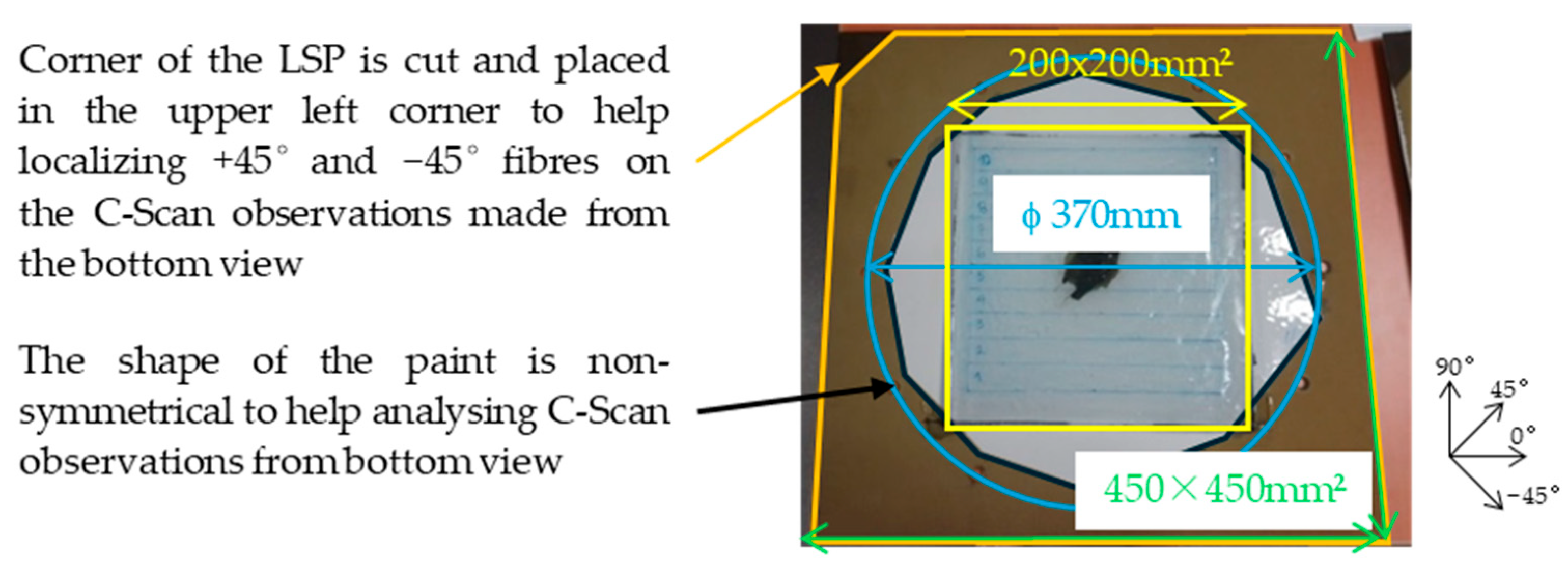
3.1. Specimen Preparation

Specimens are flat square 450 mm × 450 mm composite laminates composed of 13 carbon fibre reinforced resin plies of 127 µm thickness. The layup is symmetrical [45/−45/90/45/−45/0/90/0/−45/45/90/−45/45] and the total thickness is 1.651 mm. Each ply is made of IMA/M21E from Hexcel Corporation (Stamford, CT, USA) and fabricated by AIRBUS (Toulouse, France). The top face is the face covered by LSP layer composed by ECF from and polyurethan paint and hit by the lightning strike. The bottom face is the bare opposite one from which rear face displacements are measured. For damage analysis, plies are numbered from 1 to 13 from the top face to the bottom; while interfaces are numbered the opposite way, from the bottom face to the top. This is because of the position of the laminate in the C-Scan water tank during the NDT observations.
The confinement effect at the surface is studied through the influence of paint thickness on the core damage severity. The waveform under concern in these cases is the D waveform of 100 kA [13]. Different paint thicknesses were considered in the test campaign from 50 µm to 1000 µm. For sake of simplicity and concision in this paper, results of tests with 250 µm, 400 µm, and 1000 µm have been selected for the analysis because the influence is sensitive only above a minimum value [24]. The LSP was in all cases ECF195 from Dexmet® Cie (now PPG Industries Ohio (USA)), except one configuration without LSP chosen to study the thermal damage in the composite. To evaluate the influence of the amount of core current that is let to dive, that is stopped or that is amplified depending on the paint thickness on delamination generation (mechanical damage generated by the mechanical load produced by the thermal source), other tests have been realized on glass fibre composite laminates covered by LSP and paint, and others on CFRP panels identical to previously described but with no LSP and 400 µm paint at increasing current peaks. Currents from 5 kA to 13 kA, and to 25 kA have been chosen to be compared with the reference baseline case (sample 1). A summary of the user cases is listed in Table 1 below.

3.2. Experimental Study

Tests were realized by DGA-Ta using the lightning generator EMMA designed by Airbus and DGA to produce lightning current waveforms as per ED-84 described in Section 2. This generator is a unique prototype manufactured in 2014 by the “Groupe d’étude et de recherche appliquée à la compatibilité” (GERAC), which has become an entity of SOPOMEA Velizy-Villacoublay France in 2019. The set-up is illustrated in Figure 6.
During the experiments, an electric current is delivered at the centre of the panel on the top face covered by the LSP and the paint. The lightning current is injected by an arc from an electrode placed 50 mm away from the panel, initiated by a metallic wire (≤100 µm) into the panel grounded to a metallic frame (Figure 6). All the samples are mechanically and electrically perfectly bonded to a circular metallic frame through 12 fasteners distributed along its 370 mm diameter. The rear face displacement is measured thanks to the Digital Image Correlation (DIC) technique used by DGA-Ta [20].

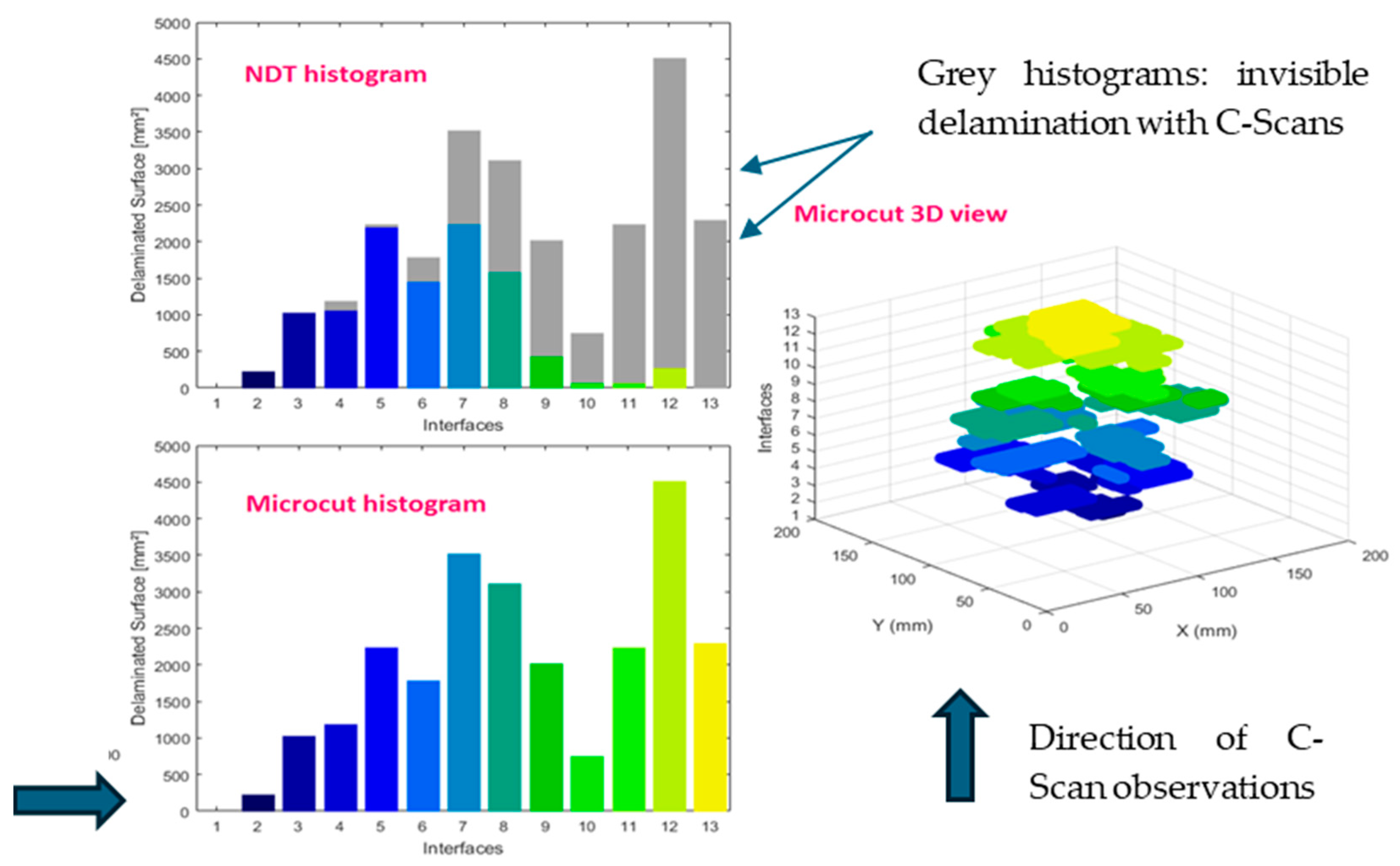
3.3. Damage Measurement Methods

A C-Scan Non-Destructive Test (NDT) was performed for each configuration of sample before cutting to measure the delamination pattern. The C-Scan NDT method measures the echo of the delamination from the back of the panel, i.e., from the opposite face to the sensor position. Since the sensor was placed in front of the bottom face to limit the disturbance of the ECF on the echo, then the delamination areas close to the top face (close to arc attachment) are hidden by the deepest one that are closer to the bottom face and then are less or even not at all detected. A 128 elements MULTI 2000 probe from M2M Cie les Ulis France is used for emission and reception of the signals. Typical frequency of the probe is 10 MHz. Data were analyzed using the software Ultis developed by AIRBUS Group Innovation (Suresnes France) with version ULTIS V03 of TESTIA Cie from Toulouse France. The longitudinal sound speed in the composite depth was approximated to 3100 mm/ms, and the thickness of each ply is set to 0.123 mm. This value of velocity comes from analytical computation of time travelling of the wave knowing the total thickness of the bare composite laminate (without LSP and without paint). The Time Corrected Gain (TCG) was set to 100% to easily locate the bottom echo signal and set the signal door properly. The probe displacement velocity was 20 mm/min, and the pitch resolution was 0.5 × 0.5 mm2.
To complete the classical projected global delamination area that an ultrasonic scan can provide from bottom view, micro-cuts were performed to determine the complete distribution of delamination in the depth.
Damaged composite plates after the lightning strike were partially covered by a volume of polyester resin plot on their top surface to freeze the damage and prevent spurious damage creation or propagation during the cutting process. The liquid polyester resin is deposited on the top of the plate and can flow inside the plate to freeze the deformed shape of the fibres and paint on top. Depending on the tufted fibres due to the thermal damage, the plot can quite be thick from 15 to 30 mm above the nominal paint external face. The composite plate flexural rigidity is increased by the presence of the solid covering resin plot, which decreases as a matter of fact its vibrational natural frequencies due its mass and damping natural properties. To reduce as much as possible vibrations induced by the cutting process that could be responsible of spurious delamination extension during cutting, the plate and all its cut bands are clamped. The lateral dimensions of the resin plot are also different for all samples to be sure to cover all delamination that have been detected by the C-Scan from bottom view and the ones that are expected to be measured after cutting while reducing as much as possible spurious delamination extent during cutting. To be sure of the measurement of delamination is performed in the 0° direction orientation for all samples by C-Scans and by cuttings, either the paint shape or the LSP shape present some non-symmetrical visual geometric cues. The fixing holes are also reference points to help position the beginning of the resin block cutting strip in relation to the full dimensions of each sample. Figure 7 presents one panel example with the resin plot contour highlighted in yellow and the paint contour in black. The blue circle illustrates the 370 mm diameter ring of the clamping bolts and will serve as a reference position and scale for delamination extent later.
A choice was made for the strips width that were extracted from the plate samples. The blade width of 2.2 mm and the risk of strip break and existing delamination propagation during cutting require a minimum pitch between each cut of 14 mm. The cutting scheme is illustrated in Figure 8a,b.
From this cutting scheme, the panels with the resin are cut as shown on Figure 9.
The strips are then slightly polished with sandpaper. This process removes scratches from the blade and helps obtaining a clear picture.

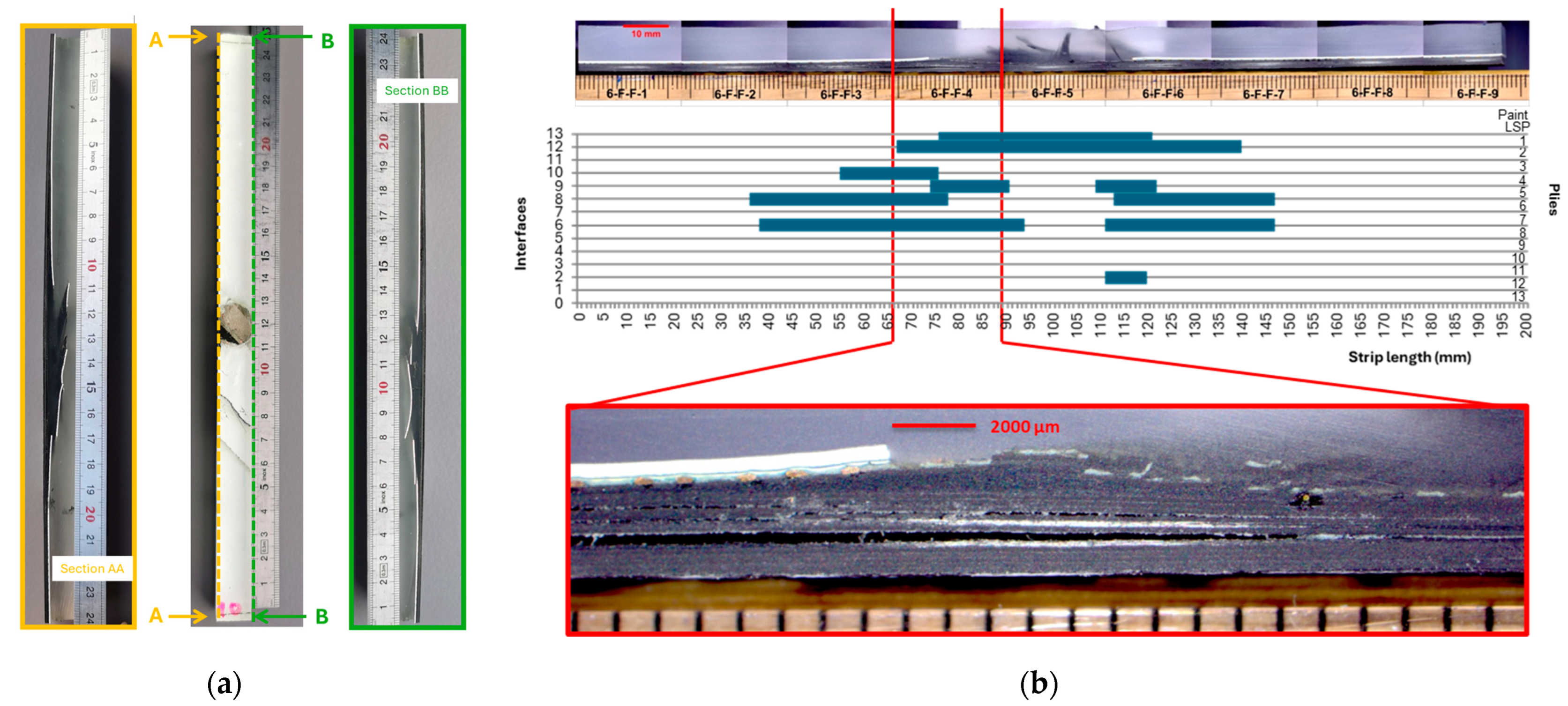
3.4. Two-Dimensional and 3D Delamination Mesurement from Cuttings

For each side AA and BB of the strips optical micrographic examinations are performed (Figure 10a). Because of the 2.2 mm thickness of the blade, each cut gives two different measures of delamination at one cut position. For example, face 1BB gives data that are different from face 2BB. A precision of 0.5 mm is chosen to sample the measure along the strip’s length. Measured delamination of each side as illustrated on Figure 10 is reported in a spreadsheet. The numbering of the interfaces begins from n°0 at the bottom face, to n°1 between plies 13 and 12, up to n°12 between plies 2 and 1, or even n°13 between ply 1 and the LSP.
A Matlab® home code has been developed to reconstruct the delamination profile per interface from the previously obtained spreadsheet file. It is now possible to reconstruct the 3D distribution of the core damage in the laminated after a lightning strike.
The profile is pixelated because of the strip width and blade thickness, and because of the 0.5 mm precision in the optical measures. But it provides accurate data on which interface is delaminated compared to ultrasonic scan. Indeed, NDT measurements can introduce some uncertainties in the position in depth and in discriminating the delaminated interface. This is particularly true for thin plies composite laminates as considered here, due to residual deformations and deflections of the bended plates (see right picture on Figure 9). Moreover, it is almost impossible to evaluate the influence of the cutting process on spurious delamination extension because as mentioned previously it is not possible to have precise measurements from non-destructive C-Scans for interfaces before cutting. Delamination in the interfaces close to the top face are partially or even totally hidden by larger delamination located near the bottom face of the laminate that are closer to the ultrasonic C-Scan probe. It is emphasized that this extension in the interface plan, if it exists, is not larger than the precision of measure of 0.5 mm at each interface.

4. Results and Discussion

As presented in Section 2, the core current flow is expected to have two different influences: the modification of the composite panel macroscopic mechanical properties due to thermal damage and the contribution of the composite upper plies’ explosion in the mechanical loading [41]. The core damage, indeed, is mainly delamination, which is the mechanical damage under interest, and it is known as being mainly due to the mechanical load contribution generated by the surface explosion of the LSP (see for example [12]). The main question examined here is whether the contribution of the mechanical loading induced by the thermal loading is negligible, and what is the contribution of the paint. These two effects are discussed in the two following paragraphs.

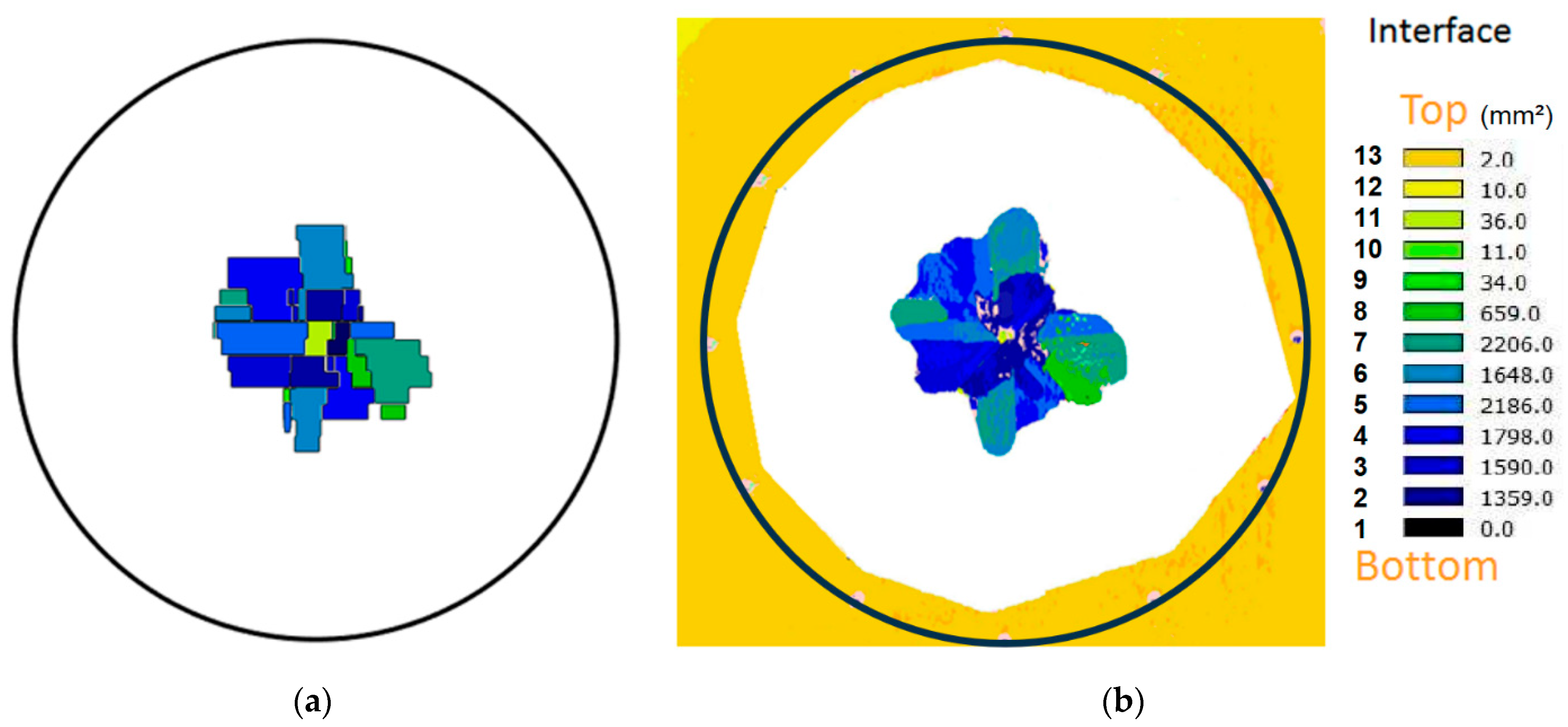
4.1. Two-Dimensional and 3D Delamination Reconstruction Result

The comparison of 2D top views of delamination for the sample 1 plate, which is the baseline sample as shown in Figure 11. The round black circle represent represents the position of the clamping bolts and serves as a scale for comparison.
With this method, the hidden delamination can be measured as illustrated in Figure 12. The delaminated surfaces from NDT C-Scans are in colour, and the remaining delaminated surface is obtained thanks to the reconstruction, which is added in grey. The left histogram is an obvious illustration of the missed information produced by NDT compared to the 3D reconstruction allowed by the micro-cuts.
Micro-cuts can also provide the volume of burned zones due to current flow in the CFRP, generating Joule heating (not presented here). With the micro-cuts, we have a complete view of the damage: internal damage in the plies and delamination at the interfaces.

4.2. Core Current Flow-Induced Damage

If delamination is mainly initiated by a 3D shock wave coming from the LSP explosion, thermal damage occurs at the same time. This means that, in particular, the mechanical rigidity of the plate could non-linearly be affected by the destruction of the matter (thermal damage due to thermal source), which could be itself the source of simultaneously generated new shock pressures. Therefore, delamination could have multiple initiating mechanical shocks sources and simultaneously potentially propagate due to the plate deflection under the shocks. In this paragraph, the study of the damage extent measurement due to this thermal source is used to help understanding the current distribution into the composite depth depending on the presence of LSP and/or of paint.
A thick paint applied on a composite structure constrains the arc expansion as previously explained, forcing the lightning current to flow deeper in the composite than with a thinner coating as long as the paint remains attached to the laminate. In Figure 13 below, the plies damaged by the current flow are visible thanks to a micro-cut performed in the centre of the laminate width. The first remaining but highly damaged ply in the centre is ply 5. Ply 1, corresponding to the first composite ply below the LSP, is destroyed, and ply 2 is highly damaged. Even with this very severe configuration where the arc root is highly constrained due to 1000 µm of covering paint, the deepest ply burned is ply 4 among the 13 composite plies of the panel. This represents a depth of penetration of about 508 µm compared to a total thickness of 1.65 mm. This configuration is considered extreme since 1000 µm of paint is not expected on an aircraft, where the usual thickness is between 250 µm and 400 µm. For these usual configurations, only the first ply is burned. It is, therefore, not expected to significantly change the mechanical rigidity of the plate.
Due to the high electrical resistance of the composite, the current penetrates locally in the depth of the laminate but soon after flows back to the surface metallic protection. The thermal damage is, therefore, highly localized even for a severe configuration as shown in Figure 14 and in the following paragraph. Nonetheless, as it deteriorates the resin and explodes the CFRP ply, some delamination in the top plies may be due to the current flow and not to the mechanical load.
It has been shown that some current can flow into the depth and reach the top CFRP plies. Recent studies have demonstrated that the glass ply below the LSP limit the core current by maintaining the current in the LSP [42], which reduces the thermal damage to the upper layers [4]. To study the thermal damage due to the current flow in the composite top plies, a lightning test was performed on an unprotected CFRP structure, and on a protected GFRP structure. In the first case, there is no diversion of the current because there is no LSP, and so all the current will flow into the composite. In the second case, as shown in [30], the glass fibres cannot conduct the current so that non explosion of fibre can be generated. The consumed surface of LSP is similar to a configuration where all the current flow in the LSP because of insulating properties of the panel (GFRP + LSP + paint sample 4). This means that the current diverted into the carbon structure is limited in depth and the Joule heating in the LSP, when present, is not modified by some loss in the top composite plies. As shown in Figure 15, only the shape of the vaporized LSP is modified as per the surface damage.
Since the lightning strike protection did divert most of the current, the total current (i.e., 100 kA) was not injected in this unprotected panel. In order to estimate the amount of current that can be injected into the composite top plies after the current is diverted by the LSP, some experimental tests have been realized on unprotected but painted panels with only a portion of current injected up to a maximum of a quarter of the total D-wave current. Even if the level of current in the composite cannot be measured, it is not expected to exceed such value. The following levels were considered: 5 kA, 13 kA and 25 kA. The damages from those different levels are presented in Figure 16.
It can be seen that the deepest depth of the delaminated interfaces increases with the current. But the extension of the delamination global surface remains very limited compared to a protected and painted configuration, which suffers a 100 kA full D-wave. In Figure 17, the delamination measurement on the worst configuration with 25 kA is presented up to the 6th ply from the top surface (i.e., the 5th interface) since there is no delamination deeper in the laminate for this unprotected configuration. Thanks to micro-cuts performed following the methodology of Section 3.3, the distribution of the delamination at each interface has been reconstructed. Delamination is very limited in extent and occurs mainly at the first two nearest interfaces from top face (n°11 and n°12). The first top delamination between plies 1 and 2 is only due to thermal stress from the current flow. Comparing this damage to our reference, i.e., a paint structure protected with ECF195 but tested at 100 kA, the reference one is much more severe (wider and deeper) and envelops the internal thermal damage, which is due to core current flow.
For a composite structure protected with ECF195 up to a baseline paint thickness (400 µm), the thermal stress due to the current flow in the composite is negligible and a mechanical model with a pressure load on its surface can be used for the prediction of the damage. This point has been investigated in [41]. This approach is not valid if the thermal damage is observed deeper in the laminate, possibly up to puncture. In this case, indeed, it will significantly modify the panel mechanical bending stiffness because of matter erosion. Furthermore, as observed in [43], when a puncture occurs during a lightning strike, it is observed after few microseconds. This early perforation can only be due to the electrothermal effect of the lightning core current flowing through the laminate in a very narrow area, as the mechanical effect due to surface explosion is slower than Joule heating that will destroy the fibres and the resin in this region only.

4.3. Core Current Flow-Induced Mechanical Load

The mechanism of the damage in the composite can be attributed to the explosion of the metallic protection on the surface but there is also an explosion of the composite at the same time. This second contributor was assessed in [41] thanks to a comparative study of the panel displacement with Digital Image Correlation during a lightning test. Since the pressure generated by a lightning strike cannot be directly measured, a study was performed on Glass Fibre Reinforced Panels. These non-conductive panels were used as a substrate of two kinds of targets. Some were covered with a CFRP ply 1 (127 µm), some not. All panels were protected with LSP, and 400 µm of paint. The deflections measured without and with the CFRP ply on top were very similar. It was, therefore, concluded that the contribution of the composite explosion can be neglected in the configuration with this LSP and 400 µm of paint. The core current flow is considered as a negligible contributor to the whole mechanical load. This hypothesis is applicable when the explosion remains limited to the first top plies as shown in Section 4.2. If thermal damages with broken fibres is observed deeper in the laminate, in a worst case up to the puncture, internal explosion may not be negligible anymore.

4.4. Mechanical Damage Extension Due to Surface Explosion: Paint Effect

Based on the previous frame define, we analyze hereafter the effect of the paint on the delamination. In this frame, the main source of delamination comes from the mechanical load due to the explosion of the LSP on the surface.
It is shown on Figure 18 that the total delaminated surface increases with increasing paint thickness, even with a lightning strike protection. Without any paint, the LSP fulfils its function perfectly and is only vaporized by Joule heating at the surface. In this configuration, there is no mechanical damage to the composite structure. With the presence of paint, damage in the composite can be observed. Figure 18 illustrates this mechanism for ECF195 protecting 1.6 mm thick CFRP plates. The total projected delaminated area obtained from NDT measurements is provided for each configuration.
Thanks to the destructive measurement method explained in Section 3.3, we can reconstruct a top view and a 3D view as shown in Figure 19 and study the damage at each interface as shown in Figure 20 below.
This method is very useful to study in more detail the damage within the laminate but presents some limits when the damages are very small. The configuration with 250 µm of paint has developed small delamination per interface and, therefore, the damages map is not accurate. Still, with this study, it is clearly visible that the delamination expands per interface but also its distribution in depth is different when the paint thickness increase.
In Section 4.2 and Section 4.3, it has been shown that thanks to the LSP layer, the current flow damage is limited to the first top plies. Even the thermal-mechanical shock load that is produced by the current in the first plies, when limited to them, has a negligeable effect on the damage. The 3D reconstruction of delamination illustrated on Figure 19 shows that damage of the first plies is thermal damage, and the position of the largest delamination, which is a mechanical damage, becomes closer to the top face when the thickness of paint increases. It is concluded that the mechanical overpressure generated on the panel comes from the shock produced by the LSP explosion and will increase with the paint thickness. The metallic gas and composite pyrolysis products cannot expand freely in air due to the presence of the paint on the top. This will slow down the pressure decay and globally increase the space–time overpressure profile. This phenomenon has been observed in numerical simulation and are correlated with experimental observations after lightning strikes on bare composites [44].

5. Conclusions

In this paper, a description of the damages in the composite due to lightning strike was presented and studied. There are two main types of damages: thermal damage (resin deterioration and fibre breakage) and mechanical damage (delamination). Thanks to the presence of the lightning strike protection layers, thermal damage can be restricted to the few upper plies of the composite laminate. However, the presence of added paint above it has a detrimental effect by making these damage dive into the laminate thickness and by increasing drastically the total delamination. Delamination is a mechanical damage generated by shocks that take their origin, during lightning strike, in the vaporization of the ECF and resin of the LSP layer and in the explosion of the carbon fibres in which the lightning current circulates. The question that has been asked in this article is to what extent the paint modifies the proportion of the contribution of the thermomechanical shock produced by the surface explosion to that of the shocks produced by the explosion of the fibres due to the flow of current to the core, on the extent and depth distribution of the delamination. The work presented in this paper has proposed a framework to study the contribution of surface explosion, independent of the current flow of the core. The analysis of the damage on unprotected structure demonstrated that a limited amount of current was flowing in the carbon composite plies close to the top face. Therefore, it is possible to neglect this current diversion and consider the total electrical energy as being injected into the surface lightning strike protection. In addition, when the damage due to the thermal source is limited to the first ply, it is possible to neglect this contribution and again consider only a mechanical source at the origin of delamination. Also, the mechanical contribution of the composite explosion due to the core current flow was demonstrated negligible compared to the surface explosion. Finally, thanks to an original method based on material cross-section, it was possible to study the delamination for all interfaces between very thin plies of plates that furthermore presented a residually curved shape. Since the plates studied here are covered by an elastomeric paint and an LSP containing a metallic mesh C-Scan images were obtained only from the bottom face observations. For situations with thick paint layer, this single side NDT can provide incomplete measure of distant delamination surfaces that are hidden by closer and larger ones. One of our main conclusions is that the paint confines the surface explosion, enhancing the mechanical loading. A comparative study of an identical configuration of 1.6 mm of CFRP, protected with ECF195, but different paint thicknesses demonstrated its detrimental effect. Also, the records of the damage per interface are very useful data in order to validate a mechanical damage model. This is the next step for our study.

Author Contributions

The contributions are as follows: Conceptualization, A.B., C.E., and J.-M.B.; Methodology, A.B., C.E., and J.-M.B.; Software, A.B., C.E., and J.-M.B.; Validation, A.B., C.E., and J.-M.B.; Formal analysis, A.B., C.E., and J.-M.B.; Investigation, A.B., C.E., and J.-M.B.; Resources, A.B., C.E., and J.-M.B.; Data curation, A.B., C.E., and J.-M.B.; Writing—original draft preparation, A.B., C.E., and J.-M.B.; writing—review and editing A.B., C.E., and J.-M.B.; Visualization, A.B., C.E., and J.-M.B.; Supervision, A.B., C.E., and J.-M.B.; Project administration, A.B., C.E., and J.-M.B.; Funding acquisition, A.B., C.E., and J.-M.B. All authors have read and agreed to the published version of the manuscript.

Funding

This research was funded by AIRBUS Sas, ISAE-SUPAERO, and the University of Orléans, and hosted by the ICA UMR CNRS and GREMI UMR CNRS laboratories.

Data Availability Statement

The original data of the lightning tests are not shared.

Acknowledgments

Lightning tests have been performed by Airbus (Toulouse, France) and DGA-Ta (Toulouse France). Works and results presented in this paper have been performed in the frame of a Ph.D., funded as described above. It has been held in collaboration between Airbus Sas, ISAE-SUPAERO/ICA, and the University of Orléans/GREMI. All the administrative and technical staffs of these institutions are thanked for their contribution to this work.

Conflicts of Interest

The authors declare no conflicts of interest. The funders had no role in the design of the study; in the collection, analyses, or interpretation of data; in the writing of the manuscript; or in the decision to publish the results.

References

  1. Feraboli, P.; Miller, M. Damage resistance and tolerance of carbon/epoxy composite coupons subjected to simulated lightning strike. Compos. Part A Appl. Sci. Manuf. 2009, 40, 954–967. [Google Scholar] [CrossRef]
  2. Hirano, Y.; Yokozeki, T.; Ishida, Y.; Goto, T.; Takahashi, T.; Qian, D.; Ito, S.; Ogasawara, T.; Ishibashi, M. Lightning damage suppression in a carbon fiber-reinforced polymer with a polyaniline-based conductive thermoset matrix. Comp. Sci. Tech. 2016, 127, 1–7. [Google Scholar] [CrossRef]
  3. Matsuo, S.; Sottos, N.R. Single carbon fiber transverse electrical resistivity measurement via the van der Pauw method. J. Appl. Phys. 2021, 130, 115105. [Google Scholar] [CrossRef]
  4. Yousefpour, K.; Lin, W.; Wang, Y.; Park, C. Modeling Discharge and ground electrode design considerations for the lightning strike damage tolerance assessment of CFRP matrix composite laminates. Compos. Part B Eng. 2020, 198, 108226. [Google Scholar] [CrossRef]
  5. Duongthipthewa, A.; Tian, Y.; Duongthipthewa, O.; Su, Z.; Zhou, L. A comprehensive analysis of electric, thermal, and structural effects of lightning strikes on CFRP composites and protective strategies. Comp. Comm. 2023, 44, 101739. [Google Scholar] [CrossRef]
  6. Li, S.; Sun, J.; Guo, Y.; Li, Y.; Wang, B.; Zhu, Y.; Li, M.; Yao, X. Analysis of the damage effects of carbon fiber composites under the mechanical impact loads of lightning based on a modified simulation calculation method. Compos. Part B Eng. 2024, 238, 111644. [Google Scholar] [CrossRef]
  7. Das, S.; Yokozeki, T. A brief review of modified conductive carbon/glass fibre reinforced composites for structural applications: Lightning strike protection, electromagnetic shielding, and strain sensing. Compos. Part C Open Access 2021, 5, 100162. [Google Scholar] [CrossRef]
  8. Munoz, R.; Delgado, S.; Gonzalez, C.; Lopez-Romano, B.; Wang, D.-Y.; LLorca, J. Modeling Lightning Impact Thermo-Mechanical Damage on Composite Materials. Appl. Compos. Mater. 2014, 21, 149–164. [Google Scholar] [CrossRef]
  9. Kumar, V.; Lin, W.; Wang, Y.; Spencer, R.; Saha, S.; Park, C.; Yeole, P.; Hmeidat, N.S.; Herring, C.; Rencheck, M.L.; et al. Enhanced through-thickness electrical conductivity and lightning strike damage response of interleaved vertically aligned short carbon fiber composites. Compos. Part B Eng. 2023, 253, 110535. [Google Scholar] [CrossRef]
  10. Chemartin, L.; Lalande, P.; Peyrou, B.; Chazottes, A.; Elias, P.Q.; Delalondre, C.; Cheron, B.G.; Lago, F. Direct Effects of Lightning on Aircraft Structure: Analysis of the Thermal, Electrical and Mechanical Constraints. AerospaceLab 2012, 5, 1–15. [Google Scholar]
  11. Jia, A.; Wang, F.; Xu, B.; Yan, W. A developed energy-dependent model for studying thermal shock damage and phase transition of composite reinforced panel subjected to lightning strike. Eur. J. Mech.—A/Solids 2021, 85, 104141. [Google Scholar] [CrossRef]
  12. Wang, Y.; Fan, Y.; Zhupanska, O.I. Challenges and Future Recommendations for Lightning Strike Damage Assessments of Composites: Laboratory Testing and Predictive Modeling. Materials 2024, 17, 744. [Google Scholar] [CrossRef]
  13. EUROCAE. ED-84; Aircraft Lightning Environment and Related Test Waveforms. GlobalSpec: Saint-Denis, France, 2013. Available online: https://www.eurocae.net/product/ed-84a-aircraft-lightning-environment-and-related-waveforms/ (accessed on 12 May 2025).
  14. Hirano, Y.; Katsumata, S.; Iwahori, Y.; Todoroki, A. Artificial lightning testing on graphite/epoxy composite laminate. Compos. Part A Appl. Sci. Manuf. 2010, 41, 1467–1470. [Google Scholar] [CrossRef]
  15. Li, Y.; Li, R.; Lu, L.; Huangv, X. Experimental study of damage characteristics of carbon woven fabric/epoxy laminates subjected to lightning strike. Compos. Part A Appl. Sci. Manuf. 2015, 79, 164–175. [Google Scholar] [CrossRef]
  16. Sun, J.; Yao, X.; Tian, X.; Chen, J.; Wu, Y. Damage Characteristics of CFRP Laminates Subjected to Multiple Lightning Current Strike. Appl Compos Mater 2019, 26, 745–762. [Google Scholar] [CrossRef]
  17. Abdelal, G.; Murphy, A. Nonlinear numerical modelling of lightning strike effect on composite panels with temperature dependent material properties. Comp. Struc. 2014, 109, 268–278. [Google Scholar] [CrossRef]
  18. Karch, C.; Honke, R.; Steinwandel, J.; Dittrich, K.W. Contributions of lightning current pulses to mechanical damage of CFRP structures. In Proceedings of the International Conference on Lightning & Static Electricity (ICOLSE 2015), Toulouse, France, 9–11 September 2015. [Google Scholar] [CrossRef]
  19. Foster, P.; Abdelal, G.; Murphy, A. Understanding how arc attachment behaviour influences the prediction of composite specimen thermal loading during an artificial lightning strike test. Comp. Struc. 2018, 192, 671–683. [Google Scholar] [CrossRef]
  20. Soulas, F.; Espinosa, C.; Lachaud, F.; Guinard, S.; Lepetit, B.; Revel, I.; Duval, Y. A method to replace lightning strike tests by ball impacts in the design process of lightweight composite. Int. J. Imp. Eng. 2018, 111, 165–176. [Google Scholar] [CrossRef]
  21. Dong, Q.; Guo, Y.; Chen, J.; Yao, X.; Yi, X.; Ping, L.; Jia, Y. Influencing factor analysis based on electrical–thermal-pyrolytic simulation of carbon fiber composites lightning damage. Comp. Struc. 2016, 140, 1–10. [Google Scholar] [CrossRef]
  22. Karch, C.; Metzner, C. Lightning protection of carbon fibre reinforced plastics—An overview. In Proceedings of the 33rd International Conference on Lightning Protection (ICLP 2016), Estoril, Portugal, 25–30 September 2016. [Google Scholar] [CrossRef]
  23. Gagné, M.; Therriault, D. Lightning strike protection of composites. Prog. Aerosp. Sci. 2014, 64, 1–16. [Google Scholar] [CrossRef]
  24. Bigand, A.; Duval, Y. Quantification of the mechanical impact of lightning strike protection explosion confined by thick paint. In Proceedings of the International Conference on Lightning & Static Electricity (ICOLSE 2017), Winc Aichi, Nagoya, Aichi, Japan, 13–15 September 2017; Available online: https://hal.science/hal-03234731/document (accessed on 12 May 2025).
  25. Yi, X. Research on lightning protection metal mesh for wind turbine blades. In Proceedings of the 2nd International Conference on Sustainable Technology and Management (ICSTM 2023), Dongguan, China, 21–23 July 2023. [Google Scholar] [CrossRef]
  26. Russ, M.; Rahatekar, S.; Koziol, K.; Peng, H.X.; Farmer, B. Development of carbon nanotube/epoxy nanocomposites for lightning strike protection. In Proceedings of the 18th International Conference on Composite Materials (ICCM), Jeju, Republic of Korea, 21–26 August 2011; Available online: https://research-information.bris.ac.uk/en/publications/development-of-carbon-nanotubeepoxy-nanocomposites-for-lightning- (accessed on 12 May 2025).
  27. Kumar, V.; Yokozeki, T.; Karch, C.; Hassen, A.A.; Hershey, C.J.; Kim, S.; Lindahl, J.M.; Barnes, A.; Bandari, Y.K.; Kunc, V. Factors affecting direct lightning strike damage to fiber reinforced composites: A review. Compos. Part B Eng. 2020, 183, 107688. [Google Scholar] [CrossRef]
  28. Guo, Y.; Xu, Y.; Wang, Q.; Dong, Q.; Yi, X.; Jia, Y. Enhanced lightning strike protection of carbon fiber composites using expanded foils with anisotropic electrical conductivity. Compos. Part A Appl. Sci. Manuf. 2019, 117, 211–218. [Google Scholar] [CrossRef]
  29. Sousa Martins, R. Experimental and Theoretical Studies of Lightning Arcs and Their Interaction with Aeronautical Materials. Ph.D. Thesis, Université PARIS-SACLAY, Paris, France, 2016. Available online: https://hal.science/tel-01434026v1 (accessed on 12 May 2025).
  30. Bigand, A.; Espinosa, C.; Bauchire, J.-M. Lightning surface explosion impact study on damage generation into composite. In Proceedings of the International Conference on Lightning & Static Electricity (ICOLSE 2019), Wichita Area Technical College, Wichita, KS, USA, 10–13 September 2019; Available online: https://hal.science/hal-02391647 (accessed on 12 May 2025).
  31. Espinosa, C.; Bhoosnurmath, H.; CLópez, A.; Lachaud, F. Numerical Modelling of a Lightning Strike on a Protected Composite Panel. In Proceedings of the International Conference on Lightning & Static Electricity (ICOLSE 2017), Winc Aichi, Nagoya, Aichi, Japan, 13–15 September 2017; Available online: https://hal.science/hal-02044384v1/document (accessed on 14 May 2025).
  32. Lepetit, B.; Escure, C.; Guinard, S.; Revel, I.; Peres, G. Thermo-mechanical effects induced by lightning on carbon fiber composite materials. In Proceedings of the International Conference on Lightning and Static Electricity (ICOLSE 2011), Oxford, UK, 6–9 September 2011; Available online: https://api.semanticscholar.org/CorpusID:210910432 (accessed on 14 May 2025).
  33. Bigand, A.; Espinosa, C.; Bauchire, J.-M.; Flourens, F.; Lachaud, F. Lightning damage assessment into composite based on surface explosion and fiber breakage. In Proceedings of the 22nd International Conference on Composite Materials (ICCM2), Melbourne, Australia, 11–16 August 2019; Available online: https://hal.science/hal-02392778v1 (accessed on 12 May 2025).
  34. Millen, S.L.J.; Ashworth, S.; Farrell, C.; Murphy, A. Understanding and representing heating and heating rate effects on composite material properties for lightning strike direct effect simulations. Compos. Part B Eng. 2022, 228, 109438. [Google Scholar] [CrossRef]
  35. Li, S.; Wang, A.; Sun, J.; Jiang, Z.; Guo, Y.; Yao, X. Quantitative Experimental Study of Mechanical Effects of Carbon Fiber Composites under Impulse Lightning Current. In Proceedings of the 2024 IEEE International Conference on High Voltage Engineering and Applications (ICHVE 2024), Berlin, Germany; 2024; pp. 1–3. [Google Scholar] [CrossRef]
  36. Lepetit, B.; Soulas, F.; Guinard, S.; Revel, I.; Peres, G. Analysis of composite panel damages due to a lightning strike: Mechanical effects. In Proceedings of the International Conference on Lightning & Static Electricity (ICOLSE 2013), Seattle, WA, USA, 18–20 September 2013. [Google Scholar]
  37. Rannou, J.; Huchette, C.; Hurmane, A.; Tholin, F. An analysis of lightning direct effects on CFRP panels. Part II, the electro-thermo-mechanical simulation strategy. In Proceedings of the International Conference on Lightning & Static Electricity (ICOLSE 2017), Winc Aichi, Nagoya, Aichi, Japan, 13–15 September 2017. [Google Scholar]
  38. Huchette, C.; Rannou, J.; Roche, J.; Lapeyronnie, P.; Beauchêne, P.; Chemartin, L. An analysis of lightning direct effects on CFRP panels. Part I, the experimental and material point of view. In Proceedings of the International Conference on Lightning & Static Electricity (ICOLSE 2017), Winc Aichi, Nagoya, Aichi, Japan, 13–15 September 2017. [Google Scholar]
  39. Bigand, A.; Bauchire, J.-M.; Espinosa, C. Lightning arc interaction with complex structure. In Proceedings of the 15th International High-Tech Plasma Processes Conference (HTPP), Toulouse, France, 2–6 July 2018; Available online: https://hal.science/hal-02152731 (accessed on 12 May 2025).
  40. EUROCAE. ED-105; Aircraft Lightning Test Methods. GlobalSpec: Albany, NY, USA, 2013. Available online: https://standards.globalspec.com/std/1637778/eurocae-ed-105 (accessed on 12 May 2025).
  41. Bigand, A.; Espinosa, C.; Bauchire, J.-M. Equivalent mechanical load model methodology to simulate lightning strike impact on protected and painted composite structure. Electr. Power Syst. Res. 2023, 217, 114886. [Google Scholar] [CrossRef]
  42. Guo, Y.; Xu, Y.; Zhang, L.; Wei, X.; Dong, Q.; Yi, X.; Jia, X. Implementation of fiberglass in carbon fiber composites as an isolation layer that enhances lightning strike protection. Comp. Sci. Tech. 2019, 174, 117–124. [Google Scholar] [CrossRef]
  43. Bigand, A.; Revel, I.; Hascoet, V.; Nacelles, S. Lightning current transfer risk assessment after skin puncture. In Proceedings of the International Conference on Lightning & Static Electricity (ICOLSE 2019), Wichita Area Technical College, Wichita, KS, USA, 10–13 September 2019. [Google Scholar]
  44. Guo, Y.; Dong, Q.; Chen, J.; Yao, X.; Yi, X.; Jia, Y. Comparison between temperature and pyrolysis dependent models to evaluate the lightning strike damage of carbon fiber composite laminates. Compos. Part A Appl. Sci. Manuf. 2017, 97, 10–18. [Google Scholar] [CrossRef]
Figure 1. Common Lightning Strike Protections metallic foils [24] and delamination comparison produced by waveform D on identical CFRP panels covered by 400 µm of paint between (a) the ECF195 from Dexmet Cie (now PPG Industries Ohio (Cleveland, OH, USA)) and (b) continuous SCF in which typical thickness is 10 to 20 µm (b). Colours in the images correspond to the depth of the obstacle, indeed delamination, obtained classically by C-Scan measurements (see Section 3.3 for details).
Aerospace 12 00446 g001
Figure 2. Unprotected composite damage evolution with paint, front view (top row) and back view (bottom row).
Aerospace 12 00446 g002
Figure 3. Examples of Surface cosmetic (red) or structural (green) damage.
Aerospace 12 00446 g003
Figure 4. Core lightning damage at the centre of a 13 CFRP plies of 127 µm thickness each covered by ECF195 and 400 µm of paint impacted by a 100 kA D-waveform [33].
Aerospace 12 00446 g004
Figure 5. Lightning damage source decomposition: 1st (red circle) the surface explosion creating a mechanical load, and 2nd (green circle) the thermal shock produced by the current injection in the composite plies.
Aerospace 12 00446 g005
Figure 6. Schematic representation of the electrode-sample positioning during laboratory lightning tests [40] (a) and right: global set-up available at DGA-Ta [20] (b).
Aerospace 12 00446 g006
Figure 7. Example of resin plot application and typical dimensions (top view of sample 1).
Aerospace 12 00446 g007
Figure 8. Strips cutting scheme (a) drawn on the resin plot to guide the cutting blade path (narrow top view of sample 1) and (b) representation superposed on the C-Scan delamination measurement. The choice of the strip width of 14 mm is a trade-off between choosing small strips to increase the precision and large strips to avoid residual damage to the cut trips during or after cutting.
Aerospace 12 00446 g008
Figure 9. (Left) and (middle): cutting process (sample 2); (right): cut strip with frozen damaged components embedded in the resin plot. Residual deflection of the panel is visible on the right picture.
Aerospace 12 00446 g009
Figure 10. Micrographic inspection and delamination record example: (a) picture of the two sides from one strip, and (b) measurement methods using optical microscope (sample 1).
Aerospace 12 00446 g010
Figure 11. Comparison of (a) destructive delamination surface reconstruction comparison with (b) NDT result for sample 2 laminate (black circle = schematic representation of the boundary conditions made of 12 bolts connected to an annular metallic frame).
Aerospace 12 00446 g011
Figure 12. Reference case: Delamination distribution obtained with destructive measurements are visible in colour, each colour being related to an interface. Grey histograms are delamination not visible on C-Scan global delaminated surface observations hidden by closer delamination.
Aerospace 12 00446 g012
Figure 13. Internal damage study for severe configuration: CFRP (13 plies) + ECF195 + 1000 µm of paint (sample 2).
Aerospace 12 00446 g013
Figure 14. Internal damage study for severe configuration: CFRP (13 plies) + ECF195 + 1000 µm of paint (sample 2): top view (left) and side view (right).
Aerospace 12 00446 g014
Figure 15. Vaporization profile on (a) GFRP (sample 4) vs. (b) CFRP (sample 1).
Aerospace 12 00446 g015
Figure 16. Delamination study for unprotected structure (CFRP (13 plies) + 400 µm of paint with no LSP layer, samples 5, 6 and 7 from left to right).
Aerospace 12 00446 g016
Figure 17. Delamination distribution from NDT and cuttings for the same CFRP structure left = NDT/top = cuttings from painted with 400 µm and unprotected hit by 25 kA (sample 7), right = NDT/bottom = cuttings painted with 400 µm protected with ECF195 hit by 100 kA (sample 1).
Aerospace 12 00446 g017
Figure 18. Lightning damage evolution with paint thickness increase.
Aerospace 12 00446 g018
Figure 19. Delamination total area view from top and 3D: left from NDT, right from cuttings.
Aerospace 12 00446 g019
Figure 20. Damage reconstruction per interface with different paint thicknesses from cuttings.
Aerospace 12 00446 g020
Table 1. Summary of experimental configurations under interest.
RationaleN° SampleLSPPaint Thickness (µm)Peak Current kA
CFRP Composite damage baseline1ECF195400100
CFRP Composite damage with internal explosion and extreme surface confinement2ECF1951000100
CFRP Composite damage with internal explosion and light surface confinement3ECF195250100
Thermal damage due to full current in the LSP and no current in the GFRP4ECF195400100
CFRP Composite thermal damage produced by current diving from top ply5No4005
CFRP Composite thermal damage produced by current diving from top ply6No40013
CFRP Composite thermal damage produced by current diving from top ply7No40025
Disclaimer/Publisher’s Note: The statements, opinions and data contained in all publications are solely those of the individual author(s) and contributor(s) and not of MDPI and/or the editor(s). MDPI and/or the editor(s) disclaim responsibility for any injury to people or property resulting from any ideas, methods, instructions or products referred to in the content.

