1. Introduction
The aviation industry is undergoing a transformative shift towards more efficient and environmentally friendly solutions. High-speed aircrafts capable of significantly reducing travel time have gathered considerable attention from both academic communities and industries. Green transonic and supersonic aircrafts represent a critical direction for the future development of civil aviation, offering not only faster travel but also addressing the pressing need for sustainable flight technologies. Enhancing aerodynamic performance in transonic and supersonic conditions is pivotal to achieving green and sustainable aviation, as it can lead to reduced fuel consumption, lower emissions, and improved operational efficiency.
Aerodynamic shape optimization plays a crucial role in this endeavor. Traditional methods for designing airfoils have relied on iterative wind tunnel testing and empirical adjustments, which are not only costly and time-consuming but also limited by their reliance on designer experience. The advent of advanced computational tools, particularly computational fluid dynamics (CFD), has revolutionized the field. CFD-based numerical optimization methods have become indispensable for achieving better aerodynamic performance in aircraft design.
However, the complexity and nonlinearity of aerodynamic optimization problems pose significant challenges that traditional methods struggle to address effectively. This is where reinforcement learning (RL) emerges as a powerful alternative [
1,
2,
3,
4]. RL offers a dynamic approach that can learn from interactions with complex environments, making it highly suitable for tackling the intricate problems associated with airfoil aerodynamic design. Unlike traditional optimization methods that require predefined rules or extensive simulations, RL enables the development of adaptive strategies that improve over time through trial and error, guided by rewards that reflect desired outcomes.
Several pioneering studies have demonstrated the potential of RL in aerodynamic optimization. Yonekura et al. [
5] introduced a deep reinforcement learning (DRL) framework for optimizing wing angles in 2D, steady, incompressible flows, highlighting DRL’s generalization ability. Viquerat et al. [
6] extended DRL to shape optimization, showing that well-crafted reward functions enable agents to autonomously produce optimal shapes. Li et al. [
7] incorporated physical attributes like shock wave position and peak suction Mach number into state variables for supercritical airfoil design, achieving drag minimization via a Hicks–Henne function controlled by three parameters. Dussauge et al. [
8] modeled airfoil optimization as a Markov decision process (MDP) by using neural networks to approximate values and policy functions, which improved learning efficiency. Liu et al. [
9] proposed a multi-point DRL-based optimization framework for supercritical airfoils, integrating surrogate models to lower computational costs while managing complex constraints. Su et al. [
10] explored a deformable airfoil reverse design with Deep Q-Networks (DQNs), demonstrating its practicality compared to conditional generative adversarial networks (CGANs). Liu et al. [
11] applied an actor-critic algorithm to rotor wing optimization, improving lift coefficients and reducing drag and torque by addressing dynamic stall characteristics. These studies highlight RL’s transformative role in advancing aerodynamic optimization techniques for enhanced airfoil performance.
This paper explores the application of RL to optimize the design of transonic and supersonic airfoils. The proposed method introduces a RL-based framework for aerodynamic optimization, which differs fundamentally from traditional optimization techniques such as gradient-based or evolutionary algorithms. One of the key advantages of our approach lies in its ability to autonomously explore a broad design space without relying on explicit gradient information or population-based heuristics. This makes it particularly suitable for optimization problems commonly encountered in airfoil aerodynamic design. By leveraging RL, we aim to develop intelligent algorithms capable of efficiently navigating the complex space of aerodynamic design parameters. The focus is on creating a novel framework that integrates ADflow for aerodynamic simulations and CST parameters to describe airfoil geometry. This approach allows the RL model to iteratively refine designs based on real-time feedback from simulations. We investigate how this method can improve airfoil shapes under various flow conditions, with the goal of enhancing lift-to-drag ratios and reducing shock wave drag. This study will examine the effectiveness of RL in optimizing both transonic and supersonic airfoils.
2. Method
2.1. Aerodynamic Analysis Approach
The open-source code ADflow is used for aerodynamic analysis, which is a finite volume CFD solver for structured multiblock and overlapping grids [
12]. ADflow solves the compressible Euler equations, laminar Navier–Stokes equations, and Reynolds-averaged Navier–Stokes (RANS) equations with second-order accurate spatial discretization. It employs a variety of numerical methods to achieve robust and efficient convergence to steady-state solutions, including multigrid, approximate Newton–Krylov, and full Newton–Krylov algorithms. The integration of these iterative methods enhances ADflow’s performance, making it both robust and fast [
13,
14].
For validation, we performed a comparison study against experiments under specific flow conditions: a Mach number of Ma = 0.729 and a Reynolds number of Re = 6.5 × 10
6. The RANS equations and the Spalart–Allmaras turbulence model equation are solved on a converged grid.
Figure 1a shows the geometry of the RAE2822 airfoil, and the converged pressure coefficient distribution is given in
Figure 1b, where the curve located on the upper side represents the pressure coefficient distribution on the upper surface of the airfoil, and the curve located on the lower side represents the pressure coefficient distribution on the lower surface of the airfoil, from which it is known that the calculated results from ADflow in our study exhibit (the blue solid line) good agreement with the experimental data (the black X-shaped markers in
Figure 1b) [
15].
2.2. Geometric Parameterization
The Class-Shape Transformation (CST) method [
16] is utilized to parameterize the airfoil, which can represent the airfoil shape using Bernstein polynomials with relatively few parameters:
where
represents half the thickness of the trailing edge of the airfoil and
denotes the chord length of the airfoil. For a general airfoil, the parameters
and
are typically set to 0.5 and 1.0, respectively. The polynomial order is denoted by
, while
and
represent the CST parameters for the upper and lower surfaces of the airfoil, respectively.
In order to balance the accuracy of airfoil geometry description and the exploration scope of reinforcement learning, we select 10 CST coefficients as design variables for subsequent optimization methods based on reinforcement learning.
2.3. Reinforcement Learning
Reinforcement learning (RL) is an interactive learning paradigm in which an agent learns optimal behaviors by interacting with its environment [
17]. The agent selects actions based on the current state of the environment, observes the resulting outcomes, and receives rewards or penalties. Positive rewards reinforce beneficial actions, while negative rewards deter unfavorable ones. Over time, this iterative feedback loop enables the agent to develop strategies that maximize cumulative rewards, leading to improved decision-making and performance.
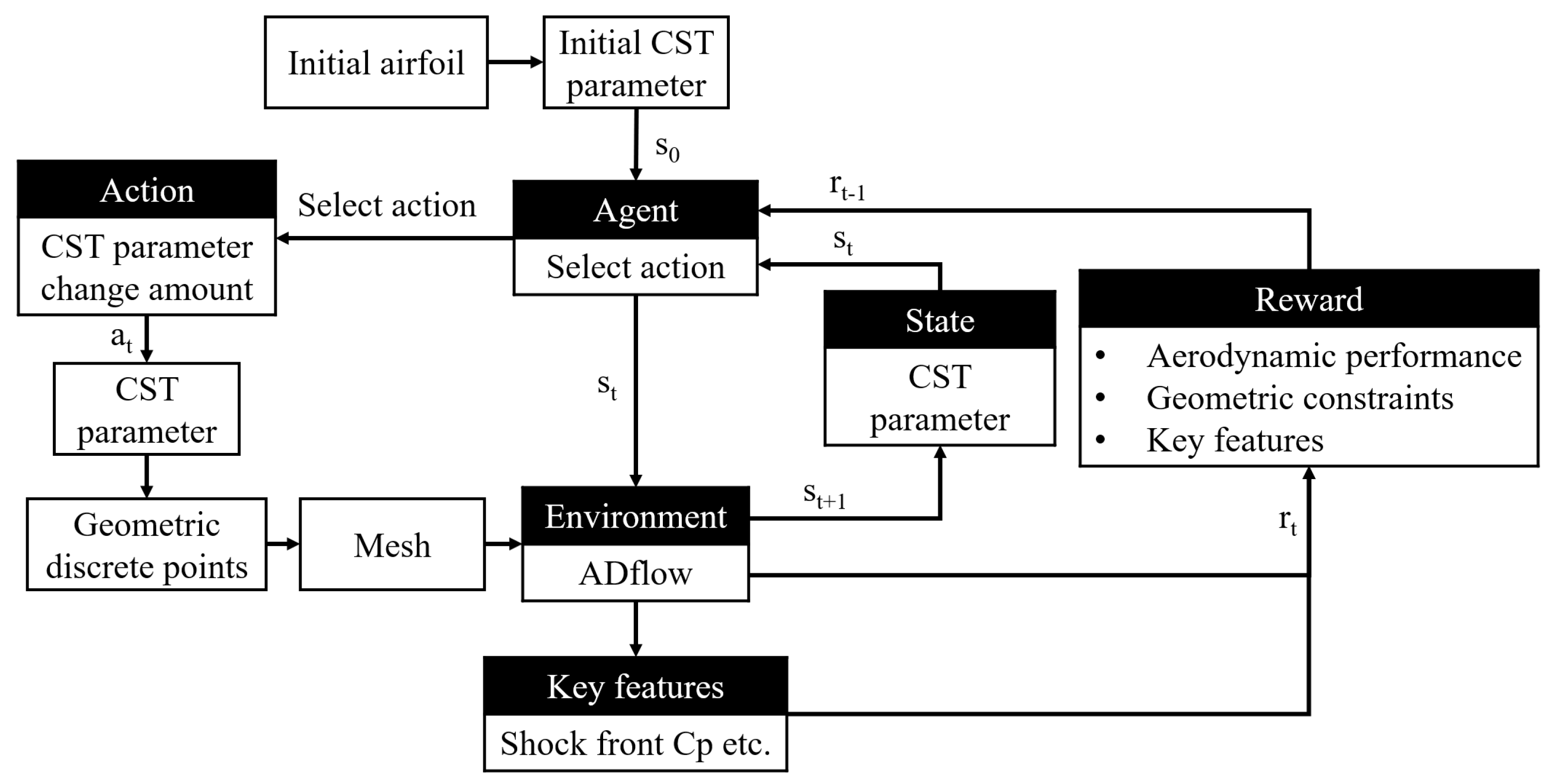
The RL process utilized in this paper can be summarized in
Figure 2. Firstly, we use the CST method to parametrize the airfoil, serving as the state of reinforcement learning, which constitutes the current state of the environment. Then, the intelligent agent generates new airfoils by modifying CST parameters to perform actions on the environment. After this operation, the aerodynamic performance of the modified airfoil is estimated via the RANS solver (ADflow), such as the lift-to-drag ratio (L/D) and flow field characteristics. These aerodynamic performance indicators serve as the basis for rewards. At the end, the score can be calculated based on the cumulative performance indicators of the airfoil generated at each iteration to estimate the overall performance of the agent.
3. Formulation of Optimization Problem
The performance of an airfoil is closely linked to its flow field. An effective airfoil design strategy relies on understanding the aerodynamic and flow characteristics of the airfoil, allowing for the development of solutions that can adapt to various operating conditions. Specifically, the physical properties of the flow field, particularly the pressure distribution on the airfoil surface, serve as critical factors for airfoil optimization, enabling more efficient design outcomes. These characteristics also enhance the interpretability of the design process for engineers. In our study, we aim to demonstrate how the flow field characteristics influence the optimization process in RL by incorporating the airfoil surface pressure coefficient into the reward function.
To achieve this, we selected several key features from the airfoil’s flow field as part of the RL reward function based on Ref. [
7], which includes three features, i.e., the pressure coefficient at the leading edge of the airfoil lower surface, the strength of the shock wave, and the minimum pressure coefficient on the airfoil’s upper surface.
To assess the impact of incorporating flow field features into the reward function, we compared the optimization performance of RL using these features against a baseline method without such features. For this analysis, we used the RAE2822 airfoil with the following conditions: a Mach number of Ma = 0.75 and a Reynolds number of Re = 6.4 × 10⁶. The goal was to maximize the lift-to-drag ratio at a fixed lift coefficient of CL = 0.50.
The overall optimization problem is formulated as follows:
Design objective: The design objective is to maximize the lift-to-drag ratio at a Mach number of Ma = 0.75, a Reynolds number of Re = 6.4 × 10⁶, and a lift coefficient of CL = 0.50.
Design variables: The airfoil CST coefficients are selected as design variables.
Design constraints: The design constraints include the maximum airfoil thickness and a target lift coefficient range to satisfy performance requirements. These constraints are embedded directly into the reward function or through penalties within the reinforcement learning framework.
Figure 3 shows the optimized airfoil geometry and the pressure coefficient distribution after optimization.
Table 1 summarizes the optimization results. As can be seen from the results, including flow field features in the reward function leads to superior optimization performance by reducing shock wave intensity, decreasing wave drag, and lowering the drag coefficient, thereby enhancing the lift-to-drag ratio.
4. Airfoil Aerodynamic Optimization Case Studies
4.1. Case Study for Different Initial Airfoils
To further explore the effectiveness of the RL-based optimization design, we selected two initial airfoils—RAE2822 and HQ2012—with a relative thickness of 12%. These airfoils were optimized under flight conditions of C
L = 0.5, Ma = 0.75, and Re = 6.4 × 10
6. The RL optimization method incorporated the three key flow field features discussed in
Section 3 while ensuring that the airfoil thickness is no less than the original value.
The comparison of airfoil geometry and pressure distribution before and after optimization is illustrated in
Figure 4.
Table 2 summarizes the optimization results, highlighting improvements in aerodynamic performance across all selected airfoils. The RL-based optimization method proved highly effective in improving the aerodynamic performance of the two selected airfoils, resulting in notable increases in the lift-to-drag ratio. From the pressure coefficient distributions, it is clear that RL optimization weakened the shock waves, leading to decreased drag and an increase in the lift-to-drag ratio. Notably, the HQ2012 airfoil showed a much more significant improvement, with a 70.20% increase in the lift-to-drag ratio. In comparison, the RAE2822 airfoil only shows an 18.17% improvement in the lift-to-drag ratio. The main reason is that the initial RAE2822 airfoil already possesses good transonic performance, so the optimization effect is not as significant as that of the HQ2012 airfoil.
4.2. Transonic Airfoil Optimization Results
We conducted aerodynamic analysis on the optimization results of the RAE2822 airfoil, which was previously optimized using RL, at different Mach numbers: 0.30, 0.75, 0.78, and 0.80. The aerodynamic polar graphs obtained from this analysis are presented in
Figure 5. The polar provides insights into how the optimized RAE2822 airfoil performs across a range of lift coefficients and Mach numbers. This analysis is crucial for understanding the robustness and versatility of the optimized design under varying flight conditions.
The RL-based optimization design for the RAE2822 airfoil shows significant aerodynamic performance improvements across various lift coefficients and Mach numbers. Starting with low-speed conditions such as takeoff and descent, at Ma = 0.30, the optimized airfoil achieved its maximum lift-to-drag ratio improvement at CL = 0.60, resulting in a modest yet meaningful 2.21% increase. This demonstrates that RL-based optimization enhances aerodynamic performance even during critical flight phases where efficiency is paramount. Moving into transonic conditions, at Ma = 0.75, the intended cruising Mach number, the optimized airfoil achieved its most substantial lift-to-drag ratio improvement at CL = 0.58, with a remarkable 26.22% increase, underscoring its exceptional performance under these conditions. At slightly higher transonic speeds, specifically Ma = 0.78, the maximum lift-to-drag ratio improvement was recorded at CL = 0.47, achieving a significant enhancement of 35.95%, indicating robust performance even as Mach numbers increase. Finally, at Ma = 0.80, despite challenges posed by more obvious shock waves, the optimized airfoil maintained substantial performance benefits, with a 26.98% gain in the lift-to-drag ratio at CL = 0.39. These findings highlight the versatility and effectiveness of the RL-based optimization method. The optimized RAE2822 airfoil not only achieves substantial improvements in the lift-to-drag ratio near its cruising Mach number but also demonstrates enhanced performance across a broader range of operating conditions. This comprehensive improvement highlights the potential of RL techniques to significantly advance airfoil design, offering better aerodynamic efficiency and adaptability for diverse flight scenarios.
4.3. Supersonic Airfoil Optimization Results
We applied the RL-based optimization design to the supersonic airfoil NASA SC(2)-0404 under conditions of C
L = 0.5, Ma = 1.40, and Re = 11.9 × 10
6. The optimization incorporated three key flow field features introduced earlier—pressure, coefficient, and shock wave—while ensuring the airfoil’s thickness remained above 4% to preserve structural integrity.
Figure 6 compares the airfoil’s geometry before and after optimization. RL effectively optimized the NASA SC(2)-0404 airfoil under supersonic conditions, resulting in key geometric modifications: decreased upper surface curvature, increased lower surface curvature, and a sharper leading edge. These changes led to a notable 6.25% increase in the lift-to-drag ratio, demonstrating the effectiveness of RL-based optimization in enhancing aerodynamic performance while addressing the unique challenges of supersonic aerodynamics.
To further analyze the optimization results, we examined the NASA SC(2)-0404 airfoil across a wide range of lift coefficients. The polar presented in
Figure 7 illustrates the relationship between lift and drag coefficients, providing comprehensive insights into the aerodynamic performance. Additionally,
Figure 8 shows the pressure coefficient distribution on the airfoil surface for selected lift coefficients, offering detailed visualizations of the improvements achieved through optimization. From
Figure 7 and
Figure 8, we can observe that the optimization results show varying degrees of improvements in the lift-to-drag ratio under different lift coefficients, while the changes in the pressure coefficient distribution exhibit similar trends. These analyses underscore the versatility and robustness of the RL-based method, highlighting its potential to significantly advance supersonic airfoil design by balancing aerodynamic efficiency with structural requirements.
5. Conclusions
In this paper we have studied the effectiveness and versatility of reinforcement learning (RL)-based optimization methods in enhancing aerodynamic performance for both transonic and supersonic airfoils. The main conclusions are summarized as follows.
We introduced a novel methodology using RL to optimize airfoil designs. This approach leverages ADflow as the aerodynamic solver and constructs an RL environment where CST parameters describe the airfoil’s geometry, transforming it into a finite state variable. Key flow field features, especially shock waves, were incorporated into the training process to guide the optimization. This framework enables the RL model to iteratively learn and improve airfoil designs based on real-time feedback from aerodynamic simulations, leading to significant performance improvements.
The application of RL-based optimization to transonic airfoils yielded remarkable results. We applied optimization to two initial airfoils—REA2822 and HQ2012—under flight conditions of CL = 0.5, Ma = 0.75, and Re = 6.4 × 10⁶. The optimized airfoils showed reduced upper surface curvature and more rounded leading edges, aligning with traditional transonic optimization practices. Across various initial airfoils, the method consistently improved lift-to-drag ratios, with one notable case achieving a 70.20% increase. Performance improvements were observed across a wide range of lift coefficients and Mach numbers, demonstrating the robustness and adaptability of the optimized designs under diverse flight conditions.
Extending the RL-based optimization to supersonic airfoils, specifically the NASA SC(2)-0404 airfoil under flight conditions of CL = 0.5, Ma = 1.40, and Re = 11.9 × 10⁶, resulted in significant geometric changes that enhanced aerodynamic performance. The optimized design leads to a significant increase in the lift-to-drag ratio. In the range of the lift coefficient from 0.30 to 0.60, lift-to-drag ratio improvements varied from 4.90% to 25.46%, with the most significant enhancement observed at CL = 0.10. These results highlight the effectiveness of RL techniques in addressing the unique challenges of supersonic aerodynamics while maintaining structural integrity.
While our reinforcement learning-based framework has demonstrated robust improvements in lift-to-drag performance for both transonic and supersonic airfoils, several limitations remain. First, the reliance on high-fidelity CFD solvers incurs substantial computational costs; in future studies, we will investigate the use of trained surrogate models or reduced-order solvers to accelerate the optimization loop without compromising accuracy. Second, the current work considers only clean, two-dimensional airfoil sections; extending the methodology to three-dimensional wing geometries and including high-lift devices (e.g., flaps and slats) will be essential to address the takeoff, landing, and maneuvering phases. Finally, the present formulation assumes steady-state flow; the incorporation of unsteady effects, as well as aeroelastic coupling, would further enhance the realism and applicability of the approach. These future research directions will guide our ongoing efforts to deliver a comprehensive and efficient design tool for future aircraft configurations.
Author Contributions
Conceptualization, Y.Z. (Yiting Zhang) and Y.L.; data curation, Y.Z. (Yiting Zhang); formal analysis, Y.Z. (Yiting Zhang); funding acquisition, Y.L. and J.L.; investigation, Y.Z. (Yao Zheng) and Y.L.; methodology, Y.Z. (Yao Zheng) and Y.L.; project administration, Y.L., Y.Z. (Yao Zheng) and J.L.; resources, Y.L., Y.Z. (Yao Zheng) and J.L.; software, Y.Z. (Yiting Zhang); supervision, Y.L. and Y.Z.; validation, Y.Z. (Yiting Zhang); visualization, Y.Z. (Yiting Zhang); writing—original draft, Y.Z. (Yiting Zhang) and Y.L.; writing—review and editing, Y.L., Y.Z. (Yao Zheng) and J.L. All authors have read and agreed to the published version of the manuscript.
Funding
This work was supported by the Zhejiang Provincial Natural Science Foundation of China (Grant No. LXR22E060001) and the Fundamental Research Funds for the Central Universities (Grant No. 226-2024-00031).
Data Availability Statement
The data that support the findings of this study are available from the corresponding author upon reasonable request.
Conflicts of Interest
The authors declare no conflicts of interest.
Nomenclature
| Al | The CST parameters for the lower surfaces of the airfoil |
| Au | The CST parameters for the upper surfaces of the airfoil |
| c | The chord length of the airfoil |
| CST | Class-Shape Transformation |
| CL | Lift coefficient |
| CD | Drag coefficient |
| L/D | Lift–drag ratio |
| Ma | Mach number |
| n | Polynomial order of the CST equation |
| Re | Reynolds number |
| RL | Reinforcement learning |
| x | Position of the airfoil point in the chordwise direction |
| z | Position of the airfoil point in the z-axis direction |
References
- Mnih, V.; Kavukcuoglu, K.; Silver, D.; Rusu, A.A.; Veness, J.; Bellemare, M.G.; Graves, A.; Riedmiller, M.; Fidjeland, A.K.; Ostrovski, G.; et al. Human-Level Control through Deep Reinforcement Learning. Nature 2015, 518, 529–533. [Google Scholar] [CrossRef] [PubMed]
- Silver, D.; Huang, A.; Maddison, C.J.; Guez, A.; Sifre, L.; van den Driessche, G.; Schrittwieser, J.; Antonoglou, I.; Panneershelvam, V.; Lanctot, M.; et al. Mastering the Game of Go with Deep Neural Networks and Tree Search. Nature 2016, 529, 484–489. [Google Scholar] [CrossRef] [PubMed]
- Kober, J.; Bagnell, J.A.; Peters, J. Reinforcement Learning in Robotics: A Survey. Int. J. Robot. Res. 2013, 32, 1238–1274. [Google Scholar] [CrossRef]
- Mirhoseini, A.; Goldie, A.; Yazgan, M.; Jiang, J.; Songhori, E.; Wang, S.; Lee, Y.-J.; Johnson, E.; Pathak, O.; Bae, S.; et al. Chip Placement with Deep Reinforcement Learning. arXiv 2020, arXiv:2004.10746. [Google Scholar]
- Yonekura, K.; Hattori, H. Framework for Design Optimization Using Deep Reinforcement Learning. Struct. Multidiscip. Optim. 2019, 60, 1709–1713. [Google Scholar] [CrossRef]
- Viquerat, J.; Rabault, J.; Kuhnle, A.; Ghraieb, H.; Larcher, A.; Hachem, E. Direct Shape Optimization Through Deep Reinforcement Learning. J. Comput. Phys. 2021, 428, 110080. [Google Scholar] [CrossRef]
- Li, R.; Zhang, Y.; Chen, H. Learning the Aerodynamic Design of Supercritical Airfoils through Deep Reinforcement Learning. AIAA J. 2021, 59, 3988–4001. [Google Scholar] [CrossRef]
- Dussauge, T.P.; Sung, W.J.; Fischer, O.J.P.; Mavris, D.N. A Reinforcement Learning Approach to Airfoil Shape Optimization. Sci. Rep. 2023, 13, 9753. [Google Scholar] [CrossRef] [PubMed]
- Liu, Z.; Zhang, M.; Sun, D.; Li, L.; Chen, G. A Deep Reinforcement Learning Optimization Framework for Supercritical Airfoil Aerodynamic Shape Design. Struct. Multidiscip. Optim. 2024, 67, 34. [Google Scholar] [CrossRef]
- Su, J.; Sun, G.; Tao, J. A Novel Inverse Design Method for Morphing Airfoil Based on Deep Reinforcement Learning. Aerosp. Sci. Technol. 2024, 145, 108895. [Google Scholar] [CrossRef]
- Liu, J.; Chen, R.; Lou, J.; Wu, H.; You, Y.; Chen, Z. Airfoils Optimization Based on Deep Reinforcement Learning to Improve the Aerodynamic Performance of Rotors. Aerosp. Sci. Technol. 2023, 143, 108737. [Google Scholar] [CrossRef]
- Mader, C.A.; Kenway, G.K.W.; Yildirim, A.; Martins, J.R.R.A. ADflow: An Open-Source Computational Fluid Dynamics Solver for Aerodynamic and Multidisciplinary Optimization. J. Aerosp. Inf. Syst. 2020, 17, 508–527. [Google Scholar] [CrossRef]
- Gray, A.C.; Martins, J.R. Geometrically Nonlinear High-Fidelity Aerostructural Optimization for Highly Flexible Wings. In Proceedings of the AIAA Scitech 2021 Forum, Virtual, 11–15 & 19–21 January 2021. [Google Scholar] [CrossRef]
- Kenway, G.K.W.; Kennedy, G.J.; Martins, J.R.R.A. Scalable Parallel Approach for High-Fidelity Steady-State Aeroelastic Analysis and Adjoint Derivative Computations. AIAA J. 2014, 52, 935–951. [Google Scholar] [CrossRef]
- Cook, P.H.; McDonald, M.A.; Firmin, M.C.P. Aerofoil RAE 2822—Pressure Distributions, and Boundary Layer and Wake Measurements. AGARD Rep. AR 1979, 138, 1120–1193. Available online: https://turbmodels.larc.nasa.gov/Bradshaw/d2/f8621.txt (accessed on 12 November 2024).
- Kulfan, B.M. Universal Parametric Geometry Representation Method. J. Aircr. 2008, 45, 142–158. [Google Scholar] [CrossRef]
- Sutton, R.S.; Barto, A.G. Reinforcement Learning: An Introduction. IEEE Trans. Neural Netw. 1998, 9, 1054. [Google Scholar] [CrossRef]
| Disclaimer/Publisher’s Note: The statements, opinions and data contained in all publications are solely those of the individual author(s) and contributor(s) and not of MDPI and/or the editor(s). MDPI and/or the editor(s) disclaim responsibility for any injury to people or property resulting from any ideas, methods, instructions or products referred to in the content. |
© 2025 by the authors. Licensee MDPI, Basel, Switzerland. This article is an open access article distributed under the terms and conditions of the Creative Commons Attribution (CC BY) license (https://creativecommons.org/licenses/by/4.0/).


