
Aircraft Wing Design Against Bird Strike Using Metaheuristics


Abstract
1. Introduction
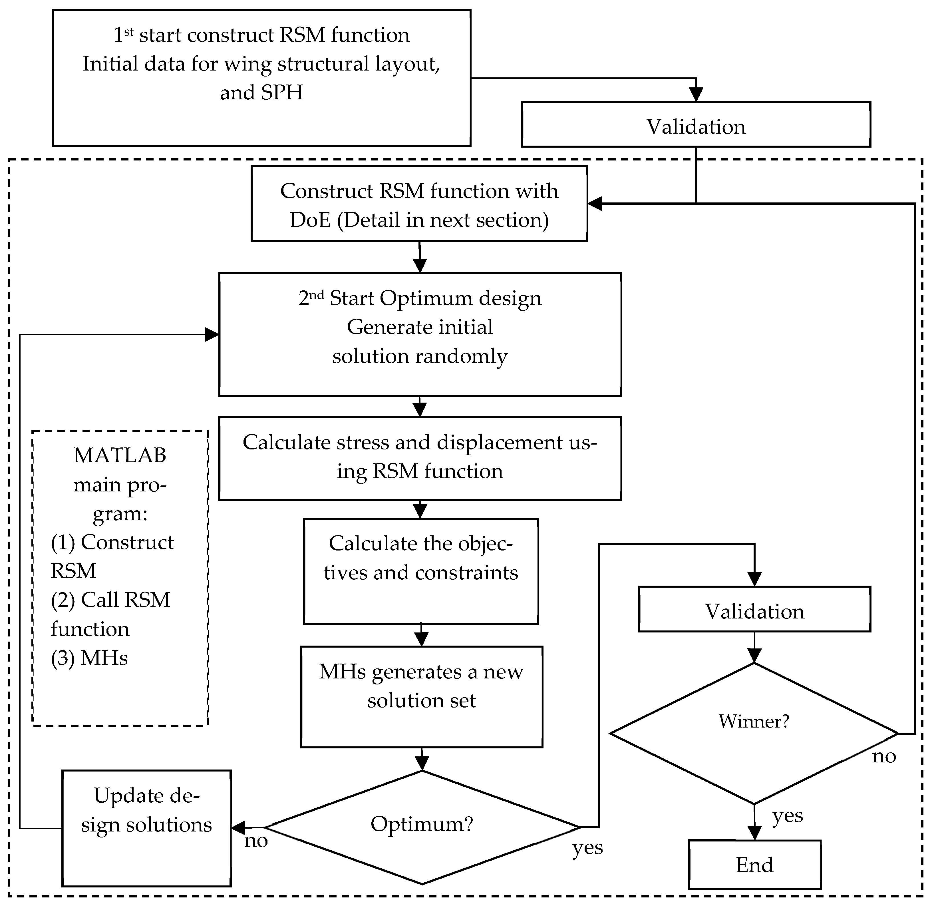
2. Methodologies
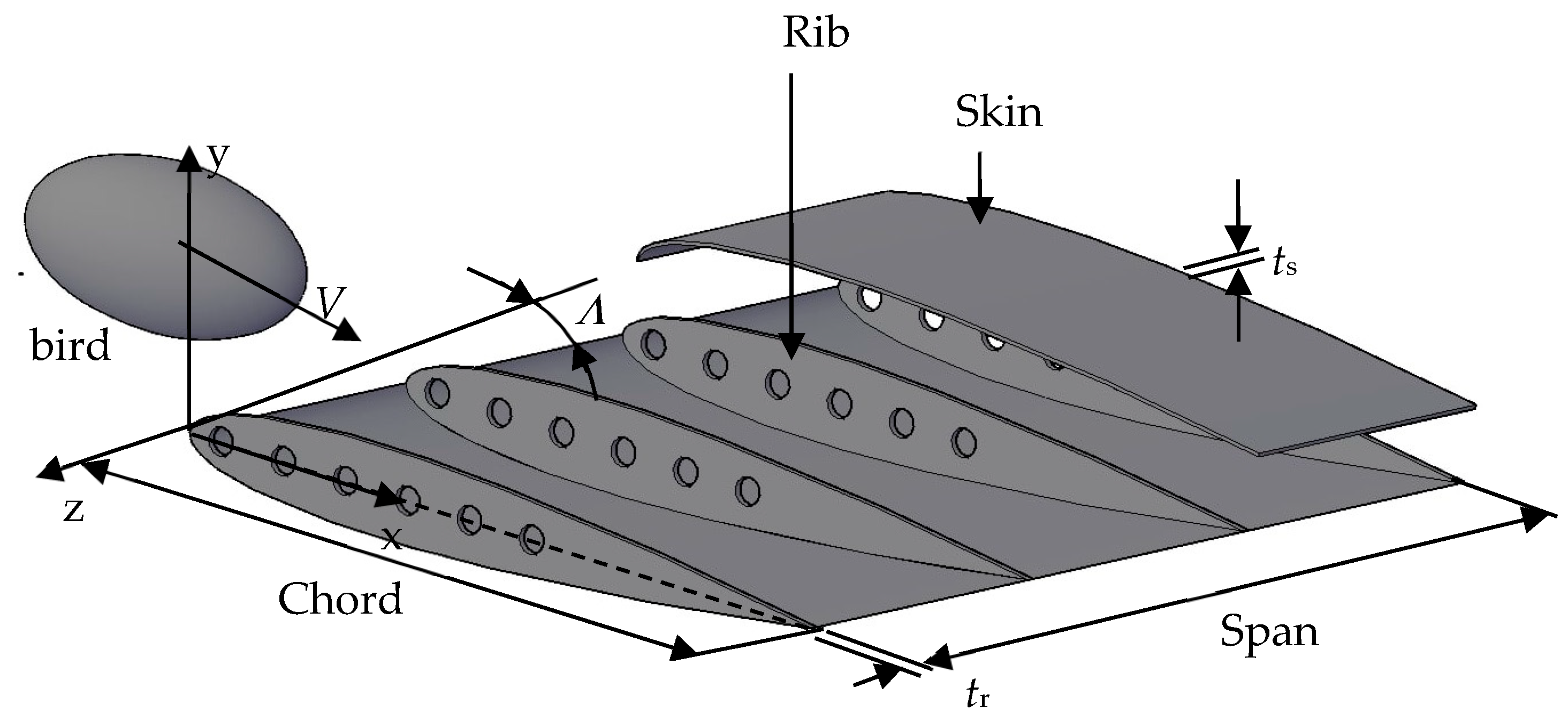
2.1. Aircraft Wing Structure Model and Bird Parameters
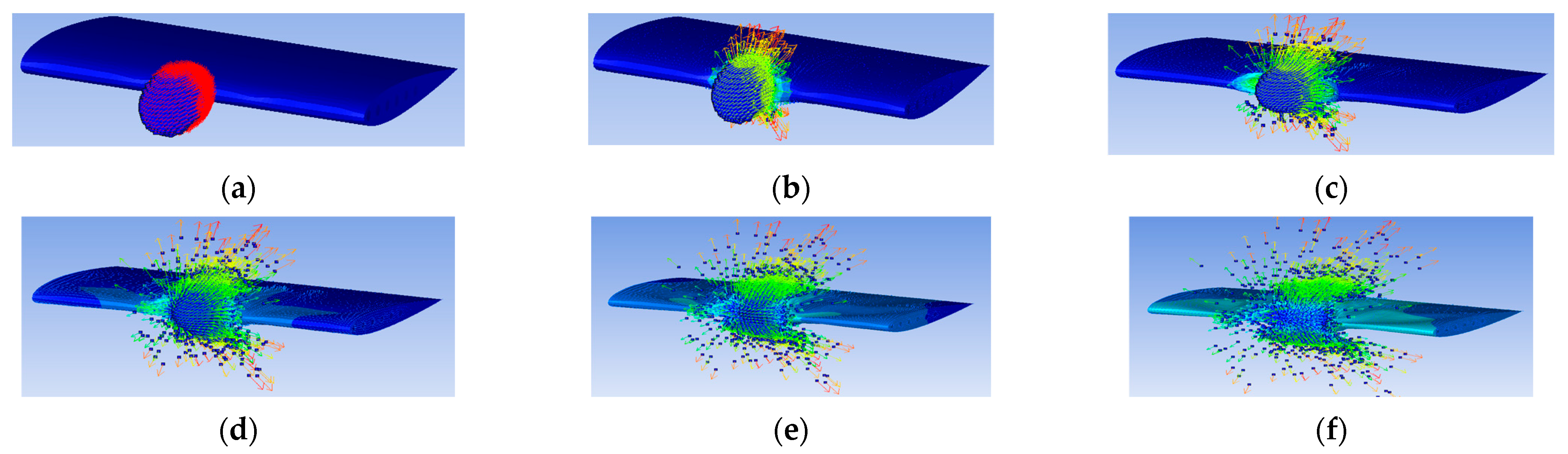
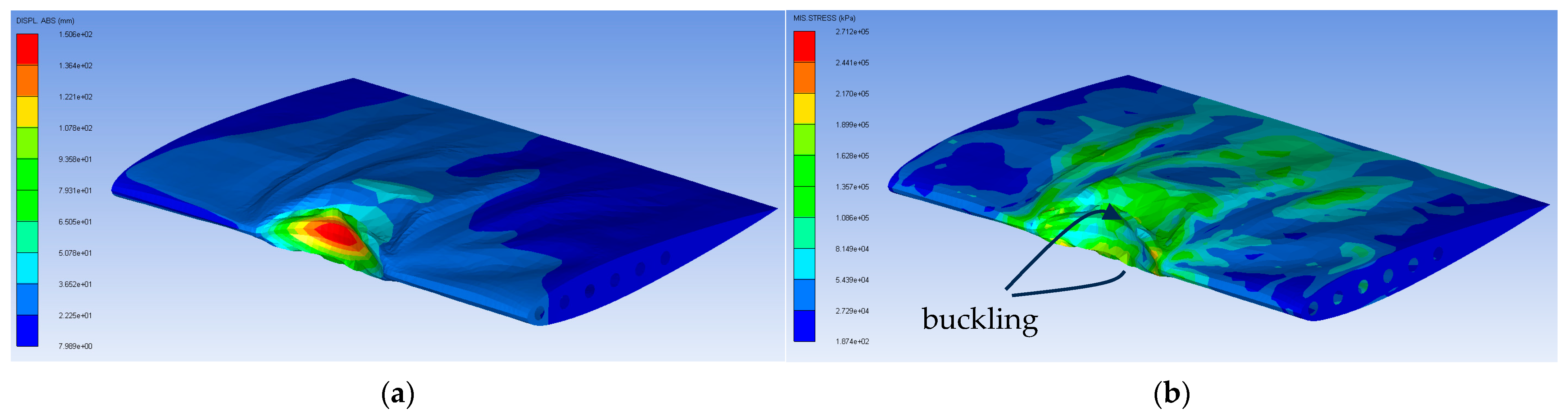
2.2. SPH and Validation of Wing Model
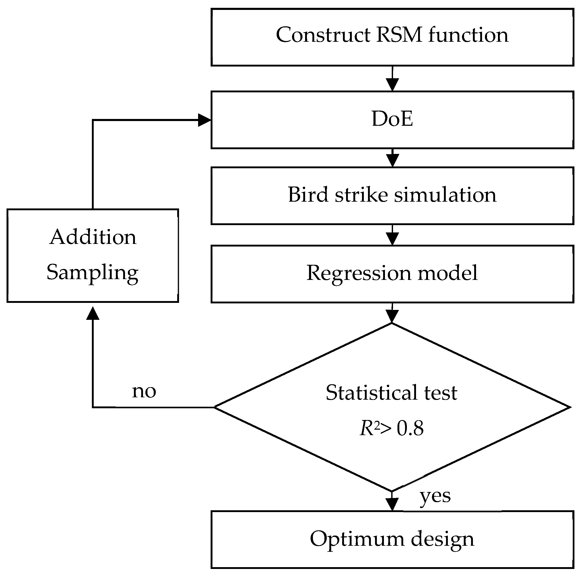
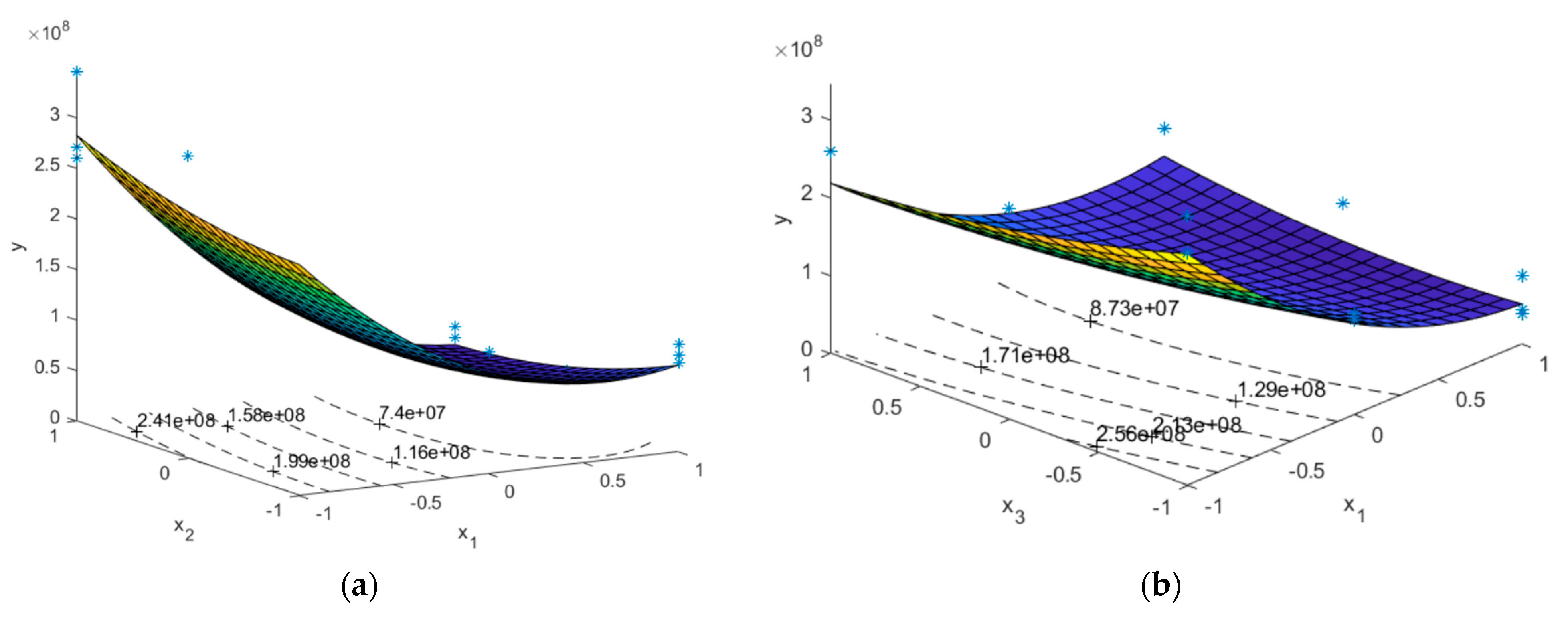
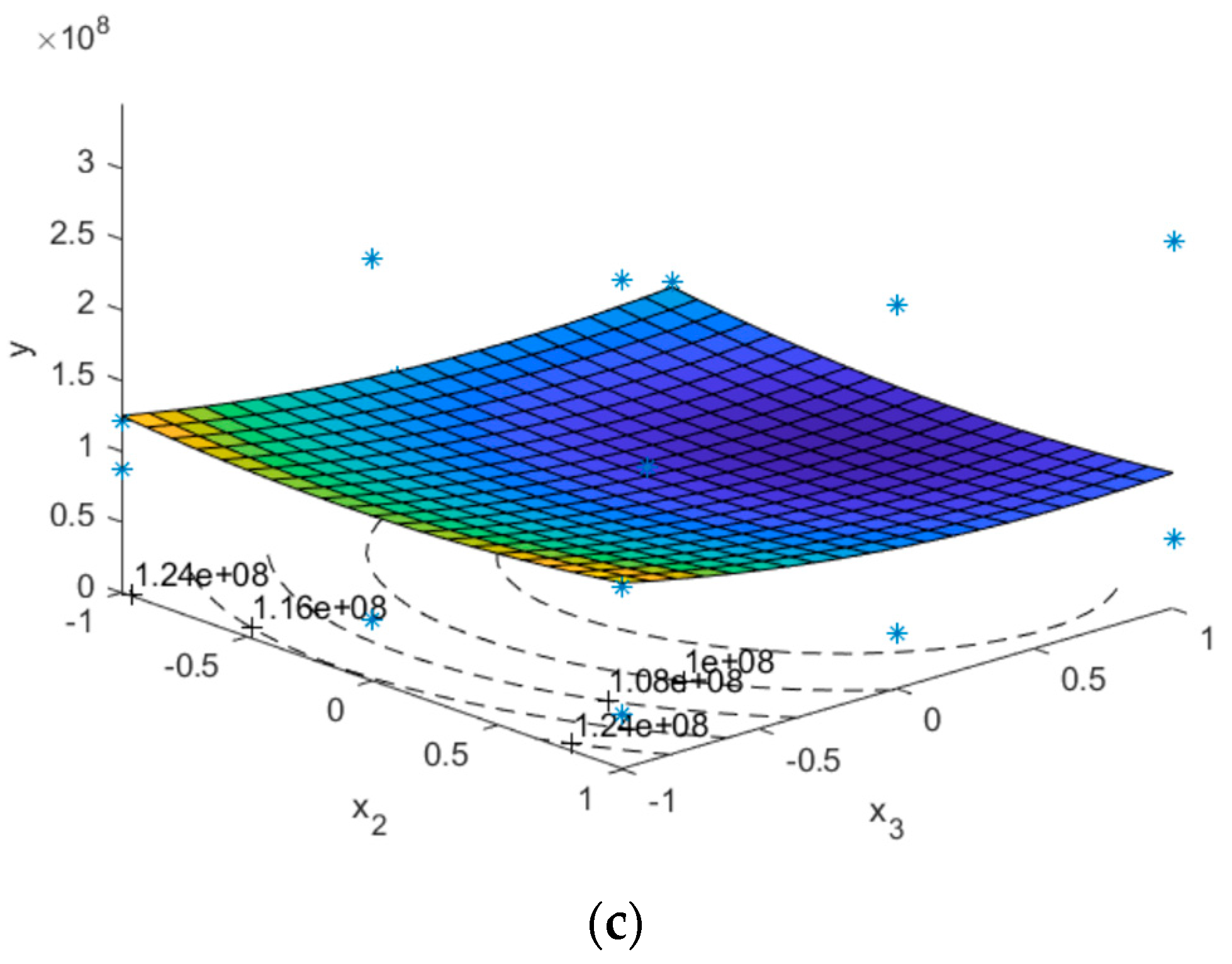
2.3. Response Surface Method
2.3.1. Regression Model
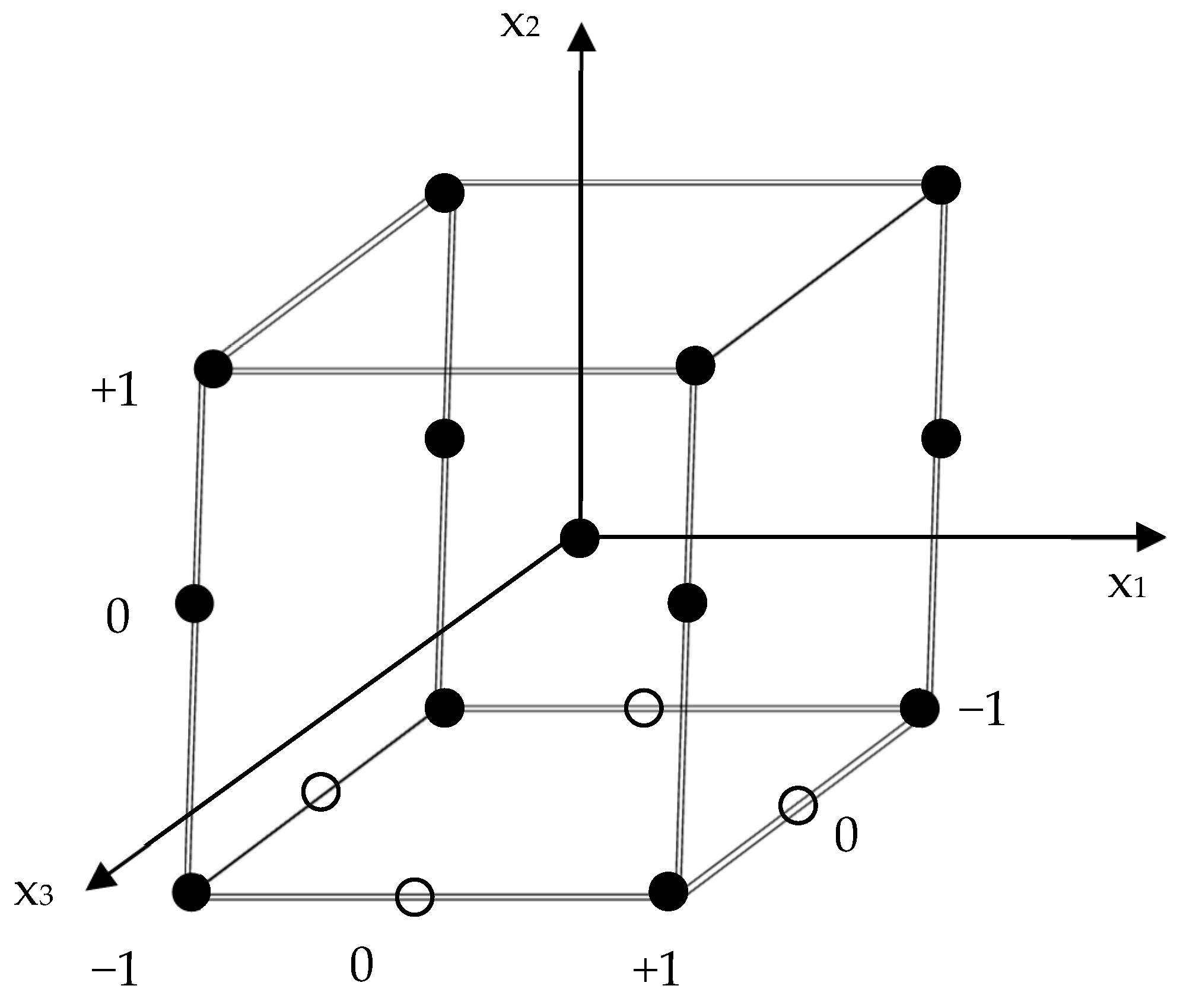
2.3.2. Design of Experiment
2.3.3. Statistical Analysis
2.4. Optimization Problem
2.4.1. Optimization Design Problem
2.4.2. Metaheuristics
3. Experimental Design
- (1)
- Teaching–learning-based optimization (TLBO): Parameter settings are not required.
- (2)
- Adaptive differential evolution with optional external archive (JADE): The parameters are self-adapted during an optimization process.
- (3)
- Population-based incremental learning (PBIL). The learning rate, mutation shift, and mutation rate are set at 0.5, 0.7, and 0.2, respectively.
4. Design Results and Discussions
5. Conclusions
Author Contributions
Funding
Data Availability Statement
Acknowledgments
Conflicts of Interest
References
- Matos, N.; Gomes, M.; Infante, V. Numerical modelling of soft body impacts: A review. Eng. Fail. Anal. 2023, 153, 107595. [Google Scholar] [CrossRef]
- Dede, O.; Kayran, A. Investigation of Effects of Bird Strike on Wing Leading Edge by Using Explicit Finite Element Method. In Proceedings of the 8th Ankara International Aerospace Conference-AIAC, Ankara, Turkey, 10–12 September 2015. [Google Scholar]
- Hedayati, R.; Ziaei-Rad, S. Effect of bird geometry and orientation on bird-target impact analysis using SPH method. Int. J. Crashworthiness 2012, 17, 445–459. [Google Scholar] [CrossRef]
- Guida, M.; Marulo, F.; Belkhelfa, F.Z.; Russo, P. A review of the bird impact process and validation of the SPH impact model for aircraft structures. Prog. Aerosp. Sci. 2022, 129, 100787. [Google Scholar] [CrossRef]
- Lavoie, M.A.; Gakwaya, A.; Nejad Ensan, M.; Zimcik, D.G. Validation of available approaches for numerical bird strike modeling tools. Int. Rev. Mech. Eng. 2007, 1, 380–389. [Google Scholar]
- Zhou, Y.; Sun, Y.; Huang, T. Bird-Strike Resistance of Composite Laminates with Different Materials. Materials 2020, 13, 129. [Google Scholar] [CrossRef] [PubMed]
- Yu, Z.; Xue, P.; Yao, P.; Zahran, M.S. Novel Design of Wing Leading Edge Against Birdstrike. J. Aerosp. Eng. 2020, 33, 04020018. [Google Scholar] [CrossRef]
- Tezel, M.C.; Yamaner, Y.; Çoğuz, B.A.; Acar, E. Exploring Design Options for Wing Leading Edge Against Bird Strike. J. Aircr. 2022, 60, 66–79. [Google Scholar] [CrossRef]
- Dong, Y.; Hussain, I.; He, S. Structural topology optimization of aircraft wing leading edge fabricated of multilayer composites. Aerosp. Sci. Technol. 2025, 159, 109993. [Google Scholar] [CrossRef]
- Aslam, M.A.; Rayhan, S.B.; Zhang, K. Dynamic Response of Structurally Reinforced Wing Leading Edge against Soft Impact. Aerospace 2022, 9, 260. [Google Scholar] [CrossRef]
- Guida, M.; Marulo, F.; Meo, M.; Riccio, M. Analysis of Bird Impact on a Composite Tailplane Leading Edge. Appl. Compos. Mater. 2008, 15, 241–257. [Google Scholar] [CrossRef]
- Hedayati, R.; Ziaei-Rad, S. A new bird model and the effect of bird geometry in impacts from various orientations. Aerosp. Sci. Technol. 2013, 28, 9–20. [Google Scholar] [CrossRef]
- Liu, J.; Zhang, C.Y.; Juan, B.P.; Li, Z.H.; Zhang, C.; Li, Y.L. Damage sensitivity of a wing-type leading edge structure impacted by a bird. Chin. J. Aeronaut. 2023, 36, 328–343. [Google Scholar] [CrossRef]
- Myers, R.H.; Montgomery, D.C. Response Surface Methodology: Process and Product Optimization Using Designed Experiments, 2nd ed.; Wiley: New York, NY, USA, 2002. [Google Scholar]
- Leyva-Jiménez, F.-J.; Fernández-Ochoa, Á.; Cádiz-Gurrea, M.d.l.L.; Lozano-Sánchez, J.; Oliver-Simancas, R.; Alañón, M.E.; Castangia, I.; Segura-Carretero, A.; Arráez-Román, D. Application of Response Surface Methodologies to Optimize High-Added Value Products Developments: Cosmetic Formulations as an Example. Antioxidants 2022, 11, 1552. [Google Scholar] [CrossRef] [PubMed]
- Kumkam, N.; Suratemeekul, N.; Sleesongsom, S. A New Conceptual Design of Twisting Morphing Wing. Biomimetics 2025, 10, 110. [Google Scholar] [CrossRef] [PubMed]
- Phromphan, P.; Suvisuthikasame, J.; Kaewmongkol, M.; Chanpichitwanich, W.; Sleesongsom, S. A New Latin Hypercube Sampling with Maximum Diversity Factor for Reliability-Based Design Optimization of HLM. Symmetry 2024, 16, 16–901. [Google Scholar] [CrossRef]
- ASTM. Standard Test Method for Bird Impact Testing of Aerospace Transparent Enclosures. Available online: https://www.astm.org/f0330-21.html (accessed on 22 March 2025).
- Hedayati, R.; Sadighi, M. Bird Strike: An Experimental, Theoretical and Numerical Investigation; Woodhead Publishing: Cambridge, UK, 2015. [Google Scholar]
- Goyal, V.; Huertas, C.; Leutwiler, T.; Borrero, J.; Vasko, T. Robust Bird-Strike Modeling Based on SPH Formulation Using LS DYNA. In Proceedings of the 47th AIAA/ASME/ASCE/AHS/ASC Structures, Structural Dynamics, and Materials Conference, Newport, RI, USA, 1–4 May 2006; Volume 3, pp. 2044–2061. [Google Scholar]
- Hedayati, R.; Sadighi, M. Effect of Using an Inner Plate Between Two Faces of a Sandwich Structure in Resistance to Bird-Strike Impact. J. Aerosp. Eng. 2016, 29, 04015020. [Google Scholar] [CrossRef]
- Sleesongsom, S.; Bureerat, S. Four-bar linkage path generation through self-adaptive population size teaching-learning based optimization. Knowl.-Based Syst. 2017, 135, 180–191. [Google Scholar] [CrossRef]
- Bureerat, S. Improved Population-Based Incremental Learning in Continuous Spaces. In Soft Computing in Industrial Applications; Gaspar-Cunha, A., Takahashi, R., Schaefer, G., Costa, L., Eds.; Advances in Intelligent and Soft Computing; Springer: Berlin/Heidelberg, Germany, 2011; Volume 96, pp. 77–86. [Google Scholar]


| No. | Parameters | Values/Shape |
|---|---|---|
| 1 | A section-span length, L(mm) | 1500 |
| 2 | Root chord length, RC (mm) | 1000 |
| 3 | Tip chord length, TC (mm) | 1000 |
| 4 | Sweep angle Λ, (degree) | 0–40° |
| 5 | Number of ribs | 4 |
| 6 | NACA | 0012 |
| 7 | Number of skin | 1 |
| 8 | Skin thickness (ts) (mm) | 0.5–2 |
| 9 | Ribs thickness (tr) (mm) | 0.5–5 |
| 10 | Aircraft speed (m/s) | 100 |
| 11 | Bird shape | ellipsoid |
| Aluminum (AL5083H116) Properties | Value | Unit |
|---|---|---|
| Young’s modulus (E) | 70 × 109 | Pa |
| Yield stress (σy) | 167 × 106 | Pa |
| Poisson’s ratio (ν) | 0.3 | - |
| Density (ρ) | 2700 | kg/m3 |
| Bird (Water 2) Properties | Value | Unit |
| Mass | 1.81 | kg |
| Poisson’s ratio (ν) | - | - |
| Density (ρ) | 1000 | kg/m3 |
| Run | x1 = ts (mm) | x2 = tr (mm) | x3 = Λ (degree) | y1 (mm) | y2 (MPa) |
|---|---|---|---|---|---|
| 1 | 0.5 | 5.0 | 40 | 98.35 | 259.6 |
| 2 | 2.0 | 0.5 | 40 | 5.33 | 106.8 |
| 3 | 2.0 | 5.0 | 40 | 5.325 | 49.51 |
| 4 | 0.5 | 5.0 | 40 | 98.35 | 259.6 |
| 5 | 0.5 | 5.0 | 20 | 150.6 | 271.2 |
| 6 | 2.0 | 0.5 | 20 | 6.453 | 95.58 |
| 7 | 2.0 | 5.0 | 20 | 5.315 | 39.41 |
| 8 | 0.5 | 5.0 | 20 | 150.6 | 271.2 |
| 9 | 0.5 | 5.0 | 0 | 170 | 345.9 |
| 10 | 2.0 | 0.5 | 0 | 6.485 | 87.79 |
| 11 | 2.0 | 5.0 | 0 | 5.417 | 39.33 |
| 12 | 0.5 | 5.0 | 0 | 170 | 345.9 |
| 13 | 1.25 | 2.75 | 20 | 10.18 | 94.62 |
| Run | x1 = ts (mm) | x2 = tr (mm) | x3 = Λ (degree) | y1 (mm) | y2 (MPa) |
|---|---|---|---|---|---|
| 14 | 1.25 | 0.5 | 0 | 14.52 | 120.9 |
| 15 | 2.0 | 2.75 | 0 | 5.917 | 43.93 |
| 16 | 0.5 | 2.75 | 0 | 177.4 | 298.6 |
| 17 | 1.25 | 5.0 | 0 | 11.63 | 129.7 |
| Run | y1 (mm) | Results | y2 (MPa) | Results |
|---|---|---|---|---|
| 1 | 98.35 | 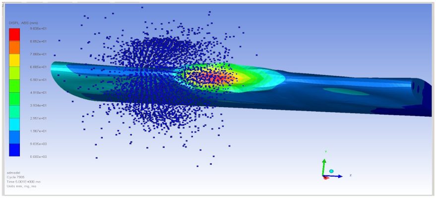 | 259.6 | 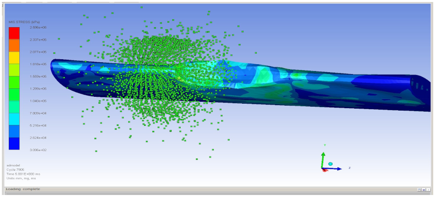 |
| 2 | 5.33 | 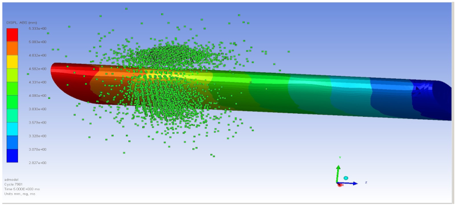 | 106.8 | 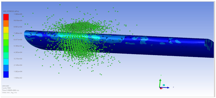 |
| 3 | 5.325 |  | 49.51 | 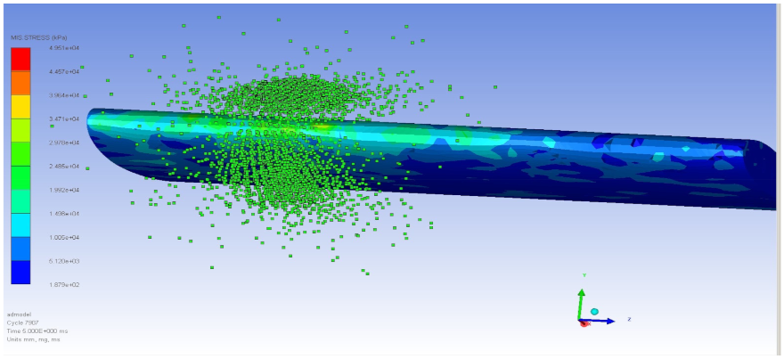 |
| 4 | 98.35 | 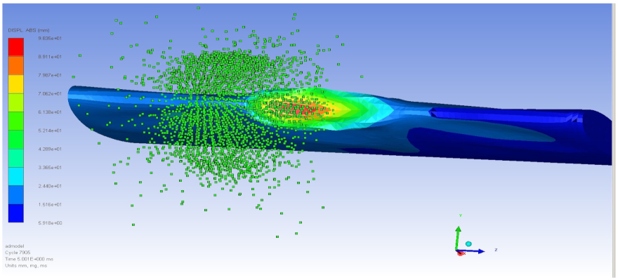 | 259.6 |  |
| 5 | 150.6 | 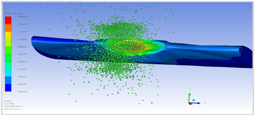 | 271.2 |  |
| 6 | 6.453 | 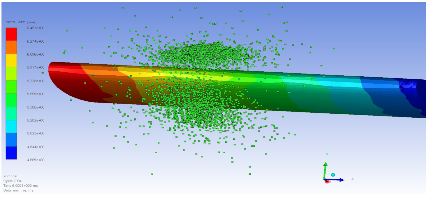 | 95.58 |  |
| 7 | 5.315 |  | 39.41 |  |
| 8 | 150.6 |  | 271.2 |  |
| 9 | 170 |  | 345.9 | 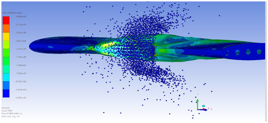 |
| 10 | 6.485 |  | 87.79 | 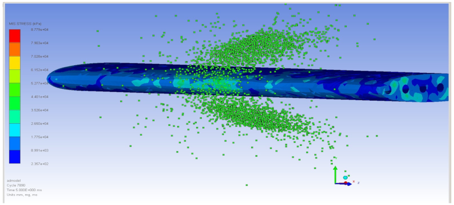 |
| 11 | 5.417 | 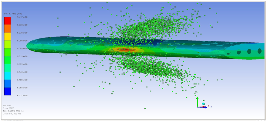 | 39.33 | 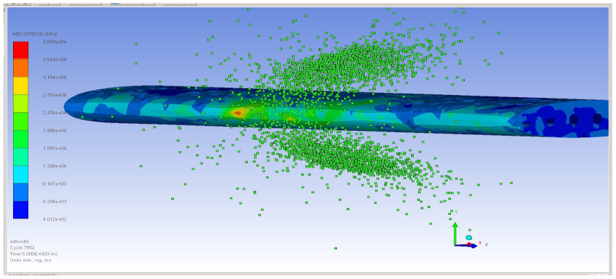 |
| 12 | 170 |  | 345.9 |  |
| 13 | 10.18 |  | 94.62 |  |
| Run | TLBO | JADE | PBIL | Actual |
|---|---|---|---|---|
| ts (mm) | 1.8 | 1.7 | 1.8 | 1.8 |
| tr (mm) | 2.0 | 2.0 | 2.0 | 2.0 |
| Λ (degree) | 16.439 | 18.456 | 17.610 | 17.610 |
| Max VMS (MPa) | 54.775 | 59.334 | 54.177 | 39.09 |
| Disp. (mm) | −0.3343 | −4.5968 | −0.4595 | 6.669 |
| Mean | 59.483 | 60.372 | 56.562 | |
| Min | 54.775 | 55.934 | 54.177 | |
| Max | 64.921 | 66.694 | 61.178 | |
| Std | 3.692 | 3.488 | 2.115 |
Disclaimer/Publisher’s Note: The statements, opinions and data contained in all publications are solely those of the individual author(s) and contributor(s) and not of MDPI and/or the editor(s). MDPI and/or the editor(s) disclaim responsibility for any injury to people or property resulting from any ideas, methods, instructions or products referred to in the content. |
© 2025 by the authors. Licensee MDPI, Basel, Switzerland. This article is an open access article distributed under the terms and conditions of the Creative Commons Attribution (CC BY) license (https://creativecommons.org/licenses/by/4.0/).
Share and Cite
Timhede, V.; Timhede, S.; Winyangkul, S.; Sleesongsom, S. Aircraft Wing Design Against Bird Strike Using Metaheuristics. Aerospace 2025, 12, 436. https://doi.org/10.3390/aerospace12050436
Timhede V, Timhede S, Winyangkul S, Sleesongsom S. Aircraft Wing Design Against Bird Strike Using Metaheuristics. Aerospace. 2025; 12(5):436. https://doi.org/10.3390/aerospace12050436
Chicago/Turabian StyleTimhede, Vanessa, Silvia Timhede, Seksan Winyangkul, and Suwin Sleesongsom. 2025. "Aircraft Wing Design Against Bird Strike Using Metaheuristics" Aerospace 12, no. 5: 436. https://doi.org/10.3390/aerospace12050436
APA StyleTimhede, V., Timhede, S., Winyangkul, S., & Sleesongsom, S. (2025). Aircraft Wing Design Against Bird Strike Using Metaheuristics. Aerospace, 12(5), 436. https://doi.org/10.3390/aerospace12050436