Article

Experimental and Numerical Study on Flow and Heat Transfer Characteristics of Additively Manufactured Triply Periodic Minimal Surface (TPMS) Heat Exchangers for Micro Gas Turbine

1
Institute of Turbomachinery, School of Mechanical Engineering, Shanghai Jiao Tong University, Shanghai 200240, China
2
Shenzhen Research Institute, Shanghai Jiao Tong University, Shenzhen 518000, China
*
Author to whom correspondence should be addressed.
Aerospace 2025, 12(5), 416; https://doi.org/10.3390/aerospace12050416
Submission received: 25 March 2025 / Revised: 23 April 2025 / Accepted: 29 April 2025 / Published: 7 May 2025
(This article belongs to the Section Aeronautics)

Abstract

:
This paper proposes two compact, efficient, and lightweight heat exchangers based on triply periodic minimal surfaces (TPMSs). Designed in an annular configuration, the heat exchangers meet the requirements of micro gas turbines for compactness. Two prototypes of Diamond and Gyroid modular TPMS heat exchangers were fabricated using selective laser melting (SLM) with stainless steel. The flow and heat transfer experimental results indicate that, within a Reynolds number range of 200 to 800, the effectiveness of both heat exchangers remained above 0.62, and the average Nusselt numbers of the Diamond and Gyroid structures reached 3.60 and 4.06 times that of the printed circuit heat exchanger (PCHE), respectively. Although both heat exchangers exhibited relatively high friction factors, their overall performance surpassed that of conventional heat exchangers. Additionally, performance comparisons with existing TPMS heat exchangers revealed that smaller lattice sizes contribute to improved volume-based power density, although they result in increased pressure loss. Simulation results indicated that the “merge–split” effect present in both structures enhances heat transfer between the fluid and the wall. Furthermore, the complex channels of the TPMS structures ensure that the fluid maintains strong turbulence intensity throughout the heat exchanger. This study demonstrates that stainless steel TPMS structures can serve as excellent candidates for applications in micro gas turbines.

1. Introduction

The rapid advancements in energy technologies are driving modern power devices toward higher levels of compactness and integration. This development involves high levels of power consumption and hence requires high-performance cooling technologies. Heat exchangers play a critical role in various industrial fields, such as chemical engineering [1], aerospace [2], and nuclear energy [3]. Heat exchangers enable the recovery of waste heat and further improve thermal effectiveness. In the field of micro gas turbines, adding a heat exchanger (recuperator) between the compressor and the turbine can potentially increase the overall thermal efficiency of the system from 15–20% to 30% or even higher. Given the compact size of micro gas turbines, to ensure their compactness, heat exchangers are predominantly designed in a circular configuration [4].
Conventional heat exchangers employed in micro gas turbines are predominantly of the plate–fin and primary surface types; studies have also been conducted to modify their internal structures to enhance their thermal performances [5]. However, conventional designs are still impeded by their large size and heavy weight. In addition, these heat exchangers have areas with low specific heat transfer. Furthermore, constrained by manufacturing techniques, conventional fabrication methods are incapable of producing complex structures, which significantly limit innovation and design possibilities for heat exchangers. Highly complex structures with large surface areas are required to improve the compactness and thermal effectiveness of heat exchangers.
The development of additive manufacturing (AM) technologies has significantly expanded the design possibilities for compact heat exchangers. AM, commonly known as 3D printing, is a transformative manufacturing process that builds objects layer by layer from digital models, enabling the creation of complex geometries that are difficult to achieve with conventional methods. AM has made it possible to fabricate porous media with customized topological structures, particularly those inspired by nature, such as triply periodic minimal surfaces (TPMSs), which have garnered significant attention due to their superior thermal–mechanical performances [6]. TPMS structures were first discovered in the 19th century by Schwarz [7]. These structures, characterized by an overall mean curvature of zero, exhibit periodicity in three-dimensional space with smooth and continuous surfaces [8]. TPMSs can be classified into two types: solid (skeletal) networks and sheet networks [9,10]. The sheet-based TPMS structures are particularly notable for their ability to partition three-dimensional space into two non-interconnected channels, which can independently accommodate cold and hot fluids, making these structures suitable for two-fluid heat exchanger designs. AM technologies have been used to fabricate TPMS structures for various fields, such as mechanical components, heat sinks, heat exchangers, and fluid mixers [11,12,13]. The mechanical performance of sheet-based TPMSs also outperforms various lattice designs, which further confirms the usability of the heat exchanger application [14].
The flow and heat transfer performance of different TPMS topologies have been intensively investigated to find the optimal model, with various studies showing that the TPMS heat exchangers provide better heat transfer performances than conventional designs. Femmer et al. [15] investigated the performance of heat exchangers based on Diamond, Gyroid, Primitive, and I-WP TPMS structures and compared them with conventional flat-plate and hollow-tube structures. The results showed that the performance of TPMS heat exchangers exceeded those of hollow-tube and flat-plate designs by an order of magnitude, demonstrating superior heat transfer characteristics. Among these, the Diamond structure exhibited the best heat transfer performance under its inherent pressure loss. Reynolds et al. [16] manufactured a series of TPMS heat exchangers and found that the Nusselt numbersof Gyroid heat exchangers is 112% higher than that of straight tubes, while their friction factor is the lowest among various TPMS structures. Yan et al. [17] conducted simulations of five Lattice structures; they demonstrated that, within the Reynolds number range of 200–500, the overall heat transfer performances of the Gyroid, Diamond, and I-WP structures improved by 90% compared to printed circuit heat exchanger (PCHE). Huang et al. [18] investigated the thermal–hydraulic performance of Diamond, Fischer–Koch S, and PCHE through numerical simulations. The TPMS heat exchanger demonstrated a fourfold increase in power-to-weight ratio while reducing the volume by half compared to PCHE, highlighting the significant potential of TPMS heat exchangers for further space and weight savings in aerospace applications. Wang et al. [19] addressed the demand for highly efficient heat exchangers in advanced nuclear systems by designing two types of heat exchangers based on I-WP and Primitive structures; the numerical simulation results indicated that the TPMS heat exchangers achieved a total heat transfer rate approximately 2–3 times higher than that of PCHE while reducing the volume by half.
The configurations of the TPMS structures, such as porosity, unit cell size, and even material, have shown a significant influence on heat transfer effectiveness. Mahmoud et al. [20] fabricated four heat exchanger prototypes based on Gyroid structures by controlling lattice thickness and porosity. The study revealed that thinner lattice structures and stretched TPMS channels help reduce pressure loss. However, it also pointed out that lattice thicknesses below 0.2 mm should be avoided during 3D printing to prevent leakage. Cheng et al. [21] examined the correlations between flow resistance and heat transfer coefficients for four TPMS structures within the Reynolds number range of 10–129 and porosity range of 0.2–0.8. The results showed that the I-WP structure achieved the highest heat transfer performance per unit flow resistance, which was 1.9 times that of the Diamond structure. Tang et al. [22] observed that the superior convective heat transfer performance of the Diamond structure compared to other TPMS structures is due to its lack of “through-holes” in its geometry, which increases fluid disturbances. Liang et al. [23] fabricated three types of heat exchangers: Diamond, Gyroid, and Primitive. The experimental results demonstrated that the Diamond structure exhibited a higher heat transfer rate compared to the Gyroid and Primitive structures. It was observed that the surface area-to-volume ratio of TPMS units increases exponentially as the unit size decreases, suggesting potential improvements in compactness and thermal performance. Liang et al. [24] designed three cross-flow Diamond heat exchangers with different unit sizes but identical porosity. Experimental results revealed that smaller unit sizes tend to induce large-scale bifurcation flow, thereby enhancing heat transfer effectiveness, albeit at the cost of increased pressure loss. Similarly, Gao et al. [25] found that smaller lattice sizes lead to more uniform temperature distributions and higher effectiveness but also result in greater pressure loss.
The flow and heat transfer performance of different TPMS heat exchanger materials have also been studied. Gao et al. [26] fabricated two Diamond heat exchangers with identical structures using pure copper and 316 L stainless steel, respectively. Experimental results showed that the convective heat transfer coefficient of the pure copper TPMS heat exchanger was approximately 1.17–1.33 times higher than that of the 316 L stainless steel counterpart, indicating that pure copper is a promising candidate material for next-generation heat exchangers. Qian et al. [27] fabricated three pure copper heat exchangers based on Primitive, Gyroid, and Fischer–Koch S structures. Their findings also confirmed that the copper heat exchangers exhibited higher volumetric heat transfer rates. Among these, the Fischer–Koch S structure demonstrated significantly superior heat transfer performance compared to the other two. However, its complex internal channels, which continuously alter the flow direction, resulted in poorer temperature uniformity and significantly higher pressure losses than those of the Gyroid structure [28].
Although there has been extensive research on TPMS heat exchangers, most studies have primarily focused on investigating the flow and heat transfer characteristics of a few representative TPMS structures, such as 4 × 4 × 4 or 1 × 1 × n. However, these dimensions are far from meeting the size requirements necessary for industrial heat exchangers. Moreover, these studies often employ large lattice sizes, which result in lower compactness and fail to fully utilize the inherent high compactness of TPMS structures.
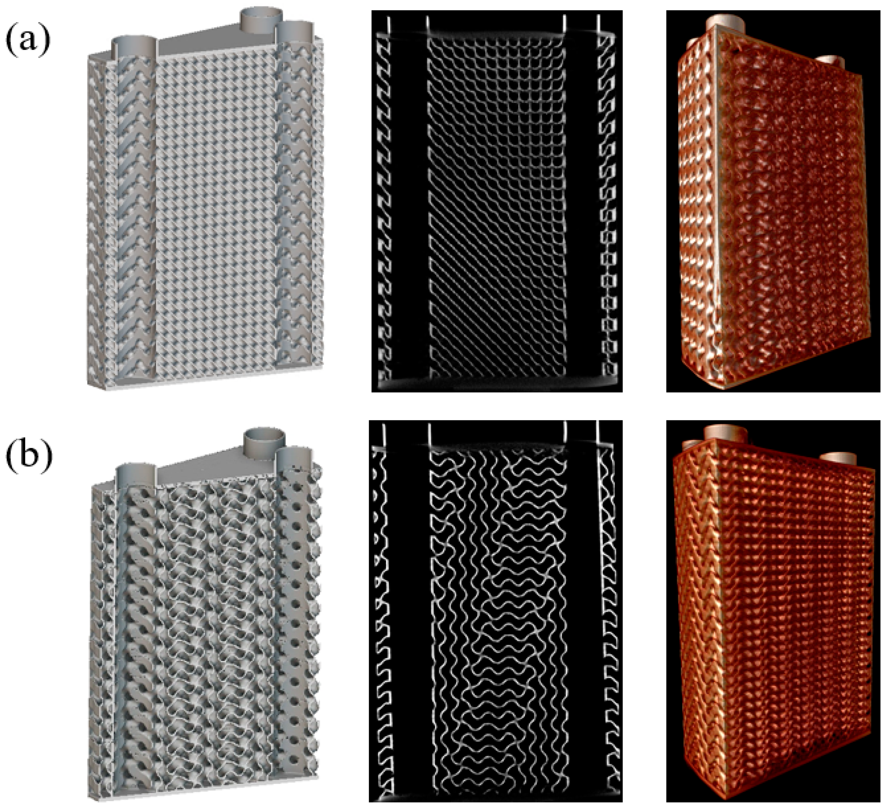
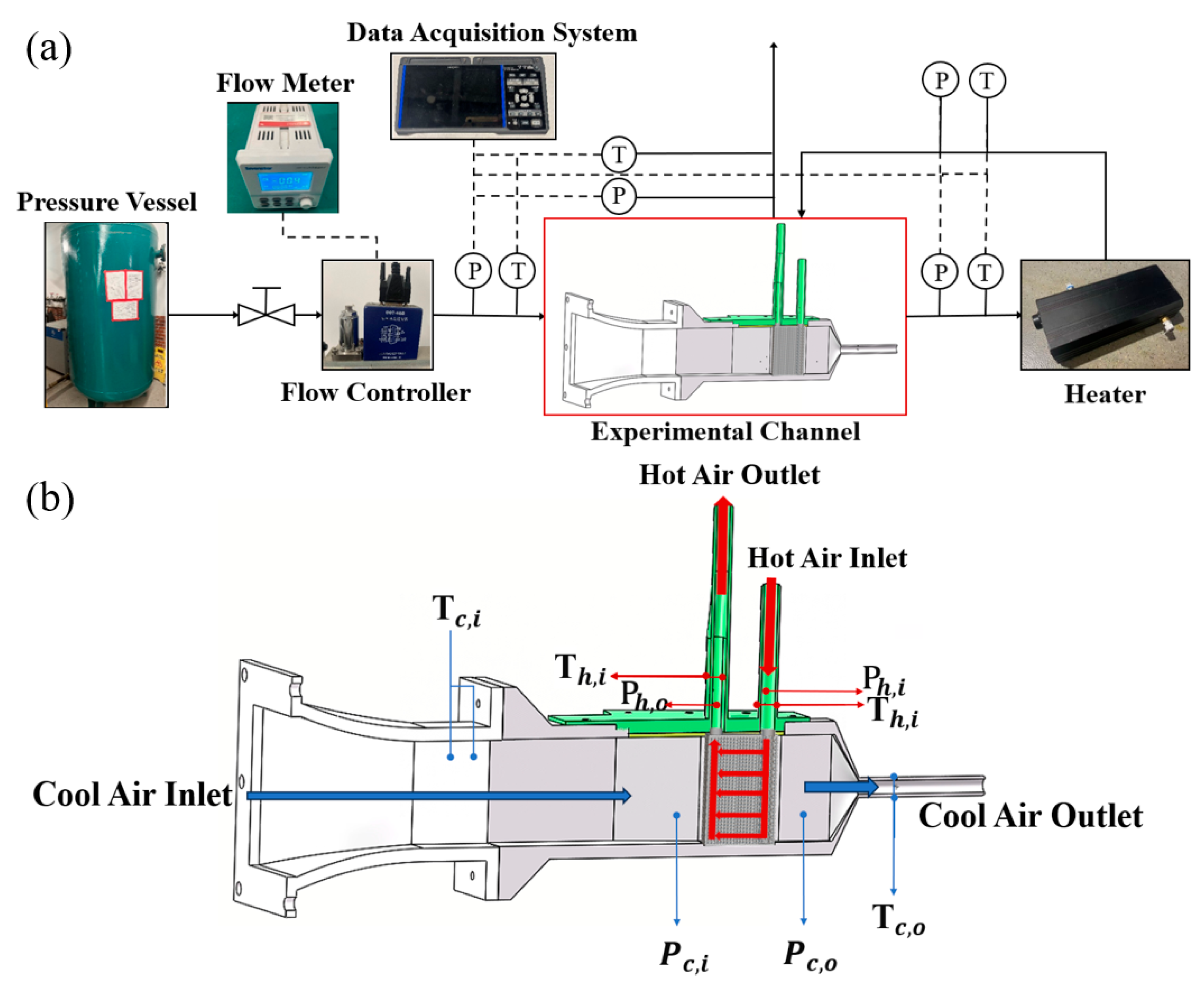
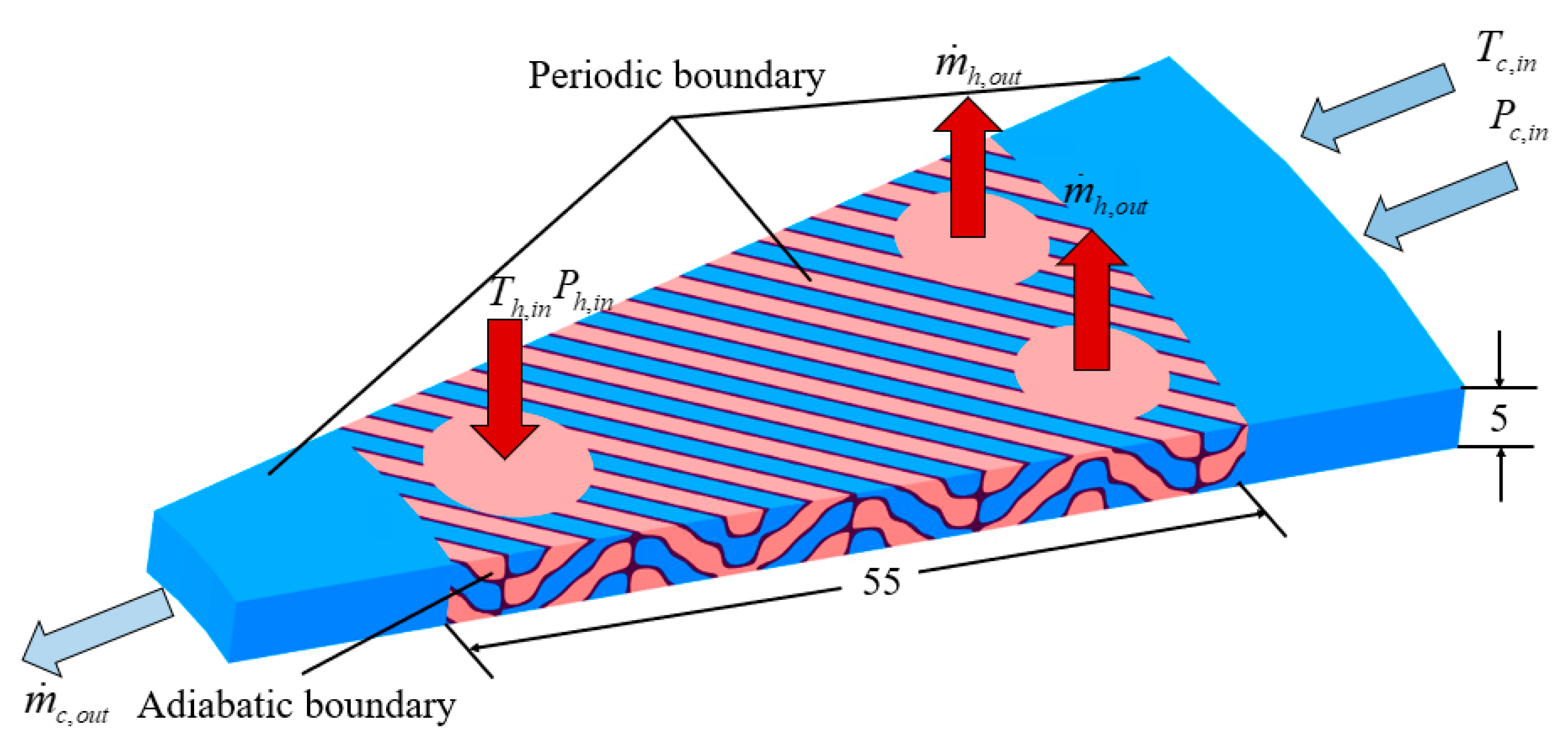
In this study, to address the demand for highly efficient and compact heat exchangers in micro gas turbines, an annular TPMS-based heat exchanger is proposed, leveraging additive manufacturing technology. This design can be directly installed on the outer side of the combustion chamber, significantly reducing the required installation space. Two modular prototypes of the annular heat exchangers were fabricated, which comprise a large number of lattice units with smaller lattice sizes, aligning with the requirements for industrial compact heat exchangers. The heat transfer performance of the heat exchangers was investigated through steady-state experiments, and their performance was compared with those of existing heat exchangers and other TPMS designs. Additionally, numerical simulations of the TPMS heat exchanger were conducted to further elucidate the mechanisms of heat transfer enhancement. This study aims to address the lack of data on the flow and heat transfer performance of compact heat exchangers with large-scale lattices.

2. Methodology

2.1. Physical Models and Characterization

2.1.1. Model Design

In previous studies, structures such as Diamond, Gyroid, IWP, Primitive, and Fischer–Koch S have been widely applied in triply periodic minimal surface (TPMS) heat exchangers. Structures such as Diamond, Gyroid, and Fischer–Koch S possess relatively high specific surface areas, which allow them to offer significantly larger heat transfer areas compared to other TPMS surfaces in compact spaces. Additionally, the intricate flow channels within TPMS surfaces contribute to disrupting the flow boundary layer, reducing thermal resistance, and further enhancing heat transfer. On the other hand, surfaces like IWP and Primitive feature simpler structures, which are more effective in minimizing pressure losses. However, previous studies [15,22,29] suggest that IWP and Primitive structures demonstrate inferior heat transfer performance, as their specific surface areas are significantly lower than those of other TPMS designs. Meanwhile, Fischer–Koch S, due to its excessively complex channels, demonstrates extremely high pressure losses [28]. Considering the trade-offs between the advantages and disadvantages of these structures, this study selects two types of TPMS units, Diamond and Gyroid, as the unit models to investigate the flow and heat transfer performances of heat exchangers.
The surfaces of Diamond and Gyroid are defined by their corresponding implicit function equations, as shown in Table 1. In these equations, ω represents the periodicity of the TPMS structure along the x, y, and z directions, while C(x,y,z) represents the distance on which the TPMS surface is translated along the normal direction. By selecting two different C(x,y,z) values, the resulting two TPMS surfaces can be closed to create sheet-based TPMS structures with a defined thicknesses. These structures are set as solid domains. The sheet-based TPMS structures partition the space into two non-interconnected regions, which can serve as the hot and cold fluid domains, respectively. Smaller lattice sizes can significantly increase the specific surface area, but they also result in higher pressure losses per unit size and pose greater manufacturing challenges. Meanwhile, thinner walls help reduce solid thermal resistance and improve porosity, but they also increase the risk of leakage. This indicates that geometric parameters have significant impacts on the flow and heat transfer performances of TPMS structures. Considering both the high compactness and the risk of leakage, the design values for the TPMS unit size and porosity are set to 5 mm × 5 mm × 5 mm and 0.81, respectively. Figure 1a illustrates the basic unit of the heat exchanger designed using the Diamond structure as an example. The hot and cold fluids are separated by the Sheet–Diamond structure to prevent mixing between them. The entire annular heat exchanger design in a micro gas turbine with its flow directions is shown in Figure 1b. The heat exchanger adopts a modular manufacturing design concept in a micro gas turbine to reduce data transfer efficiency and ensure the accuracy of the AM process, which is arranged circumferentially with a periodic angle of 18°, an inner diameter of 95 mm, and an outer diameter of 205 mm. The heat exchanger includes 20 evenly distributed hot-side inlet manifolds and 40 hot-side outlet manifolds, and the 20 periodic unit models are combined using diffusion welding to form the complete annular heat exchanger. The model of each periodic heat exchanger unit and its cross-sectional view are shown in Figure 1c,d. During the heat exchange process, the hot fluid flows into the inner manifolds and exits through the outer manifolds. Meanwhile, the cold fluid flows radially, entering from the outer side and exiting at the inner side of the annular heat exchanger. The two fluid streams exchange heat in a counter-flow arrangement. Additionally, walls of a certain thickness are added at the inlets and outlets of both the hot and cold fluids to prevent the fluid streams from mixing within the heat exchanger. The specific geometric parameters of the heat exchanger are listed in Table 2.

2.1.2. Additive Manufacturing for Heat Exchanger Models

The TPMS heat exchangers are additively manufactured using the selective laser melting (SLM) technique. A layer-by-layer approach to the solidification and filling of the material in the SLM offers advantages such as high precision and excellent surface quality. By dividing the annular heat exchanger into 20 periodic unit models for independent fabrication, data transfer is significantly reduced with the high efficiency and accuracy of the additive manufacturing (AM) process. The metal material used for AM in this study is 316L stainless steel, as it provides both high thermal conductivity and low manufacturing costs compared to the material in the actual application, such as NI718. Two heat exchanger unit models based on the Diamond and Gyroid topologies are successfully fabricated. To evaluate the AM quality of two heat exchangers, high-resolution Computed Tomography (CT) scanning was executed at Shanghai Jiao Tong University, as shown in Figure 2. The cross-sectional CT scan images indicate that the wall of the TPMS heat exchanger exhibits no significant leakage, and the channels for the hot and cold fluids at the inlets and outlets are separated by walls of a certain thickness. This effectively prevents the mixing of the two fluid streams during the experimental process, thereby avoiding erroneous experimental results. By processing the slices obtained from CT scans, the average wall thicknesses and the porosities of the Diamond and Gyroid heat exchangers can be determined, as shown in Table 3. The average wall thicknesses of the Diamond and Gyroid heat exchangers are 0.284 mm and 0.355 mm, respectively; these values are 13.6% and 12.7% higher than the two design values. This discrepancy is primarily attributed to the following factors: (1) the presence of overlapping and fragmented facets in the Stereo lithography (STL) model, which leads to duplicated paths during the laser path generation process; (2) the adhesion of partially sintered powder to the underside of walls opposite to the printing direction during the scanning process. Additionally, the three-dimensional reconstruction models of the two heat exchangers demonstrate that the overall fabrication quality of the heat exchangers is satisfactory, indicating good manufacturing quality.
A confocal laser scanning microscope is also used to measure the roughness distribution on the internal surfaces of two heat exchangers, as shown in Figure 3. The images reveal slight undulations on the surface caused by residual metal powder particles. The average surface roughness values of the Diamond and Gyroid heat exchanger models are 5.122 μm and 9.617 μm, respectively. These values indicate that the machining traces of the heat exchanger structure are discernible, but within acceptable limits [25], demonstrating good surface quality for the additively manufactured TPMS heat exchangers.

2.2. Experimental Investigation

2.2.1. Experimental Setup and Measurement

The heat transfer performance of the TPMS heat exchangers is evaluated through steady-state experiments, and a schematic diagram of the experimental setup is shown in Figure 4a. The experimental apparatus consists of four main parts: the air supply system, the measurement system, the heating system, and the test section. The air supply system comprises an air storage tank, a flow controller, and a flow meter. The adjustable flow rate can reach a maximum of 2000 standard liters per minute. The measurement system includes a temperature measurement system and a pressure measurement system. The temperature measurement system consists of K-type thermocouples and a data logger. Two thermocouples are placed at both the inlet and outlet of the hot and cold fluid channels, and they are connected to the data logger. Meanwhile, the pressure measurement system includes four differential pressure sensors, with two sensors installed at the inlet and outlet of the hot and cold fluid channels, respectively, to measure the pressure loss across the heat exchanger. The heating system consists of an air heater with a maximum heating temperature of 100 °C and a rated power of 3 kW. The designed heating temperature for the steady-state experiments ranges from 50 °C to 90 °C, which falls within the operational range of the heater. The thermocouple arrangements, differential pressure gauge measurement points, and the internal fluid flow conditions within the experimental channel are shown in Figure 4b. All components of the test section are fabricated using nylon material, and the external surface is wrapped with thermal insulation cotton to ensure adiabatic boundary conditions. The details of the measured physical quantities and the corresponding experimental equipment used in the experiments are listed in Table 4. To ensure the accuracy of temperature and pressure data during the experiments, thermocouple calibration was performed within the experimental operating range. In this study, a thermostatic water bath was used to calibrate the thermocouples over a temperature range of 20–100 °C. The experimental data from the thermocouples were corrected based on the calibration results. Additionally, the differential pressure transducer was zeroed by measuring the atmospheric pressure and adjusting the initial value of the transducer to zero.
In the steady-state experiments, the mass flow rate ranged from 1.0 g/s to 4.8 g/s. The inlet temperatures of the hot air included three conditions: 50 °C, 70 °C, and 90 °C. The cold-side inlet temperature was controlled at 20 °C. During the experiments, the mass flow controller controlled the cold air flow from the storage tank, entering the test section. The cold air then passed through the cold-side channels of the heat exchanger and left through the pipeline located downstream of the heat exchanger. Next, it entered the air heater to be heated to the predetermined temperature. The heated air flowed into the hot-side channel of the heat exchanger, exchanging heat with the counterflow cold air. Finally, the cooled hot air was discharged into the atmosphere through the manifolds. The detailed experimental parameters are summarized in Table 5.
During the measurement process, to ensure the accuracy of the experimental data, data recording for each operating condition commenced only after the outlet temperatures of the cold and hot fluids exhibited variations of less than ±1 °C over a 5 min period and the pressure gauge readings reached a steady state. Each data recording session lasted 3 to 5 min. Temperature and pressure data were collected at a frequency of 50 ms, and each operating condition was measured three times to ensure the repeatability of the experimental results. The measured temperature and pressure data at the inlet and outlet are analyzed and used to determine the flow and heat transfer performance of the heat exchanger.

2.2.2. Data Reduction

The heat transfer rate of the heat exchanger in this study was calculated using the following equation:
Q ˙ = c p m ˙ T i T o
Considering the fact that the heat transfer error caused by heat loss on the hot side generally did not exceed 7% [30], this study used the heat transfer rate calculated from the hot-side fluid.
The heat transfer effectiveness of the heat exchanger is defined as:
ε = Q ˙ h Q ˙ max = ( c p m ˙ ) h ( T h , i T h , o ) ( c p m ˙ ) min ( T h , i T c , i )
In this study, the mass flow rates of the hot and cold fluids were kept equal, and the temperature difference between the hot and cold fluids was relatively small during the experiments. Therefore, it can be assumed that the specific heat capacities of the two fluids were equal. Under these conditions, the heat exchange effectiveness can be simplified as:
ε = T h , i T h , o T h , i T c , i
The logarithmic mean temperature difference (LMTD) was used for evaluating the driving force for heat exchange between the two fluids, defined as:
L M T D = ( T h , i T c , o ) ( T h , o T c , i ) ln ( T h , i T c , o T h , o T c , i )
Based on the calculated LMTD value, the overall heat transfer coefficient (U), which was used for determining the heat transfer rate, can be calculated using the following equation:
U = Q ˙ L M T D · A
where A is the heat transfer surface area of the heat exchanger.
The Number of Transfer Units (NTU), as a critical parameter for evaluating the heat transfer capacity of a heat exchanger, can be calculated using the following equation:
N T U = U A ( c p m ˙ ) min
The Reynolds number is determined using the mean velocity ( u ¯ ) and the hydraulic diameter (Dh) of the TPMS fluid domain, within the range of 100–800, as follows:
R e h = ρ u ¯ D h μ
where ρ denotes fluid density and μ indicates dynamic viscosity.
The average velocity u ¯ can be determined by calculating the ratio of the volumetric flow rate, m, to the average cross-sectional flow area, Aave:
u ¯ = m ˙ ρ A a v g
where Aave can be calculated as the ratio of the fluid domain volume to the channel length. Dh can be defined as follows:
D h = 4 · V f A f s
where Vf is the volume of the fluid within the channel (m3). Afs is the wetted area, representing the contact area between the fluid and the solid wall (m2).
The Nusselt number, Nu, was evaluated in this study to compare the heat transfer per unit wetted area from different heat exchange models per unit wetted area, defined as:
N u = h ¯ D h k f
where kf is the thermal conductivity of the fluid and h ¯ is the average convective heat transfer coefficient, which can be calculated using the following equation:
1 U = 1 h ¯ c + t λ + 1 h ¯ h
Here, h ¯ c and h ¯ h are the average convective heat transfer coefficients of the cold and hot fluids, respectively. t is the average wall thickness of the TPMS heat exchanger. λ is the thermal conductivity of the solid material.
Since the hot and cold channels of the heat exchanger have identical structures, the flow distribution is uniform, and under the experimental conditions in this study, the temperature and pressure differences between the hot and cold fluids are minor, resulting in negligible differences in their physical properties. Thus, it can be reasonably assumed that the average convective heat transfer coefficients of the two fluids are equal ( h ¯ c = h ¯ h = h ).
The friction factor, f, is used for characterizing the pressure loss variations in the flow channel, defined as:
f = Δ P D h 2 L ρ u ¯ 2
where ΔP refers to the pressure loss of the fluid (Pa) and L is the channel length of the heat exchanger (m).
To comprehensively evaluate the performance of the heat exchanger, volume-based power density (VBPD) and mass-based power density (MBPD) are introduced. Their expressions are as follows:
V B P D = Q ˙ V
M B P D = Q ˙ M
V and M represent the volume and mass of the heat exchanger, respectively.

2.2.3. Uncertainty Analysis

It was necessary to conduct an uncertainty analysis of the measurement results to determine the reliability of derived parameters based on measured data. According to Moffat R.J’s research [31], when the result, R, is a function of independent variables x1, x2, x3,…, xn, which can be expressed as R = f(x1, x2, x3,…, xn), the uncertainty range WR for R can be calculated as follows:
W R = i = 1 n ( R x i δ x i ) 2
The maximum uncertainties of parameters are listed in Table 6. The results indicate that the computational error is minimal and the results are reliable.

2.3. Numerical Study

2.3.1. Numerical Model and Boundary Conditions

Steady-state three-dimensional numerical computations were conducted to analyze the heat transfer and flow characteristics inside the TPMS heat exchanger. The numerical simulations employed a fluid–solid coupling approach. Given the presence of a large number of TPMS unit structures in the heat exchanger prototype, the model was further simplified to reduce computational costs while maintaining accuracy. A periodic model with a height of 5 mm was derived from the physical prototype. This simplification significantly reduces computational expenses without compromising model precision. Taking the Diamond-based heat exchanger as an example, the model and boundary conditions are illustrated in Figure 5. The simulation model includes a portion of the sheet-TPMS solid domain and two separate fluid domains divided by the solid structure; here, the hot and cold fluids participate in heat exchange in a counterflow configuration. The circumferential walls of the model are set as adiabatic boundaries, while the top and bottom walls are set as the periodic boundaries. The cold-side inlet is set as a pressure inlet with a fixed temperature of 293 K, and the cold-side outlet is set as a mass flow outlet, where the mass flow rate varies depending on the operating conditions. Similarly, the hot-side inlet is set as a pressure inlet with different inlet temperatures corresponding to different operating conditions, and the hot-side outlet is set as a mass flow outlet consistent with the cold-side outlet. In this study, both the cold and hot fluids were air, the inlet pressure was set based on experimental results, and all pressure values were within the atmospheric pressure range. The boundary conditions of inlet temperature and outlet mass flow rate are listed in Table 7. The simulation for each type of heat exchanger included three different hot-side inlet temperatures and seven different mass flow rates. Additionally, the thermophysical properties of air and stainless steel are listed in Table 8.

2.3.2. Numerical Scheme and Mesh Independence Check

Numerical simulations of the TPMS heat exchanger were performed using Ansys Fluent 2021 R2, where the fault-tolerant method was used to generate the meshes for computation, with a hexcore mesh generated to discretize the fluid and solid domains. The representative grid systems of the Gyoird heat exchanger are shown in Figure 6. An 8-layer boundary layer was generated on the no-slip boundaries, with the thickness of the first layer adjusted to ensure a y+ value close to 1 at the wall. The stretching factor for the boundary layer was set to 1.2.
To reduce computational costs, the Reynolds-averaged Navier–Stokes (RANS) turbulence modeling approach was adopted. The Reynolds number range studied in this paper is 200–800, which is typically considered laminar flow in internal flow scenarios. However, according to the research by Dybbs et al. [32], for flow problems in porous media, the fluid transitions to turbulent flow when the Reynolds number is in the range of 150,300, and when the Reynolds number exceeds 300, the fluid exhibits high instability and can be regarded as fully turbulent. Additionally, previous research has demonstrated that the k-ω SST turbulence model is well-suited for internal forced convection at low Reynolds numbers [17,28]. Therefore, the k-ω SST turbulence model was selected for numerical simulations in this study, which is also suitable for capturing near-wall effects and flow separation in complex geometries. And to enhance the simulation accuracy and computational stability, the coupled solver algorithm was adopted in Fluent.
Taking the Gyroid structure as an example, three types of meshes, coarse, medium, and fine, can be used to study the mesh independence under maximum flow conditions, as shown in Table 9. When the grid number was set to 20.5 × 10⁶, the simulation results indicated a temperature difference of 28.26 °C between the inlet and outlet of the hot fluid; compared to the results obtained with a mesh size of 25.1 × 10⁶, the discrepancy was only 0.14%. Additionally, Table 3 presents the time required for the residuals to converge below 10−3 under different mesh configurations using a server with 48 cores. As the cell number increased, the computational time rose significantly, with the three mesh types requiring 100, 140, and 220 min, respectively. It is notable that the computational time did not scale linearly with the number of grid cells; instead, it increased substantially as the mesh was refined. Taking these factors into comprehensive consideration, a cell number of 20.5 × 10⁶ was adopted for the subsequent simulations.

3. Results and Discussion

3.1. Validation of the Numerical Procedure

Based on the experimental data, Figure 7a,b presents the numerical simulation and experimental results for the Gyroid heat exchanger’s effectiveness and pressure loss on the cold side at various Reh values when Th = 343 K. It can be observed that, when Reh is low, the deviations in effectiveness between the experimental and simulation results is relatively small. As Reh gradually increases, the deviations between the two tend to grow. However, within the studied range of Reh, the maximum deviation in heat transfer effectiveness is 4.1%. During the experiments, the fluid boundary layer is more prone to disruption. As the flow rate increases, the influence of wall roughness on fluid flow and heat transfer becomes more pronounced. Figure 7b shows a comparison of pressure losses, indicating a certain discrepancy between the simulation and experimental results, with the experimental pressure losses being higher than the simulated ones. When Reh is relatively low, due to the influence of surface roughness, the experimental pressure losses are 50%–60% higher than the simulated results. As Reh increases, the flow velocity within the channels rises, leading to a thinning of the boundary layer and an increasing influence of roughness on pressure losses. However, the discrepancy between the experimental and simulated results stabilizes within a certain range as the Reh increases. In this study, the difference between the experimental and simulated results remains stable within a range of 67%–70% at higher Reh, which is consistent with the findings reported by Yan et al. [33]. Overall, the simulation results still demonstrate a good level of predictive accuracy.

3.2. Experimental Results

3.2.1. Heat Transfer Performance

Figure 8a illustrates the variation in heat exchange effectiveness with Reh during steady-state experiments. For a given heat exchanger under constant flow conditions, the variation in heat exchange effectiveness is minimal across the three different hot-side inlet temperatures. This indicates that the two types of TPMS heat exchangers can maintain stable heat transfer effectiveness over a wide temperature range, demonstrating that their actual thermal performance is relatively insensitive to temperature variations. At Reh = 213, the average effectiveness values for the Diamond and Gyroid heat exchangers are 72.8% and 71.0%, respectively. As Reh increases, the thermal effectiveness values of both heat exchangers exhibit a declining trend, although the rate of decrease gradually slows with higher Reh values, potentially approaching a plateau. The results indicate that effectiveness is sensitive when Reh is low, but as Reh increases, the changes in effectiveness become relatively moderate. At Reh = 792, the maximum average heat exchange efficiencies for the Diamond and Gyroid heat exchangers decrease to 65.4% and 63.5%, respectively. Within the range of Reh studied, the heat exchange effectiveness of the Diamond heat exchanger consistently exceeds that of the Gyroid. This is because the Diamond structure lacks the through-hole channels that are characteristic of the Gyroid structure, resulting in a more complex fluid pathway [22]. Additionally, the Diamond structure offers a greater heat exchange surface area compared to the Gyroid, which is better for heat transfer. This observation aligns with the trend in the NTU (Number of Transfer Units), as shown in Figure 8b. The Diamond heat exchanger has a larger heat transfer area per unit length and achieves higher NTU values, thereby maintaining higher heat exchange effectiveness.
Figure 9a,b show the variation in heat transfer rates for two heat exchangers with Reh. As the mass flow rate increases, the heat transfer rate increases. This is because higher flow rates lead to greater fluid velocity, causing more intense fluid disturbances within the heat exchanger, which enhances the heat transfer effectiveness between the hot and cold fluids. When the inlet temperature of the hot fluid is gradually increased from 323 K to 363 K, the increase in the temperature difference between the hot and cold fluids results in a higher heat transfer rate.
Comparing the heat transfer rates of the Diamond and Gyroid heat exchangers under the same Reh, it is evident that the heat transfer rate of the Diamond structure is consistently higher than that of the Gyroid. At Reh = 792 with a hot-side inlet temperature of 363 K, the heat transfer rate of the Diamond heat exchanger is 225 W, whereas the Gyroid structure’s heat exchanger achieves only 179 W, which is approximately 21% lower than the that of the Diamond structure. The significantly higher heat transfer rate of the Diamond heat exchanger can be attributed to two main factors: first, the hydraulic diameter of the Diamond structure is smaller than that of the Gyroid structure, resulting in a higher mass flow rate under the same Reh, which increases the heat transfer rate; second, the Diamond structure provides a larger heat exchange area, which further promotes the heat transfer rate.
One of the key indicators for evaluating the performance of a heat exchanger is the heat transfer coefficient (HTC). Figure 10a shows the variation in the overall heat transfer coefficient, U, with Reh. It can be seen that U exhibits a linear increase as Reh rises. At lower flow rates, the advantage of the larger heat exchange area of the Diamond structure in enhancing the heat transfer coefficient is not apparent. However, as Reh increases, the heat transfer coefficient, U, of the Diamond structure begins to show a significant advantage, with its rate of increase being slightly higher than that of the Gyroid structure.
Figure 10b illustrates the variation in thermal resistance within the investigated Reh range. Generally, higher flow rates lead to greater fluid mixing and turbulence effects within the channels, causing the fluid to impinge on the walls with high speed. This disrupts the fluid boundary layer on the wall, reducing the thermal resistance. Overall, the thermal resistance of the Diamond structure is significantly lower than that of the Gyroid structure. This is primarily due to the more complex and varied flow paths of the Diamond structure. However, as Reh increases and fluid mixing within the channels becomes more intense, the Diamond structure’s advantage in thermal resistance over the Gyroid gradually diminishes.

3.2.2. Pressure Loss

Figure 11a,b present the total pressure loss comparisons on both the hot and cold sides of the two heat exchangers. It can be observed that, although the average temperatures of both the cold and hot fluids increase with the rise in the hot fluid inlet temperature, leading to an increase in dynamic viscosity, the pressure loss at a hot fluid inlet temperature of 363 K shows an increase of less than 100 Pa compared to the results at 323 K. This indicates that the pressure loss is relatively insensitive to the hot fluid inlet temperature. However, as Reh increases, the internal bifurcated flows and mixing within the channels intensify, leading to a pressure drop that exhibits an exponential rise with Reh. This indicates that the pressure loss is highly sensitive to changes in Reh. It can be observed that, while the higher heat transfer area and more complex flow structure of the Diamond heat exchanger contribute to its superior heat transfer performance, they also result in higher total pressure loss compared to the Gyroid structure. Specifically, at Reh = 792, the total pressure losses on the hot and cold sides for the Diamond heat exchanger are 4851 Pa and 1775 Pa, respectively; meanwhile, for the Gyroid heat exchanger, the total pressure losses are 4375 Pa and 1694 Pa, which are both lower than those of the Diamond heat exchanger.
Both heat exchangers exhibit significantly higher total pressure loss on the cold side compared to the hot side. This is because the flow regions near the manifolds at the hot fluid inlet and outlet are relatively small, leading to extremely high local fluid velocities on the cold side and causing considerable localized pressure losses, as demonstrated in the subsequent numerical simulations.

3.2.3. Performance Comparison

To gain a more quantitative understanding of the performance of the TPMS heat exchangers studied in this paper, three heat exchanger structures [34,35,36], which have been relatively widely used in micro gas turbines and other industrial applications, were selected for comparison in terms of Nu and f. It is important to note that the goal of designing a heat exchanger should not be solely to enhance heat transfer but also to ensure minimal flow resistance within the heat exchanger channels. Therefore, to qualitatively evaluate the balance between heat transfer enhancement and flow resistance increase, the comprehensive evaluation factor N u / f 1 / 3 was employed. The comparison results are shown in Figure 12.
The Diamond and Gyroid structures exhibit significantly better heat transfer performances than the other three structures. This can mainly be attributed to the complex swirling motions within the two structures, which continuously promote heat transfer. At Reh = 792, the average Nu values of the Diamond and Gyroid structures are 23.1 and 26.0, respectively, representing increases of 3.60 and 4.06 times compared to the PCHE. However, within the range of 200 < Reh < 800, the f of the Diamond and Gyroid structures remain above 0.42 and 0.55, respectively, while the highest f for the other three heat exchanger structures at Reh = 213 is only 0.19. These results indicate that, while TPMS structures significantly enhance heat transfer, they inevitably result in higher pressure losses due to the continuous intersection of internal flow channels.
Figure 12c compares the comprehensive evaluation factor of the five heat exchangers. Overall, the ranking of the comprehensive performance is as follows: Gyroid > Diamond > Offset strip–fin > Wavy fin > PCHE. At Reh values below 350, the comprehensive performance of the Gyroid structure shows little advantage over the Wavy fin and Offset strip–fin structures; meanwhile, the Diamond structure’s performance is slightly lower than both. However, as Reh increases, the Gyroid and Diamond structures begin to demonstrate significant advantages, highlighting that the benefits of heat transfer enhancement provided by TPMS structures far exceed the losses associated with increased pressure loss. At Reh = 792, the N u / f 1 / 3 values of the Diamond and Gyroid structures are 30.7 and 33.1, respectively, which are 1.59 and 1.72 times higher than that of the PCHE. These results demonstrate that TPMS heat exchangers not only achieve high compactness but also exhibit excellent heat transfer performance, which indicates that TPMS has significant application potential in the field of micro gas turbines.
To further compare the performance of the studied heat exchangers with other additively manufactured heat exchangers, Figure 13a,b evaluates the VBPD and MBPD per unit length, comparing them with existing TPMS heat exchangers [23,25]. The porosity of each heat exchanger falls within the range of 80% ± 5%, which is similar to that of the heat exchangers proposed in this study. The results in Figure 13a indicate that the two TPMS structures, with lattice sizes of L = 5 mm, studied in this paper demonstrate a clear advantage in VBPD compared to TPMS structures with larger unit cell sizes. These smaller lattice structures achieve higher VBPD at lower flow rates, primarily due to the more intense fluid mixing within the smaller lattice structure under the same flow conditions. However, the smaller lattice size also results in significantly higher pressure losses compared to the larger TPMS structures, which is a critical factor to consider in the practical design of heat exchangers. Additionally, the VBPD of TPMS structures using air as the working fluid is consistently lower. When water is used as the heat transfer medium, the volume-based power density of the water-based heat exchangers is significantly higher than that of the air-based heat exchangers under the same unit length pressure loss.
Figure 13b illustrates the variation in MBPD with pressure loss per unit length. It is noteworthy that the MBPD of the two heat exchangers studied in this paper is lower than that of the heat exchanger developed by Liang et al. [23] under the same pressure loss per unit length. This is primarily because the heat exchangers in this study are made from 316 L stainless steel, which has a higher density compared to aluminum alloys. However, in comparison to the two metallic materials, aluminum alloy and pure copper, on the one hand, the melting point of aluminum alloy is lower than that of stainless steel, which implies that aluminum alloy may undergo softening and deformation under the high temperature conditions of micro gas turbines. Additionally, the formation of an aluminum oxide layer at elevated temperatures further degrades its heat transfer performance. On the other hand, although pure copper exhibits excellent thermal conductivity, its density is significantly higher than that of stainless steel, and its processing costs are relatively high. Moreover, there is limited research on the application of pure copper in the aerospace field [37]. Finally, both materials exhibit inferior corrosion resistance compared to stainless steel. Considering its excellent mechanical properties, corrosion resistance, low cost, and widespread industrial application, stainless steel remains a suitable material for heat exchangers in aerospace and micro gas turbine applications.
Finally, to provide design guidance for counterflow TPMS structures with complex flow characteristics, this study employs the ε-NTU method to verify the performance of the two heat exchangers. It is known that, for counterflow heat exchangers with two non-mixing fluids, ε and NTU have the following relationship:
ε = 1 exp [ N T U ( 1 C * ) ] 1 C * exp [ N T U ( 1 C * ) ]
In this study, both the hot and cold fluids are air, and their heat capacity rates are similar, resulting in C ≈ 1.0. Figure 13c compares the theoretical ε-NTU curve with the experimental results. The results indicate that the experimental data align closely with the theoretical curve, with an experimental error controlled within 5%.
Clearly, for complex TPMS structures, the ε-NTU method can still be reliably used for heat exchanger design in practical applications. Additionally, this comparison validates the reliability of the experimental results.

3.3. Numerical Results

3.3.1. Flow Characteristics

To further understand the flow and heat transfer characteristics inside the TPMS heat exchanger, several cross-sections were selected along the radial direction (r1 = 55 mm, r2 = 65 mm, r3 = 75 mm, r4 = 85 mm, r5 = 95 mm) and the Z-axis direction (Z1 = 2/8 cell size, Z2 = 3/8 cell size, Z3 = 4/8 cell size), as illustrated in Figure 14a,b. For ease of comparison, the subsequent analysis is based on simulation results obtained at a hot inlet temperature of 343 K and an Reh of 792. Figure 15 presents the Z-direction velocity distributions for the cross-sections shown in Figure 14a. Evidently, both TPMS structures exhibit highly non-uniform velocity fields, where the hot and cold fluids intersect and mix continuously in all directions, forming large-scale bifurcated flows within the plane. In the Z-direction, the fluid splits into two streams with opposite flow directions. The interaction between these two opposing streams induces significant shear effects, further enhancing fluid mixing, which in turn promotes heat transfer between the streams and the wall in these local regions. Additionally, it can be observed that high-velocity regions are present in the vicinity of the hot fluid manifold. This phenomenon arises because the manifold reduces the cross-sectional area of the cold fluid flow in these regions. According to the law of mass conservation, the cold fluid velocity increases significantly in these local areas. The high-speed mixing and impingement of the fluid not only enhances heat transfer but also inevitably results in considerable localized pressure loss.
Figure 16 illustrates the temperature distribution on a series of radial cross-sections. The Diamond structure is observed to exhibit a consistent eccentric flow pattern that persists throughout the entire heat exchanger. This flow pattern continuously alternates between horizontal and vertical orientations due to the interwoven flow channels within the heat exchanger, which forces the fluid to constantly change direction. Such an eccentric flow structure promotes fluid impingement and boundary layer disruption, thereby enhancing heat transfer performance.
For the Gyroid heat exchanger, distinct secondary flow regions can be observed within the fluid domain. The interwoven channels cause the fluid to be continuously compressed and to converge at the bends, resulting in localized high-velocity regions.
Figure 17 illustrates the local streamline distributions for two heat exchangers. For the Diamond structure in Figure 17a, it can be observed that a distinct “merge–split” phenomenon occurs within the channels. Fluids from different pathways converge and mix at a certain node and subsequently split into two streams at the same node, creating a continuous cyclic process. This strong shear effect between the fluid streams enhances heat transfer, resulting in high heat transfer effectiveness. This observation aligns with the velocity distribution contour shown in Figure 16.
As seen in Figure 17b, in contrast to the Diamond structure, which lacks “through-holes” along its path [22], the Gyroid structure features “through-holes” channels, which enables part of the fluid to flow directly through the exchanger at relatively high speeds, thereby reducing internal pressure loss. This observation is consistent with the experimental results. Furthermore, the continuously varying channels in the Gyroid structure also exhibit a “merge–split” phenomenon, which partially ensures the effectiveness of the TPMS structure in flow and heat transfer performance.

3.3.2. Temperature Distributions

Figure 18 presents the temperature distribution at slices Z1 to Z3. It can be observed that the temperature distribution is highly uniform for both types of heat exchangers, indicating that the smooth transitional surface structure of the TPMS facilitates continuous heat exchange throughout the entire region. Figure 19 shows the temperature distribution on a series of radial cross-sections. It can be observed that the eccentric flow pattern in the Diamond structure promotes a more uniform temperature distribution within the channels. In contrast, for the Gyroid structure, the influence of channel compression leads to fluid accumulation at the bends, where the fluid passes through rapidly at higher velocities without significant heat exchange with the walls, resulting in the formation of distinct localized high-temperature regions, which is clearly illustrated in the temperature contour of the Z3 cross-section in Figure 18b; this shows the fluid temperature distribution in the high-velocity flow region. This is also consistent with the analysis of the velocity distribution discussed earlier.

3.3.3. Turbulence Intensity Distributions

To quantitatively analyze the turbulence intensity in the two types of TPMS heat exchangers, Figure 20 illustrates the turbulence intensity ( T K E / u ¯ 2 ) distribution at slices Z1 to Z3. Taking the cold fluid as an example, the flow direction in the contour plot is from right to left. When the cold fluid initially enters the TPMS heat exchanger, due to the inlet effect, the turbulence intensity of the fluid does not increase sharply. However, the turbulence intensity increases significantly downstream as the TPMS structures disturb the fluid. In the core heat exchange region between the inlet and outlet manifolds on the hot side, both Diamond and Gyroid exhibit distinct areas of high turbulence intensity. This is because the incoming flow is continuously forced to change velocity after impacting the TPMS walls, generating high-velocity gradients and shear forces, which induce pairs of counter-rotating vortices, as shown in Figure 15. Additionally, as the cold fluid is confined by the manifolds, the local flow velocity increases; it can be observed that the turbulence intensity of the cold fluid increases significantly near the manifolds, which helps enhance local heat transfer performance but also leads to extremely high local pressure losses. On the other hand, the hot fluid flows along the manifold without significant flow area restrictions, resulting in relatively lower pressure losses. However, as it continuously impacts the walls and changes direction during the flow, it also exhibits distinct areas of high turbulence intensity near the outlet.
Figure 21 illustrates the turbulence intensity distribution on a series of radial cross-sections. Overall, both Diamond and Gyroid maintain relatively high turbulence intensity levels in the core heat exchange region between the manifolds, indicating that the complex channel of TPMS can effectively enhance fluid turbulence, and thereby improving the heat transfer performance of the heat exchangers. The results further demonstrate the significant potential of TPMS in practical applications of compact and efficient heat exchangers.

4. Conclusions

In response to the practical industrial demand for compact and highly efficient heat exchangers in micro gas turbines, this study designs an annular heat exchanger based on triply periodic minimal surface (TPMS) structures, which can be directly installed on the outer side of the gas turbine combustion chamber. Prototypes of two TPMS structures, Diamond and Gyroid, were fabricated using additive manufacturing (AM). Steady-state experiments were conducted to evaluate their performance, and numerical simulations were combined to analyze the heat transfer enhancement mechanisms within the TPMS structures. The conclusions are as follows:
(1)
The compactness values of the Diamond and Gyroid heat exchangers are 1653 m2/m3 and 1492 m2/m3, respectively. The lattices within the channels provide mutual support, resulting in good mechanical performance. CT scans revealed no defects such as pores or leakage in the internal channels, although the average wall thickness was slightly higher than the design value. Additionally, surface roughness measurements of the TPMS structures showed that the heat exchangers exhibit good surface quality and closely match the designed models.
(2)
The steady-state experiments evaluated the flow and heat transfer characteristics of TPMS heat exchangers within the range of 200 < Reh < 800. The effectiveness of the Diamond heat exchanger was slightly higher than that of the Gyroid, with both achieving heat transfer efficiencies above 0.62. However, the through-hole structure of the Gyroid is more advantageous for reducing pressure loss. TPMS heat exchangers show significant advantages in heat transfer performance due to their large surface area and complex geometries. In this study, the average Nu values of the Diamond and Gyroid structures can reach 3.60 and 4.06 times that of PCHE, respectively. And the comprehensive evaluation factor N u / f 1 / 3 of the Diamond and Gyroid structures can reach up to 1.59 and 1.72 times that of PCHE, respectively. Additionally, comparisons with other TPMS heat exchangers indicate that smaller lattice sizes are more advantageous for achieving higher power density at low Reynolds numbers, and the comparison results indicate that stainless steel is a suitable material for heat exchangers in micro gas turbines.
(3)
Numerical simulations were conducted to analyze the mechanisms of heat transfer enhancement in the two TPMS structures. Due to the influence of surface roughness, both the heat transfer effectiveness and pressure loss in the experiments were higher than those in the simulations. However, the simulation results still demonstrate a good level of predictive accuracy. The results indicate that both the Diamond and Gyroid structures exhibit distinct bifurcated flows, where the fluid splits in the Z-direction, forming two counterflowing streams. These streams generate strong fluid shear effects, thereby enhancing heat transfer. Streamline diagrams further reveal the presence of a “merge–split” phenomenon in both structures. Additionally, significant high-velocity regions were observed near the manifolds in the cold fluid of both heat exchangers, leading to considerable local pressure losses and high turbulence intensity.

Author Contributions

Conceptualization, X.S. and Y.R.; methodology, X.S., Y.Z., K.Y. and Y.R.; software, X.S.; validation, X.S., Y.Z. and X.W.; formal analysis, X.S.; investigation, X.S.; resources, Y.R.; data curation, X.S., Y.Z., Y.R. and X.W.; writing—original draft preparation, X.S.; writing—review and editing, X.S., Y.Z., Y.R., K.Y. and X.W.; visualization, X.S., Y.Z., Y.R., K.Y. and X.W.; supervision, Y.R.; project administration, Y.R.; funding acquisition, Y.R. All authors have read and agreed to the published version of the manuscript.

Funding

The authors are grateful to the support from the National Natural Science Foundation of China (No. 24Z033103800), the Shenzhen Science and Technology Program (No. JCYJ20210324123404011), the Shandong Industry Leading Talent Program, and the Program for International Scientific Cooperation at Science and Technology Commission of Shanghai Municipality (24110712700).

Data Availability Statement

Data are contained within the article.

Acknowledgments

The authors would like to thank Guodong Zhang and Chao Ma at Kangyue Technology (Shandong) Co., Ltd. for their valuable support through the Shandong Industry Leading Talent Program.

Conflicts of Interest

The authors declare no conflict of interest.

Abbreviations

The following abbreviations are used in this manuscript:
AMadditive manufacturing
TPMStriply periodic minimal surface
PCHEprinted circuit heat exchanger
SLMselective laser melting
CFDComputational Fluid Dynamics
CTComputed Tomography
STLstereo lithography
LMTDlogarithmic mean temperature difference
TKEturbulent kinetic energy

References

  1. Humbert, G.; Ding, Y.; Sciacovelli, A. Combined Enhancement of Thermal and Chemical Performance of Closed Thermochemical Energy Storage System by Optimized Tree-Like Heat Exchanger Structures. Appl. Energy 2022, 311, 118633. [Google Scholar] [CrossRef]
  2. Mekki, B.S.; Langer, J.; Lynch, S. Genetic Algorithm Based Topology Optimization of Heat Exchanger Fins Used in Aerospace Applications. Int. J. Heat Mass Transf. 2021, 170, 121002. [Google Scholar] [CrossRef]
  3. Ma, T.; Li, L.; Xu, X.-Y.; Chen, Y.-T.; Wang, Q.-W. Study on Local Thermal–Hydraulic Performance and Optimization of Zigzag-Type Printed Circuit Heat Exchanger at High Temperature. Energy Convers. Manag. 2015, 104, 55–66. [Google Scholar] [CrossRef]
  4. McDonald, C.F.; Rodgers, C. Ceramic Recuperator and Turbine: The Key to Achieving a 40 Percent Efficient Microturbine. In Proceedings of the ASME Turbo Expo 2005: Power for Land, Sea, and Air, Reno, NV, USA, 6–9 June 2005; Volume 1, pp. 963–971. [Google Scholar] [CrossRef]
  5. Ohadi, M.; Zhang, X.; Keramati, H.; Arie, M.; Singer, F.; Tiwari, R.; Shooshtari, A. Recent Developments in High Temperature Heat Exchangers: A Review. Front. Heat Mass Transf. 2018, 11, 1–14. [Google Scholar] [CrossRef]
  6. Dutkowski, K.; Kruzel, M.; Rokosz, K. Review of the State-of-the-Art Uses of Minimal Surfaces in Heat Transfer. Energies 2022, 15, 7994. [Google Scholar] [CrossRef]
  7. Schwarz, H.A. Gesammelte Mathematische Abhandlungen; Springer: Berlin/Heidelberg, Germany, 1890. [Google Scholar]
  8. Al-Ketan, O.; Abu Al-Rub, R.K. Multifunctional Mechanical Metamaterials Based on Triply Periodic Minimal Surface Lattices. Adv. Eng. Mater. 2019, 21, 1900524. [Google Scholar] [CrossRef]
  9. Al-Ketan, O.; Adel Assad, M.; Abu Al-Rub, R.K. Mechanical Properties of Periodic Interpenetrating Phase Composites with Novel Architected Microstructures. Compos. Struct. 2017, 176, 9–19. [Google Scholar] [CrossRef]
  10. Al-Ketan, O.; Abu Al-Rub, R.K.; Rowshan, R. Mechanical Properties of a New Type of Architected Interpenetrating Phase Composite Materials. Adv. Mater. Technol. 2016, 2, 1600235. [Google Scholar] [CrossRef]
  11. Li, Z.; Chen, Z.; Chen, X.; Zhao, R. Mechanical Properties of Triply Periodic Minimal Surface (Tpms) Scaffolds: Considering the Influence of Spatial Angle and Surface Curvature. Biomech. Model. Mechanobiol. 2022, 22, 541–560. [Google Scholar] [CrossRef]
  12. Yeranee, K.; Rao, Y. A Review of Recent Investigations on Flow and Heat Transfer Enhancement in Cooling Channels Embedded with Triply Periodic Minimal Surfaces (Tpms). Energies 2022, 15, 8994. [Google Scholar] [CrossRef]
  13. Wang, S.; Jiang, Y.; Hu, J.; Fan, X.; Luo, Z.; Liu, Y.; Liu, L. Efficient Representation and Optimization of Tpms-Based Porous Structures for 3d Heat Dissipation. Comput. Aided Des. 2022, 142, 103123. [Google Scholar] [CrossRef]
  14. Kapfer, S.C.; Hyde, S.T.; Mecke, K.; Arns, C.H.; Schröder-Turk, G.E. Minimal Surface Scaffold Designs for Tissue Engineering. Biomaterials 2011, 32, 6875–6882. [Google Scholar] [CrossRef] [PubMed]
  15. Femmer, T.; Kuehne, A.J.C.; Wessling, M. Estimation of the Structure Dependent Performance of 3-D Rapid Prototyped Membranes. Chem. Eng. J. 2015, 273, 438–445. [Google Scholar] [CrossRef]
  16. Reynolds, B.W.; Fee, C.J.; Morison, K.R.; Holland, D.J. Characterisation of Heat Transfer within 3d Printed Tpms Heat Exchangers. Int. J. Heat Mass Transf. 2023, 212, 124264. [Google Scholar] [CrossRef]
  17. Yan, K.; Wang, J.; Li, L.; Deng, H. Numerical Investigation into Thermo-Hydraulic Characteristics and Mixing Performance of Triply Periodic Minimal Surface-Structured Heat Exchangers. Appl. Therm. Eng. 2023, 230, 120748. [Google Scholar] [CrossRef]
  18. Huang, W.S.; Ning, H.Y.; Li, N.; Tang, G.H.; Ma, Y.; Li, Z.; Nan, X.Y.; Li, X.H. Thermal-Hydraulic Performance of Tpms-Based Regenerators in Combined Cycle Aero-Engine. Appl. Therm. Eng. 2024, 250, 123510. [Google Scholar] [CrossRef]
  19. Wang, J.; Chen, K.; Zeng, M.; Ma, T.; Wang, Q.; Cheng, Z. Assessment of Flow and Heat Transfer of Triply Periodic Minimal Surface Based Heat Exchangers. Energy 2023, 282, 128806. [Google Scholar] [CrossRef]
  20. Mahmoud, D.; Tandel, S.R.S.; Yakout, M.; Elbestawi, M.; Mattiello, F.; Paradiso, S.; Ching, C.; Zaher, M.; Abdelnabi, M. Enhancement of Heat Exchanger Performance Using Additive Manufacturing of Gyroid Lattice Structures. Int. J. Adv. Manuf. Technol. 2023, 126, 4021–4036. [Google Scholar] [CrossRef]
  21. Cheng, Z.; Xu, R.; Jiang, P.-X. Morphology, Flow and Heat Transfer in Triply Periodic Minimal Surface Based Porous Structures. Int. J. Heat Mass Transf. 2021, 170, 120902. [Google Scholar] [CrossRef]
  22. Tang, W.; Zhou, H.; Zeng, Y.; Yan, M.; Jiang, C.; Yang, P.; Li, Q.; Li, Z.; Fu, J.; Huang, Y.; et al. Analysis on the Convective Heat Transfer Process and Performance Evaluation of Triply Periodic Minimal Surface (Tpms) Based on Diamond, Gyroid and Iwp. Int. J. Heat Mass Transf. 2023, 201, 123642. [Google Scholar] [CrossRef]
  23. Liang, D.; Shi, C.; Li, W.; Chen, W.; Chyu, M.K. Design, Flow Characteristics and Performance Evaluation of Bioinspired Heat Exchangers Based on Triply Periodic Minimal Surfaces. Int. J. Heat Mass Transf. 2023, 201, 123620. [Google Scholar] [CrossRef]
  24. Liang, D.; Yang, K.; Gu, H.; Chen, W.; Chyu, M.K. The Effect of Unit Size on the Flow and Heat Transfer Performance of the “Schwartz-D” Heat Exchanger. Int. J. Heat Mass Transf. 2023, 214, 124367. [Google Scholar] [CrossRef]
  25. Gao, S.; Qu, S.; Ding, J.; Liu, H.; Song, X. Influence of Cell Size and Its Gradient on Thermo-Hydraulic Characteristics of Triply Periodic Minimal Surface Heat Exchangers. Appl. Therm. Eng. 2023, 232, 121098. [Google Scholar] [CrossRef]
  26. Gao, S.; Ding, J.; Qu, S.; Liu, H.; Song, X. Numerical and Experimental Investigation of Additively Manufactured Shell-Lattice Copper Heat Exchanger. Int. Commun. Heat Mass Transf. 2023, 147, 106976. [Google Scholar] [CrossRef]
  27. Qian, C.; Wang, J.; Zhong, H.; Qiu, X.; Yu, B.; Shi, J.; Chen, J. Experimental Investigation on Heat Transfer Characteristics of Copper Heat Exchangers Based on Triply Periodic Minimal Surfaces (Tpms). Int. Commun. Heat Mass Transf. 2024, 152, 107292. [Google Scholar] [CrossRef]
  28. Qian, C.; Wang, J.; Qiu, X.; Yan, L.; Yu, B.; Shi, J.; Chen, J. Numerical and Experimental Investigation of Ultra-Compact Triply Periodic Minimal Surface Heat Exchangers with High Efficiency. Int. J. Heat Mass Transf. 2024, 233, 125984. [Google Scholar] [CrossRef]
  29. Min, R.; Wang, Z.; Yang, H.; Bao, R.; Zhang, N. Heat Transfer Characterization of Waste Heat Recovery Heat Exchanger Based on Flexible Hybrid Triply Periodic Minimal Surfaces (Tpms). Int. Commun. Heat Mass Transf. 2024, 157, 107760. [Google Scholar] [CrossRef]
  30. Haunstetter, J.; Dreißigacker, V.; Zunft, S. Ceramic High Temperature Plate Fin Heat Exchanger: Experimental Investigation under High Temperatures and Pressures. Appl. Therm. Eng. 2019, 151, 364–372. [Google Scholar] [CrossRef]
  31. Moffat, R.J. Describing the Uncertainties in Experimental Results. Exp. Therm Fluid Sci. 1988, 1, 3–17. [Google Scholar] [CrossRef]
  32. Dybbs, A.; Edwards, R.V. A New Look at Porous Media Fluid Mechanics—Darcy to Turbulent. In Fundamentals of Transport Phenomena in Porous Media; Bear, J., Corapcioglu, M.Y., Eds.; Springer: Berlin, Germany, 1984; Volume 82, pp. 199–256. ISBN 978-9-0247-2982-1. [Google Scholar]
  33. Yan, K.; Deng, H.; Xiao, Y.; Wang, J.; Luo, Y. Thermo-Hydraulic Performance Evaluation through Experiment and Simulation of Additive Manufactured Gyroid-Structured Heat Exchanger. Appl. Therm. Eng. 2024, 241, 122402. [Google Scholar] [CrossRef]
  34. Ismail, L.S.; Velraj, R. Studies on Fanning Friction (F) and Colburn (J) Factors of Offset and Wavy Fins Compact Plate Fin Heat Exchanger—A Cfd Approach. Numer. Heat Transf. Part A 2009, 56, 987–1005. [Google Scholar] [CrossRef]
  35. Mochizuki, S.; Yagi, Y.; Yang, W.-J. Transport Phenomena in Stacks of Interrupted Parallel-Plate Surfaces. Exp. Heat Transf. 1987, 1, 127–140. [Google Scholar] [CrossRef]
  36. Kim, I.H.; No, H.C. Thermal–Hydraulic Physical Models for a Printed Circuit Heat Exchanger Covering He, He–Co2 Mixture, and Water Fluids Using Experimental Data and Cfd. Exp. Therm Fluid Sci. 2013, 48, 213–221. [Google Scholar] [CrossRef]
  37. Parameswaran, M.H.N.; Anand, A.; Krishnamurthy, S.R. A Comparison of Corrosion Behavior of Copper and Its Alloy Inpongamia Pinnataoil at Different Conditions. J. Energy 2013, 2013, 932976. [Google Scholar] [CrossRef]
Figure 1. TPMS heat exchanger model: (a) unit cell (Diamond); (b) annular heat exchanger core; (c) unit heat exchanger model; (d) cross-sectional view.
Aerospace 12 00416 g001
Figure 2. Cross-sectional view and CT scan result: (a) Diamond; (b) Gyroid.
Aerospace 12 00416 g002
Figure 3. Surface roughness characterization: (a) Diamond; (b) Gyroid.
Aerospace 12 00416 g003
Figure 4. Experiment setup for TPMS heat exchanger: (a) schematic diagram of steady-state experiment; (b) experimental channel measurement point layout and flow diagram.
Aerospace 12 00416 g004
Figure 5. Numerical model and boundary conditions.
Aerospace 12 00416 g005
Figure 6. Representative meshes in the fluid and solid domains.
Aerospace 12 00416 g006
Figure 7. Comparison of experimental results and simulated data: (a) heat exchange effectiveness; (b) total pressure loss.
Aerospace 12 00416 g007
Figure 8. Heat exchanger effectiveness and NTU: (a) variation in heat exchange effectiveness with Reh; (b) variation in NTU with Reh.
Aerospace 12 00416 g008
Figure 9. Variation in heat transfer rate with Reh: (a) Diamond; (b) Gyroid.
Aerospace 12 00416 g009
Figure 10. Performance comparison of TPMS heat exchangers: (a) variation in overall heat transfer coefficient, U, with Reh; (b) thermal resistance, 1/UA, with Reh.
Aerospace 12 00416 g010
Figure 11. Variation in total pressure loss with Reh: (a) cold side; (b) hot side.
Aerospace 12 00416 g011
Figure 12. Performance comparison with different heat exchangers [34,35,36]: (a) variation in Nu with Reh; (b) variation in f with Reh; (c) variation in N u / f 1 / 3 with Reh.
Aerospace 12 00416 g012
Figure 13. Performance comparison [23,25] and verification: (a) variation in VBPD with ΔP/L; (b) variation in MBPD with ΔP/L; (c) verification of ε-NTU method.
Aerospace 12 00416 g013
Figure 14. Extraction surface of the simulation results (in light green): (a) slices along Z-axis direction; (b) slices along radial direction.
Aerospace 12 00416 g014
Figure 15. Velocity distribution at different slices along Z-axis direction: (a) Diamond; (b) Gyroid.
Aerospace 12 00416 g015
Figure 16. Velocity and temperature distribution along the radial direction: (a) Diamond; (b) Gyroid.
Aerospace 12 00416 g016
Figure 17. Local streamline distribution: (a) Diamond; (b) Gyroid.
Aerospace 12 00416 g017
Figure 18. Temperature distribution at different slices along Z-axis direction: (a) Diamond; (b) Gyroid.
Aerospace 12 00416 g018
Figure 19. Temperature distribution at different slices along radial direction: (a) Diamond; (b) Gyroid.
Aerospace 12 00416 g019
Figure 20. Turbulent intensity distribution at different slices along Z-axis direction: (a) Diamond; (b) Gyroid.
Aerospace 12 00416 g020
Figure 21. Turbulent intensity distribution at different slices along radial direction: (a) Diamond; (b) Gyroid.
Aerospace 12 00416 g021
Table 1. TPMS types.
TypeUnitSurface Equations
DiamondAerospace 12 00416 i001 D x , y , z =
s i n ω x × s i n ( ω y ) × s i n ( ω z ) + s i n ( ω x ) × c o s ( ω y ) ×
c o s ( ω z ) + s i n ( ω y ) × c o s ( ω x ) × c o s ( ω z ) + s i n ( ω z ) ×
c o s ( ω x ) × c o s ( ω y ) + C ( x , y , z )
GyroidAerospace 12 00416 i002 G x , y , z =
cos ω x × sin ω y + cos ω y × sin ω z + sin ω z × cos ω x +
C x , y , z
Table 2. Parameters of unit prototype heat exchanger.
ParameterSurface Equations
Height/mm80
Manifold extension/mm4
Annular periodic angle/(°)18
Inner manifold inner diameter/mm10
Outer manifold inner diameter/mm9
TPMS lattice period/mm5
TPMS porosity/(%)81
Table 3. Parameters of unit prototype heat exchanger.
ParameterDiamondGyroid
Design thickness/mm0.250.31
Measured thickness/mm0.284 ± 0.0220.355 ± 0.026
Design porosity0.810.81
Measured porosity0.790.78
Table 4. Details of the measured physical quantities and experimental equipment.
ApparatusRangeUncertainty
Thermocouple (Omega® K-type)−100–500 °C±0.15 K
Differential pressure sensor (Rongguang® HALO-FY-WG)0–20 kPa±0.2%
Flow controller (Sevenstar® D07-60B)0–2000 SLM±2%
Flow meter (Sevenstar® D08-1F)--
Air heater (Dayin® QR-3000)Heating capacity: 3 kW-
Data logger (HIKI® LR8450)--
Thermostatic water bath (Jintan® DXH-C5006)−40–300 °C±0.15 K
Table 5. Experimental parameters.
Hot-Side Inlet Temperature (K)Outlet Mass Flow Rate (g/s)
DiamondGyroid
1.301.09
1.761.48
323 K2.241.88
343 K2.882.42
363 K3.362.83
4.083.13
4.803.43
Table 6. Maximum uncertainties in the main parameters.
ParameterUncertainty
Heat transfer rate±2.1%
Overall heat transfer coefficient±3.7%
Reynolds number±2.4%
Nusselt number±4.6%
Fanning friction factor±3.2%
Table 7. Boundary conditions for the inlet and outlet in the simulation model.
Hot-Side Inlet Temperature (K)Outlet Mass Flow Rate (g/s)
DiamondGyroid
0.0810.068
0.110.093
323 K0.140.12
343 K0.180.15
363 K0.210.18
0.260.22
0.30.25
Table 8. Properties of air and stainless steel.
ParametersAirStainless Steel
Density (kg/m3), ρ ρ = 1.4916 2.32 · 1 0 3 T + 1.57 · 1 0 6 T 2 3.93 · 1 0 10 T 3 7900
Thermal conductivity (W/(m·K)), λ λ = 0.0167 + 4.94 · 1 0 5 T 14.5
Specific heat capacity (J/(kg·K)), cp c p = 865.32 + 0.346 T 5.57 · 1 0 5 T 2 1.48 · 1 0 8 T 3 495
Viscosity (Pa·s), μ μ = 1.4768 · 1 0 5 + 2.835 · 1 0 8 T -
Table 9. Mesh independence check of Gyroid.
MeshCell No.ΔT in Hot Channel (°C)Difference in ΔTTime Cost (min)
Coarse14.5 × 10628.510.88%100
Medium20.5 × 10628.260.14%140
Fine25.1 × 10628.22-220
Disclaimer/Publisher’s Note: The statements, opinions and data contained in all publications are solely those of the individual author(s) and contributor(s) and not of MDPI and/or the editor(s). MDPI and/or the editor(s) disclaim responsibility for any injury to people or property resulting from any ideas, methods, instructions or products referred to in the content.

