1. Introduction
The desire for Uncrewed Aerial Vehicles (UAVs) to carry and transport various types of cargo in a semi-autonomous air traffic environment has grown tremendously [
1,
2,
3,
4,
5,
6]. Airspace operation standards and vehicle requirements have been suggested by different entities such as Uber, NASA, and the FAA [
5,
7,
8], with plans to release more Advanced Air Mobility (AAM) operational conditions by the late 2020s [
9]. While commercial air transport lays a foundation for AAM, key differences exist due to aircraft being smaller in size with the requirement of operating in a denser airspace. Passenger aircraft or jetliners are typically separated 4–7 miles for safety reasons [
10] when landing. However, the smaller size of AAM aircraft may allow for aircraft to operate with shorter separations. Unlike passenger aircraft, electric vertical take-off and landing (eVTOL) AAM aircraft may utilize vertiports for urban operations. A high airspace density coupled with short windows between landings will require AAM aircraft to coordinate approach and holding patterns for safe and timely landings. Emergency aircraft entering a holding or approach pattern require surrounding aircraft to adjust their paths while maintaining goal point time of arrival (TOA) requirements. However, obstacles such as buildings may limit maneuverability, increasing the risk of overlapping flight maneuvers. Flight paths and alternate maneuvers must be coordinated throughout a fleet even though AAM aircraft may have enhanced capabilities aligning with FAA and NASA standards [
6]. The potential for conflicting alternate flight paths could cause collisions or large delays to be absorbed in each aircraft and put an excessive workload on Air Traffic Controllers (ATCs), possibly resulting in a cascading delay effect [
11,
12,
13,
14,
15,
16,
17,
18]. Traditional air traffic techniques for handling emergency vehicles could be applied to AAM flights, but they may prove ineffective when used in the AAM airspace. Currently for passenger aircraft, an FAA standard holding pattern is used as the alternate maneuver to delay an aircraft but provides a minimum delay of two minutes [
19]. While effective in maintaining separation, holding patterns prevent aircraft from moving toward their destination, which could disrupt the landing sequence or propagate a wave of delay throughout the fleet. Passenger aircraft may enter a holding pattern to accommodate an emergency landing, which may result in losing their assigned position in the landing sequence, leading to significant delays or necessitating diversion to an alternate airport. Extending the holding pattern maneuver to AAM may cause excessive or cascading delays, as holding patterns were not developed for use in a high-density environment. While cascading delay has been studied and solutions have been proposed for commercial air traffic networks, there is a lack of proposed solutions for high-density vertiport operations. Delays experienced by a fleet of aircraft during approach operations can be managed or mitigated by using optimal trajectory planning to maintain goal point TOA requirements.
Minimizing TOA for queued aerial vehicles experiencing cascading route replans during terminal operations to vertiports can be addressed by using quadratic Bézier curve [
20,
21,
22,
23,
24,
25,
26,
27,
28,
29,
30,
31] trajectory planning and Dubins [
22,
32,
33,
34,
35,
36,
37,
38] path planning. The presented work investigated scenarios known to cause cascading route replans where aircraft, already sequenced for landing, receive notice that an emergency vehicle will be performing a priority landing. Quadratic Bézier curves were used for trajectory planning when a route replan was required by an aircraft because they allow for the specific arrival time of an aircraft to be controlled while adhering to some aircraft performance constraints if the aircraft velocity is held constant. Time-optimal Bézier trajectories were planned to ensure that each fleet aircraft would allow the passage of an emergency vehicle by controlling the trajectory length, in turn changing path travel times. Dubins paths that considered final heading were also planned to intercept the planned Bézier trajectories to ensure that vehicles with turn rate constraints could utilize the trajectories. Without automated optimal path tuning, each aircraft may have undergone multiple reroutes to avoid the emergency vehicle, causing a cascading delay effect. The use of Bézier curves and Dubins path tuning provided an optimal route with the consideration of aircraft arrival times and interception heading, respectively, to avoid large delays. Scenarios were also flown with varying starting distances between aircraft to study the impact of aircraft spacing on the automated optimal path tuning. Starting distances ranged from no risk of aircraft collision to one half of a wing span away to find trade-offs between successful delay mitigation and other mission parameters such as calculated distance between aircraft. The goal of this work was to evaluate the effectiveness of minimizing cascading delay by trajectory planning with optimal quadratic Bézier curves and optimal bank-angle turns with decreasing distances between aircraft.
In the case of a vehicle bypassing an approach pattern, the need for surrounding aircraft to reach their goal point in a timely manner becomes increasingly more important. Excessive delay absorbed by each approaching aircraft could cause a cascading delay effect and increase terminal arrival times. For example, if a flight into Dallas-Fort Worth Airport is delayed by 30 min, the next flight in sequence could be delayed by 20 min, and the following flight by 10 min. Cascading delay, an acknowledged and studied issue [
11,
12,
13,
14,
15,
16,
17,
18], occurs when one flight’s delay causes stacking delays for subsequent flights. The propagation of cascading delays has been characterized [
14], modeled [
12], and quantified [
15] for crewed air traffic networks. Many proposed solutions address the aircraft scheduling approach [
39,
40] or multi-agent coordination approaches [
41,
42] rather than trajectories. In a high-density environment, such as the AAM airspace, cascading delay due to a route replan may be more likely to occur because of the decreased space between aircraft and the ability to land anywhere at a vertiport. Cascading delay in high-density airspace has not been studied as extensively as in crewed aircraft networks. However, automated trajectory tuning with a specific control of interception time and position could minimize observed cascading delay effects. Proposed solutions for delay reduction in an AAM airspace mainly target the scheduling approach [
43,
44,
45,
46].
If an emergency vehicle begins its route and needs to bypass or overtake aircraft that are queued for landing, an alternate maneuver needs to be performed by each queued aircraft where they fly on a route that considers their final position and TOA. Control over where and when an aircraft arrives can be achieved through the use of quadratic Bézier curves [
20,
21,
22,
23,
24,
25,
26,
27,
28,
29,
30] for trajectory planning. Bézier curves are often used for swarm path planning [
20,
21,
22,
23,
24,
25,
26,
27,
28,
29,
30] because of their ability to control interception time and position, seeing use when obstacles or restricted airspaces are introduced [
26] and when specific interception times need to be adhered to [
25]. Quadratic Bézier curves require three (x,y) points for generation: a starting point (
), an ending point (
), and an additional control point (
), where the full equations are defined in [
25,
26]. They specifically have been used to consider vehicle turn radius limitations by constraining the maximum curvature of the path [
25,
26] and moving a singular control point to adjust the path length. The final position of an aircraft along the quadratic Bézier curve could be accounted for with the control points used to generate the curve [
20,
21,
22,
23,
24,
25,
26,
27,
28,
29,
30]. For quadratic Bézier curves, there is a closed-form method of calculating curve length and maximum curvature [
25,
47], which is the main reason why higher-order Bézier curves were not chosen for this study. As long as aircraft velocity is constant, the interception time of an aircraft following a quadratic Bézier curve can be controlled by adjusting the curve length, L, given in [
25,
26]. The maximum curvature of a quadratic Bézier curve,
defined in [
25,
26], could be constrained to help meet TOA constraints as well as ensure that the curvature of the Bézier trajectory does not violate aircraft turn rate constraints, which is beneficial when vehicle and mission parameters require a certain turn radius. Clothoid paths [
48,
49,
50] are an alternative to Bézier curves; however, they are more often used for path interception [
48,
49,
50,
51] because they require final position and heading as a generation parameter. Dubins paths, which are made of circular or straight path segments and are commonly used for various path interception cases, may outperform clothoids when interception position and heading are unknown [
22,
32,
33,
34,
35,
36,
37,
38].
This work used the BlueSky Air Traffic Simulator [
52] version 1.0.4, an open-source Python-based simulation environment for aircraft trajectories and air traffic flow, interfaced using Python version 3.12.10, because of its ability to replicate a high-density air traffic environment and manage aircraft physics. In BlueSky, aircraft parameters can be adjusted, and custom Aircraft Performance Models (APMs) can be created to ensure simulations are accurate to vehicle capabilities. For this work, an APM was implemented for the flight physics of a four-passenger fixed-wing and vertical take off and landing (VTOL) aircraft.
2. Materials and Methods
This work investigated the effects of time-optimal trajectory planning on mitigating delays caused by cascading path replans and examined the aircraft density at which the planned trajectory becomes infeasible. Cascading delays may be caused when an aircraft is required to perform a reroute where it does not continue moving towards its original goal; the proposed trajectory planning method ensures aircraft maintain movement toward their destination while meeting TOA requirements by employing an optimization process with the goal of reducing absorbed delays. A time-optimal Bézier trajectory was achieved by choosing a heuristic placement for the start and end points of each Bézier curve, (
) and (
), respectively, defining a cost function that uses a minimum TOA, and applying continuity and trajectory curvature constraints. Two time-optimal G1 continuous [
25] Bézier curves were generated and combined to form one flight trajectory. The Dubins paths were optimized so that the aircraft heading at interception was accurate to the required heading of the Bézier curve or nominal path. The complete trajectory planning approach is as follows: when the time of impact between an emergency vehicle and fleet aircraft is 10 s or less, the fleet aircraft plans a Bézier trajectory so that (
) is 10 s ahead of the current position. When the fleet aircraft is within a certain distance to the emergency vehicle, Dubins interception paths are planned and combined with the Bézier trajectory to form a final route that the fleet aircraft initiated a flight on immediately. The motion planning framework [
53] and risk assessment model [
54] were not implemented because this work assumed that ATCs will be able to supervise the bypass scenario and have the choice to initiate trajectory planning or flight on a holding pattern.
Trajectory length and curvature can be controlled by moving control points; thus, the time of impact to the goal point can be controlled [
25]. Areas where the trajectory could not lie were outside the flight corridor’s [
5,
6] bounds and within the emergency vehicle’s flight area. To adhere to flight area requirements, two Bézier curves were generated to form a singular, continuous trajectory. Each Bézier curve was solved by minimizing the cost function
J:
where
L is the trajectory length given in [
25,
26],
is the aircraft fleet velocity in m/s, and
T is the target time of arrival to resume the nominal path. The cost function could be used because
was assumed to be constant and held by a controller throughout the flight, allowing the trajectory length to control the TOA. The only value in the cost function that had to be calculated was
L, which aided in keeping the computational complexity low. Bézier curve
T was 1.5 times the emergency vehicle’s TOA to a point on the nominal path, ahead in time, so that when two Bézier curves were combined, the total
T would be three times the emergency vehicle’s. The 1.5 multiplier was chosen to provide a safety buffer of time separation between aircraft and account for small variability in aircraft velocity during flight on the path. Adjusting
T would cause a different trajectory to be generated. The cost function,
J, was minimized to goal point TOA by controlling point
placement using the Sequential Least SQuares Programming (SLSQP) algorithm from Scipy [
55], a Python library. One quadratic Bézier curve could not provide a geometry that adhered to the requirements of keeping the aircraft within the flight corridor’s bounds and outside the emergency vehicle’s flight area, so two Bézier curves were generated for each trajectory replan.
The first Bézier curve had its start point,
, placed ahead of the fleet aircraft, and its endpoint,
, was placed near the outer edge of the flight corridor and halfway to the endpoint of the final trajectory. Point
was also used as the start of the second curve,
, to ensure a connection between the two curves. The endpoint of the second Bézier curve,
, was placed on the nominal path a set distance ahead of
, or at a goal point, to ensure that the aircraft would end at the desired location. The control point
/
had to fall on the line formed by points
and
to ensure G1 continuity between the two quadratic Bézier curves [
25]. The first Bézier curve was constrained so that
fell on the line formed by
and
to meet the G1 continuity constraints. Additionally, the second Bézier curve was constrained so that
fell on the line formed by
and
. There was also a check in place to ensure that no points on either Bézier curve violated the emergency vehicle’s flight path or the flight corridor’s bounds, causing the target
T to increase, the guess for points
and
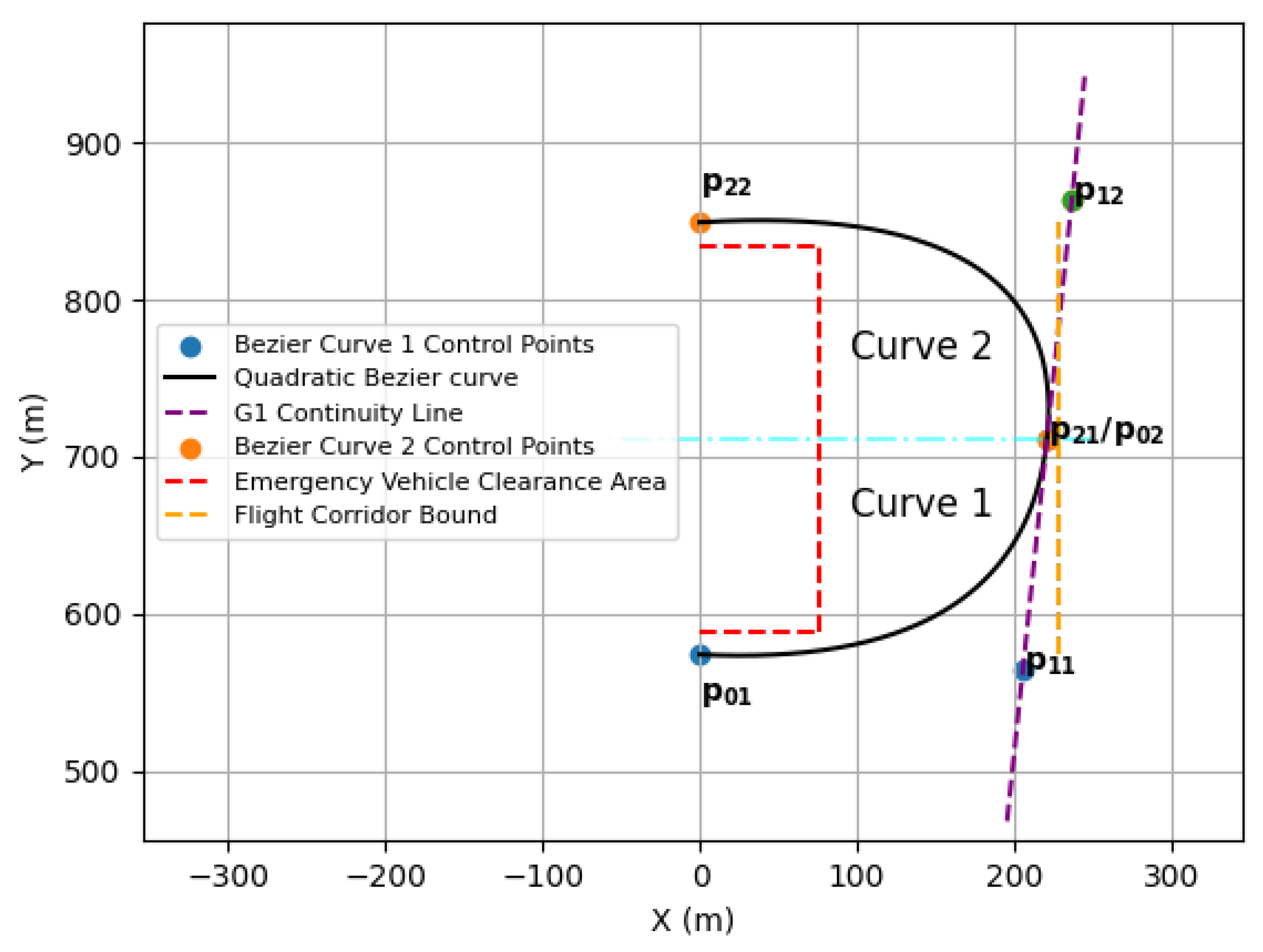
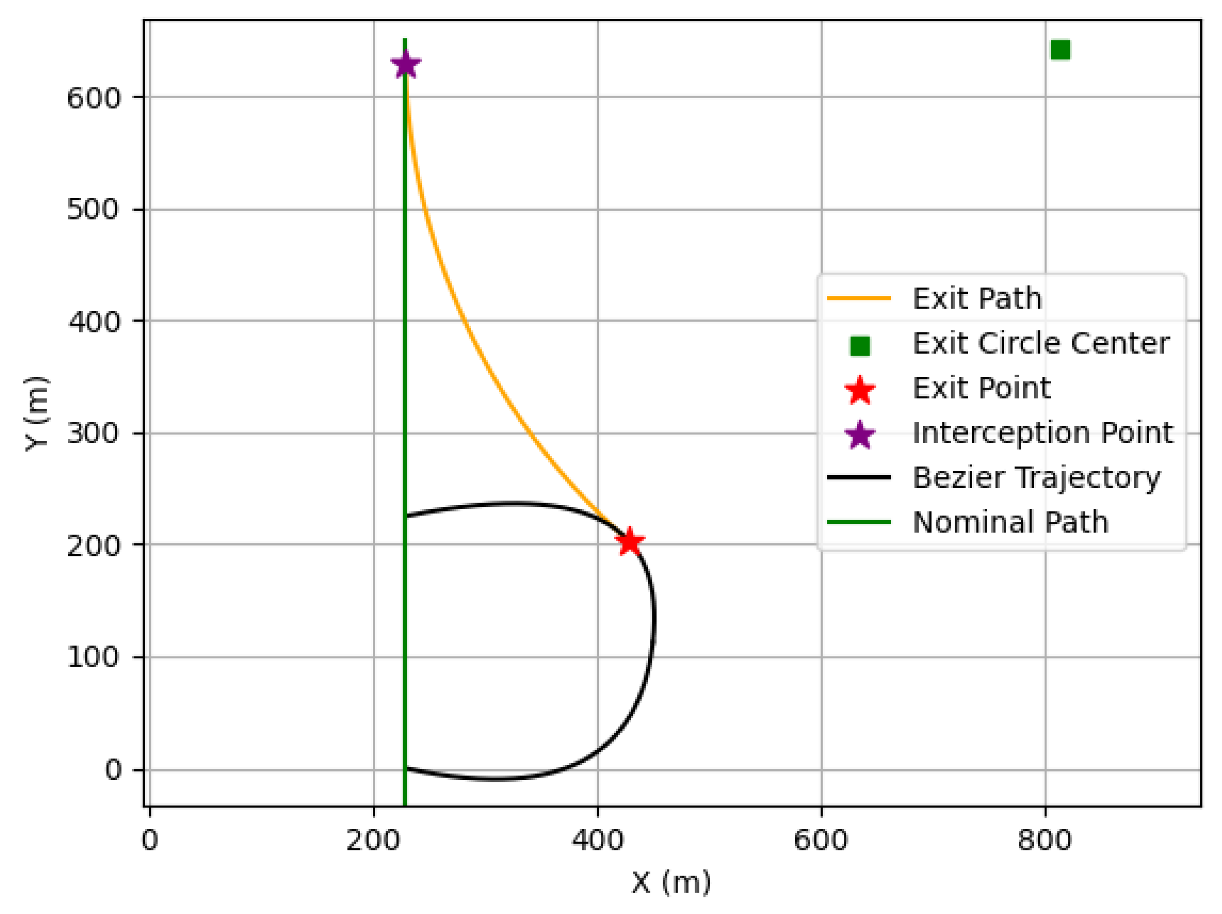
to be adjusted, and an alternate trajectory to be generated if the check failed. An example of two Bézier curves subject to G1 continuity and curvature constraints where
T is 5.3 s is shown in
Figure 1, where the emergency vehicle is granted a radius where other aircraft cannot fly, for safety. The light blue line shows the
y coordinate where first Bézier curve ends and the second begins. No additional constraints or weights were included in the optimization process, and explicit convergence thresholds were not defined. Multiple clothoids may provide a similar geometry to the Bézier curves, but clothoids may not perform as well when optimized for TOA. Generally, clothoids are optimized by changing the curve’s end point or curvature [
56], but when the endpoint is fixed or unknown, the clothoid optimization may fail or provide a geometry that violates the emergency vehicle’s clearance area. Numerical optimization of clothoids can also be more computationally expensive than for Bézier curves [
57], which may not be as beneficial when aiming for a lightweight optimization.
The method of generating and optimizing the quadratic Bézier curves allows for
T to be adjusted. Increasing or decreasing
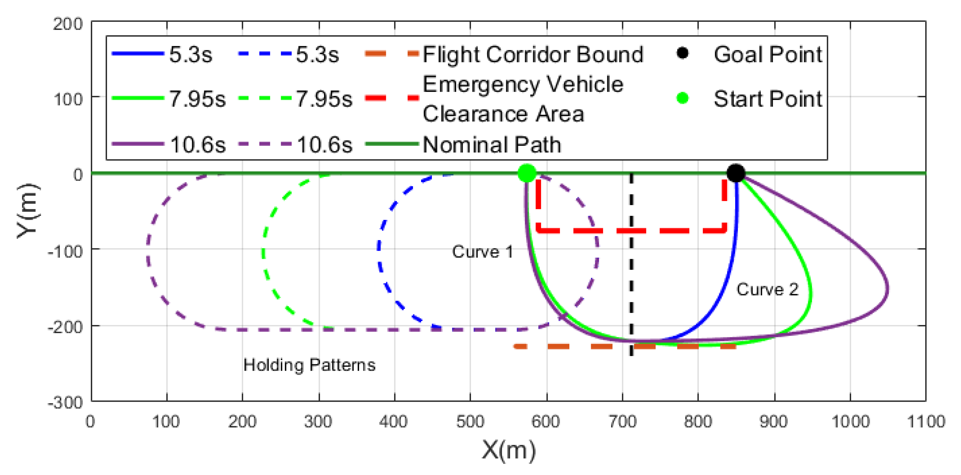
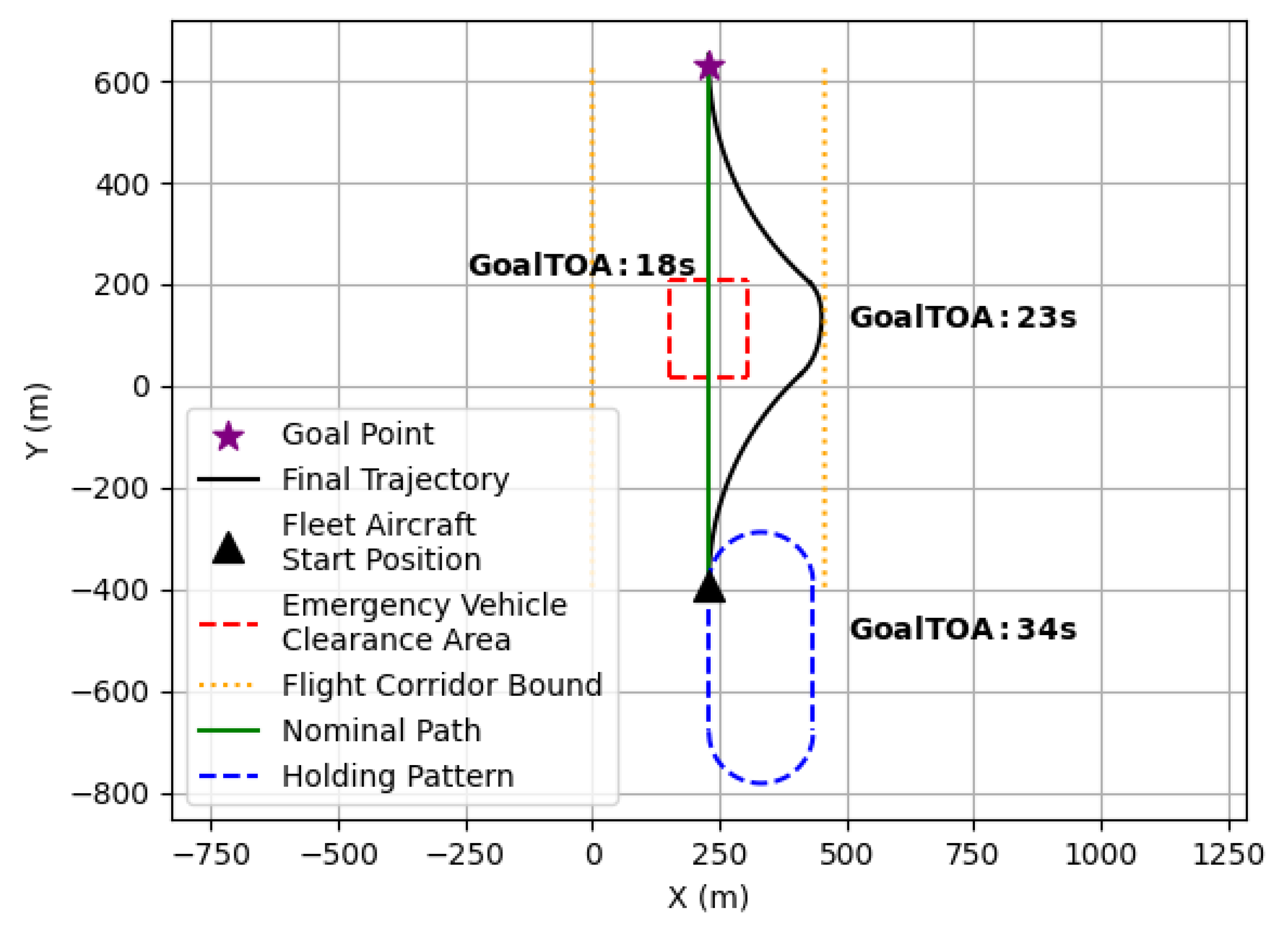
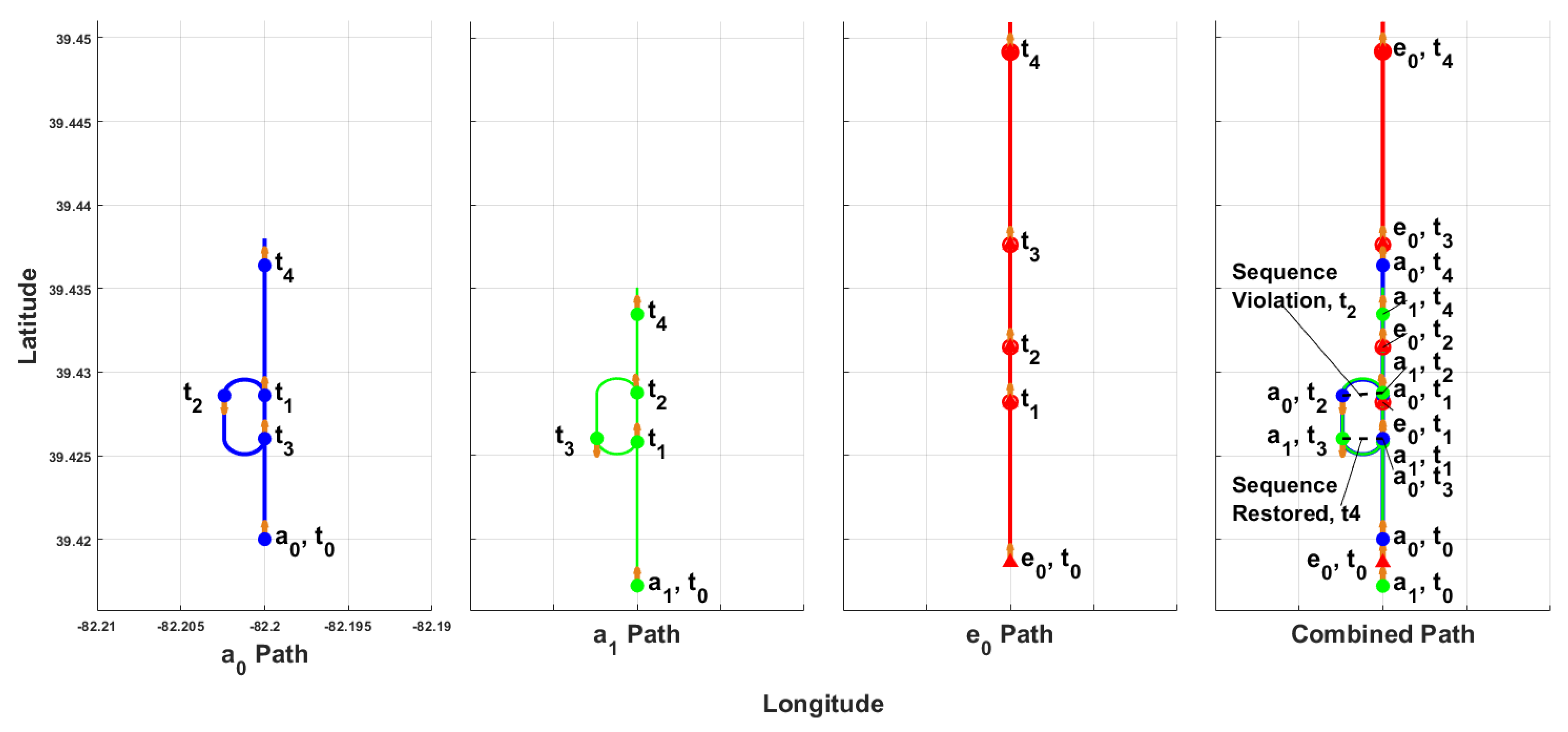
T changes the length of the Bézier curves so that the travel time of the trajectory is altered. Enabling control of an aircraft’s TOA during an alternate maneuver while still moving towards a goal may be crucial to minimizing delay when current flight procedures are to enter a holding pattern until the desired delay has been reached, which may cause sequencing issues between aircraft. Bézier trajectories with different
T values are compared to holding patterns with the same requested
T in
Figure 2. Aircraft following Bézier trajectories always move toward their goal point, whereas following a holding pattern causes them to move away, potentially leading to sequence violations, increased delays, and a higher risk of cascading delays.
While the Bézier trajectory itself was curvature-constrained to allow for fixed-wing aircraft with minimum turn radii to fly on it, these aircraft must begin intercepting the trajectory before reaching control point
or face the risk of not being able to utilize the trajectory. In the case of an emergency vehicle bypassing an approach pattern, when the time of impact (
) between a fleet aircraft and the emergency vehicle was 10 s, the fleet aircraft planned its Bézier trajectory 10 s ahead in time as its alternate maneuver. Commercial aircraft are considered to be in a conflict state when they are within five nautical miles of each other [
58]. Given that AAM aircraft will likely be 10–15 times smaller than commercial aircraft, the conflict range was proportionally reduced by 15, resulting in a separation threshold of 0.3 nautical miles for this study. Assuming AAM aircraft operate at speeds around 50–60 m/s, as suggested by [
59], this separation distance corresponds to approximately 10 s of flight time. The
between two aircraft is given by
where
d is the distance between aircraft in meters,
is the emergency vehicle’s velocity in m/s, and
is the fleet aircraft’s velocity in m/s. The fleet aircraft begins intercepting its Bézier trajectory when it violates the emergency vehicle’s safety radius. The interception of the Bézier trajectory requires the fixed-wing aircraft to perform a single-bank turn, modeled as a Dubins path segment, so that the aircraft heading at interception is accurate to the required heading of the Bézier curve.
The turn radius of a single bank turn in meters,
, can be given by
where
is the aircraft velocity in knots and
is the aircraft bank angle in radians [
60]. The velocity is assumed constant so
can be controlled by changing
, which changes the interception point on the Bézier path.
could be used to estimate the Dubins path, but multiple bank angles could produce a path that intercepts the Bézier trajectory at different points.
The metric for which bank angle to use for the interception path was selected based on the aircraft heading at the interception point on the Bézier trajectory. Interception heading could affect an aircraft’s ability to follow the Bézier trajectory accurately, so a bank angle that provides a minimal difference in heading between the required heading of the Bézier trajectory and the actual interception heading of the aircraft results in the cost function
:
where
is the required interception heading and
is the actual interception heading. Failure to accurately intercept the Bézier curves may result in a collision or significant delays as the aircraft attempts to intercept the trajectory at an alternate point. The cost function
is minimized when optimizing the Dubins entry and exit routes.
and aircraft performance constraints bound the result to be within a minimum and maximum, and the final bank angle is optimized with the SLSQP algorithm to produce a path that results in the minimum deviation between the heading at interception, a minimum value of
.
The aircraft initiates flight on its Dubins path when it violates a safety radius around the emergency vehicle; the fleet aircraft’s position could be used to find the center of the entry interception path. For a given bank angle, the interception path is
where
h and
k are the circle’s center,
is the aircraft’s
x position,
is the aircraft’s y position, and
and
are the x and y components of the Bézier curve, respectively, defined in [
25,
26]. Using Equations (6) and (7) for the entry path’s center allows for the entry path to be on either side of each fleet aircraft, which is necessary because collisions between aircraft may occur otherwise. To find the value of
that give the intersection point between the Bézier trajectory and the entry Dubins path at a given bank angle, Equation (
5) is solved. The required and actual heading at the intersection point are then calculated to result in
and
, respectively, for use in the cost function
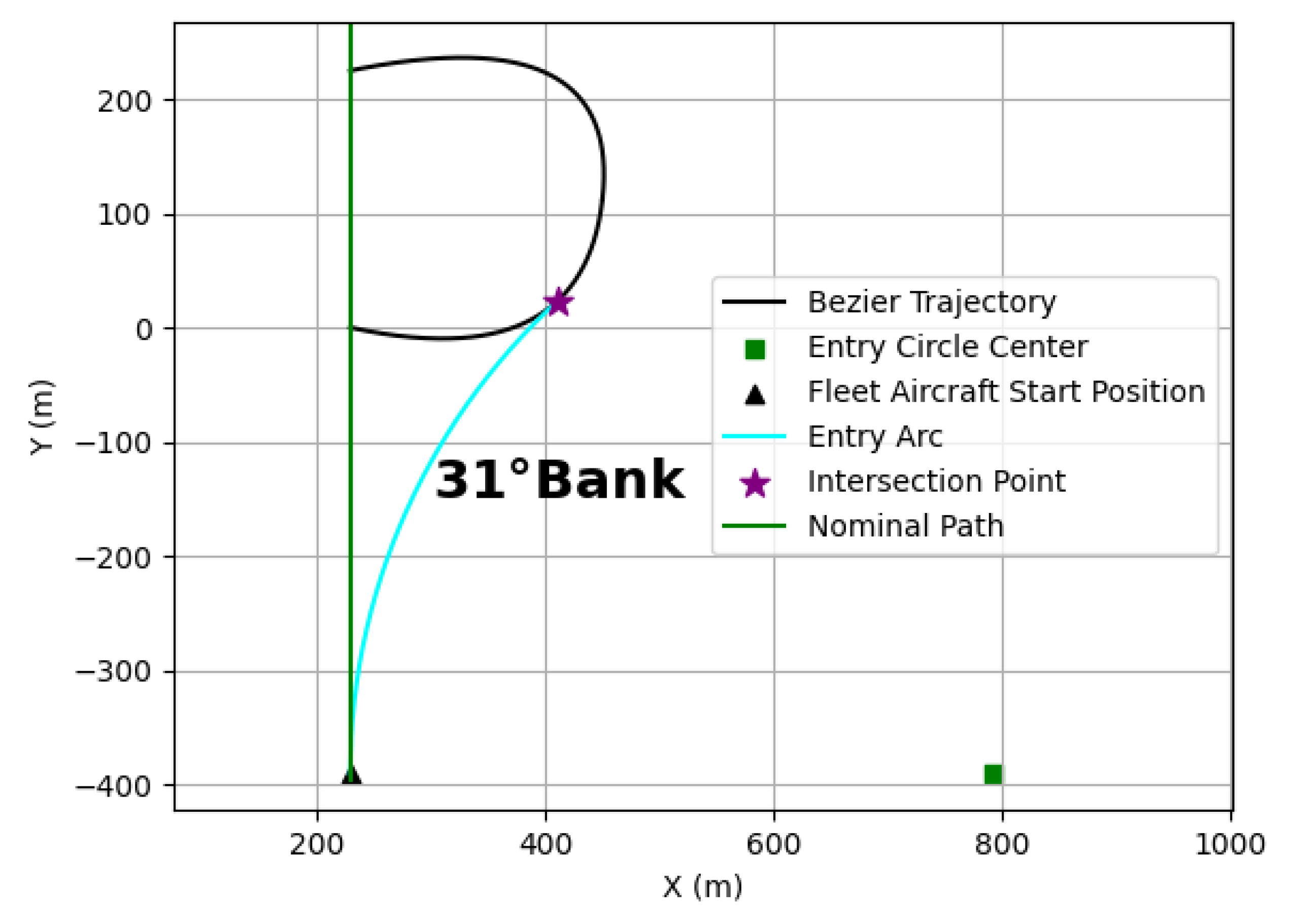
. An entry path where the fleet aircraft initiates flight at the (
x,
y) coordinate (229, −400) is shown in
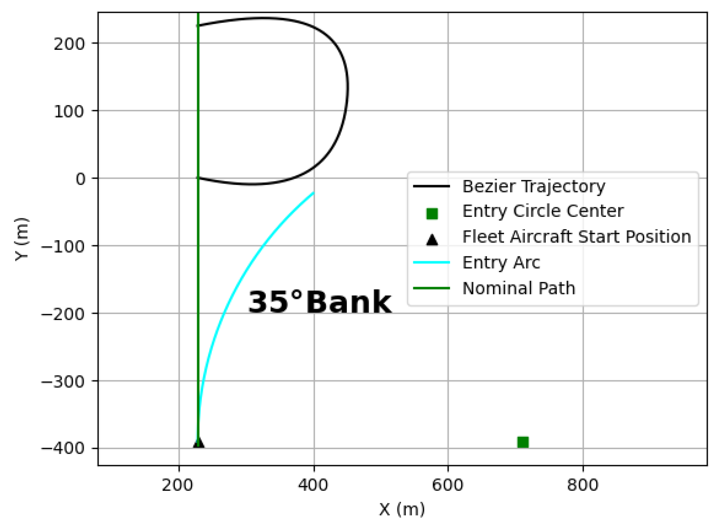
Figure 3, where the bank angle is optimized. If the fleet aircraft performed a different bank angle turn from the same starting point, the aircraft would not intercept the Bézier trajectory, as shown in
Figure 4. Not being able to intercept the Bézier trajectory could render the fleet aircraft unable to minimize its delay after initiating its alternate maneuver.
Finding the optimal Dubins path for exit from the Bézier trajectory is similar to the process for the entry path. The heading difference is found after calculating
in Equation (
5); however, the method of determining
h and
k, which has to be optimized, and the value of
in the cost function
, are different. When optimizing the exit Dubins path, the target for interception is the fleet aircraft’s nominal path instead of the Bézier trajectory. Similarly to the entry case, the exit path’s center depends on bank angle,
, and the aircraft’s position. The center of the exit Dubins path is given by
where
and
are representative of the aircraft’s position on the Bézier trajectory and
is the aircraft heading at
and
. In addition to finding the bank angle where the interception heading is most accurate, the point along the Bézier curve where the aircraft would exit needs to be optimized. The exit point of the Bézier trajectory needs to be optimized so that no excessive delays are absorbed in the traversal of the route and no collision between aircraft occurs. The equation for the exit Dubins path is, then, given by the following:
where
is the
x component of control point
, and
y is the intersection point along the nominal path. The intersection point,
y, is found at any bank angle by solving Equation (
10). In the exit case, the cost function
is used, where
is 90° and
is the aircraft heading,
.
is minimized while complying with minimum and maximum bank angle constraints and constraints with a minimum value for
. A minimum
is needed to guarantee that the fleet aircraft will not conflict with the emergency aircraft when intercepting the nominal path. Minimizing
results in an optimal bank angle for the exit of the Bézier trajectory, where the resulting exit Dubins path is shown in
Figure 5.
Using the entry path, Bézier trajectory, and exit path, an alternate maneuver trajectory is generated and shown in
Figure 6 along with a holding pattern, where the TOA from the fleet aircraft’s start to the goal point is shown for the Bézier trajectory, holding pattern, and nominal path. Holding patterns require aircraft to travel on the inbound and outbound legs for 5 s and use a maximum bank angle for the changes in direction. The fleet aircraft is moving with a constant velocity of 57 m/s with a maximum turn rate of 20°/s (bank angle of 73°) and minimum turn rate of 2.2°/s (bank angle of 20°). The aircraft velocity is reflective of predicted cruise speeds of AAM aircraft per [
59], and the turn rates were chosen as estimations of eVTOL turning capabilities and based off of FAA standard rate turns [
61,
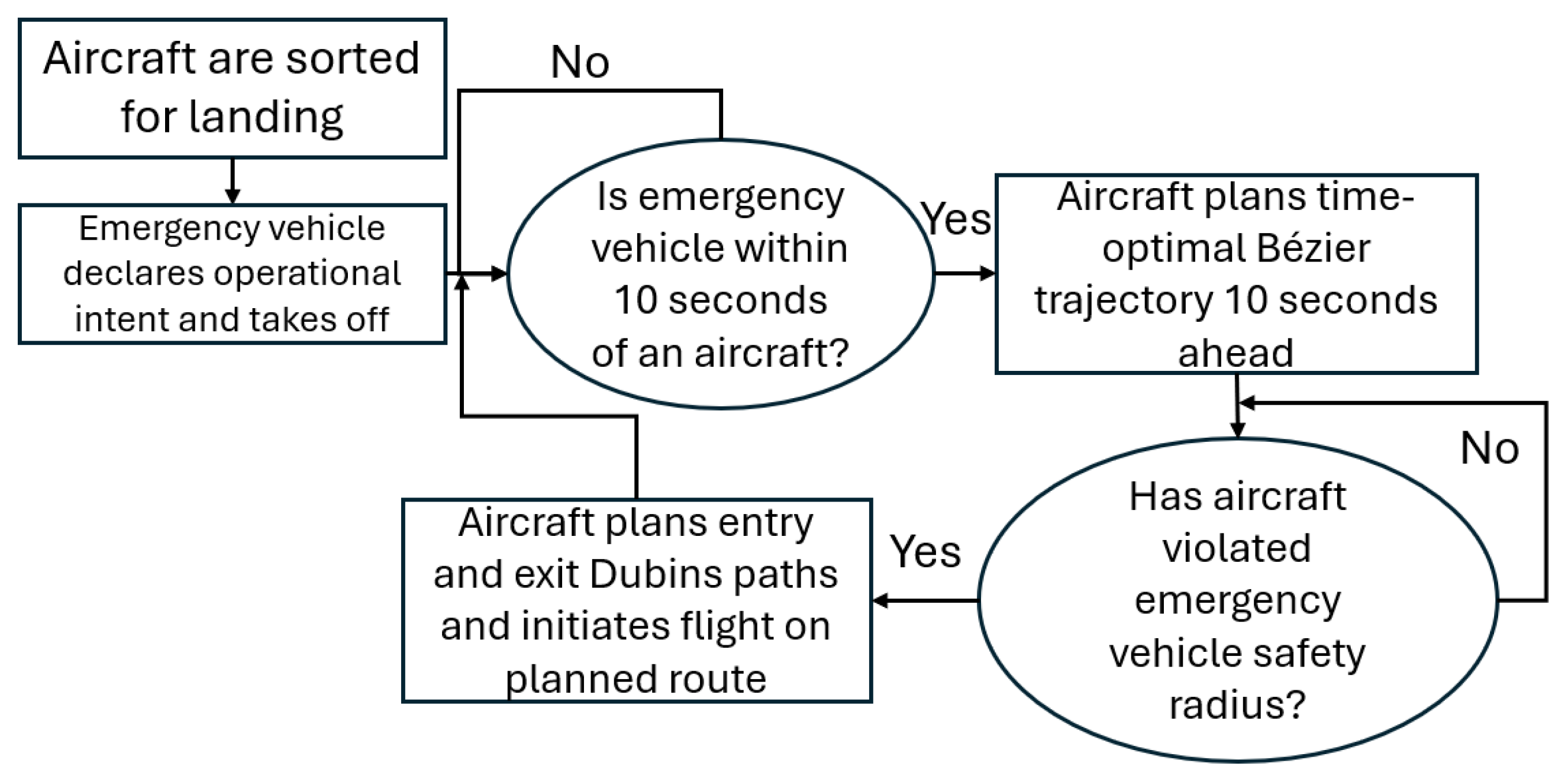
62]. The aircraft utilized a max turn rate for the holding pattern, and the Dubins paths for entry and exit each required a bank angle of 30°. The objective of this work was to minimize the cascading delay observed in queued aircraft undergoing cascading path replans with quadratic Bézier trajectory planning and Dubins path planning. The resulting time-optimal Bézier trajectory and heading-optimal Dubins paths could be used as an alternate maneuver when a path replan was necessary, where an example process diagram is presented in
Figure 7. After the emergency vehicle declares operational intent to bypass the fleet agents, each agent will measure its
to the emergency vehicle using Equation (
5). Once
between aircraft is 10 s or less, the Bézier trajectory is planned 10 s ahead of the fleet aircraft. When the fleet aircraft is within a certain threshold of the emergency vehicle, the entry and exit Dubins path segments are planned to form a final trajectory similar to the one shown in
Figure 6, and the fleet aircraft initiates flight on the newly planned route. Flight on the route was simulated in BlueSky version 1.0.4 using the Python version 3.12.10 API. The pure pursuit guidance law [
63,
64,
65,
66,
67] was used to generate heading commands for traversal of the Bézier trajectory, and a single heading command was given to the aircraft for traversal of the Dubins paths.
The proposed trajectory planning method was evaluated at varying initial distances between aircraft. However, to demonstrate the robustness of the model, the nondimensional parameter,
, can be introduced to relate the varied distance to aircraft velocity. The parameter
can be defined as
where
is the minimum separation between aircraft before a collision occurs,
and
are aircraft velocities,
is the simulation time-step, and
is the starting distance between aircraft.
3. Results
The first scenario, where an emergency vehicle bypasses only the leader of an aircraft fleet, and the second case, where an emergency vehicle bypasses the entire fleet, were simulated to validate the optimal automated trajectory tuning in situations known to cause a cascading path replan. For each flight, the fleet aircraft were five seconds apart, sequenced for landing, cruising in a straight line with a velocity of 57 m/s,
, and with a maximum turn rate of 20°/s (bank angle of 73°), minimum turn rate of 2.2°/s (bank angle of 20°), and a wing span of 16 m. The aircraft velocity was chosen to reflect predicted cruise speeds of AAM aircraft per [
59]; however, the proposed trajectory planning method would likely perform similarly to the current work under a range of fleet aircraft velocities. Changes may be seen in the radius of the Dubins path segments, Bézier trajectory curvature and length, and total delay times. The emergency vehicle cruised with a velocity of 64 m/s,
. The minimum separation between aircraft before a collision occurred,
, was 8 m, and the time-step,
, was 0.01 s. Fleet aircraft performed two alternate maneuvers: one where automated optimized trajectory tuning was used and one where a predefined holding pattern was initiated. Additionally, fleet aircraft were required to maintain their sequence throughout the flight; an alternate maneuver was initiated if the sequence was violated. After delay times from both the trajectory planning and holding pattern maneuvers were quantified, each scenario was simulated again with the spacing between aircraft adjusted. In the first scenario, the leader aircraft was moved closer to the emergency vehicle. In the second scenario, the distance between fleet aircraft was reduced.
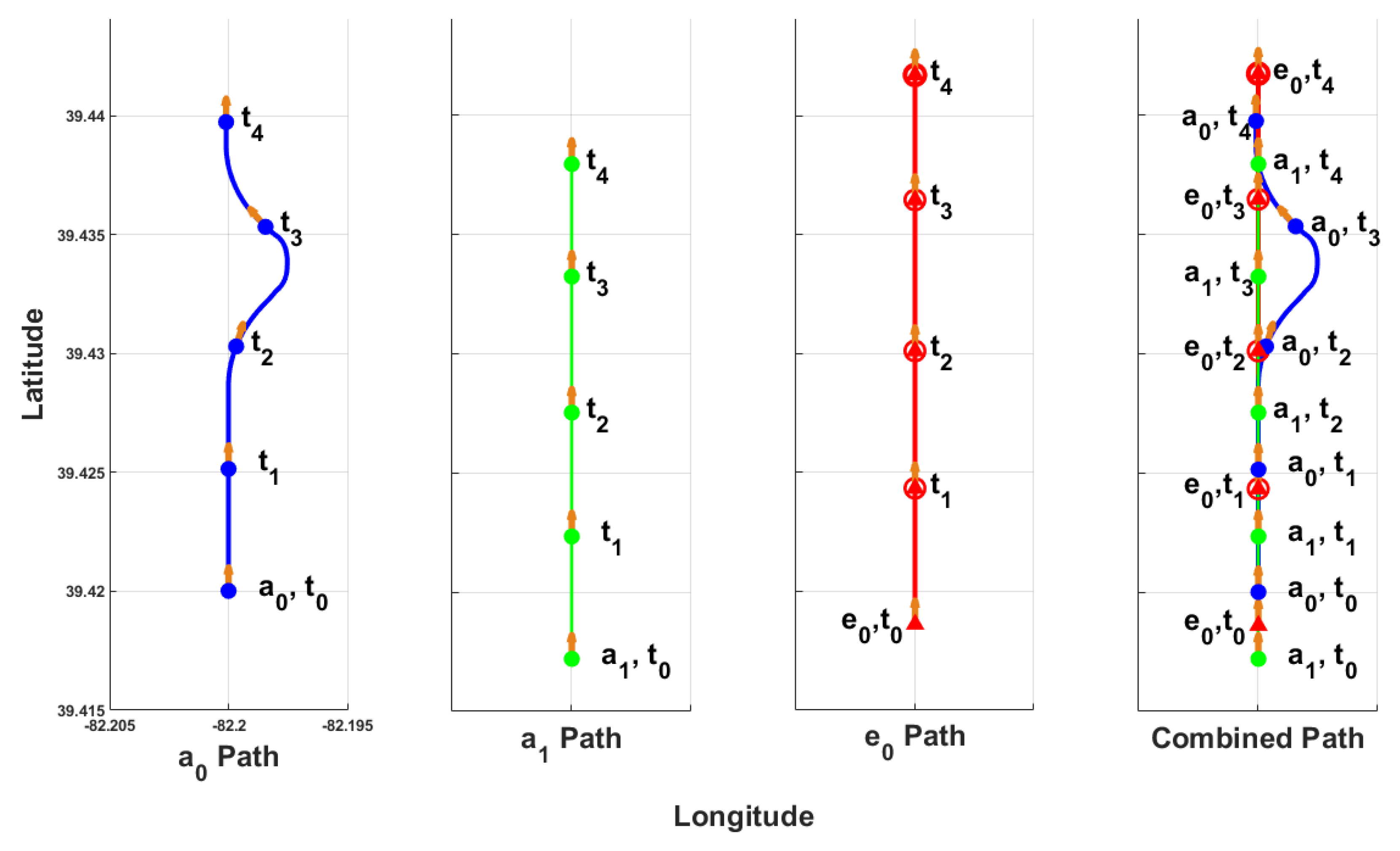
In the first scenario, the emergency vehicle,
, was placed between the lead and second aircraft,
and
, respectively, as seen at time-stamp
in
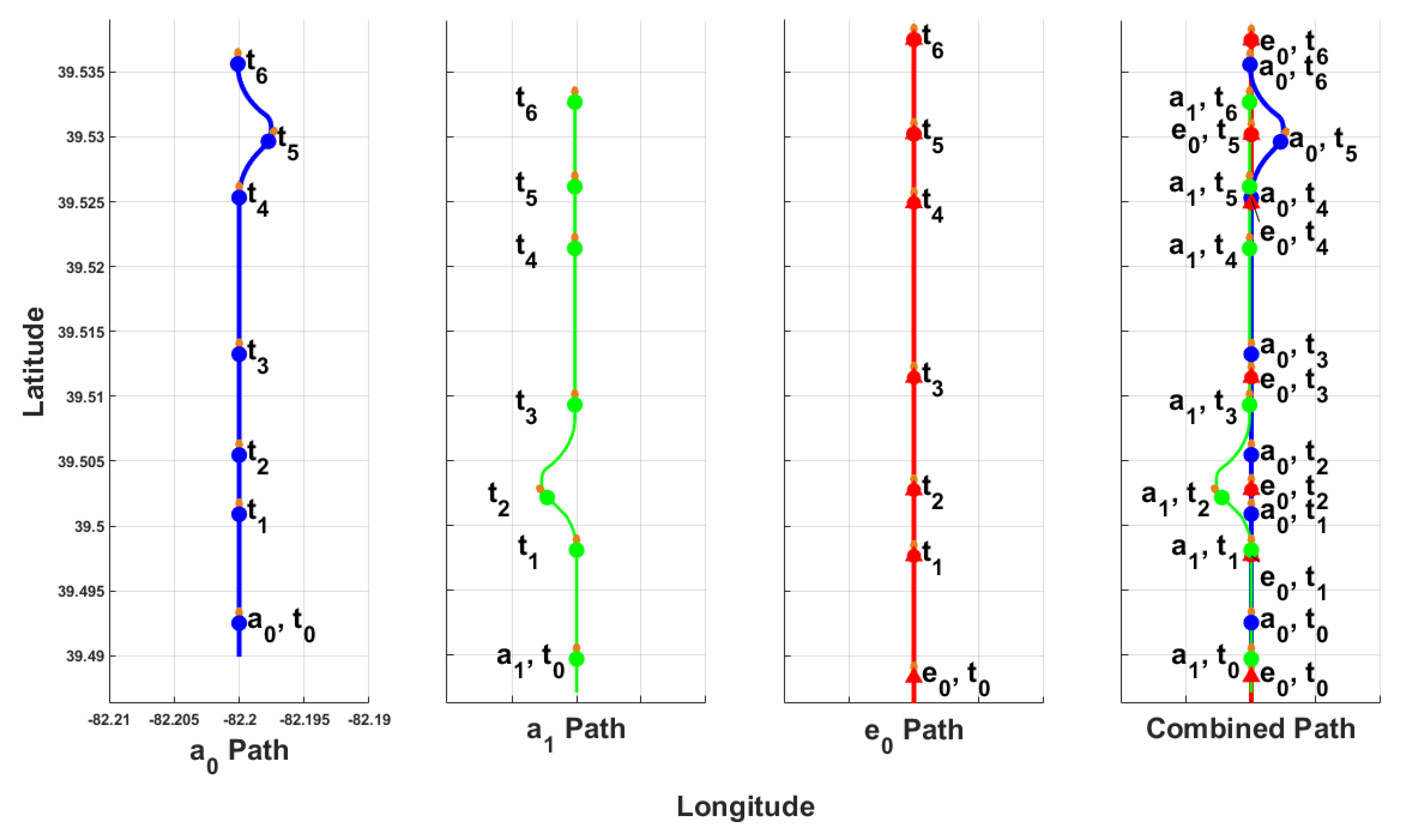
Figure 8, which shows a time-lapse for the Scenario 1 flight where blue lines and points represent
, green lines and points represent
, and red lines and points represent
. When
was with within 10 s of
,
planned its Bézier trajectory. The interception Dubins paths were planned, and the path flight was initiated when
violated the emergency vehicle’s safety radius, shown at
in
Figure 8. At
,
began to intercept the nominal path after performing its alternate maneuver, successfully allowing the emergency vehicle to perform a bypass. Time-stamp
shows
resuming flight on the nominal path, maintaining its sequence with respect to
.
A second flight with the same starting conditions where a holding pattern is initiated as the alternate maneuver, instead of the Bézier trajectory, was conducted for comparison with a time-lapse of the flight shown in
Figure 9 where blue lines and points represent
, green lines and points represent
, and red lines and points represent
. At
,
violated the emergency vehicle’s safety radius and initiated flight on its pre-planned holding pattern, which involved a max-bank turn until the aircraft heading was 180°, flight in a straight line for at least 5 s until
had passed, and a max-bank turn until aircraft heading was 0°. Performing the alternate maneuver allowed for the bypass of
. At
,
passed
, violating the landing sequence, thus requiring
to initiate a holding pattern similar to that of
.
was not allowed to exit the straight segment of its holding pattern until
resumed flight on the nominal path and was ahead of
. At
,
was on the nominal path and ahead of
, allowing
to initiate its max-bank turn to resume flight on the nominal path, as shown in
Figure 9. All aircraft, in the correct sequence after performing their alternate maneuvers, are shown at
in
Figure 9.
When the Bézier alternate maneuver was utilized,
was delayed by 1.9 s, and
absorbed no delay because it did not need to perform an alternate maneuver. When a holding pattern was used, a cascading delay effect appeared in the aircraft fleet, where
was delayed by 20.4 s and
was delayed by 20.6 s. Each aircraft’s total delay is shown in
Figure 10. Utilizing the Bézier trajectory planning method reduced the delay absorbed by
by 91% and reduced
’s delay by 100% because it did not have to perform an alternate maneuver.
Additionally, the relationship between initial aircraft spacing and delay times was studied by changing the starting position of
with respect to
. Values of
= 64 m/s and
= 57 m/s were used in Equation (
11) to calculate the nondimensional parameter
that relates initial spacing between aircraft to aircraft velocity. Each flight was performed again where the starting distance between
and
,
, ranged from 104 m to 8 m, incrementing by 8 m in each flight. Delay times for
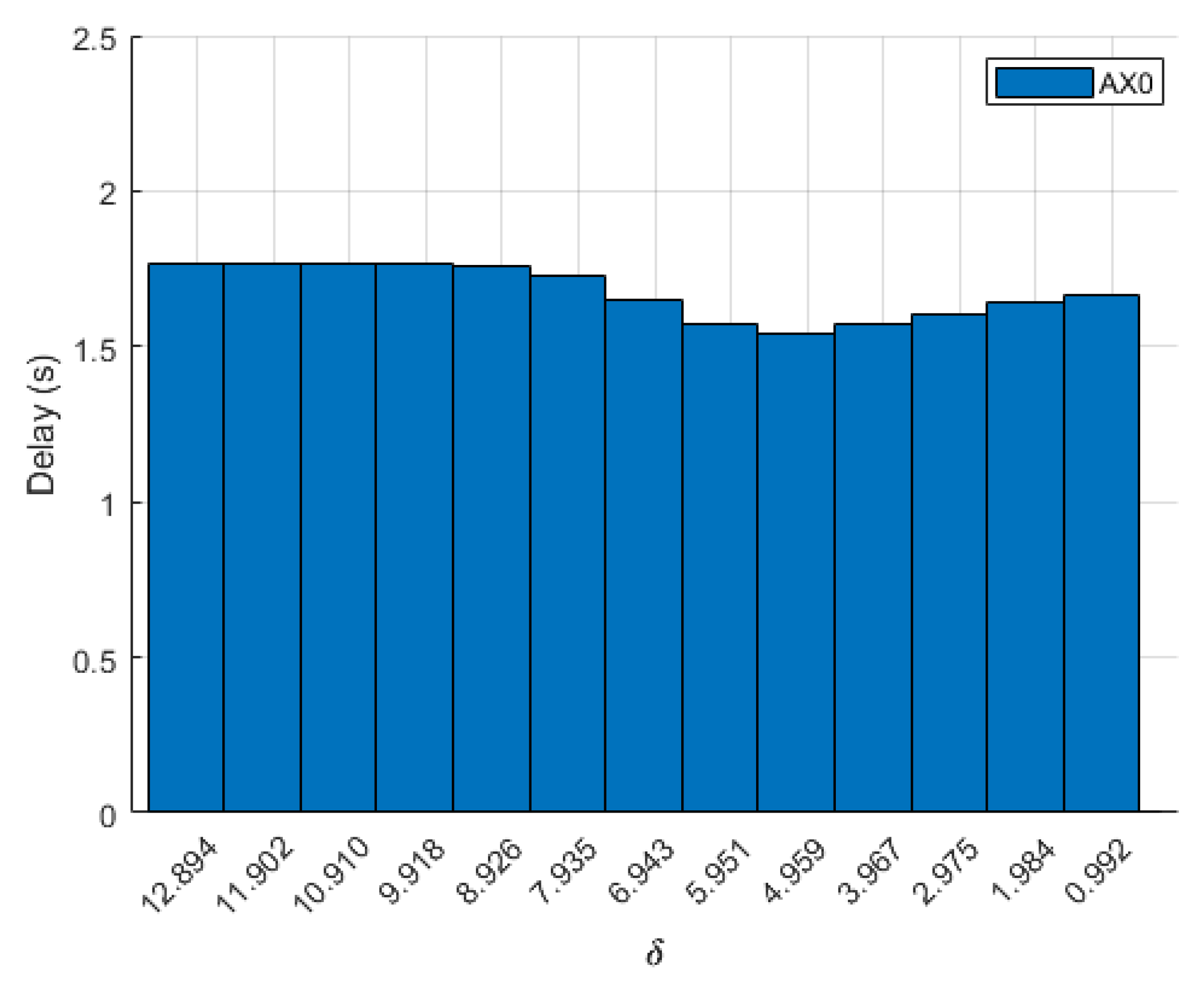
when the Bézier trajectory was used are shown in
Figure 11; the delay for
is not shown because it remained at 0 s across all flights. As the distance between
and
decreased, there was no clear trend in delay times. Delays decreased when aircraft spacing was between 80 and 40 m but increased from 32 to 8 m. Differences in delay times are due to the point at which the entry Dubins segment intercepted the Bézier curve. When a holding pattern was utilized, delay times for
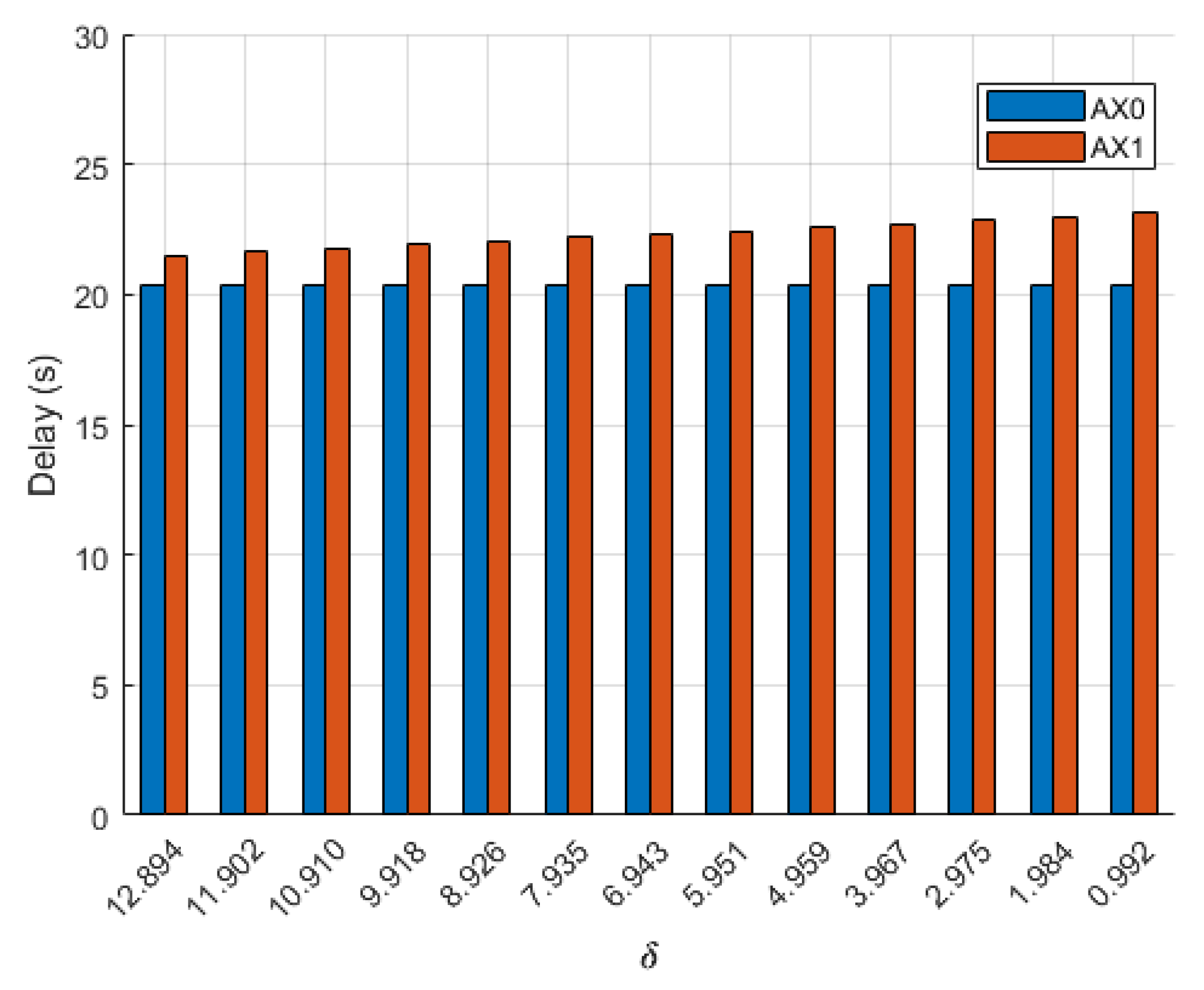
remained constant, but delay absorbed by
showed an inverse relationship with spacing, meaning as spacing between
and
decreased, delay for
increased, as shown in
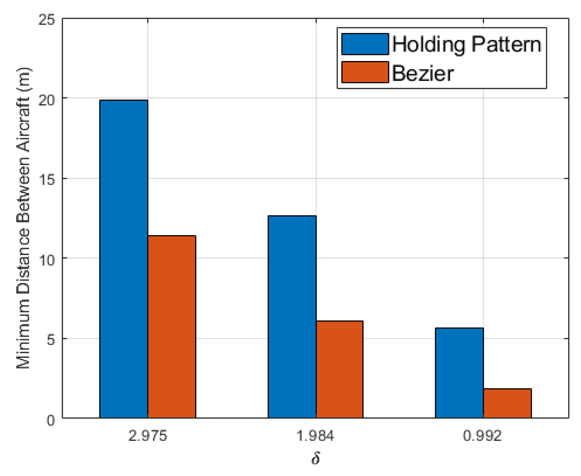
Figure 12. While the Bézier alternate maneuver greatly reduced delay times, it sacrificed the distance between
and
. The distance between each aircraft was recorded at each time-step of simulation, and the minimum allowable distance between aircraft before identifying a collision,
, was 8 m, half of the aircraft’s wing span. The use of the Bézier alternate maneuver caused a collision between
and
in two flights where the initial spacing between aircraft was 8 m and 16 m, but the only collision when using the holding pattern was when the initial spacing was 8 m, as shown in
Figure 13.
The emergency vehicle
was placed behind the last aircraft in the fleet,
, seen at
in
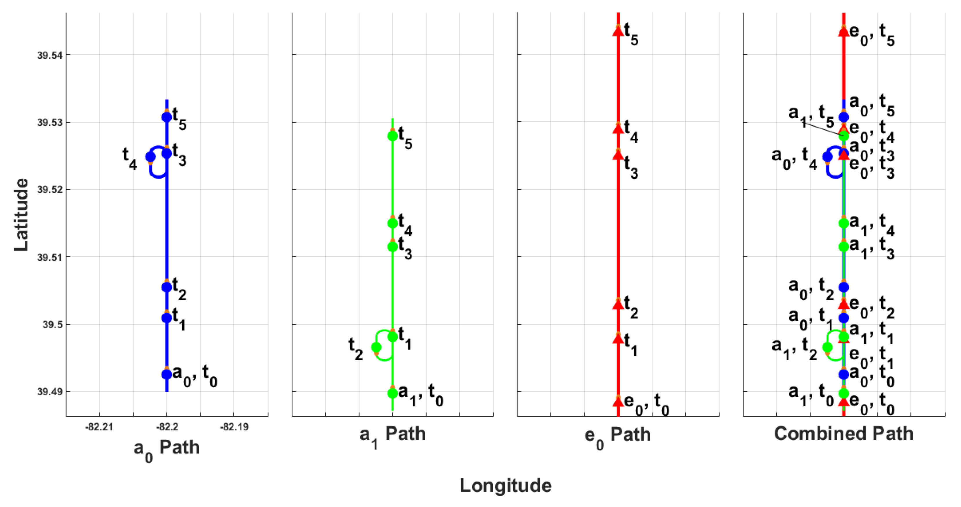
Figure 14 where blue lines and points represent
, green lines and points represent
, and red lines and points represent
. When
was within 10 s of
, it planned its alternate Bézier path. At time-stamp
, when
violated
EX0’s safety radius,
planned and initiated a flight on its Dubins entry path. At
,
resumed flight on the nominal path, successfully allowing
to bypass while maintaining its sequence. Similarly to
,
began performing its alternate maneuver at
after planning its Bézier and Dubins paths.
planned the alternate maneuver on the right side of the flight corridor, whereas
planned the alternate maneuver on the left side. Both aircraft in the fleet planned and flew on an optimal alternate maneuver so that
could bypass the fleet while
and
maintained sequence, as shown at
in
Figure 14.
A second flight with the same starting conditions, where a holding pattern was initiated as the alternate maneuver instead of the Bézier path, was conducted for comparison with a time-lapse of the flight shown in
Figure 15 where blue lines and points represent
, green lines and points represent
, and red lines and points represent
. At
,
violated the emergency vehicle’s safety radius and initiated flight on its pre-planned holding pattern. The holding pattern required the aircraft to initiate a max-bank turn until the aircraft heading was 180°, flight on the inbound leg for at least 5 s until
had passed, and a max-bank turn until the aircraft heading was 0°. Performing the alternate maneuver allowed for a bypass of
, as seen at
. At
,
violated
EX0’s radius and initiated its alternate maneuver to allow
to pass. Time-stamp
in
Figure 15 shows
and
maintaining their sequence after they both perform an alternate maneuver to allow for a bypass of the emergency vehicle.
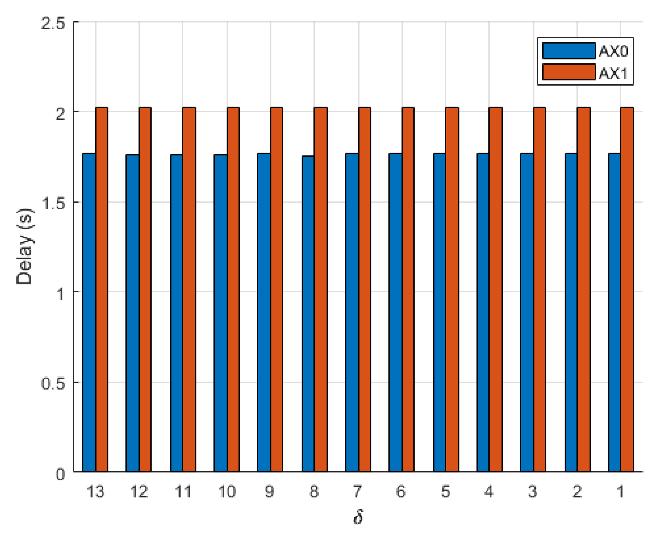
When the Bézier alternate maneuver was utilized,
was delayed by 1.9 s, and
was delayed by 2.1 s. Even though both aircraft used the same methods for planning the alternate maneuver, slight differences between paths caused a variation in delay. When a holding pattern was used, no cascading delay effect was observed, and each aircraft was delayed by 20.4 s.
had its delay reduced by 91%, and
had its delay reduced by 90% when using the Bézier maneuver. Each aircraft’s total delay is shown in
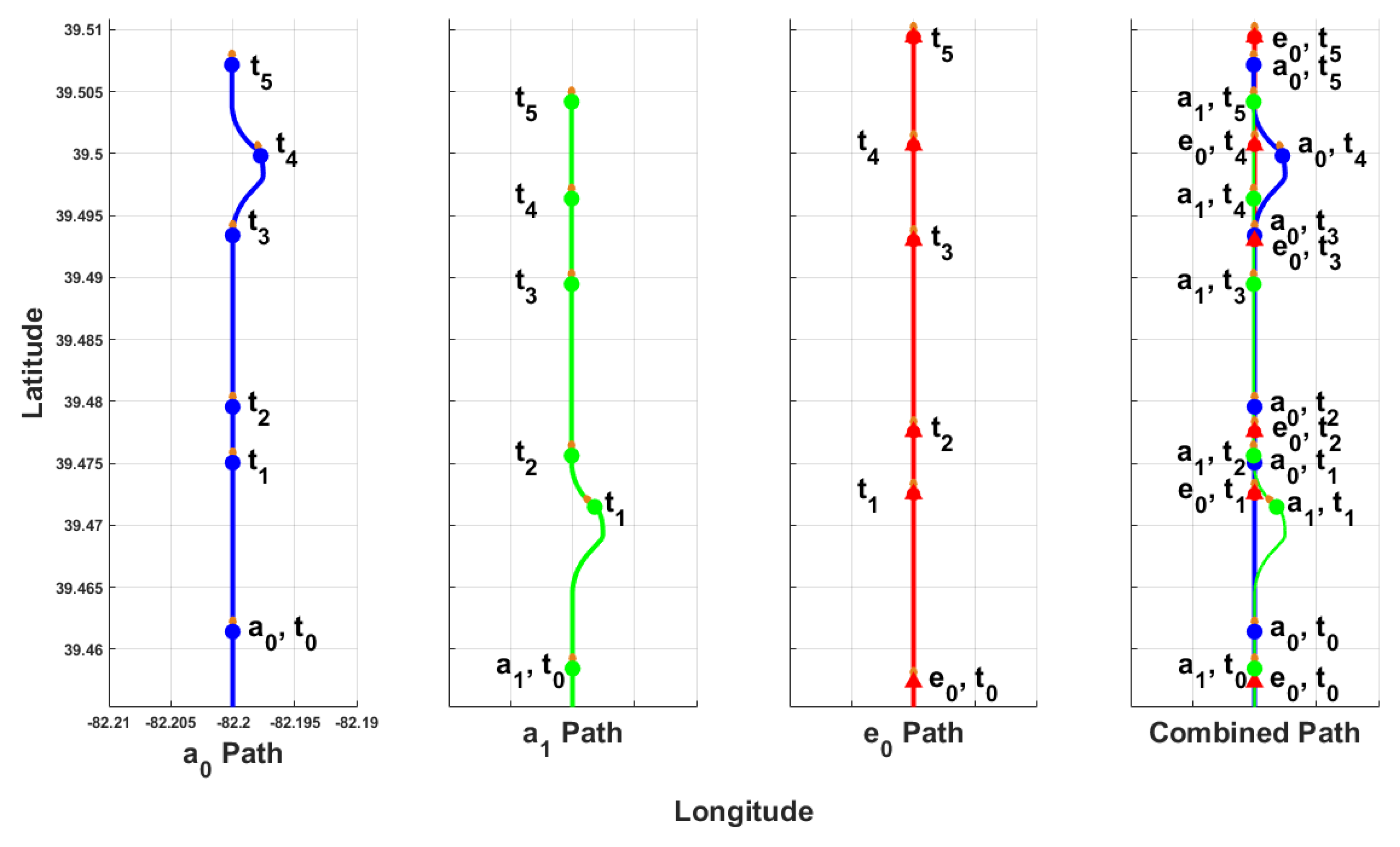
Figure 16. If both Bézier paths had been planned on the right side of
and
, as shown in
Figure 17, delay times for the two aircraft would have been more similar.
The relationship between aircraft spacing and delay times was studied by changing the starting position of
with respect to
. In this scenario, values of
=
= 57 m/s were used in Equation (
11) to calculate the nondimensional parameter
that relates initial spacing between aircraft to aircraft velocity. Each flight was performed again where the starting distance between
and
ranged from 104 m to 8 m, incrementing by 8 m each flight. Delay times for each aircraft, when the Bézier trajectory was used, are shown in
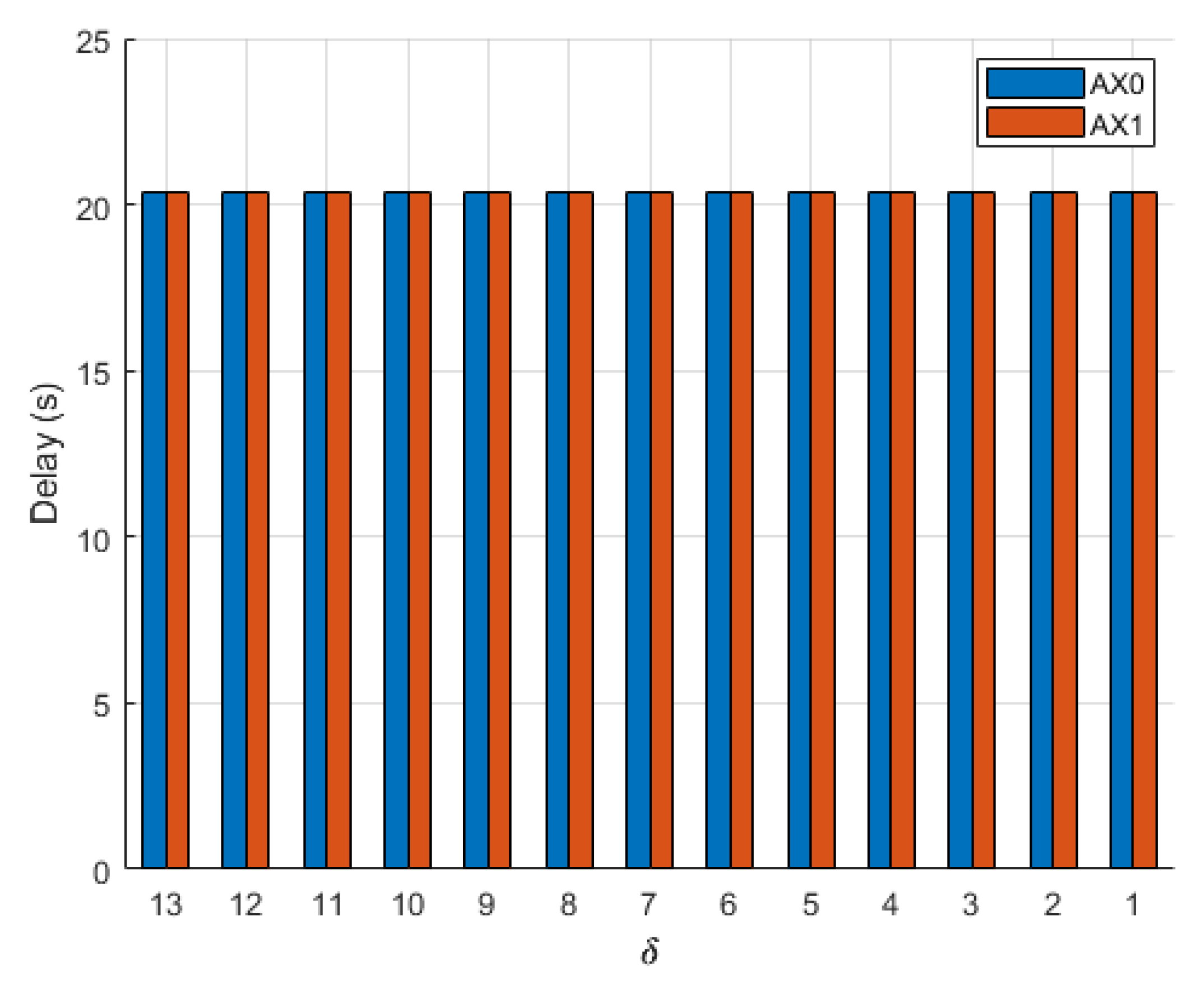
Figure 18, where there was no change in delay times for either aircraft regardless of the initial distance between them. When a holding pattern was utilized, delay times for
and
also remained constant, as shown in
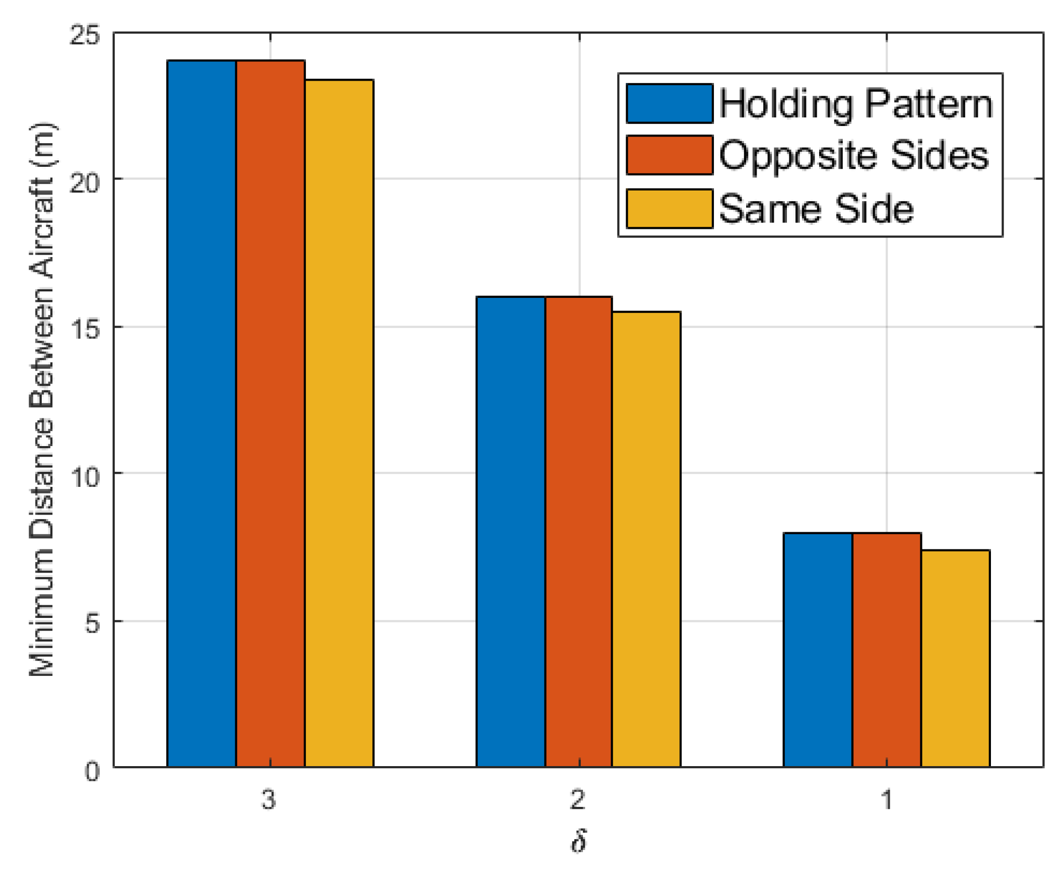
Figure 19, but were much larger than the Bézier delay times. However, the use of the Bézier alternate maneuver caused a collision between
and
in one flight, where the initial spacing between aircraft was 8 m, and the Bézier trajectories were planned on the same side. There were no collisions when the Bézier curves were generated on opposite sides of each other or when a holding pattern was used as shown in
Figure 20.
