Article

The Dynamic Response of Aluminum Alloy Plates Subjected to Multiple-Fragment Impacts Under Pre-Tensile Loading: A Numerical Study

Aviation Engineering School, Air Force Engineering University, Xi’an 710043, China
*
Author to whom correspondence should be addressed.
Aerospace 2025, 12(4), 353; https://doi.org/10.3390/aerospace12040353
Submission received: 5 March 2025 / Revised: 8 April 2025 / Accepted: 14 April 2025 / Published: 17 April 2025

Abstract

:
This study presents an innovative numerical investigation into the synergistic effects of pre-tensile loading and multi-fragment hypervelocity impacts on thin-walled 7075-T6 aluminum alloy structures, addressing a critical gap in aircraft survivability design under realistic combat conditions. Utilizing an advanced finite element framework with stress dynamic relaxation preloading, the established model was rigorously validated against experimental gas-gun impact data, achieving less than 11% deviation in residual velocity. Distinct from prior single-impact studies, our work pioneers a systematic multi-parameter analysis encompassing multiple pre-stress levels, circumferential/linear fragment distributions, velocity gradients, and geometries. The findings of this parametric study establish a linkage between dynamic penetration mechanics and operational airframe stresses, offering guidelines for damage-tolerant design optimization in aircraft structures.

1. Introduction

Combat aircraft are the cornerstone of air combat operations, and their operational readiness and loss rates significantly influence the outcome of warfare. As technology has advanced, high-speed fragmentation from warheads has increasingly supplanted high-caliber machine guns and cannons as the primary threat to aircraft. Consequently, aircraft combat survivability has emerged as a critical design criterion for military aircraft across nations. A comprehensive survivability assurance system has been established, encompassing multiple dimensions such as design standards, testing facilities, and evaluation methodologies [1].
The investigation of structural terminal effects has long been a critical focus in the research on equipment survivability. Scholars have extensively examined the damage mechanisms and effects of various structures for different lethal elements [2,3,4,5]. In the context of multiple-impact responses, Qian et al. [6,7] employed theoretical modeling and finite element numerical simulations to conduct a detailed analysis of the damage mechanisms and plugging formation in armored steel plates subjected to fragment clusters. Shen et al. [8] utilized experimental and numerical methods to study the multiple ballistic performance of ceramic/metal composite armor, determining the optimal adhesive layer thickness. Qiang et al. [9] investigated the multiple ballistic resistance of fully fixed 304 stainless steel plates by using finite element methods. Paredes-Gordillo et al. [10] developed a numerical model for multiple impacts on carbon fiber-reinforced plastic (CFRP), examining its response to stress waves. Göde et al. [11] studied the dynamic response of Armox 600T armor steel to 7.62 mm × 51 mm M61 AP bullets under multiple-impact conditions through ballistic tests and high-resolution optical scanning. In aircraft thin-walled structures subjected to fragment clusters or rapid-firing gun projectile groups, the aircraft experiences multiple impacts within a short time frame, often resulting in significant damage effects [12], as illustrated in Figure 1.
During missile–target interception, combat aircraft frequently execute high-intensity evasive maneuvers (e.g., rapid turns and abrupt acceleration/deceleration), inducing substantial tensile stresses in critical structural components such as wing skins, fuselage panels, and control surfaces. These pre-existing tensile loads significantly alter the stress state of the aluminum alloy structures, thereby modifying their dynamic response to fragment impacts. M. Rathnasabapathy et al. [13] investigated the dynamic response of fiber metal laminates (FMLs) under tension preloading by using finite element models. Kumar et al. [14] studied the high-speed impact response of carbon–glass composite materials under normal and hydrostatic preloading conditions, complemented by mechanical strength tests. Xu et al. [15] conducted ballistic impact tests on CFRP laminated panels penetrated by rigid spheres at various impact velocities, with tests performed under three preloading conditions: uniaxial tension, uniaxial compression, and no preloading. They developed an energy absorption-based theoretical model to predict the influence of preloading conditions on the ballistic limit. Gurgen et al. [16] considered multiple variables, including preloading conditions, inclination angles, and impact speeds, in their finite element numerical simulations of 7075-T6 aluminum alloy target plates. García-Castillo et al. [17] applied a 51 kN pre-tension load to aluminum alloy plates by using specially designed fixtures and conducted ballistic impact tests. Unstable cracks that could lead to catastrophic failure were observed in the preloaded plates. The ballistic limit was estimated by using the least squares method based on the relationship between impact velocity and residual velocity, revealing no significant differences between the two loading conditions.
Currently, aluminum alloy remains an indispensable material for various aircraft due to its superior properties and advantages. It continues to constitute a significant proportion of aircraft structures [18]. Considering the loading conditions experienced by aircraft structures during actual target–missile interception, research on the dynamic response of structures subjected to multiple impacts under load is still relatively limited. In particular, experimental designs require large-scale force-loading equipment and multi-barrel ballistic launch systems, which significantly increase the experimental cost. This study focuses on the dynamic response of typical aluminum alloy thin-walled plate structures under pre-tensile loading conditions and conducts multi-fragment impact research. By using numerical simulation methods, a finite element simulation model based on stress dynamic relaxation preloading is established. The model’s reliability was validated through comparisons with experimental data from the gas-gun impact tests in Reference [17]. By considering factors such as fragment distribution patterns, velocity gradients, and loading levels, this paper provides a detailed investigation into the dynamic response mechanisms of aluminum alloy thin plates under pre-tension conditions. The findings of this study can provide valuable insights for aircraft battle damage repair, assessment, and survivability design.

2. Numerical Simulation

With the increasing maturity of computer-aided engineering (CAE) technology, numerical simulation has gained significant popularity among researchers due to its comprehensive and versatile analysis capabilities and relatively low application costs across various fields. Numerical simulation has become an indispensable tool for investigating impact problems. For the complex conditions involving preloaded stress fields and multiple-projectile impacts in this study, numerical simulation can effectively model various operating scenarios and validate the simulation models through simulated impact tests at lower time and cost compared with physical experiments. This section presents the development of a multi-fragment impact response simulation model for aluminum alloy thin-walled structures under pre-tensile loading conditions using LS-DYNA software (Ver. R13). The reliability of the model is verified by comparing it with experimental results.

2.1. Numerical Simulation Setups
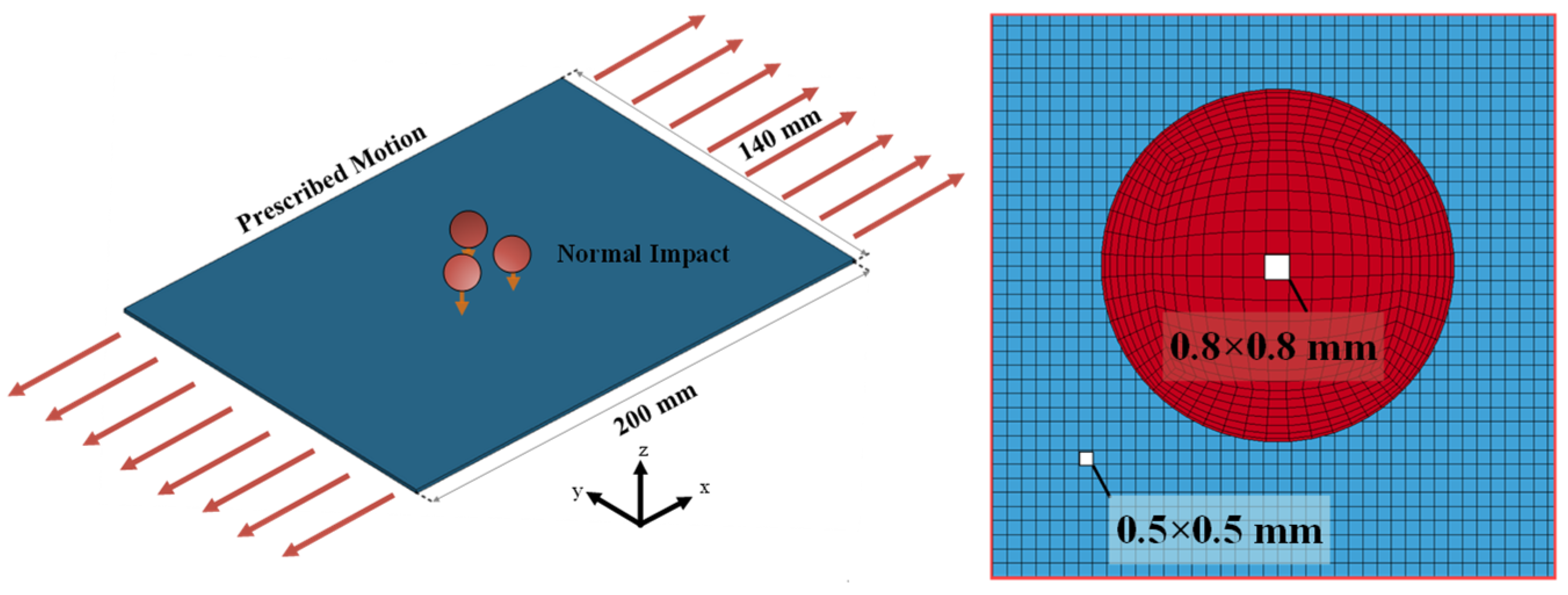
2.1.1. Model Setup

The target plate in the model measures 200 mm × 140 mm × 1.5 mm and is uniformly meshed with 0.5 mm × 0.5 mm solid elements, resulting in a total of 33,600 elements. The fragment is modeled as a 12.5 mm diameter sphere, discretized into six equal segments using 0.8 mm × 0.8 mm solid elements, yielding a total of 23,625 elements. The short ends of the target plate are subjected to loading by controlling the displacement of end nodes by using the *BOUNDARY_PRESCRIBED_MOTION_SET and *DEFINE_CURVE keywords, as illustrated in Figure 2. To prepare the pre-impact loaded state of the target plate, the dynamic relaxation method is employed. This phase is controlled via the *CONTROL_DYNAMIC_RELAXATION and *CONTROL_IMPLICIT keywords, ensuring the uniform distribution of the global load on the target plate during the implicit analysis stage. The contact interaction between the fragment and the target plate is characterized by using the *CONTACT_ERODING_NODES_TO_SURFACE keyword. All nodes of the fragment are grouped into a node set and defined as the slave surface, while the target plate part serves as the master surface. This approach accurately represents the contact relationship during the impact process and effectively minimizes initial infiltration phenomena.
Considering the inherent randomness in the distribution of multiple-fragment impacts, the model incorporates a range of loading levels and distribution patterns, as illustrated in Figure 3. Although the loading during aircraft maneuvering is dynamic, when compared with the microsecond-scale process of fragment impact on aircraft structures, the structural load state can be considered unchanged. The Johnson–Cook model parameters for AA7075-T6 define a static yield strength of 448 MPa in this model (Table 1). By controlling the motion of the endpoints to 1 mm, 1.2 mm, and 1.5 mm, three distinct global stress levels of sub-yield (370 MPa), near-yield (440 MPa), and over-yield (458 MPa), respectively, were achieved, systematically spanning three critical mechanical regimes. In this study, the specimen orientations depicted in all figures are consistently aligned with the reference configuration defined in Figure 3 (unless otherwise annotated).

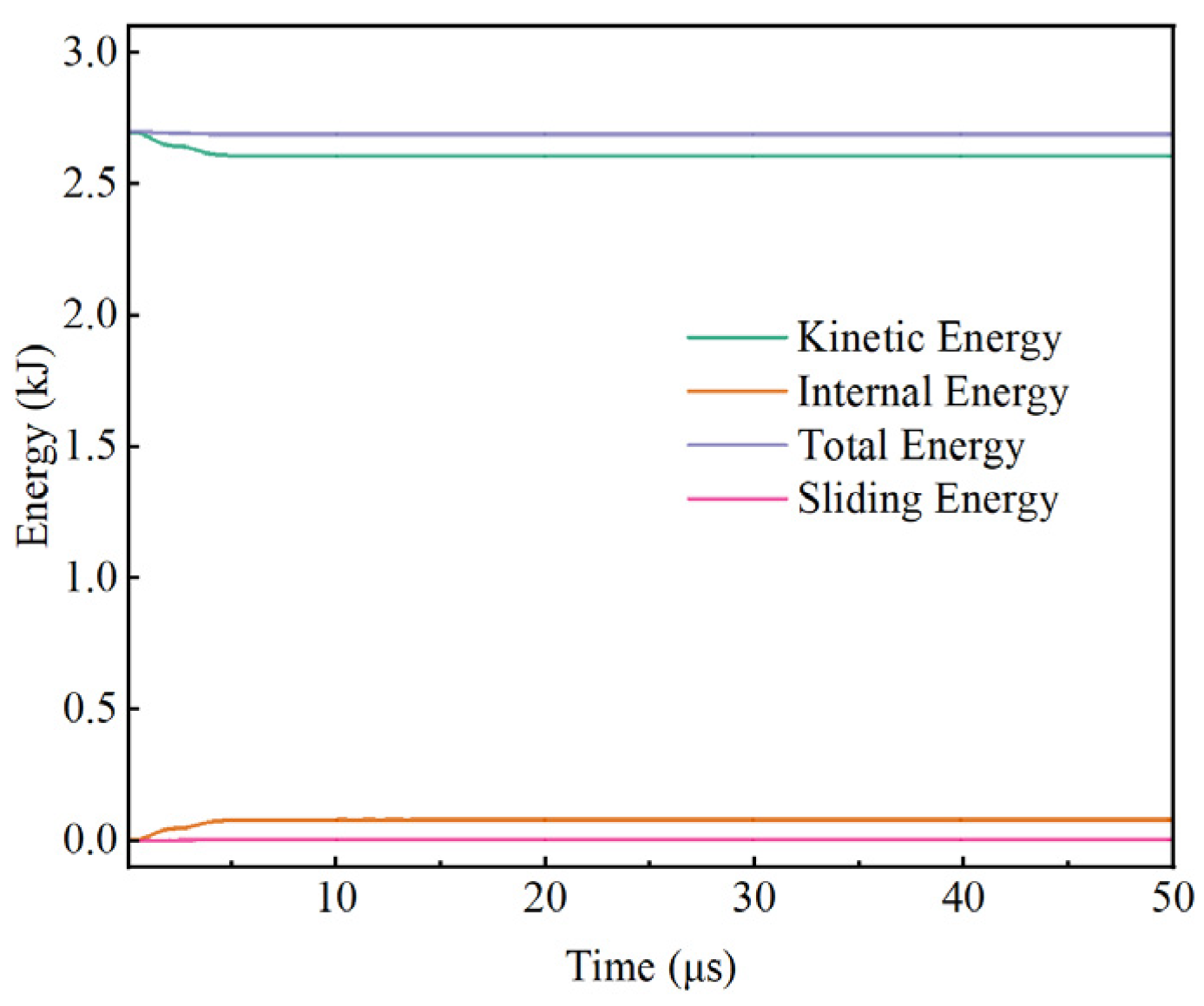
2.1.2. Mesh Converge and Energy Conservation

To verify the grid independence of the finite element model, single-projectile penetration into a target plate (incident velocity Vi = 500 m/s) was analyzed by using three mesh configurations: coarse mesh (1 mm × 1 mm), moderately refined mesh (0.5 mm × 0.5 mm), and finely refined mesh (0.2 mm × 0.2 mm). These models comprised 119,145, 610,272, and 2,622,664 elements, respectively. Under a consistent global loading level of 370 MPa, the same position (15.3 mm from the center of the sphere in the X direction) was selected as the test point. The maximum equivalent stress (von Mises stress) at this test point was extracted from the simulation results, as shown in Figure 4. The stress variation trends at the test point were consistent across all three mesh scales. Notably, the differences between the 0.2 mm and 0.5 mm mesh sizes were minimal. Considering both computational accuracy and efficiency, the 0.5 mm mesh size was ultimately adopted for this study.
The energy change curves from the numerical model are presented in Figure 5. Throughout the simulation, the total energy remains balanced at 2.69 kJ. The variations in internal energy and kinetic energy closely mirror those observed during actual fragment penetration processes. Notably, the sliding energy, which encompasses both the potential energy stored in contact springs and frictional energy, remains virtually zero throughout the process, falling within an acceptable range.

2.1.3. Constitutive Models

In this study, the aircraft thin-walled structure is modeled by using 7075-T6 aluminum alloy, while the fragment is modeled by using 10# steel. The constitutive behavior of the 7075-T6 aluminum alloy is characterized by the Johnson–Cook model.
The Johnson–Cook constitutive model is widely used in impact dynamics and is generally employed to describe metal materials’ strength limits and failure processes under large strain, high strain rates, and elevated temperatures. Unlike conventional plasticity theories, the Johnson–Cook model characterizes material response after impact or penetration by using parameters such as hardening, strain rate effects, and thermal softening [20]. Each of these parameters accumulates effects through multiplication.
σ y = A + B ε n 1 + C ln ε ˙ ε ˙ 0 1 T m ,
where ε is the equivalent plastic strain, ε ˙ is the current strain rate, ε ˙ 0 is the reference strain rate, ε ˙ / ε ˙ 0 is the reference equivalent strain rate, and T* is the relative temperature, which is calculated as follows:
T = T T r T m T r
T represents the local temperature, Tr is the room temperature, and Tm is the material’s melting point. The other five constants are the material physical property constants of the Johnson–Cook model: A is the initial yield stress, B is the hardening constant, K1 is the static yield stress, C is the strain rate constant, n is the hardening exponent, and m is the thermal softening exponent. These can be fitted with the following formulas after determining the data through material testing:
ln ( σ A ) = n ln ε + ln B
σ = K 1 1 + C ln ε ˙ ε ˙ 0
ln σ = m ln T T > > 1
The strain at fracture is given by
ε f = [ D 1 + D 2 e D 3 σ ] [ 1 + D 4 ln ε ˙ ] [ 1 + D 5 T ]
where σ is the stress triaxiality and D1~D5 are the failure parameters.
The Johnson–Cook model determines the yield stress by strain, strain rate, and temperature. The model is composed of three parts, representing material strain hardening, strain rate strengthening, and thermal softening. It comprehensively considers the relationship between rheological stress and strain, strain rate, and temperature, meeting the simulation material requirements under most conditions. Values of these failure parameters for AA7075-T6 were taken from [17,19] and are listed in Table 1.

2.2. Model Validation

2.2.1. Damage Morphology Comparison

To verify the validity of the model, this section compares and validates the simulation results against the experimental data from García-Castillo et al. [17]. The target plate was subjected to two loading conditions: preloaded (51 kN tensile load) and unloaded. The spherical fragment used in the simulation had the same dimensions as in the experiment and hit the target plate perpendicularly at a velocity of 127 m/s. As shown in Figure 6, the damage morphologies obtained from both the experiment and simulation are highly consistent under both preloaded and unloaded conditions. In both cases, the aluminum alloy target plate exhibited petalling deformation along the perimeter of the penetration hole and shear plugging at the impact hole center. The petalling deformation led to significant stress concentration, creating favorable conditions for crack propagation. Specifically, Figure 6a shows that cracks propagated along the stress concentration regions of the petalling under the preloaded condition, which is consistent with the experimental observations.

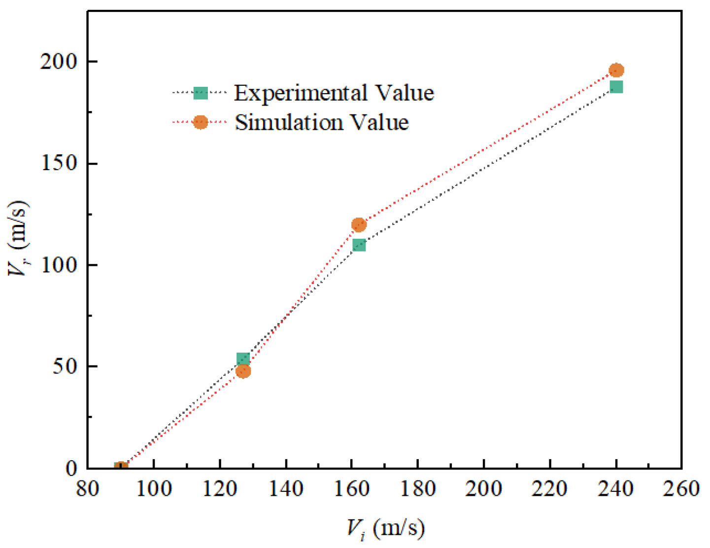
2.2.2. Residual Velocity Comparison

As shown in Figure 7, four sets of incident velocities (Vi) and residual velocities (Vr) of the fragment under the preloaded condition were selected for comparison with the simulation results. Under identical incident velocity conditions, the error in the remaining velocity between the experimental and simulation results was relatively small, with a maximum error of 11%. The residual velocity is a critical parameter that characterizes the energy conversion during projectile penetration. The small error demonstrates that the model can accurately represent the dynamic process of fragment penetration observed in real experiments.

3. Results and Discussion

3.1. Preloaded Level

When multi-fragments are distributed circumferentially, with D = 1d and Vi = 500 m/s as an example, four reference groups were established: unloaded and 370 MPa, 440 MPa, and 458 MPa loading conditions. The damage morphology and stress distribution of the target plate at t = 50 μs are shown in Figure 8. Under all four conditions, the target plate exhibits cumulative damage between impact holes, forming a central puncture hole surrounded by multiple-impact holes. This is accompanied by plug formation due to fragment penetration and plug formation from the failure of connections at the center. In the unloaded condition, cracking at the edges of the holes is more pronounced. As the loading level increases, the number of failed plug units increases, and their volume decreases. The deflection of the target plate under unloaded conditions is 10.9 mm, slightly higher than that under the three loaded conditions (9.6 mm, 9.8 mm, and 9.7 mm). Under unloaded conditions, the maximum stress concentration occurs around the edge of the central hole and is symmetrically distributed. As the loading level increases, the maximum stress distribution extends axially along the Y-axis. Simultaneously, the central hole contracts along the X-axis, and the features of the impact holes become more distinct. It is evident that the loading conditions alter the stress accumulation pattern during the impact process, leading to differences in the damage morphology.
To further investigate the influence of tensile loading on the stress wave propagation and superposition process, Figure 9 illustrates the stress evolution in the target plate from 0~10 μs under two conditions: unloaded and 440 MPa when D = 1d and Vi = 500 m/s. At t = 2 μs, during the initial cratering stage, the contact area between the fragment and the target forms a circular high-stress region due to impact. Under the unloaded condition, shear stress around the impact zone is uniformly distributed radially. In contrast, under tensile loading, weak stress regions form along the stretching direction (X-axis), while strong-stress regions develop perpendicular to this direction. As time progresses from t = 4~6 μs, multiple stress superpositions occur in the central region of the penetration holes, particularly in the inter-hole weak zones. For the unloaded target plate, shear stress expands uniformly along the hole edges; for the loaded target plate, the strong-stress region fans out along the Y-axis, and low-stress areas overlap to form elliptical low-stress regions on both sides. By t = 8~10 μs, the projectile has fully penetrated the target, forming a plug, and the penetration process concludes. At this stage, the edges of the impact holes are primarily subjected to tensile stresses induced by edge tension. Stress concentration causes tensile failure along the weak zones adjacent to the penetration center, ultimately leading to the formation of a central hole and a central plug. Throughout the impact process, the unloaded target plate exhibits a uniform ring-shaped stress distribution, with more pronounced cracking at the edges of the central hole (Figure 8a). Under loaded conditions, the presence of perpendicular high-stress and low-stress regions inhibits the lateral expansion of the central hole compared with the unloaded condition.
The effective plastic deformation contour maps of the target plate at t = 50 μs under the four conditions were extracted, as shown in Figure 10. It can be observed that the plastic deformation near the hole edges is significantly more pronounced in the unloaded condition compared with the loaded conditions. As the loading level increases, the plastic zone area expands in a manner consistent with the stress distribution, primarily extending in a fan-like pattern along the Y direction, with ear-shaped protrusions at the leading edge.
The changes in fragment velocity under different loading conditions are illustrated in Figure 11. The remaining velocities of the fragments under the four loading conditions are as follows: (a) 465.7 m/s; (b) 467.0 m/s; (c) 467.3 m/s; and (d) 467.8 m/s. From 0~6 μs, the target plate primarily undergoes cratering formation due to fragment impact, leading to shear failure. During this initial stage, the fragment velocity changes are consistent across all loading conditions, indicating that the target load has minimal influence on the penetration velocity during this period. From 6~22 μs, as previously analyzed, the plug formation is nearly complete, and the fragment’s velocity reduction is impeded by the tensile failure at the hole edges. As the edge tensile damage intensifies, this impediment gradually decreases, resulting in a slower rate of velocity reduction. During this phase, higher loading levels lead to higher remaining fragment velocity. This is because tensile loading enhances the expansion of tensile failure at the hole edges, as shown in Figure 12. On one hand, tensile loading reduces the target’s resistance to fragment penetration, leading to a slower velocity reduction. On the other hand, it also shortens the interaction time between the fragment and the target, ultimately resulting in higher remaining velocity. Notably, from a macroscopic perspective, the high-speed impact of the fragment on the target is a transient process with a short total contact time. Therefore, the loading level has a limited effect on the final remaining velocity, with the maximum difference (between unloaded and 458 MPa) being only 0.45%.

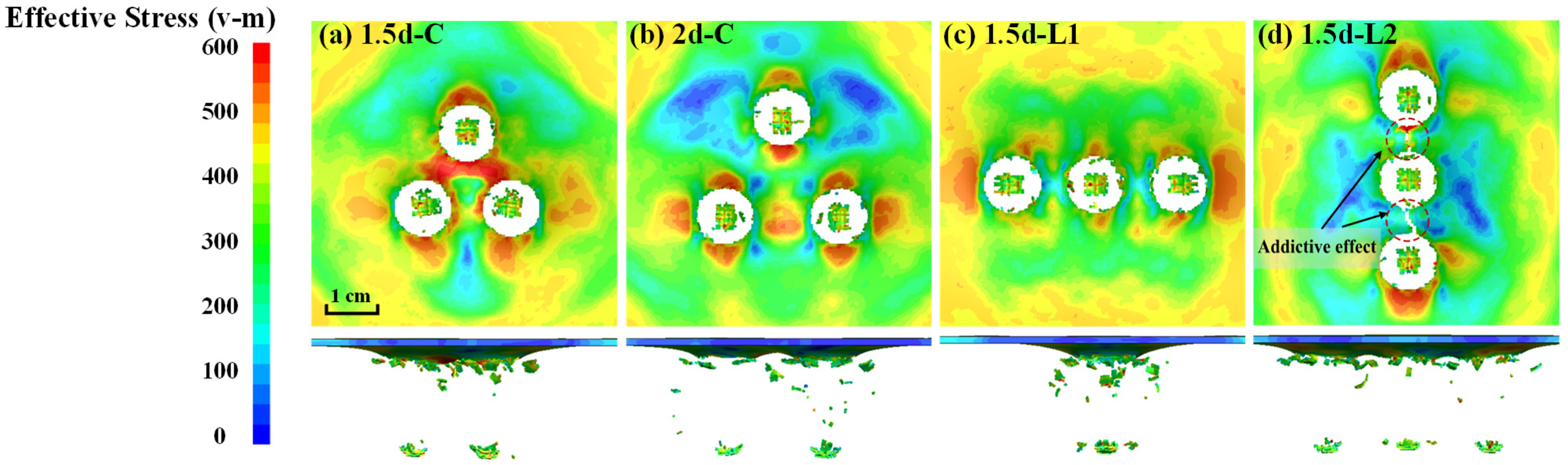
3.2. Fragment Distribution

At a preloading level of 370 MPa and an incident velocity of 500 m/s, different fragment distribution patterns as shown in Figure 3 were considered. The damage morphology and stress distribution of the target plate at t = 50 μs are illustrated in Figure 13. As the hole spacing increases, the stress coupling effect between adjacent holes significantly diminishes, leading to a shift from cumulative damage to independent penetration by multiple fragments. This results in reduced normal deformation of the target plate (Figure 13a,b). When considering the longitudinal distribution of fragments, along the X direction (L1), the low-stress extension zone between adjacent holes experiences minimal stress accumulation, allowing each fragment to maintain independent penetration. In contrast, along the Y direction (L2), the load-bearing area of the target plate is substantially reduced after fragment impact (Figure 13c,d). Under the influence of stress accumulation, the inter-hole region undergoes instantaneous fracture, resulting in an additive effect during multi-fragment penetration (Figure 13d).
In the L2 distribution, the net cross-sectional area of the target plate in the load-bearing direction is significantly reduced due to fragment penetration (Figure 14a). As the loading level increases, yield deformation initiates in the direction of the minimum net cross-sectional area. At higher loading levels, cracks begin to appear in the penetration holes (Figure 14b,c), which, under sustained loading, will eventually lead to the complete failure of the target plate.

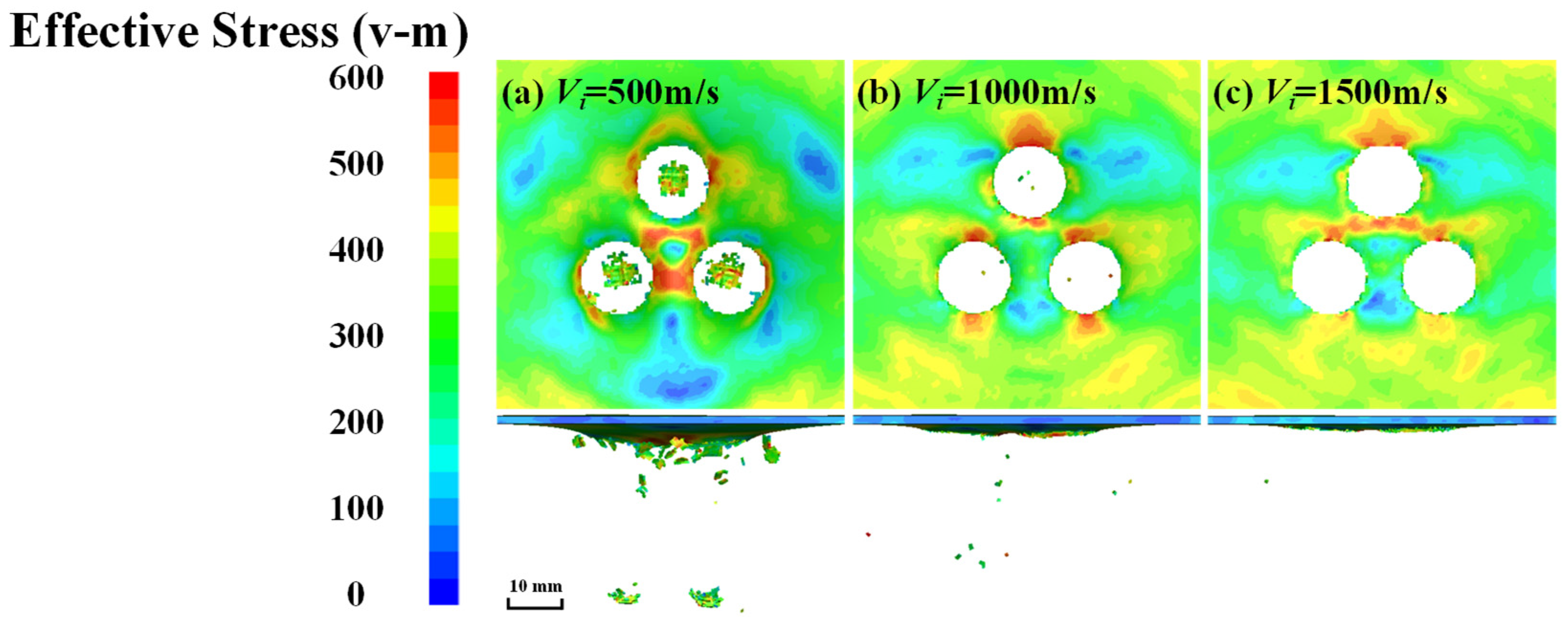
3.3. Fragment Velocity

Under a preloading level of 370 MPa, with fragments distributed in a circular pattern and an inter-distance of 1.5d, the effects of multiple fragments on the target plate were examined at different impact velocities (500 m/s, 1000 m/s, and 1500 m/s). As shown in Figure 15, the damage morphology and stress distribution at t = 70 μs indicate that as the fragment velocity increases, the plastic deformation of the target plate under fragment group impact significantly decreases (Figure 15a,b), and the jamming phenomenon disappears. Due to the intense impact force, the depression formed by fragment penetration rapidly fails, leading to element deletion (Figure 15c). In reality, during high-speed fragment impact, the depression completely shatters into a fine-particle group.
As the fragment velocity increases, the interaction time between the fragment and the target decreases, and the failure mode of the target plate transitions from shear–tension failure to pure shear failure. Consequently, the stress coupling effect between the various penetration holes further diminishes, and the penetration behavior becomes increasingly independent.

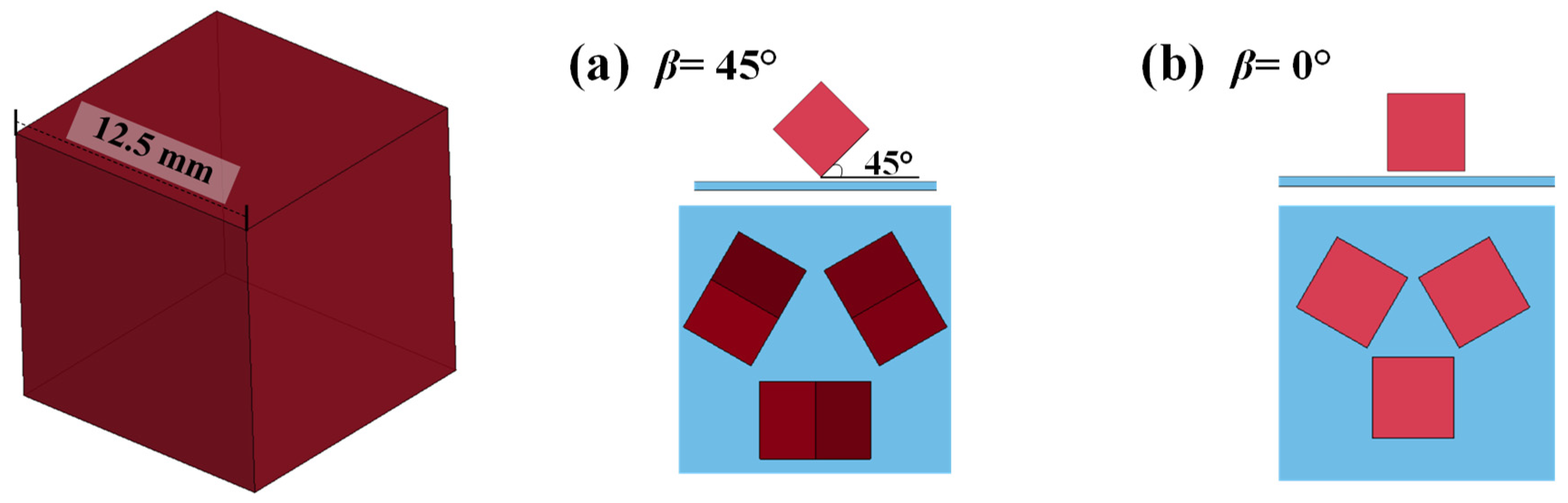
3.4. Fragment Shape and Attitude Angle

Cubic fragments are a common type of prefabricated fragment used in warheads. In order to study the effects of different fragment shapes and the attitude angle β, various multiple-cubic-fragment impact conditions with radial distribution were set up, as shown in Figure 16.
When the fragments penetrate at two different attitude angles, the failure modes of the target plate are distinctly different. At β = 45°, the fragment hits the plate with its sharp end, leading to significant local stress concentration in the target plate, which makes it highly susceptible to crack initiation. Under the continuous penetration and compression by the fragment, tearing occurs along the fragment’s edge. In contrast, at β = 0°, the contact area between the fragment and the target plate is larger, resulting in shear failure along the stress concentration on the fragment’s edge. This leads to extensive plastic deformation and the formation of a large-area plug, as shown in Figure 17.
Under a 370 MPa loading level, with fragments distributed in a circular pattern and an inter-distance of 1.5D, the damage morphology and stress distribution of the target plate at t = 50 μs under three different impact conditions (Vi = 500 m/s) are shown in Figure 18. Under the different impact conditions, the sharp-end fragment exhibits significantly greater destructive potential. The compression and tearing actions of the fragment result in larger broken-hole areas. The tearing edges fracture under the coupled action of multiple fragments, leading to the formation of large-area plug failures. Tearing damage is more likely to initiate cracks at stress concentration points near the endpoints due to the combined effect of tensile loading. In contrast, under plane-end impact conditions, the coupled action mechanism of the shrapnel group resembles that of spherical shrapnel. The stress concentration phenomenon along the edges of the broken holes formed by cubic-shrapnel penetration is more pronounced, making the broken-hole endpoints more susceptible to crack initiation under tensile loading.

4. Conclusions

This paper presents a numerical simulation-based finite element model to investigate the dynamic response of an aluminum alloy thin-walled structure subjected to multiple-fragment penetration under pre-tensile loading, considering the actual scenario of fragment–target interception. The model systematically examines various parameters, including the loading level, and the distribution pattern of the fragments, including velocity, type, and incident conditions. This study elucidates the coupled effects of these parameters on structural failure and destruction, revealing the mechanisms and influence laws of pre-tensioned loading in multiple-projectile penetration. The main conclusions can be summarized as follows:
(1)
Tensile loading alters the propagation pattern of impact stress waves, causing them to spread in a fan shape. The region along the tensile direction experiences weaker stress, while the region perpendicular to the tensile direction experiences stronger stress.
(2)
Tensile loading reduces the resistance of the target plate to fragment penetration, leading to a slower rate of velocity reduction. Additionally, it decreases the interaction time between the fragment and target, resulting in higher residual velocity. However, under high-speed impact conditions, the short contact time limits the influence of the loading level on the final residual velocity.
(3)
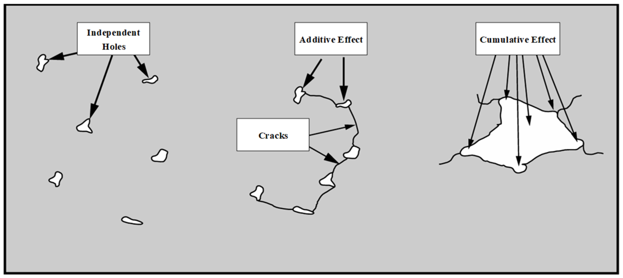
The distribution pattern of fragments (the position of penetration holes) significantly affects the structural response under tensile conditions. Stress superposition perpendicular to the tensile direction is more likely to cause additive damage among projectiles, leading to severe net cross-sectional loss and a significant drop in load-carrying capacity, ultimately resulting in catastrophic failure.
(4)
Fragment velocity significantly influences damage coupling and failure mode transition under pre-tensile loading. As the fragment velocity increases, the stress coupling effect between the various penetration holes further diminishes, and the penetration behavior becomes increasingly independent.
(5)
Fragment geometry significantly affects target damage under pre-tensile loading. Spherical fragments cause symmetric shear plugging with uniform stress, while sharp-edged cubic fragments (e.g., β = 45°) induce localized stress concentrations, promoting crack initiation and tearing. Flat-ended cubic fragments (β = 0°) generate larger shear plugs via extensive plastic deformation. Pre-tension amplifies the following effects: sharp fragments exhibit enhanced tensile crack propagation, and flat fragments show increased perpendicular plastic deformation. Geometric variations thus modulate damage mechanisms.
Essentially, the coupled damage effects of multiple fragments stem from stress accumulation. Variations in projectile parameters, target material properties, thickness, and boundary conditions all influence the transmission and accumulation of stress waves, which are exacerbated by tensile loading. This study provides a systematic analysis of this mechanism in the context of aircraft structures subjected to projectile penetration during maneuvering. However, actual aircraft loading and structural configurations are much more complex, and further research integrating experimental validation and multi-physics simulations is needed to address variable dynamic preloads, composite materials, and realistic structural complexities. The research findings can serve as valuable references for damage-tolerant design optimization in aircraft structures.

Author Contributions

Conceptualization, Y.W. and T.Z.; methodology, Y.W.; software, Y.W.; validation, H.Z. and Y.H.; formal analysis, Y.W.; investigation, Y.W.; resources, T.Z.; data curation, L.M.; writing—original draft preparation, Y.W.; writing—review and editing, A.R.; visualization, T.Z. All authors have read and agreed to the published version of the manuscript.

Funding

This research study received no external funding.

Data Availability Statement

Due to the nature of this research study, the participants of this study did not agree for their data to be shared publicly, so supporting data are not available.

Conflicts of Interest

The authors declare no conflicts of interest.

References

  1. Pywell, M.; MacDiarmid, I. Design Aspects of Aircraft Vulnerability. In Encyclopedia of Aerospace Engineering; Wiley: Hoboken, NJ, USA, 2010. [Google Scholar]
  2. Dou, M.; Fan, Z.; Li, L.; Wang, X.; Li, L. Experimental and numerical investigation on high-velocity hail impact response of TC4 titanium alloy plates. Thin-Walled Struct. 2024, 197, 111582. [Google Scholar] [CrossRef]
  3. Wang, Y.; Zhang, T.; He, Y.; Ye, J.; Zhang, H.; Fan, X. Analysis of Damage of Typical Composite/Metal Connecting Structure in Aircraft under the Influences of High-Velocity Fragments. Appl. Sci. 2022, 12, 9268. [Google Scholar] [CrossRef]
  4. Wang, Y.-T.; He, Y.-T.; Zhang, T.; Fan, X.-H.; Zhang, T.-Y. Damage analysis of typical structures of aircraft under high-velocity fragments impact. Alex. Eng. J. 2023, 62, 431–443. [Google Scholar] [CrossRef]
  5. Chen, T.; Chong, J.; Changxiao, Z.; Xin, W.; Yuting, W. Mechanism of polyurea in protecting liquid-filled square aluminum tube from the impact of high-velocity projectile. Thin-Walled Struct. 2023, 182, 110315. [Google Scholar]
  6. Qian, L.; Qu, M. Study on terminal effects of dense fragment cluster impact on armor plate. Part II: Numerical simulations. Int. J. Impact Eng. 2005, 31, 769–780. [Google Scholar] [CrossRef]
  7. Qian, L.; Qu, M.; Feng, G. Study on terminal effects of dense fragment cluster impact on armor plate. Part I: Analytical model. Int. J. Impact Eng. 2005, 31, 755–767. [Google Scholar] [CrossRef]
  8. Shen, Y.; Wang, Y.; Du, S.; Yang, Z.; Cheng, H.; Wang, F. Effects of the adhesive layer on the multi-hit ballistic performance of ceramic/metal composite armors. J. Mater. Res. Technol. 2021, 13, 1496–1508. [Google Scholar] [CrossRef]
  9. Qiang, L.; Zhang, R.; Zhao, C.; Ren, J.; Ni, C.; Zhenyu, Z.; Lu, T. Multiple ballistic impacts of thin metallic plates: Numerical simulation. ARCHIVE Proc. Inst. Mech. Eng. Part C J. Mech. Eng. Sci. 2022, 236, 7962–7973. [Google Scholar] [CrossRef]
  10. Paredes-Gordillo, M.A.; Iváñez, I.; García-Castillo, S.K. Numerical study of the simultaneous multiple impact phenomenon on CFRP plates. Compos. Struct. 2023, 320, 117194. [Google Scholar] [CrossRef]
  11. Göde, E.; Teoman, A.; Çetin, B.; Tonbul, K.; Davut, K.; Kuşhan, M.C. An experimental study on the ballistic performance of ultra-high hardness armor steel (Armox 600T) against 7.62 mm × 51 M61 AP projectile in the multi-hit condition. Eng. Sci. Technol. Int. J. 2023, 38, 101337. [Google Scholar] [CrossRef]
  12. Ball, R.E. The Fundamentals of Aircraft Combat Survivability Analysis and Design; American Institute of Aeronautics and Astronautics: Reston, VA, USA, 2003. [Google Scholar]
  13. Rathnasabapathy, M.; Mouritz, A.P.; Orifici, A.C. Finite element modelling of the impact response of fibre metal laminates under tension preloading. Compos. Part A Appl. Sci. Manuf. 2022, 157, 106930. [Google Scholar] [CrossRef]
  14. Kumar, V.V.; Rajendran, S.; Balaganesan, G.; Surendran, S.; Selvan, A.; Ramakrishna, S. High velocity impact behavior of Hybrid composite under hydrostatic preload. J. Compos. Mater. 2022, 56, 3769–3779. [Google Scholar] [CrossRef]
  15. Xu, S.; Li, Y.; Zhou, S.; Jiang, X.; Xie, W.; Zhang, W. Ballistic performance and damage analysis of CFRP laminates under uniaxial pretension and precompression. Int. J. Impact Eng. 2023, 178, 104620. [Google Scholar] [CrossRef]
  16. Gürgen, S. Impact Behavior of Preloaded Aluminum Plates at Oblique Conditions. Arab. J. Sci. Eng. 2019, 44, 1649–1656. [Google Scholar] [CrossRef]
  17. García-Castillo, S.K.; Sánchez-Sáez, S.; Barbero, E. Behaviour of uniaxially preloaded aluminium plates subjected to high-velocity impact. Mech. Res. Commun. 2011, 38, 404–407. [Google Scholar] [CrossRef]
  18. Zhou, B.; Liu, B.; Zhang, S. The Advancement of 7XXX Series Aluminum Alloys for Aircraft Structures: A Review. Metals 2021, 11, 718. [Google Scholar] [CrossRef]
  19. Brar, N.S.; Joshi, V.S.; Harris, B.W. Constitutive Model Constants for Al7075-T651 and Al7075-T6. AIP Conf. Proc. 2009, 1195, 945–948. [Google Scholar]
  20. Johnson, G.R.; Cook, W.H. Fracture characteristics of three metals subjected to various strains, strain rates, temperatures and pressures. Eng. Fract. Mech. 1985, 21, 31–48. [Google Scholar] [CrossRef]
Figure 1. Multiple-hit damage effects [12].
Aerospace 12 00353 g001
Figure 2. Finite element model setup.
Aerospace 12 00353 g002
Figure 3. Model loading level and fragment distribution setup.
Aerospace 12 00353 g003
Figure 4. Mesh convergence test.
Aerospace 12 00353 g004
Figure 5. Model energy variation.
Aerospace 12 00353 g005
Figure 6. Deformations and stress distribution on targets ((a) preloaded condition and (b) unloaded condition).
Aerospace 12 00353 g006
Figure 7. Experimental and simulation residual velocity comparison.
Aerospace 12 00353 g007
Figure 8. Damage morphology and stress distribution at t = 50 μs under diverse loads.
Aerospace 12 00353 g008
Figure 9. Propagation of stress waves.
Aerospace 12 00353 g009
Figure 10. Effective plastic strain iso-surface.
Aerospace 12 00353 g010
Figure 11. Time history of fragment velocity change under diverse loads.
Aerospace 12 00353 g011
Figure 12. Force schematic diagram of hole edge under diverse loading conditions.
Aerospace 12 00353 g012
Figure 13. Damage morphology and stress distribution at t = 50 μs in diverse fragment distributions.
Aerospace 12 00353 g013
Figure 14. Damage morphology of L2 distribution at t = 70 μs under diverse loads.
Aerospace 12 00353 g014
Figure 15. Damage morphology of target plate at diverse fragment speeds.
Aerospace 12 00353 g015
Figure 16. Schematic diagram of cubic-fragment incident conditions.
Aerospace 12 00353 g016
Figure 17. Failure modes of target plate at different attitude angles.
Aerospace 12 00353 g017
Figure 18. Damage morphology of target plate under different types of fragments and attitude angles.
Aerospace 12 00353 g018
Table 1. AA7075T6 Johnson–Cook model parameters [17,19].
Johnson–Cook Model ParametersSymbol7075-T6
Density (kg/m3)R02770
Poisson’s ratioPR0.33
Young’s modulus (GPa)E71.7
Static yield limit (MPa)A448
Strain hardening modulusB343
Strain hardening exponentn0.41
Thermal softening exponentm1.0
Strain rate coefficientC0.0015
Failure parameter D1D10.13
Failure parameter D2D20.13
Failure parameter D3D3−1.5
Failure parameter D4D40.011
Failure parameter D5D51.099
Disclaimer/Publisher’s Note: The statements, opinions and data contained in all publications are solely those of the individual author(s) and contributor(s) and not of MDPI and/or the editor(s). MDPI and/or the editor(s) disclaim responsibility for any injury to people or property resulting from any ideas, methods, instructions or products referred to in the content.

