5.1. Verification of the Proposed ARADO Method
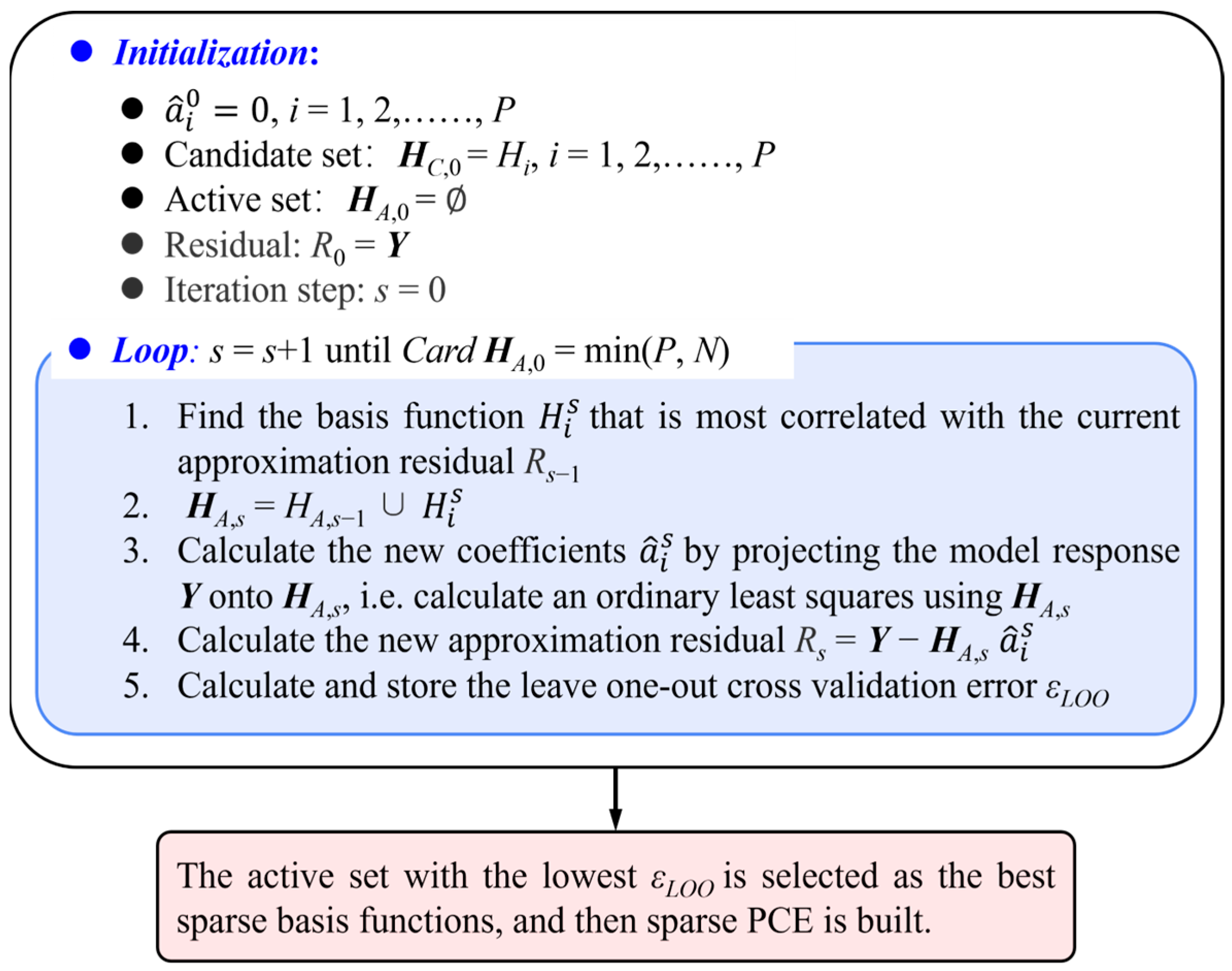
For the optimization problem described in Equation (19), the proposed ARADO method is employed for optimization. Prior to adaptive optimizations, an initial NGPR model with the training sample size set at Ninitial = 40 is constructed. Considering the uniformity of initial training samples, the low-discrepancy sequence sampling method is used. For each sample for training the NGPR model, the proposed sparse PCE is applied twice for aerodynamic UQs at the third polynomial order, yielding μω and σω at two operating incidences, α = −8° and 9°. This means that four CFDs are needed per single UQ, and the total number of CFDs for twice UQs, NUQ, is 8.
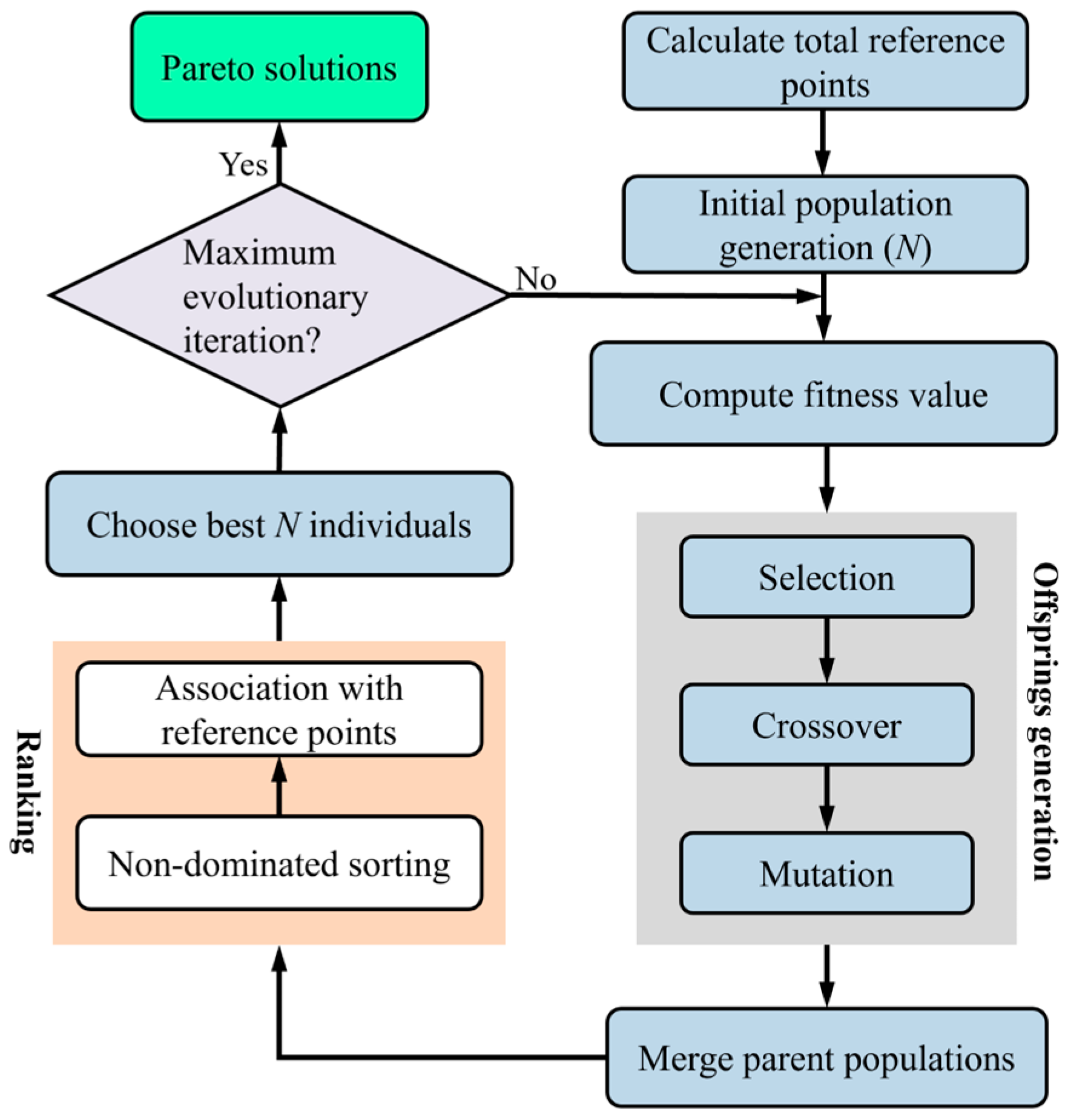
In addition, the parameters for the NSGA-III algorithm are set as follows: population size of 20, evolution generations of 1000, crossover rate of 0.9, and mutation rate of 0.1. Consequently, for each external iteration step of the optimization process, a Pareto-optimal solution set of size Nadaptive = 20 is obtained. The convergence threshold ε0 for the adaptive optimization is set at 1%.
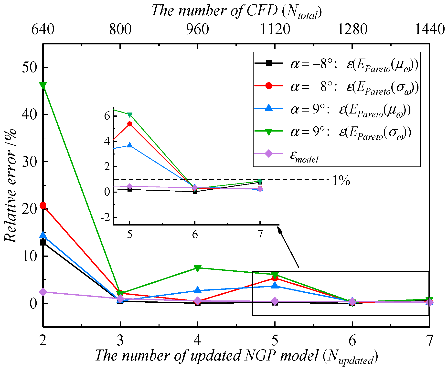
Figure 13 illustrates the external iteration process of the ARADO method. The figure reveals that the ARADO conducts a total of seven external iterations. After the seventh iterative step, the relative error
εmodel remains within 1% across two consecutive iterative steps, which is below the specified convergence threshold
ε0. This outcome confirms the accuracy of the constructed stochastic surrogate model in the vicinity of the Pareto-optimal solutions. Furthermore, it demonstrates that for
α = −8° and 9°, both
ε(
EPareto(
μω)) and
ε(
EPareto(
σω)) are below the threshold of 1% in the sixth and seventh iterations, thereby meeting the prescribed iterative convergence criteria.
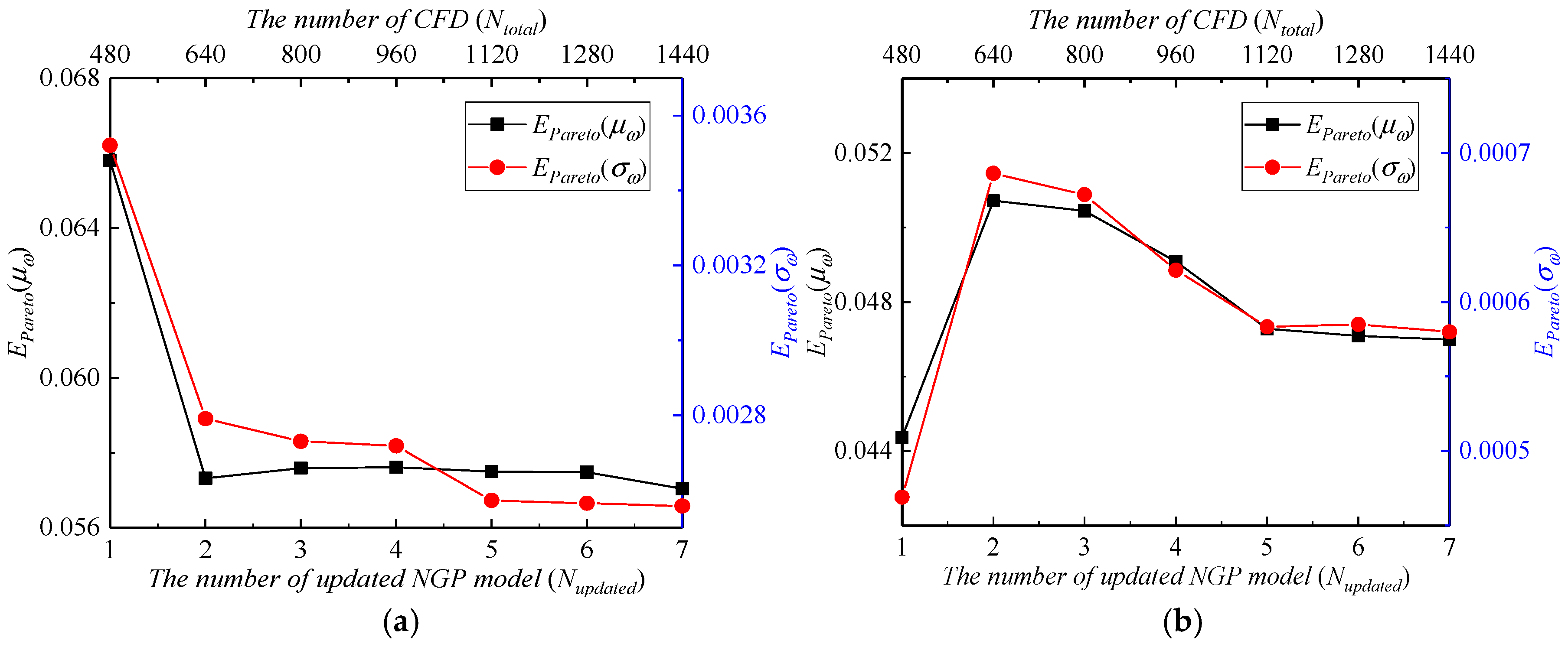
The variations of
EPareto(
μω) and
EPareto(
σω) with the number of external iteration steps are depicted in
Figure 14. When
Nupdated ≥ 5, the
EPareto(
μω) and
EPareto(
σω) for the two aforementioned operating incidences essentially stabilize, affirming the convergence of ARADO. The mean values
EPareto(
μω) and
EPareto(
σω) can reflect the overall level of Pareto. The ARADO method developed in this study yields
EPareto(
μω) and
EPareto(
σω) of 0.057046 and 0.002558, respectively, for
α = −8°, and 0.046993 and 0.00057, respectively, for
α = 9°. In terms of computational expenses, the entire aerodynamic robustness optimization required a total of 1440 CFD evaluations.
To highlight the superiority of the proposed ARADO method, a comparative optimization study was conducted with the SM-RADO method described in
Section 2.2. In SM-RADO, the stochastic surrogate model and optimization algorithm also utilize the NGPR model and NSGA-III, with the NSGA-III parameters set as follows: a population size of 20, 1000 generations, crossover rate of 0.9, and mutation rate of 0.1. Four NGPR models are directly constructed using
Nt = 100, 200, 300, and 500 training samples obtained from low-discrepancy sequences. Subsequently, NSGA-III is invoked for optimization with each model, followed by an analysis of the optimization results.
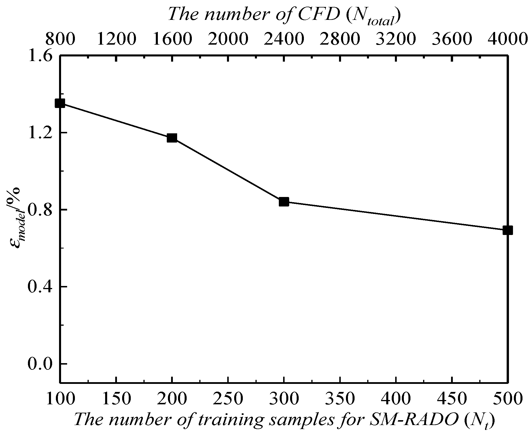
Figure 15 and
Figure 16 depict the variations of SM-RADO results with the number of training samples
Nt.
As shown in
Figure 15, the relative error
εmodel decreases with increasing
Nt. When
Nt = 500, the
εmodel for SM-RADO is approximately 0.69%. However, as shown in
Figure 13, the
εmodel achieved by the developed ARADO method is only 0.25%, which is lower than that obtained by SM-RADO. This further underscores the precision of the stochastic surrogate model constructed by ARADO in the vicinity of the Pareto optimal solutions.
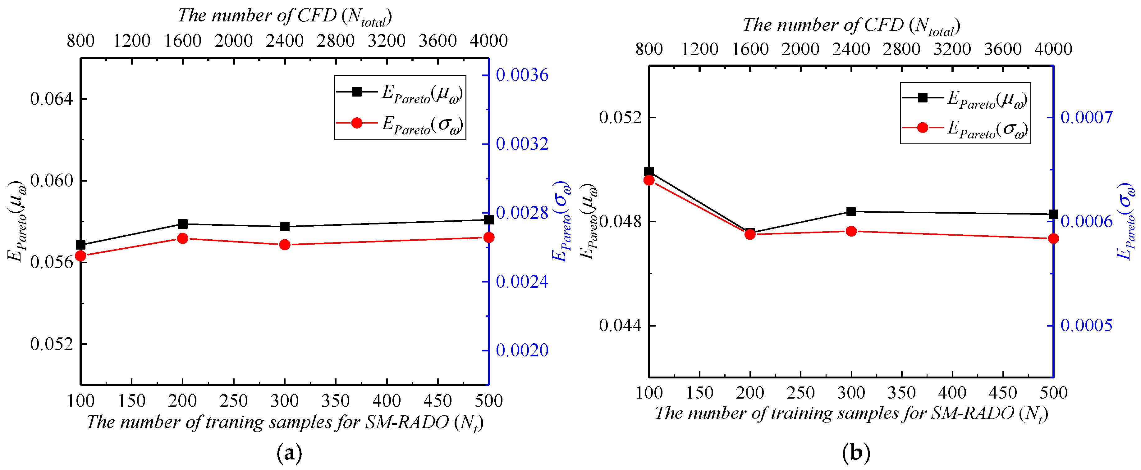
In
Figure 16, after
Nt ≥ 300,
EPareto(
μω) and
EPareto(
σω) exhibit minimal changes, indicating a convergence towards the overall level of Pareto-optimal solutions. At
Nt = 300,
EPareto(
μω) and
EPareto(
σω) are 0.057752 and 0.002616, respectively, for
α = −8°, and 0.048388 and 0.000591, respectively, for
α = 9°, with a total of 2400 CFD evaluations performed for the robust optimization. When
Nt = 500,
EPareto(
μω) and
EPareto(
σω) are 0.058088 and 0.002658 for
α = −8°, and 0.048283 and 0.000584 for
α = 9°, requiring 4000 CFD evaluations for the entire robust optimization.
Table 4 compares the
EPareto(
μω) and
EPareto(
σω) values obtained by the SM-RADO and ARADO approaches. For SM-RADO with
Nt = 100,
EPareto(
μω) and
EPareto(
σω) at
α = −8° are slightly lower than that for ARADO, but significantly higher at
α = 9°. However, for SM-RADO with
Nt = 200, 300, and 500,
EPareto(
μω) and
EPareto(
σω) are notably higher than that for ARADO, at both
α = −8° and 9°. Consequently, the overall level of the Pareto-optimal solutions obtained by ARADO is significantly superior to that obtained by SM-RADO.
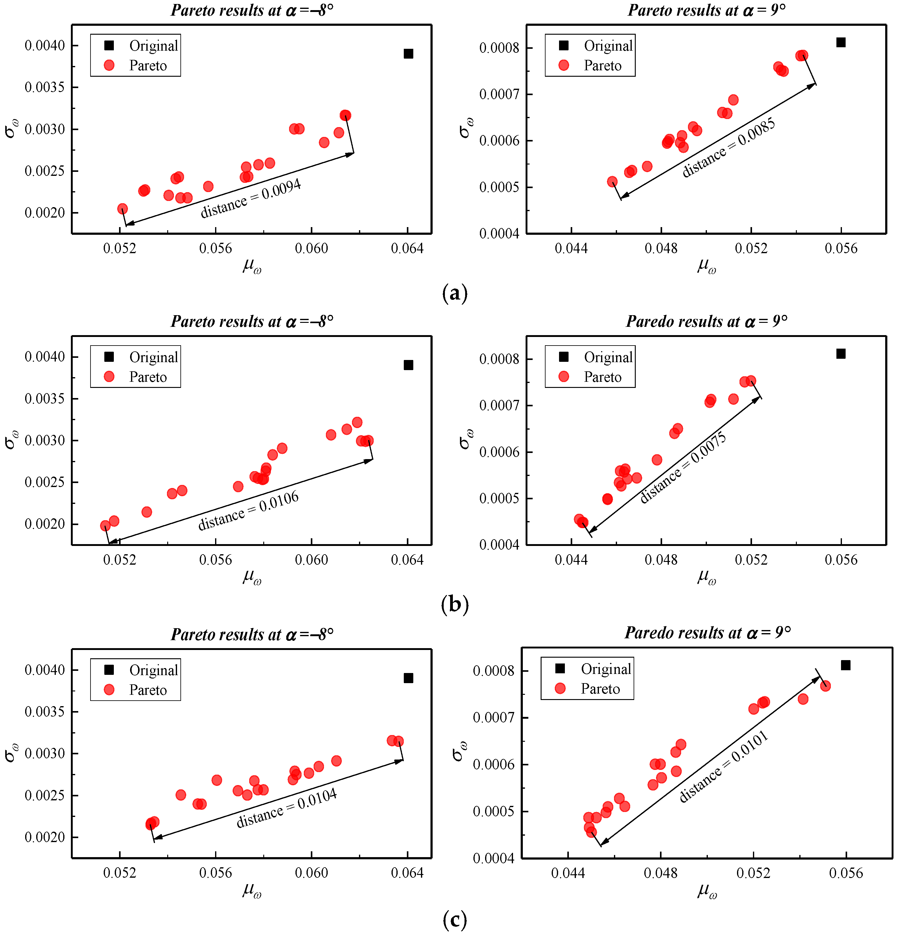
Figure 17 compares the distribution of the Pareto-optimal solutions obtained by M-RADO and ARADO. The optimal solutions obtained by ARADO not only deviate further from the global aerodynamic losses of the original airfoil shape, but are also more concentrated. This suggests that ARADO is more effective in balancing competing optimization objectives, leading to optimization results that are more closely centered around the mean level. From
Table 4 and
Figure 17, it is clear that the quality of the optimization results achieved by ARADO are notably superior to that of SM-RADO.
Table 4 also presents a comparison of the computational efficiency between SM-RADO and ARADO. It is evident that only the SM-RODO with
Nt = 100 requires fewer CFD calculations than ARADO. However, it derived from
Table 4 and
Figure 17 that the optimization quality of ARADO is significantly superior to that of M-RADO. Therefore, the ARADO method developed can achieve better robust optimization results more quickly.
5.2. Discussion of Optimization Results
As indicated in
Figure 13 and
Figure 14, the optimization converged after seven adaptive external iterations.
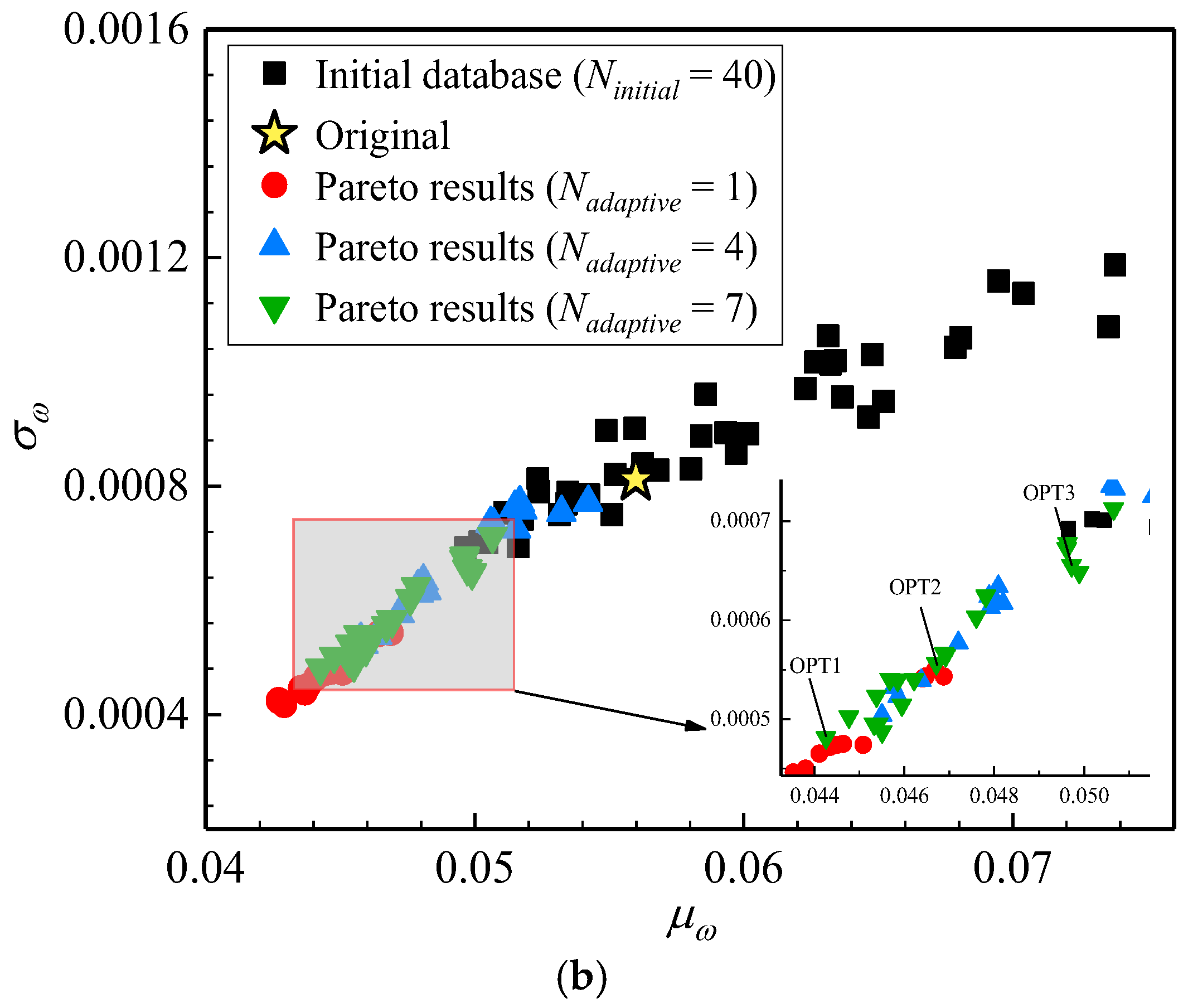
Figure 18 illustrates the variations of the Pareto-optimal solutions with
Nadaptive. As ARADO converges, the Pareto set ultimately demonstrates improved robustness in
ω for both
α = −8° and 9°. To further discuss the final optimization results, three representative optimized airfoils were selected for aerodynamic robustness analysis, denoted as OPT1, OPT2, and OPT3 in
Figure 18.
Figure 19 displays the geometric shapes of the original and three optimized airfoils.
Table 5 showcases the values of
μω and
σω for the original airfoil and three optimized airfoils at
α = −8°. When compared to the original design, OPT1, OPT2, and OPT3 demonstrate reductions in
μω of 4.40%, 12.18%, and 16.57%, respectively. Additionally, the standard deviations
σω for the three optimized airfoils decrease by 22.56%, 37.69%, and 44.10%.
Table 6 presents their
μω and
σω at
α = 9°. Relative to the original design, the
μω values for the three optimized airfoils decrease by 20.95%, 16.57%, and 11.20%, while the corresponding reductions in
σω are 40.76%, 31.53%, and 19.34%, respectively.
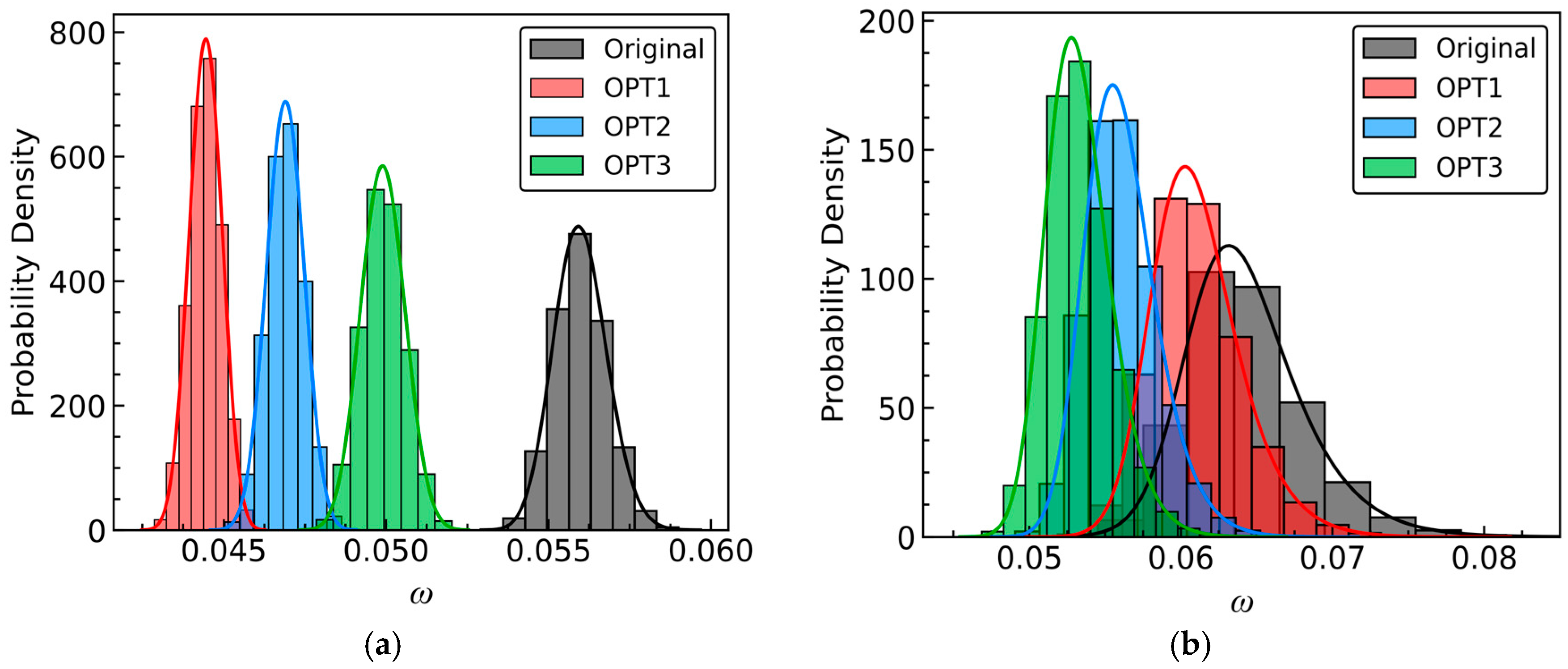
The probability density function (PDF) is a crucial metric for assessing the robustness of aerodynamic performance.
Figure 20 illustrates the PDF of
ω for both the original and optimized blades. The original design exhibits the widest distribution, indicating a higher level of uncertainty or dispersion in
ω. In contrast, the distributions of the three optimized blades are narrower and more peaked, with an overall shift towards lower values. It suggests that under stochastic perturbations in the inflow
Ma, the optimized blades demonstrate reduced variability in
ω while also achieving a decrease in average aerodynamic loss. A comparison of the PDFs for the three optimized blades reveals the following trends: at
α = −8°, the mean levels and dispersions for OPT1, OPT2, and OPT3 decrease successively. Conversely, at
α = 9°, those levels for OPT1, OPT2, and OPT3 increase progressively.
By the analysis of
Table 5 and
Table 6, as well as
Figure 20, it can be deduced that the optimized compressor airfoils obtained by the proposed ARADO significantly enhance the robustness of aerodynamic losses at
α = −8° and
α = 9°. At
α = −8°, the incremental improvements in aerodynamic loss robustness for OPT1, OPT2, and OPT3 decrease successively. Similarly, at
α = 9°, the enhancements in the robustness for OPT1, OPT2, and OPT3 decrease successively.
To confirm that the optimized blades also enhance the robustness of the diffusion capability,
Table 7 provides
and
at α = −8° for the original and three optimized blades. Compared to the original, OPT1, OPT2, and OPT3 show respective increases of 3.96%, 9.02%, and 12.55% in
, along with decreases of 36.36%, 64.98%, and 76.90% in
.
Table 8 presents the statistical moments at
α = 9°. In comparison to the original,
for the three optimized blades increased by 2.96%, 2.14%, and 1.44% respectively, while the
increased by 18.38%, 13.86%, and 8.27% respectively.
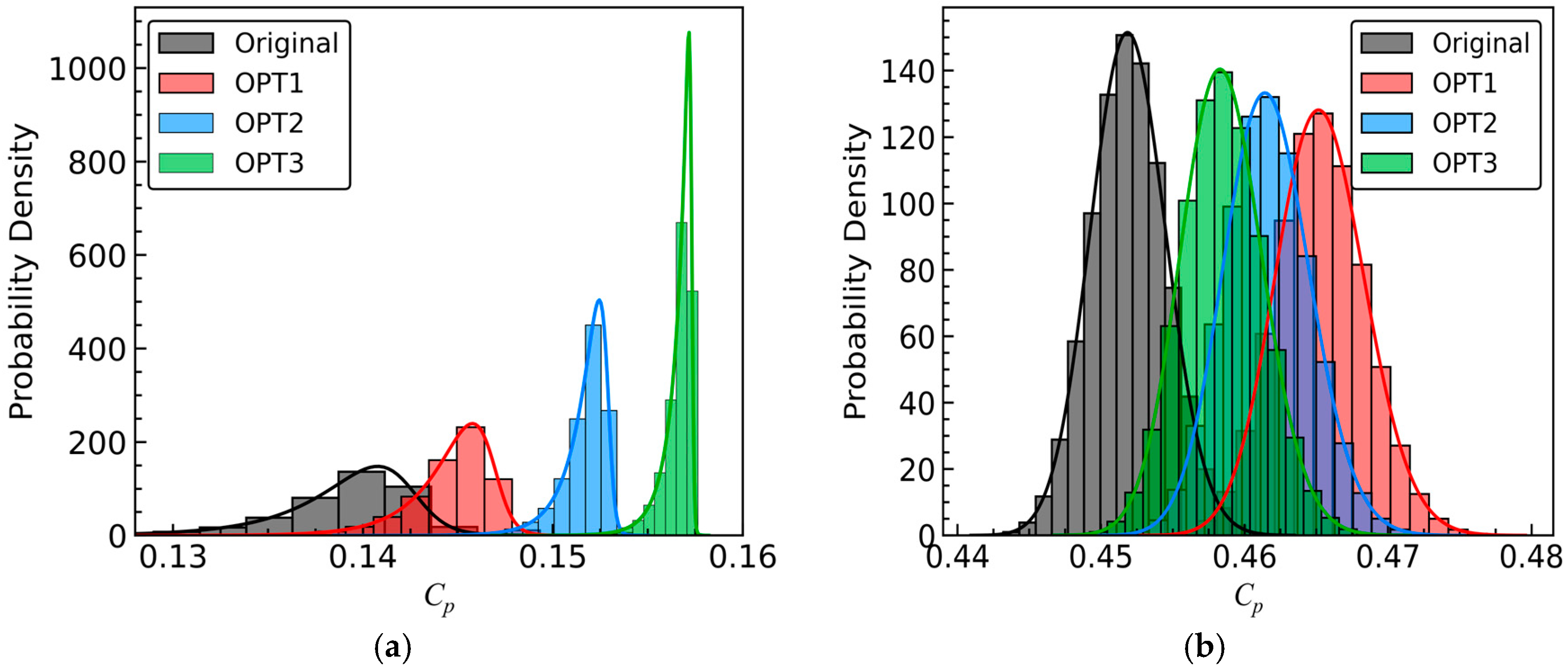
Figure 21 illustrates the PDFs of
Cp for both the original and optimized blades. It indicates that at
α = −8°, the optimized blades exhibit reduced variability in diffusion capability and an increase in average diffusion capability. Comparing the PDFs of the three optimized stator blades reveals that the average levels of diffusion capability for OPT1, OPT2, and OPT3 increase successively, while their dispersions decrease successively.
At
α = 9°, in contrast to the original, the distributions of the optimized blades shift towards higher values, albeit slightly wider and shorter. This suggests an increase in the average diffusion capability, accompanied by a slight increase in the dispersion of diffusion capability. Nonetheless, the probability that their
Cp exceeds the original is over 60%, as depicted in
Figure 21b. Therefore, it is still reasonable to assert that the three optimized stator blades enhance the robustness of diffusion capability at
α = 9°. Comparing the PDFs of the three optimized blades reveals that the average levels for OPT1, OPT2, and OPT3 decrease successively, while the probabilities that
Cp exceeds the original decrease successively.
Through the analysis of
Table 7 and
Table 8, and
Figure 21, it can be concluded that the optimized blades can enhance the robustness of diffusion capability at both
α = −8° and
α = 9°. At
α = −8°, the incremental improvements in the robustness of diffusion capability for OPT1, OPT2, and OPT3 increase successively. Conversely, at
α = 9°, the enhancements in the robustness of diffusion capability decrease successively.
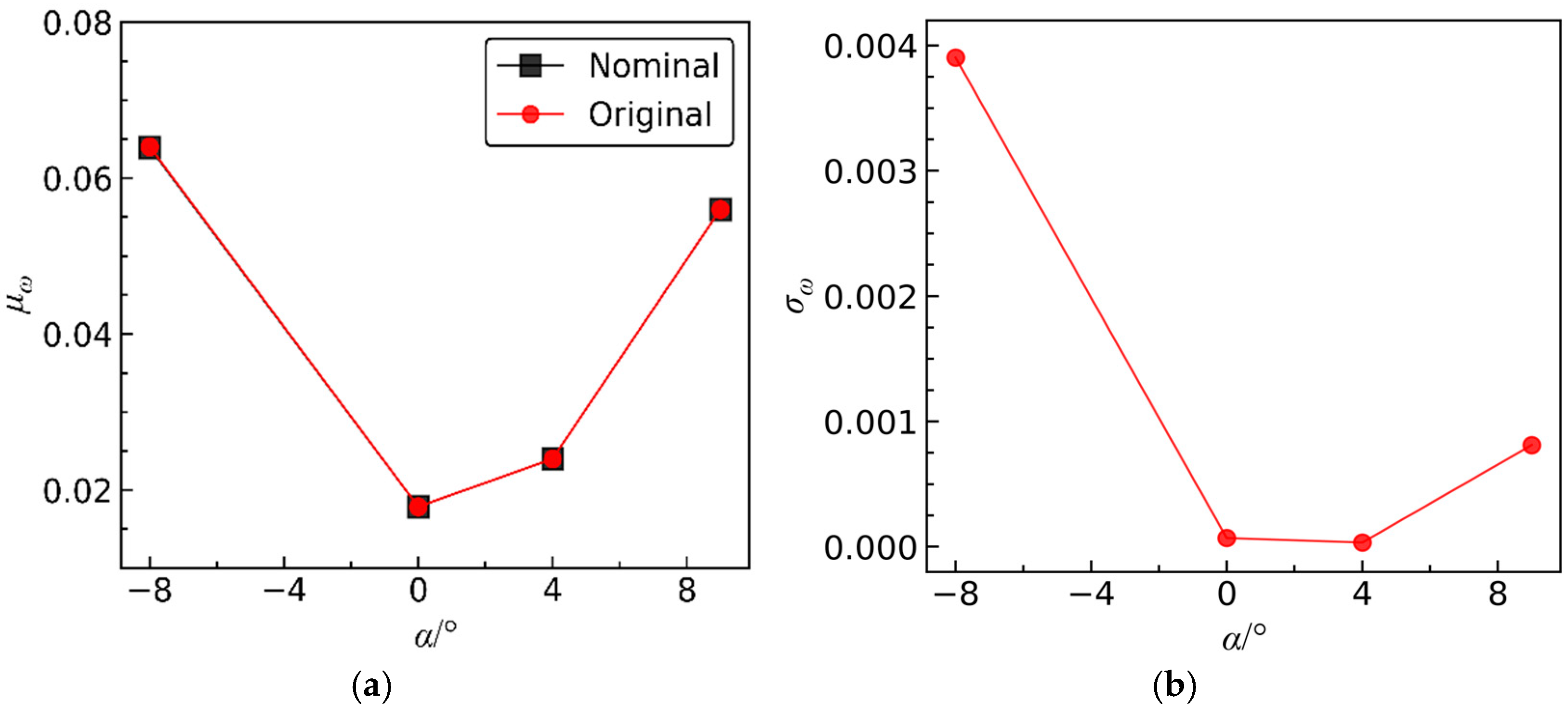
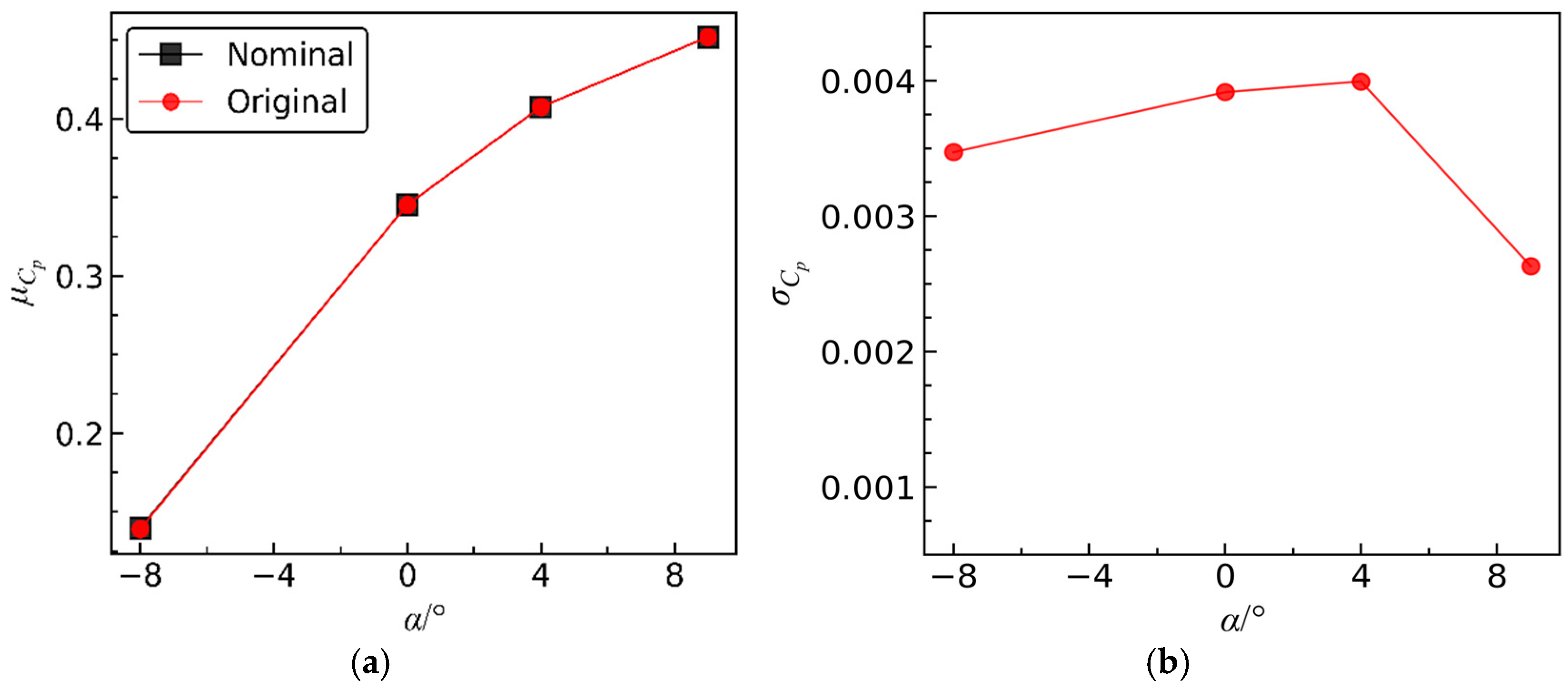
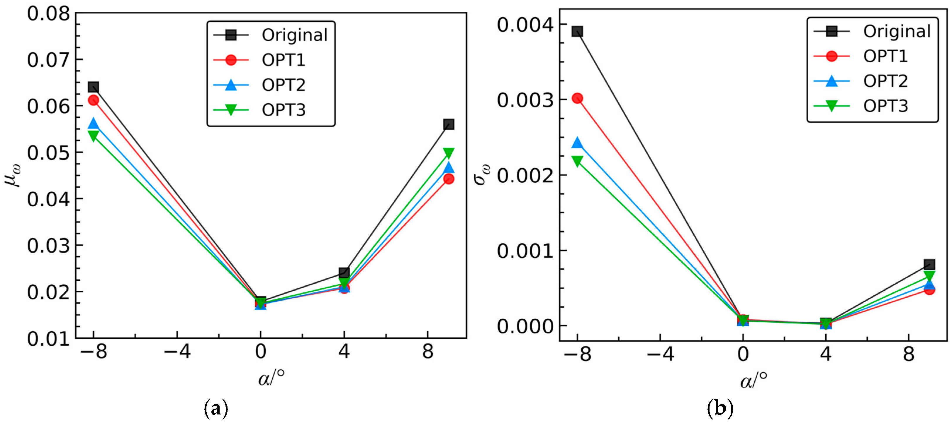
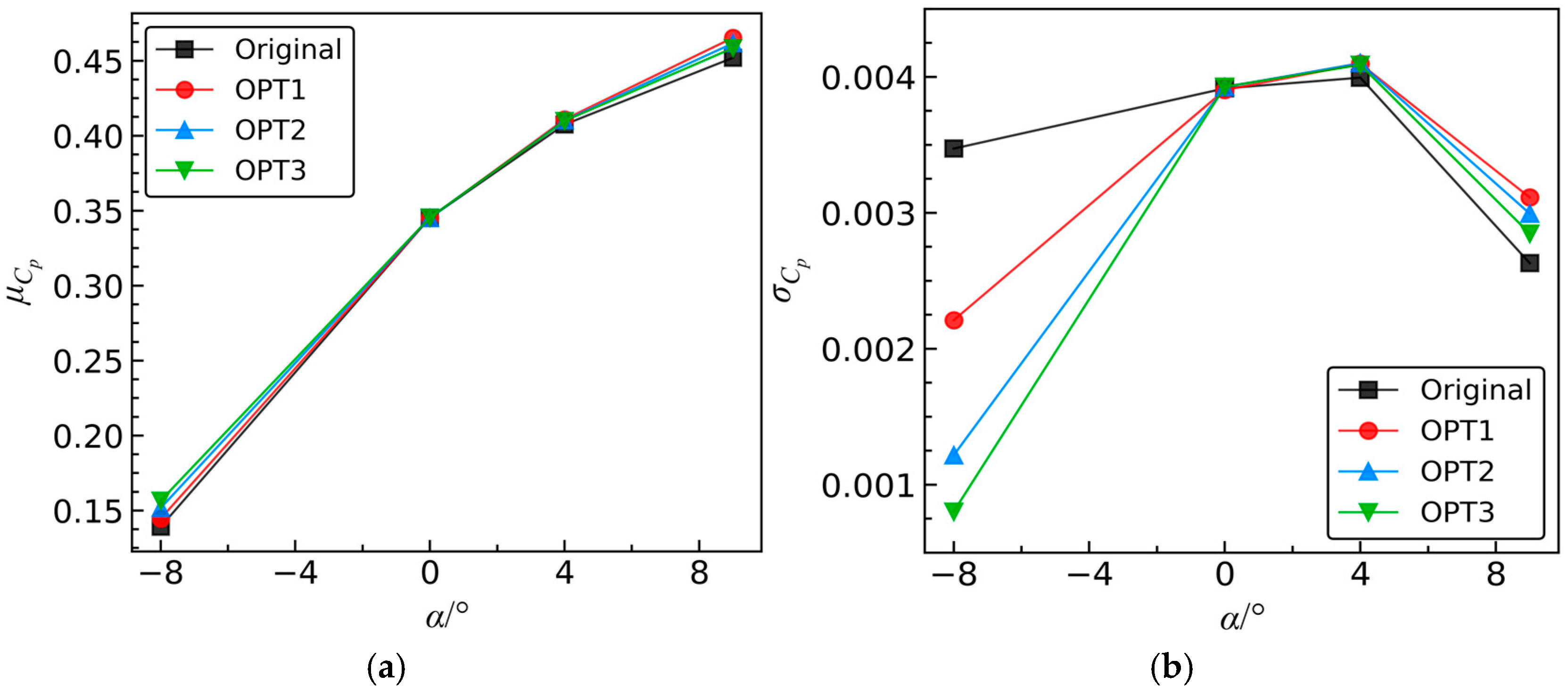
Figure 22 presents the variations of
μω and
σω for the original and optimized blades with the increase in incidence
α, while
Figure 23 illustrates the variations of
and
. At
α = 0° and
α = 4°, the statistical moments of the aerodynamic coefficients exhibit minimal differences compared to the original values. This indicates that the improvement in aerodynamic performance robustness near the design operating incidence is limited. This phenomenon arises because the flow is relatively stable when operating near the design conditions [
30,
44], resulting in less impact from stochastic fluctuations in the inflow
Ma. Therefore, near the operating incidence, the aerodynamic robustness of the optimized blades remains at a consistently good level similar to the original blade. In other words, the optimized results can enhance the robustness of aerodynamic performance across all operating incidences.
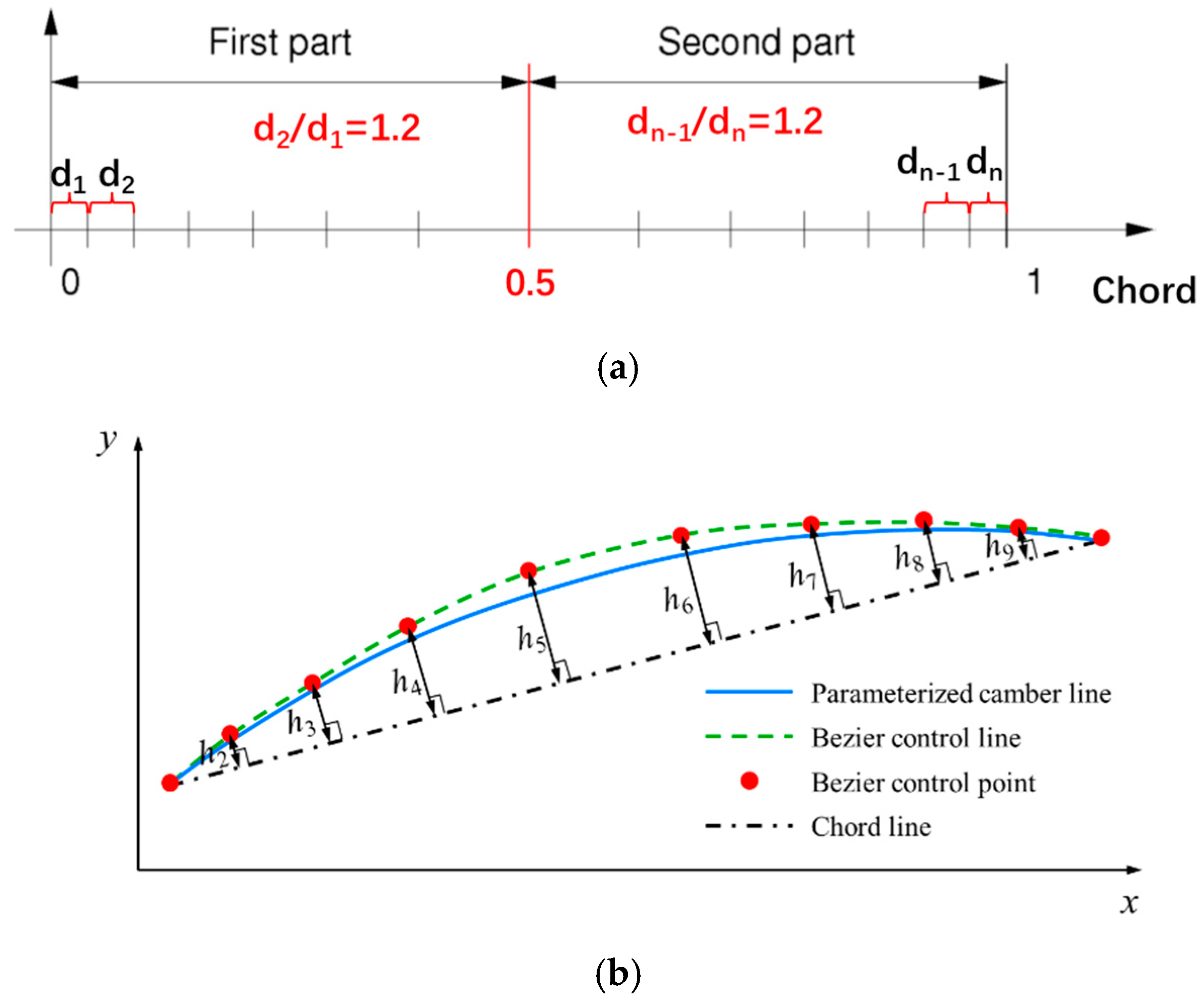
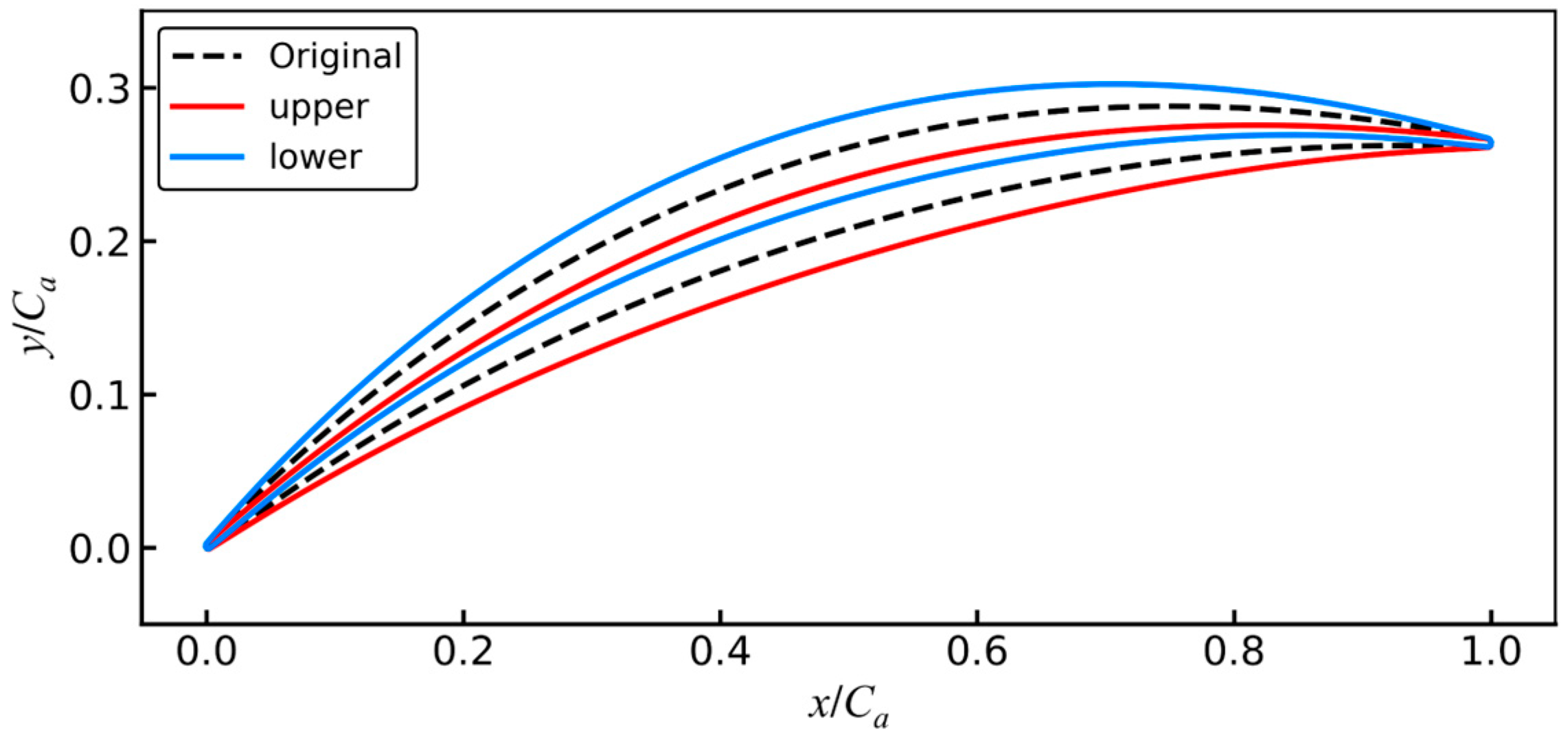
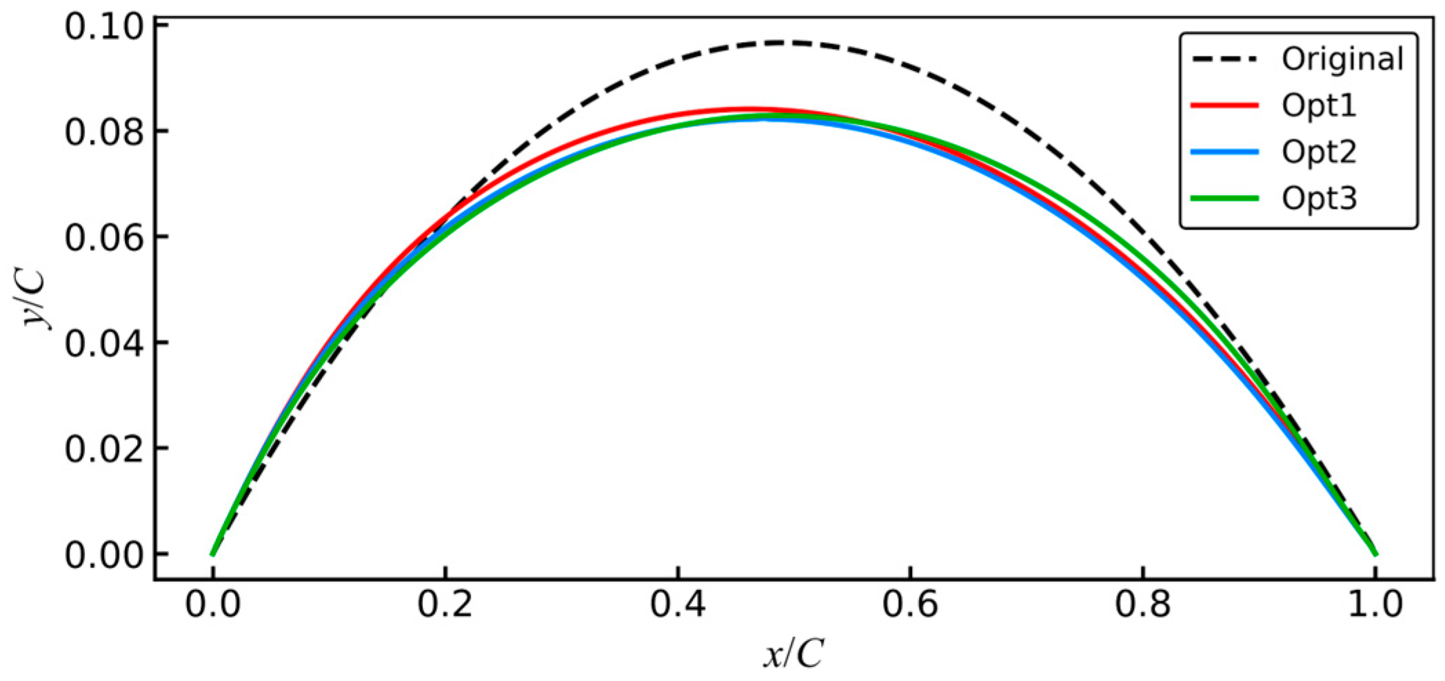
Aerodynamic robustness optimization results can serve as a reference for aerodynamic designers of compressors. The primary design variable changes involve modifications to the camber line. Hence, a comparative analysis of the camber lines was conducted, and the results are depicted in
Figure 24. After optimization, the leading edge angle increases, the position of maximum curvature shifts forward along the chord, the maximum curvature decreases, and the trailing edge angle decreases.
Table 9 further provides the leading edge angle, maximum curvature position, maximum curvature, and trailing edge angle of the three optimized blades. The results indicate that OPT1, OPT2, and OPT3 sequentially increase the leading edge angle, and the maximum curvature position moves backward along the chord length in sequence. In addition, the maximum curvature, as well as the trailing edge angle, first decreases and then increases for OPT1, OPT2, and OPT3.
5.3. Analysis of Flow Field
In the context of OPT1, OPT2, and OPT3, OPT2 stands out as a compromise solution that enhances aerodynamic robustness at both α = −8° and α = 9°. Therefore, OPT2 is focused on as a case study to elucidate the flow mechanisms that optimization solutions improve aerodynamic robustness.
Initially, the mechanism for improving aerodynamic robustness at
α = −8° is examined.
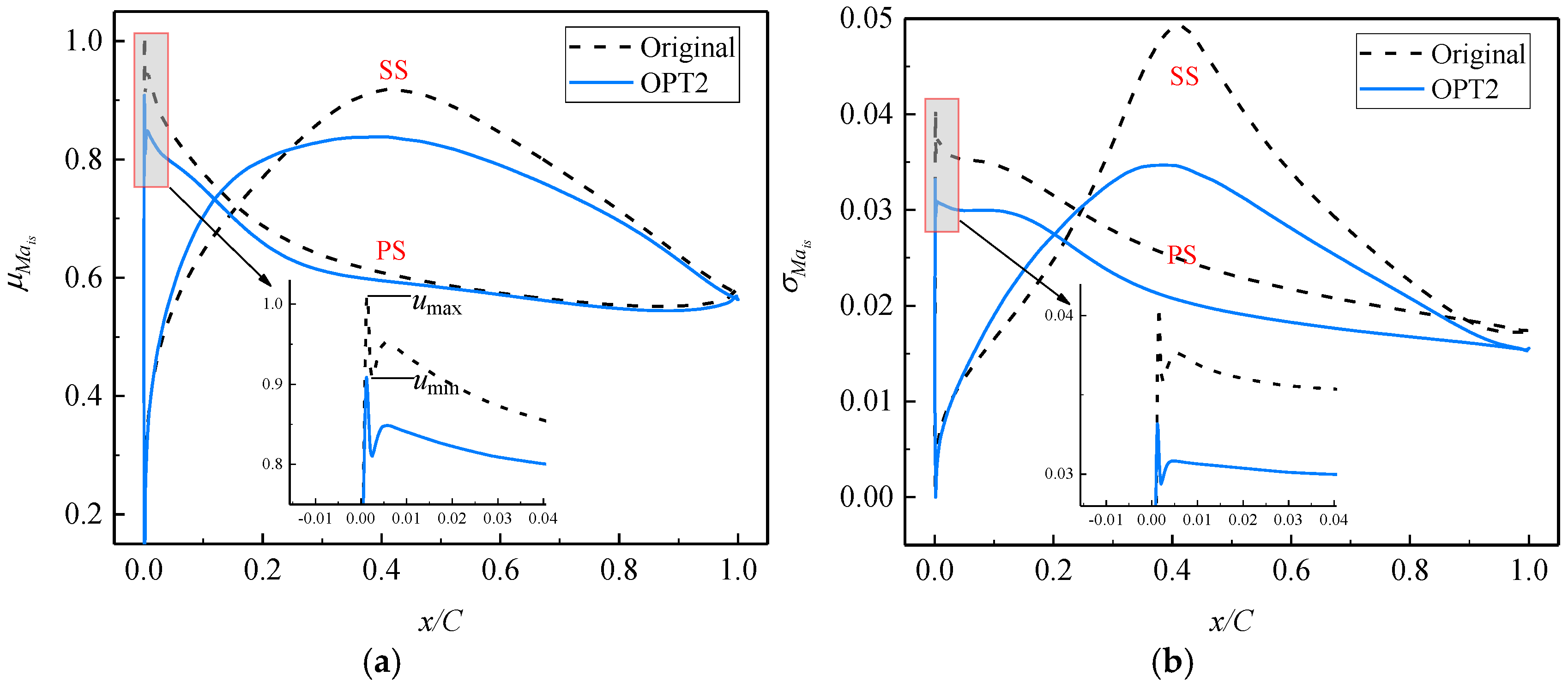
Figure 25 illustrates the distribution of
and
on the blade surface.
Figure 25a reveals significant alterations in the average flow near the velocity spike on the pressure side (PS) after robustness optimizations. The spike diffusion factor
Dspike provides a quantification of the spike strength [
49]:
where
umax and
umin are the velocities at the peak and subsequent trough on the spike, as in
Figure 25a. When
Dspike ≥ 0.10, the leading edge separation bubble occurs. A larger
Dspike corresponds to a more pronounced leading edge separation. The mean
Dspike on the PS of the original is approximately 0.1064, while that of OPT2 is around 0.1082. Hence, for OPT2, the average size of the leading edge separation bubble on the PS is expected to increase.
The results from
Figure 25a also indicate that after aerodynamic robustness optimizations, the average aerodynamic load on the suction side (SS) and PS notably decreases. This suggests that compared to the original, the boundary layer thickness on the SS and PS decreases.
Figure 26 compares the
distribution inside the blade passage between the original and OPT2. While OPT2 exacerbates separation flow at the leading edge of PS, its improvement in the boundary layer flow on the SS and PS is more pronounced. Therefore, OPT2 reduces the average global aerodynamic losses relative to the original and enhances the average diffusion capability in the airflow.
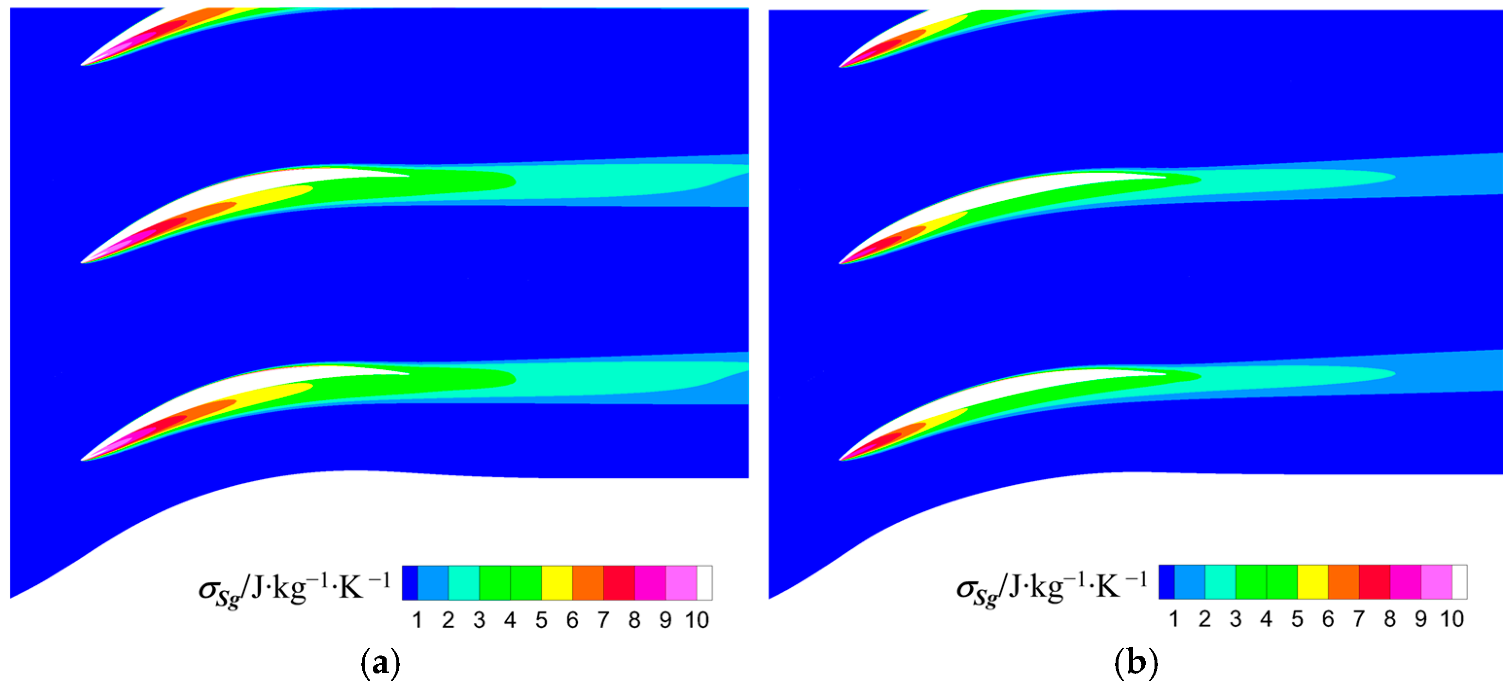
The
distribution on the blade surface shown in
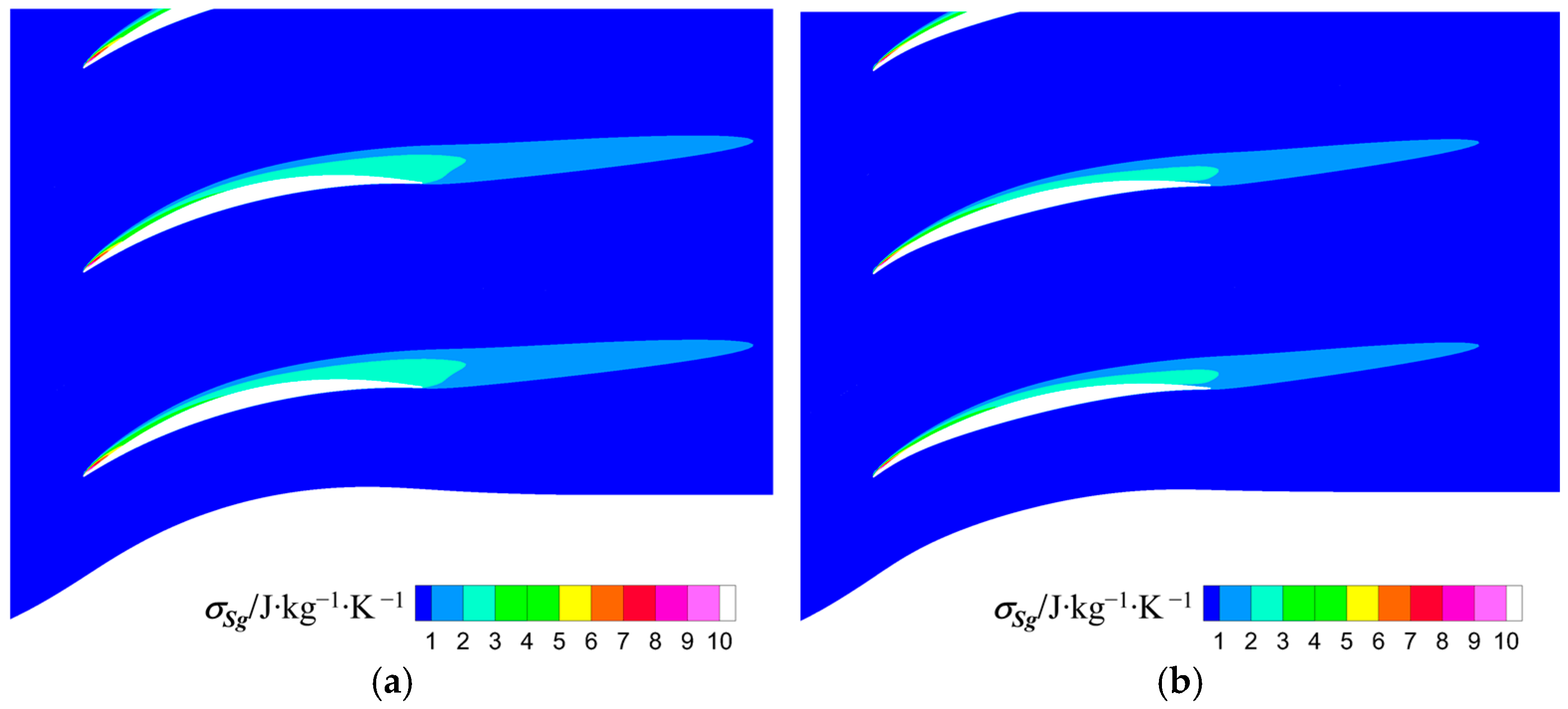
Figure 25b indicates that after robustness optimizations, the fluctuation amplitude of the velocity spikes at the leading edge of PS, as well as the aerodynamic load fluctuations on the SS and PS decreases. Consequently, for OPT2, the fluctuations in the leading edge separation and boundary layer losses decreases, leading to a reduction in the fluctuations of the global aerodynamic losses, as illustrated by the distribution of the standard deviation of entropy generation (
), shown in
Figure 27.
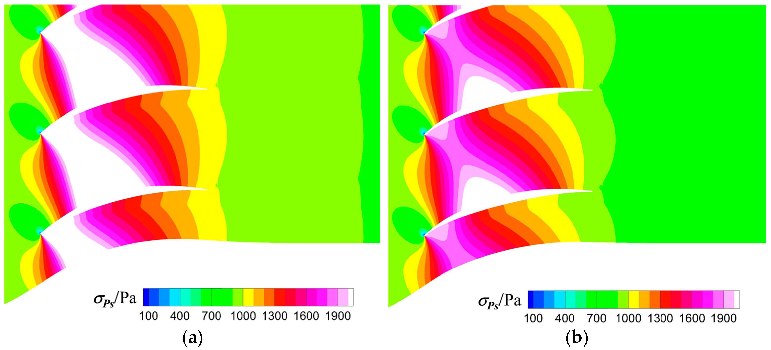
Figure 28 contrasts the standard deviations of static pressure,
σPs, inside the passage between the original and OPT2. Combining
Figure 28 with
Figure 25b, it can be inferred that due to the reduced fluctuation amplitude of the velocity spike at the leading edge of PS, and the significant reduction in aerodynamic load fluctuations on the SS, the fluctuations in the loading of the leading edge and SS decrease. As a consequence, for OPT2, the random disturbances of the diffusion capability are reduced.
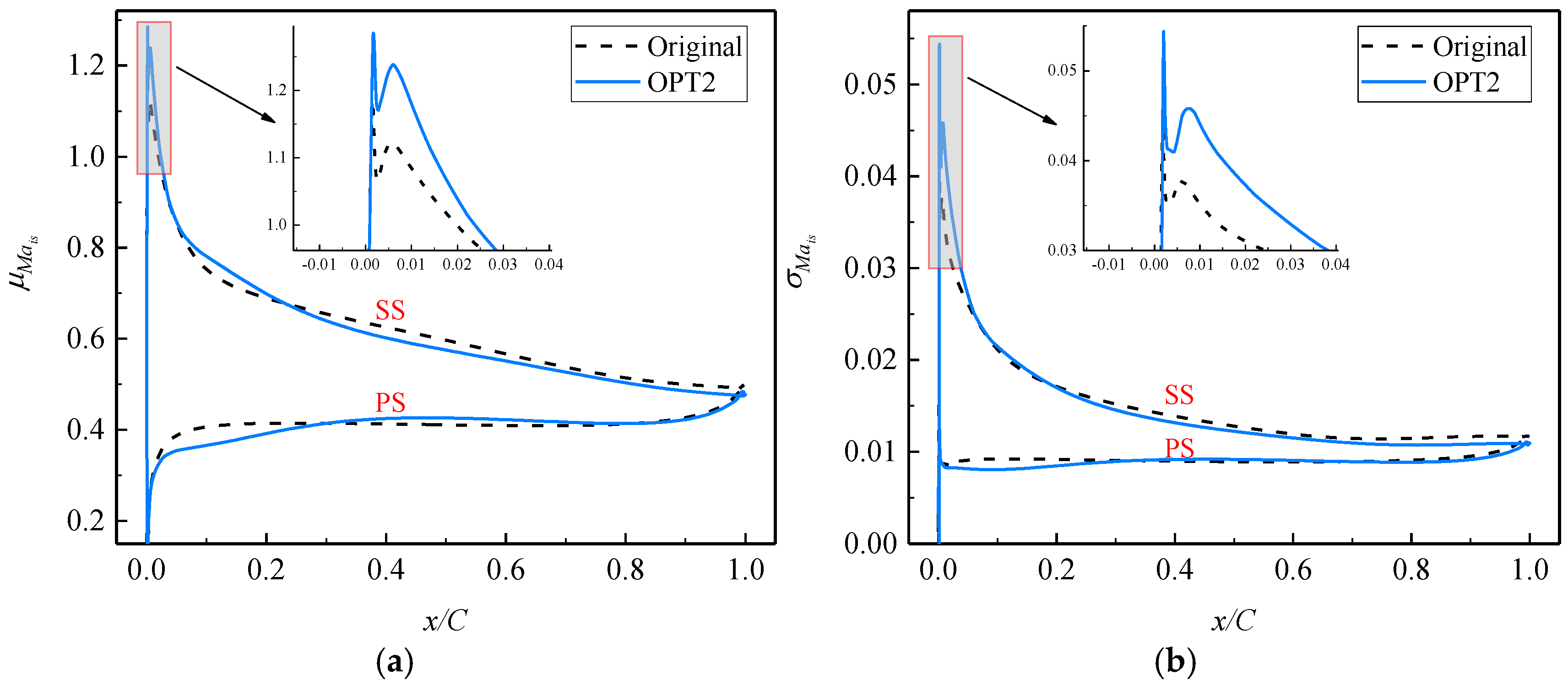
Then, the mechanism of improving aerodynamic robustness at
α = 9° was analyzed.
Figure 28 shows the distribution of
and
on the blade surface. In
Figure 29a, it is evident that following robustness optimizations, there is a substantial improvement in the average flow near the velocity spike on the SS. Through the calculation outlined in Equation (20), the mean
Dspike on the SS for the original is approximately 0.1020, whereas for OPT2, it is around 0.1001. As a result, OPT will decrease the average size of the leading edge separation bubble on the SS, compared to the original.
Research findings from references [
2,
44] suggest that the size of the leading edge separation bubble will impact the development of the downstream boundary layer.
Figure 30 provides the
distribution and average streamlines inside the passages for the original and OPT2. For OPT2, due to the reduction in the leading edge separation bubble on the SS, the thickness of the downstream boundary layer decreases, and the separation scale near the trailing edge of SS diminishes. Consequently, OPT2 lowers the average level of global aerodynamic losses and enhances its average ability to diffuse airflow.
Figure 29b shows that, although the fluctuation amplitude of the velocity spike at the leading edge of SS is increased for OPT2, the fluctuation amplitude of flows on the SS after the 20% chord decreases.
Figure 31 compares the distribution of
between the original and OPT2. For OPT2, the reduction in fluctuations caused by the boundary layer thickness over the SS leads to a decrease in the fluctuations of global aerodynamic losses. Hence, the reduction in fluctuations of the global losses for OPT2 is primarily due to the suppression of uncertainties in the flow on the SS after the 20% chord.
Figure 32 compares the distribution of
σPs inside the passage between the original and OPT2. Combining this with the analysis of
Figure 29b, it can be deduced that due to the increased aerodynamic load fluctuations at the leading edge of SS, the load variation on the front part of OPT2 is more pronounced, leading to an increase in random disturbances in the airflow diffusion process. Nonetheless, analysis from
Figure 21b indicates that the probability of the optimized blade’s
Cp being higher than that of the original is over 60%. Therefore, it can still be argued that OPT2 enhances the robustness of the blade’s diffusion capability at
α = 9°.


