Abstract
Elastic rings are extensively utilized in aero-engine rotor systems owing to their compact size and ease of assembly, where they play a critical role in vibration suppression during engine operation. The dynamic behavior of elastic rings is governed by their structural parameters, with stiffness being a pivotal factor influencing the rotor system’s performance. This study employs finite element methods to investigate the effects of elastic ring structural parameters, particularly the geometric features of bosses and internal/external assembly clearances, on stiffness nonlinearity, with a focus on its mechanisms and contributing factors. The results reveal that stiffness nonlinearity emerges when the whirling radius exceeds a critical threshold. Specifically, increasing the boss width, reducing the boss height, or augmenting the number of bosses all attenuate stiffness nonlinearity under identical whirling radii. Furthermore, external clearances exhibit a stronger capability to suppress stiffness nonlinearity compared to internal clearances. Engineering insights suggest that maintaining a small clearance fit during assembly effectively mitigates stiffness nonlinearity, thereby enhancing the rotor’s dynamic performance. This study elucidates the stiffness nonlinearity behavior of elastic rings in practical applications and provides actionable guidance for their design and operational optimization in rotor systems.
1. Introduction
Elastic support systems are core components of aero-engines [1,2]. Elastic rings, owing to their compact size and ease of assembly, have been widely adopted in aero-engine rotor support systems as a novel vibration reduction structure [3]. To ensure stable operation of aero-engines, the stiffness of elastic rings can be adjusted to regulate the critical speed of rotors [4,5]. Current research on elastic ring supports primarily focuses on the influence of parameter selection on support stiffness and dynamic characteristics.
As a critical elastic support, extensive studies have been conducted on the optimal selection of elastic ring properties and geometric parameters. A. Bormann and R. Gasch [6] proposed a methodology for optimizing material and geometric parameters of elastic rings by incorporating nonlinear static behavior and contact effects, experimentally demonstrating that even low system damping can reduce rotor vibration amplitudes and maintain stability. Diligenskiy D.S. et al. [7] established finite element and simplified models under varying parameters, revealing the significant impact of tolerance fits on elastic ring performance. Zhong Luo et al. [3] focused on the study of both three-dimensional and two-dimensional models of the elastic ring. They analyzed the stress distribution and the finite element models of the elastic ring for both approaches, comparing the advantages and disadvantages of each model. Additionally, the researchers conducted experiments to reveal the stiffness nonlinearity of the elastic ring and determined its critical load. They concluded that for calculating stiffness characteristics, the 2D model should be used, while the 3D model is more suitable for obtaining accurate stress distribution. Zhipeng Liu et al. [8] proposed a method for predicting the nonlinear contact behavior of elastic rings through numerical calculations and experimental analysis. This method incorporates a contact algorithm to prevent penetration and can effectively predict the deformation patterns, contact angles, stresses, and stiffness of elastic rings, thereby facilitating the optimal selection of geometric parameters and materials for elastic rings. This study enhances the theoretical foundation of contact elasticity in elastic rings and expands the engineering perspective for designing elastic rings in various contact scenarios.
Fundamental studies on elastic rings have also been explored. Hu Ding et al. [9] derived free vibration equations for rotating elastic rings, modeled nonlinear vibrations using Hamiltonian principles, and validated results via finite element analysis (FEA) and experiments. Ahmed M. Paridie et al. [10] studied the influence of the geometric shape of the elastic ring on its stiffness and damping coefficient. They developed a theoretical model, which was validated through finite element analysis, and used neural network training to predict the corresponding dynamic parameters. The predicted results showed good agreement with the experimental data. Chunguang Liu et al. [11] studied instability in rotating elastic rings, identifying unstable excitation frequency–stiffness fluctuation combinations through multiscale analysis and validating them via numerical integration and Floquet theory. G. L. Forbes et al. [12] analyzed modal shapes of elastic rings under moving loads, revealing differences between quasi-static modes under stationary loads and dynamic modes under moving loads. Stelian Alaci et al. [13] derived the stress state equation for the outer boundary of an eccentric elastic ring under symmetric loading from a concentrated force. They studied six loading conditions for two different geometric shapes of the ring and validated all the analyses through experiments, identifying the stress concentration effect at the inner hole.
As elastic rings effectively mitigate rotor vibrations, studies on rotor systems incorporating elastic rings have been conducted. H.M. Navazi et al. [14] investigated the vibrations and stability of unbalanced rotors with nonlinear supports, demonstrating the reliability of numerical methods for stiffness modeling. Zharilkassin Iskakov et al. [15] investigated the impact of stiffness nonlinearity and damping nonlinearity in the transitional state on the rotor frequency characteristics. They proposed a method for identifying the nonlinear stiffness of bearing materials, linear damping, and nonlinear cubic damping coefficients, which was validated through numerical methods. Zhou Jilai et al. [16] established a 5-DOF rotor model with elastic ring supports, comprehensively considering the strong coupling effects between the elastic supports and bearings. Through finite element methods and experimental results, they investigated the effects of different fits and dynamic stiffness on the critical speed of the rotor system. The study revealed that elastic supports can reduce the frequency components of the vibration response and make the vibration modes of the rotor system resemble rigid body modes, thereby reducing the system’s maximum vibration displacement. Kai Sun et al. [17] proposed and validated a variable stiffness model for the elastic ring. By coupling the rotor’s dynamic equations with the deformation of the combined support, they developed a variable stiffness model for a rotor supported by an elastic ring. Through the analysis of the rotor system’s dynamic characteristics, they investigated the effect of the elastic ring’s variable stiffness on the system’s critical speed. The results were validated through a combined experimental setup, revealing that the variable stiffness of the elastic ring has no impact on the critical speed of the rotating system with a lower imbalance mass. However, the clearance of the elastic ring can reduce the rotor’s critical speed.
Additionally, elastic rings are also integral to the elastic ring squeeze film damper (ERSFD). The elastic ring deforms under compression, which allows for further adjustment of the oil film thickness based on the external load, providing better support and vibration damping for the rotor system. The design of the elastic ring within the damper helps to reduce the highly nonlinear oil film pressure behavior, compared to traditional squeeze film dampers, making it widely applicable in engineering. Currently, most research focuses on the influence of the parameters of the elastic ring-type squeeze film damper on its dynamic characteristics. Wei Zhang et al. [18] studied the deformation characteristics of the elastic ring under oil film compression in an elastic ring squeeze film damper (ERSFD) using the finite element method. They analyzed the complexity of the deformation process and revealed that the application of the elastic ring can effectively mitigate the nonlinear behavior in bearing capacity, oil film stiffness, and damping characteristics. This finding helps in understanding the advantages of ERSFDs in addressing the common nonlinear issues encountered in traditional squeeze film dampers. Zhenlin Wang et al. [19] investigated the contact behavior between the elastic ring and the journal using a simplified Greenwood–Williamson model. They discovered high-order frequency components in the oil film pressure spectrum that are related to the number of bosses, providing significant guidance for material selection in ERSFDs to reduce unnecessary vibrations in rotor systems. Weitao Chen et al. [20] proposed a semi-analytical method based on the generalized Reynolds equation to calculate the deformation of the elastic ring in ERSFDs and combined it with the dynamic model of gear transmissions. Their study highlighted the significant advantages of ERSFDs in improving system stability and vibration attenuation, as well as advancing the study of dynamic characteristics when combined with gear systems. Yongxiang Xu et al. [21] explored the effects of orifice size and distribution on the damping characteristics of ERSFDs using finite element analysis. They proposed an optimized configuration for adjusting the damping coefficient through orifice design and discovered that the oil film force varies with the orifice location. The oil film force reaches its minimum value when the orifice radius is adjusted to maximize damping. Their study revealed that the optimal circumferential position of the orifices should be at half the oil film’s length, while the optimal axial position is determined by the distance between the orifices and the pressure level around them. These studies underscore the importance of addressing nonlinear deformation, contact behavior, and orifice design in ERSFD development. Future research could focus on integrating multi-disciplinary approaches, such as advanced fluid–structure interaction simulations and experimental validation, to further refine ERSFD designs for high-dynamic-load and complex operational conditions. Additional studies [22,23,24,25,26] explored ERSFD performance under varied operating conditions. However, existing research predominantly focuses on oil-lubricated ERSFDs, with limited attention paid to dry elastic rings as standalone supports, necessitating further investigation into stiffness nonlinearity without oil films.
In existing aero-engine rotor systems, the primary supports employed are oil-lubricated elastic rings or squirrel cages, both of which effectively provide vibration attenuation. The current literature focuses on the influence of elastic ring structural parameter variations on the dynamic characteristics of ERSFDs and the selection of parameters of ERSFDs. Even in studies directly focusing on elastic rings, researchers typically concentrate on how structural parameters and materials affect stress distribution, deformation, and stiffness.
However, an elastic ring without oil lubrication was adopted in the rotor support system, which was employed in a specific model of aero-engine of our institute. As a critical component of the rotor system’s support structure, elastic ring parameters significantly affect rotor critical speeds [27,28]. In current research and engineering practices, elastic rings are mainly designed with oil-lubricated configurations. However, studies on non-oil-lubricated or minimally fuel-lubricated elastic rings remain scarce, and such rotor support systems are rarely implemented in practical engineering applications. In tests of this engine, the elastic ring design stiffness of the rotor system’s Support 1 was 2 × 10⁷ N/m. Samcef V17 was used to analyze the rotor system, and the first two critical speeds were found to be 8097 r/min and 24,020 r/min, respectively. However, experimental observations revealed unexpected critical speed shifts toward higher values, suggesting potential correlations with support stiffness variations [29,30]. This phenomenon underscores the necessity to investigate stiffness nonlinearity behaviors in non-oil-lubricated elastic rings.
To elucidate the nonlinear stiffness characteristics of elastic rings and the influence of structural parameters, this study analyzes stiffness and maximum stress calculation methods for ring segment models. A finite element model is developed to investigate the effect of rotor whirl radius on stiffness, validated against experimental data. This study aims to explore how the geometric features of the elastic ring bosses (including boss height, boss width, and the number of bosses) and assembly clearances affect the nonlinear variation in elastic ring stiffness. By examining the impacts of various parameters on the phenomenon of stiffness nonlinearity, our objective is to optimize these parameters to mitigate the nonlinear increase in stiffness, thereby enhancing rotor system stability and supporting the reliable operation of aero-engines.
The remainder of this paper is organized as follows. Section 2 presents the theoretical model for the stiffness calculation of the elastic ring. Section 3 details the establishment and validation of the finite element model. Section 4 analyzes the effects of structural parameters on stiffness nonlinearity. Finally, Section 5 summarizes the key conclusions for this paper.
2. Theoretical Model of Elastic Ring Calculation
The structure of the elastic ring studied in this paper is illustrated in Figure 1. The ring features uniformly distributed bosses on both its inner and outer sides. The inner side interfaces with the bearing outer ring, while the outer side interfaces with the casing. Given that the thickness of the elastic ring is significantly smaller than its radius, each segment of the ring can be analyzed independently by simplifying it as a fixed-end straight beam [31].
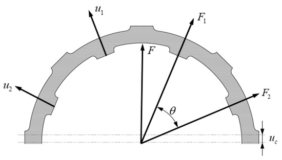
Figure 1.
Structure of elastic ring.
In the simplified segment model, the compliance δ0 of a fixed-end beam with a uniform cross-section is given by the following:
where L is the length of each segment, E is the elastic modulus, and I is the moment of inertia of the cross-section.
For the simplified model, the moment of inertia I can be calculated as follows:
where b is the width of the elastic ring, and h is its thickness.
By analyzing each segment similarly, the displacement ui of each segment under a central displacement uc and applied load Fi can be expressed as follows:
where θn = 2π and n is the number of bosses on the elastic ring.
The load Fi acting on each segment can be further derived as follows:
Considering the symmetry of the elastic ring, the total load F acting on the ring can be calculated as follows:
Finally, the stiffness K of the elastic ring is obtained as follows:
If the load F is applied directly to the central cross-section of a segment, the maximum stress occurs at the ends of the segment. The force acting on the segment F0 can be expressed as follows:
Given the thickness h, width b, and length l of the segment, the maximum stress σ at the ends of the segment can be calculated as follows:
The theoretical calculation formulas can only provide an approximate estimation of the order of magnitude of the elastic ring’s radial stiffness, offering some guidance in the design process but failing to precisely determine its exact stiffness value.
The geometric parameters of the elastic ring are shown in Figure 2. In practical engineering applications, approximate analytical formulas are commonly used during the design phase to improve the accuracy of stiffness predictions [32].
where m is the number of bosses; E is the elastic modulus; s is the thickness of the elastic ring; Δ is the boss height; L is the axial length of the elastic ring; b1 is the boss width; d is the chamfer diameter at the boss root; D1 is the inner diameter of the elastic ring and D2 is the outer diameter of the elastic ring. A is a process parameter and can be calculated using the following equation:
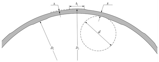
Figure 2.
Geometric parameters of elastic ring.
However, these formulas are limited to estimating radial stiffness and cannot accurately capture the stress distribution or strength characteristics of the elastic ring. Therefore, after the preliminary design stage, finite element methods [33,34] should be employed to analyze the stiffness, stress distribution, and other mechanical properties of the elastic ring. This approach ensures a more accurate assessment of its dynamic characteristics, thereby contributing to the stable operation of the rotor system.
3. Establishment and Validation of Finite Element Model
3.1. Finite Element Model of Elastic Ring
A finite element model was developed in Ansys 2020 based on the elastic ring of a certain type of aero-engine. The meshed model is illustrated in Figure 3. The geometric parameters of the elastic ring are listed in Table 1, with the material specified as 9Cr18Mo. Axial displacement constraints were applied to the elastic ring, while all degrees of freedom of the bearing housing outer ring were fully constrained.
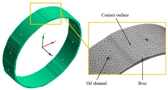
Figure 3.
Finite element model of elastic ring.

Table 1.
Geometric parameters of elastic ring.
As shown in Figure 4, the rotor typically operates in a steady-state synchronous whirl at a given eccentricity. The coordinate origin O is defined as the bearing center. While the rotor spins about its own axis, its geometric center C deviates from the bearing center O by distance e. The rotor’s geometric center C orbits around the bearing center O along a circular path with a radius. This distance e is referred to as the whirl radius of the rotor.
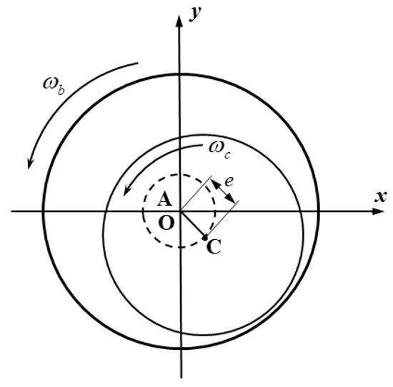
Figure 4.
Structure and coordinates of rotor system.
To simplify the model, our finite element analysis assumes that the rotor center follows a circular trajectory rather than an elliptical one. Additionally, although the contact conditions of the elastic ring vary with the radial angle in practice, the model assumes that the stiffness of the elastic ring is constant across all circumferential directions. Furthermore, when analyzing the parameters of boss height, boss width, and the number of bosses, we conducted the analysis assuming no assembly clearance to avoid the influence of varying inner and outer clearances on the ring’s stiffness. It should be noted that in actual applications, clearances between the elastic ring and the inner or outer rings inevitably exist.
To enhance computational accuracy and efficiency, the finite element model of the elastic ring was discretized using structured hexahedral elements with a minimum element size of 0.2 mm. In regions with complex geometrical features, such as around the bosses and oil channels, local mesh refinement was applied to ensure accurate capture of stress gradients and contact behavior. For the contact interfaces between the bosses and the shaft journal, as well as the bearing outer ring, three-dimensional surface contact elements CONTA174 (contact surface) and TARGE170 (target surface) were employed to simulate frictional contact behavior, with a friction coefficient set to 0.2. The contact algorithm used the augmented Lagrangian method, and the contact stiffness coefficient was set to 0.1.
To ensure grid independence, a systematic mesh convergence study was performed by progressively refining the global element size from 0.5 mm down to 0.1 mm. The results showed that when the element size is below 0.2 mm, variations in both the maximum stress and computed stiffness of the elastic ring are less than 5%, confirming that a mesh size of 0.2 mm satisfies the convergence criteria.
Figure 5 shows the theoretical and calculated stiffness values of the elastic ring used in a specific engine. The red curve represents the theoretical stiffness, while the black curve corresponds to the finite element simulation results. The design stiffness is 2 × 10⁷ N/m. Based on the model, the linear stiffness is 2.18 × 10⁷ N/m when the whirl radii are less than 0.19 mm. Beyond this threshold, the stiffness exhibits a nonlinear increase, leading to changes in the rotor’s critical speed, consistent with engineering observations described in Section 1. The whirl radius at which the stiffness begins to exhibit nonlinear behavior is defined as the transition point. Beyond this point, the stiffness increases with increasing whirl radius.
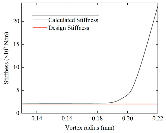
Figure 5.
Relationship between elastic ring stiffness and whirl radius.
The calculated stiffness of the elastic ring deviates from the design stiffness by 9%, which is within the allowable error range. If a fitting calculation is performed using Equation (9), the resulting value is typically higher than the actual stiffness of the elastic ring. Moreover, because the fitting formula does not fully account for all geometric features of the elastic ring, the stiffness computed by this equation does not exhibit any nonlinear characteristics.
In general, engineering design is based on an elastic design approach, assuming that material deformation is recoverable. However, when the whirl radius is relatively large, the contact of the elastic ring’s bosses has entered the plastic deformation stage. Figure 6 presents the stress–strain curves of the material 9Cr18Mo used in the elastic ring at different strain rates [35].
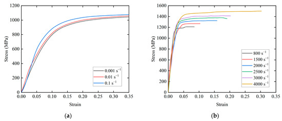
Figure 6.
Stress–strain curves of 9Cr18Mo (T = 298.15 K). (a) In quasi-static state (strain rate = 0.001 s−1, 0.01 s−1, and 0.1 s−1); (b) at different strain rates (strain rate = 800 s−1, 1500 s−1, 2000 s−1, 2000 s−1, 2500 s−1, 3000 s−1, and 4000 s−1).
Figure 7 shows the Von Mises stress at the bosses at different stages. At smaller whirl radii, the deformation at the bosses is minimal, and the stress value is below the yield strength, indicating that the material is in the elastic stage at smaller whirl radii, and thus the stiffness remains constant. As shown in Figure 6, when the whirl radius is large, the deformation at the bosses is significant, and the stress value exceeds the yield strength. This indicates that, at larger whirl radii, the material enters the plastic deformation stage, and part of the height of the bosses has been flattened, resulting in a nonlinear increase in stiffness.
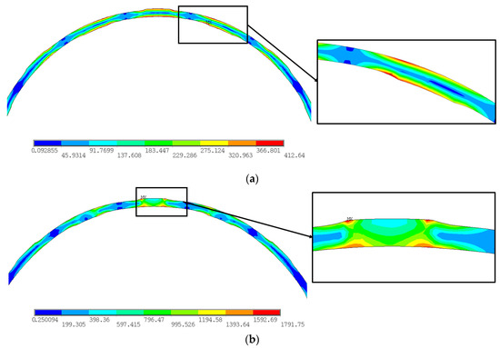
Figure 7.
Von Mises stress distribution on elastic ring bosses. (a) Vortex radius = 0.08 mm and stress maximum = 412.64 MPa; (b) vortex radius = 0.23 mm and stress maximum = 1791.75 MPa.
When the bosses of the elastic ring enter the plastic state, the theoretical calculation formula described in Section 2 is no longer applicable for the stiffness of the plastic contact area. A nonlinear material constitutive model should be introduced for analysis [36].
In the strain space, based on the stress–strain relationship in the elastic stage, the total strain increment dε consists of the plastic strain increment dεp and the elastic strain dεe increment. The plastic strain accounts for the loading history. To determine the stress, it is necessary to obtain the plastic strain increment dεp within the total strain increment.
Considering the known relationships among the strain increments,
Given the elastic modulus E, the stress increment dσ can be calculated from the elastic strain increment:
And the plastic modulus H can be expressed as follows:
Given the tangent modulus Et and considering the interrelationship between the elastic modulus E, plastic modulus H, and tangent modulus Et, the stress increment dσ in the plastic stage can be expressed as follows:
Substituting Equation (14) into Equation (11) yields the plastic modulus; the plastic modulus H can be obtained:
Furthermore, the plastic component of the total strain increment dεp can be determined from Equation (11):
And it can also be expressed as follows:
For the elastic ring structure, we use a similar method as before for beam element analysis, as shown in Figure 8.
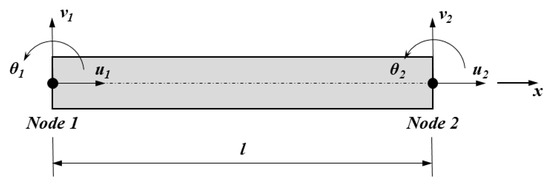
Figure 8.
The beam model in FEA.
Given the displacement arrays u of the beam element:
where u1, v1, u2, and v2 represent the deflections at nodes 1 and 2, respectively, and θ1 and θ2 represent the shapes at nodes 1 and 2.
For the elastoplastic finite element solution, we employ the Newton–Raphson method [37]. Assuming that the load is independent of the deformation, the basic equation for the nonlinear problem at time t + Δt is as follows:
where R and Q represent the externally applied nodal force and the equivalent nodal force corresponding to the distributed load, respectively.
In this finite element problem, an incremental load is applied. If the load increment at time t is denoted as n, then the load increment at time t + Δt is n + 1. This small load increment produces a corresponding small displacement increment. Focusing on the load increment at n + 1, the finite element equilibrium requirement can be reduced to solving the following equation:
where u* is the complete array of the solution.
In the m-th iteration (m = 1, 2, 3, …), a Taylor series expansion is applied to Equation (20), neglecting higher-order terms so that the displacement increment dum can be calculated as follows:
where is the current tangent stiffness matrix, which can be obtained by the following:
Subsequently, the displacement increment is given by the following:
Given the shape function matrices [Nu] and [Nv], the displacement increment functions dv1 and dv2 can be expressed as follows:
Further, the strain increment dε can be derived as follows:
Given the geometric function matrix [B], the strain increment dε in Equation (25) can be expressed as follows:
where [B] can be obtained by the following:
Based on the virtual displacement principle, the weak form of the element equilibrium equation is as follows:
where ūT is the virtual displacement array at the nodes, and R and Q are the equivalent nodal forces for the element and the distributed loads, respectively.
Considering the nonlinear relationship between material stress and strain in the plastic stage, the linearized equilibrium equation after the equilibrium equation is simplified becomes as follows:
By solving Equation (29), the tangent stiffness matrix kt can be obtained:
The residual e during the iteration process is defined as follows:
It is essential to ensure that the residual after each iteration is 0 to satisfy the element equilibrium Equation (29). The node stress σ in the plastic state is given by the following:
where σn is the stress from the previous state, εp,n is the accumulated plastic strain after the n-th iteration, and dεm is the strain increment.
Considering the material properties and model content, we employed the Johnson–Cook model in Ansys to establish the finite element analysis [35], and its expression for true stress is as follows:
where a is the yield stress, b is the hardening modulus, εp is the equivalent plastic strain, n is the material hardening exponent, c is the strain rate hardening parameter, ε0 is the reference strain, Tk is the temperature-dependent term, Tm is the melting temperature, and Tr is reference temperature.
3.2. Validation of the Finite Element Model
To validate the model, the stiffness nonlinearity induced by contact behavior, as studied by Zhifei Han et al. [38], was replicated. An elastic ring model with eight bosses was constructed, and stiffness values were calculated for three thicknesses: 0.5 mm, 0.7 mm, and 0.95 mm. Table 2 compares the results with theoretical and reference data. The fitting stiffness was derived from the analytical stiffness Formula (9), Han’s stiffness was obtained from the reference [38], and the proposed finite element method (FEM) stiffness was derived from the finite element analysis of the model.
Table 2.
Comparison of elastic ring stiffness calculations.
By constructing the elastic ring model described in the literature and comparing the finite element analysis results, we found that the stiffness error of the elastic ring model is within 10%. Compared with the stiffness values obtained from the fitting formula, our finite element calculations demonstrate greater reliability and accuracy. Furthermore, as shown in Figure 7, the maximum displacement of the elastic ring at a larger whirling radius is 0.252 mm. Considering the mean diameter of the elastic ring (56.5 mm) as the reference dimension, the displacement-to-dimension ratio is approximately 0.0045, indicating that the deformation of the elastic ring is much smaller than its characteristic dimension and that the model satisfies the small deformation assumption. Based on these analyses and results, the fitting formula is only reasonably reliable when the elastic ring thickness is relatively large, and it does not capture the complete stiffness characteristics of the elastic ring [39].
4. Results and Analysis
4.1. Whirl Radius
As discussed in Section 3.1, the existing theoretical calculation models and fitting stiffness formulas for the elastic ring cannot fully account for changes in the structure of the elastic ring, and they fail to accurately represent complex stress distributions. Therefore, finite element simulation and experiments provide a more accurate representation of the actual stress distribution of the elastic ring.
At larger whirl radii, the bosses of the elastic ring experience significant compression, leading to plastic deformation and nonlinear changes in stiffness. Figure 9 shows the Von Mises stress distribution of the elastic ring during the plastic deformation stage, at which point the elastic ring no longer meets the original design requirements and fails. At larger whirl radii, there are six locations on the elastic ring with relatively high equivalent stress, and these points labeled with capital letters can be used as strength assessment points. The stiffness of the elastic ring is directly related to the dynamic characteristics of the rotor system it supports. Therefore, in finite element simulations, special attention is given to the six assessment points shown in the figure.
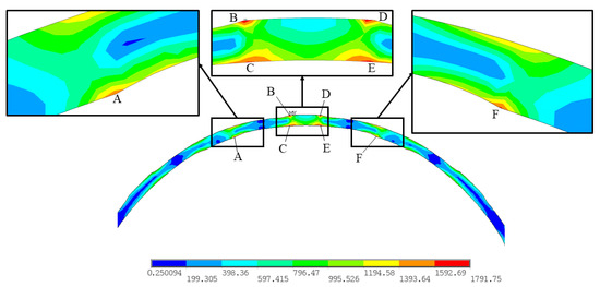
Figure 9.
Von Mises stress distribution of elastic ring with whirl radius of 0.23 mm. The locations labeled with capital letters are strength assessment points.
Figure 10 illustrates the relationship between the maximum stress on the bosses and the whirl radius. In the elastic region, the stress increases linearly with the whirl radius. In the plastic region, the stress increases more rapidly due to plastic deformation, causing the elastic ring to deviate from its design requirements.
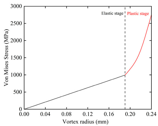
Figure 10.
Relationship between maximum stress on bosses and whirl radius.
4.2. Boss Width
To study the influence of boss width on stiffness nonlinearity, the geometric parameters from Table 1 (Section 3.1) were modified by varying the boss width. The whirl radius at which stiffness nonlinearity occurs was observed for different boss widths. Figure 11 shows the relationship between the whirl radius at the stiffness nonlinearity transition point and the boss width.
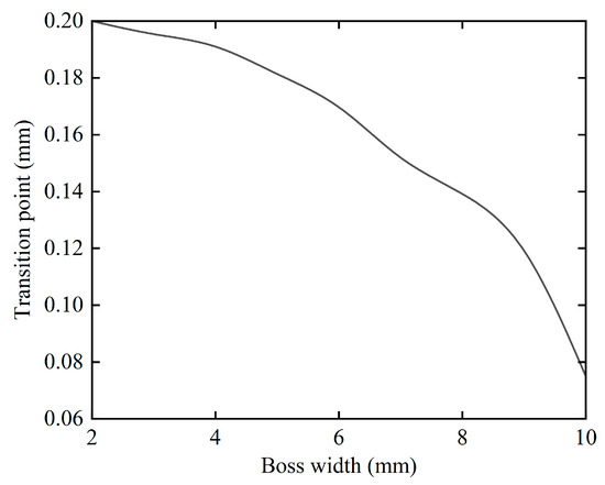
Figure 11.
Relationship between whirl radius at stiffness nonlinearity transition point and boss width.
As the boss width increases, the whirl radius corresponding to the stiffness nonlinearity transition point decreases. For example, at a boss width of 6 mm, the transition occurs at a whirl radius of approximately 0.172 mm, while at 10 mm, it occurs at 0.07 mm.
For practical engineering applications, the boss width of the elastic ring typically ranges between 2 mm and 8 mm. Our study indicates that when the boss width exceeds 6 mm, the whirl radius at which stiffness nonlinearity occurs decreases more rapidly. Specifically, as the boss width increases from 2 mm to 6 mm, the whirl radius for the onset of stiffness nonlinearity decreases from 0.2 mm to 0.172 mm. However, further increases in boss width result in a significant reduction in this critical whirl radius. Therefore, in the design of elastic rings, it is advisable to maintain the boss width between 2 mm and 6 mm. When designing rotor systems, adjusting the boss width of the elastic ring can be an effective means to change its stiffness, thereby influencing the critical speed and vibration modes of the rotor system.
4.3. Boss Height
To investigate the effect of boss height on the nonlinearity of elastic ring stiffness, the geometric parameters of the elastic ring in Table 1 of Section 3.1 were used as the prototype. The variation in boss height leads to a change in the width of the elastic ring, thereby altering the ratio of boss height to elastic ring width δ. The ratios considered were 7.69%, 12.5%, 18.18%, 25%, 33.33%, and 43.75%. As δ increases, the boss height relative to the elastic ring width becomes larger, indicating a stronger load-bearing capacity of the boss. Elastic ring stiffness was calculated at different whirl radii to observe the emergence of stiffness nonlinearity. Figure 12 shows the relationship between the whirl radius at the stiffness nonlinearity transition point and the δ ratio.
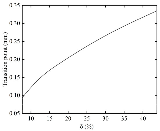
Figure 12.
Relationship between whirl radius at stiffness nonlinearity transition point and ratio δ.
As δ increases, the whirl radius at which stiffness nonlinearity occurs also increases. This means a smaller whirl radius is more likely to induce stiffness nonlinearity at smaller values of δ. However, as δ increases, nonlinearity in stiffness will only occur once the whirl radius exceeds a certain threshold, thereby affecting the rotor’s critical speed.
Based on the findings, during the elastic ring design phase, the ratio δ should not be set too low. Taking the elastic ring described in Section 3.1 as an example, the inner and outer diameters of the ring in the engine rotor system remain constant, establishing an inherent relationship between the ring thickness and boss height. For this elastic ring, the suitable design range for the boss height is between 0.1 mm and 0.35 mm. Considering that the rotor whirl radius should not be excessively high, we should ensure that the turning point for the onset of stiffness nonlinearity is located at a whirl radius of 0.18 mm or higher. This means the ratio δ should be kept above approximately 20%, meaning the boss height should be at least 0.2 mm.
Furthermore, practical engineering constraints dictate that elastic ring thickness cannot be less than 1 mm. As a result, the ratio δ should not exceed 30%, implying that the maximum boss height should be limited to 0.3 mm. Therefore, for the elastic ring in Section 3.1, a boss height in the range of 0.2 mm to 0.3 mm is considered more appropriate in order to optimize stiffness performance while satisfying the operational requirements of the rotor system.
4.4. Number of Bosses
The effect of the number of bosses on stiffness nonlinearity was studied by varying the number of bosses (even numbers between 6 and 16). Figure 13 shows the relationship between the whirl radius at the stiffness nonlinearity transition point and the number of bosses.
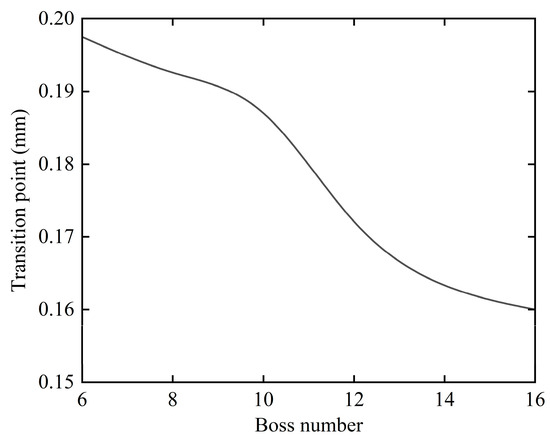
Figure 13.
Relationship between whirl radius at stiffness nonlinearity transition point and number of bosses.
As the number of bosses on the elastic ring increases, the whirl radius at which the elastic ring stiffness exhibits nonlinearity slightly decreases. However, the number of bosses has a minimal effect on the nonlinearity of the elastic ring stiffness. For example, the transition occurs at 0.197 mm with 6 bosses, while with 16 bosses, it occurs at 0.16 mm. This indicates that the number of bosses does not significantly affect the nonlinearity of elastic ring stiffness.
In the practical design of rotor–elastic support systems, designers need to adjust the rotor’s critical speed by modifying the stiffness of the elastic support. The number of bosses significantly affects the stiffness of the elastic ring, often leading to changes in magnitude. Such variations can cause substantial shifts in the rotor system’s critical speed and mode shapes. Therefore, it is not recommended to suppress the nonlinear stiffness behavior of the elastic ring by altering the number of bosses.
4.5. Clearance Fit
In practical engineering, the elastic ring cannot be assembled without any gap between the inner and outer components. Typically, there is a certain assembly clearance between the internal and external parts. In actual assembly, small clearance fits are commonly used, with the assembly gap usually not exceeding 0.02 mm. For the clearance between the outer ring of the elastic ring and its mating surface, commonly used small clearance values of 0.005 mm, 0.01 mm, 0.015 mm, and 0.02 mm are selected for investigation. Figure 14 shows the variation in the maximum equivalent stress of the elastic ring with whirl radius under these four clearance conditions. As the outer clearance increases, the whirl radius corresponding to the onset of plastic deformation in the elastic ring also increases.

Figure 14.
Relationship between maximum stress and whirl radius for different outer clearances.
Table 3 presents the corresponding whirl radii at the transition points of stiffness nonlinearity for these four outer clearance values. This indicates that larger outer fitting clearances are more effective in suppressing the nonlinear variation in the stiffness of the elastic ring.
Table 3.
Relationship between outer clearance and whirl radius at stiffness nonlinearity transition.
For the inner clearance of the elastic ring, small clearances commonly used in engineering—0.005 mm, 0.01 mm, 0.015 mm, and 0.02 mm—were selected for study, similar to the outer clearance. Figure 15 shows the variation in the maximum equivalent stress in the elastic ring with respect to the whirl radius under these four clearance conditions. As the inner clearance increases, the whirl radius corresponding to the onset of plastic deformation in the elastic ring also increases. Table 4 provides the whirl radius values at the stiffness nonlinearity transition point for these four inner clearance conditions. Similar to the outer clearance, this indicates that larger inner clearances are more effective in suppressing the nonlinear variation in the stiffness of the elastic ring.
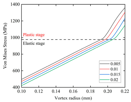
Figure 15.
Relationship between maximum stress and whirl radius for different inner clearances.
Table 4.
Relationship between inner clearance and whirl radius at stiffness nonlinearity transition.
Based on the analysis of Table 3 and Table 4, when stiffness nonlinearity occurs, the maximum equivalent stress of the elastic ring is approximately 970–980 MPa. At this point, the stress evaluation points on the elastic ring bosses (as shown in Figure 9) have entered the plastic deformation stage. Simulation results for both the inner and outer clearances show that the outer clearance has a stronger ability to suppress stiffness nonlinearity. Compared to the same inner clearance value, the outer clearance can be more effective in delaying the onset of stiffness nonlinearity behavior.
Figure 16a shows the Von Mises stress distribution of the elastic ring with an inner clearance of 0.05 mm and a whirl radius of 0.18 mm. The maximum equivalent stress at the stress evaluation points is 689.031 MPa. Figure 16b shows the stress distribution of the elastic ring with an outer clearance of 0.05 mm and a whirl radius of 0.18 mm, with the maximum equivalent stress at the stress evaluation points being 663.803 MPa.
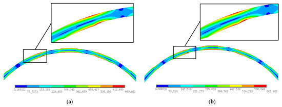
Figure 16.
Von Mises stress distribution on elastic ring bosses with a whirl radius of 0.18 mm. (a) Inner clearance = 0.05 mm, outer clearance = 0 mm, and stress maximum = 689.031 MPa; (b) inner clearance = 0 mm, outer clearance = 0.05 mm, and stress maximum = 663.803 MPa.
For the same assembly clearance value, it is evident that the outer clearance has great effects on lowering the stress level at the stress evaluation points on the bosses, reducing the plastic deformation occurring at the bosses, and thus delays the occurrence of nonlinearity. Variations in assembly clearances influence stiffness nonlinearity behavior through the combined effects of plastic deformation and contact nonlinearity, which means that delaying plastic deformation is not the only contributing factor. Under varying assembly clearance conditions, the contact states between the inner bosses and the journal, as well as between the outer bosses and the bearing outer ring, transition from full to partial contact. These transitions are generally attributed to elliptical deformation or insufficient interference, as detailed in a recent study [40].
Furthermore, even when assembly clearances are maintained, nonlinear stiffness may vary circumferentially. Variations in the number of boss contacts alter the load distribution, which in turn further influences the circumferential stiffness of the elastic ring. These observations highlight the importance of carefully optimizing both boss geometry and assembly clearance to enhance the performance and stability of rotor support systems.
Based on the simulation results and practical engineering considerations, assembly clearances of 0.02 mm for the outer boss clearance and 0.015 mm for the inner boss clearance were selected for comparison between the cases with and without clearance. Figure 17 shows the computational results of elastic ring stiffness as a function of whirl radius for both the cases with and without clearance. When there is no clearance between the elastic ring’s inner and outer bosses and the bearing outer ring and bearing housing, nonlinear stiffness occurs at a whirl radius greater than 0.195 mm. In contrast, when there is clearance between the elastic ring’s inner and outer bosses and the bearing outer ring and bearing housing, nonlinear stiffness occurs at a whirl radius greater than 0.209 mm.
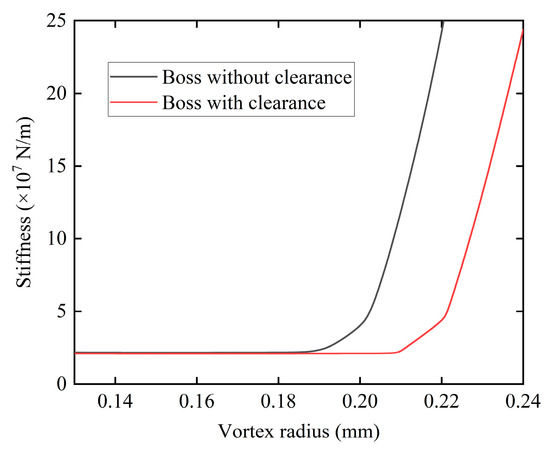
Figure 17.
Stiffness variation with whirl radius for different clearance conditions.
5. Conclusions
This study analyzed a theoretical model for calculating the stiffness of elastic rings, established a finite element model based on engineering practice, and investigated the influence of structural parameters on stiffness nonlinearity. The following conclusions are drawn:
- Finite element analysis of the elastic ring provides a more accurate representation of its stiffness characteristics. Fitting stiffness formulas, which consider only geometric parameters of the elastic ring, fail to capture nonlinear behavior. As the rotor whirl radius increases, the elastic ring exhibits nonlinear stiffness due to plastic deformation at the bosses, where partial flattening occurs. At larger whirl radii, regions with higher equivalent stress should be selected as critical points for fatigue life assessment.
- Geometric parameters of the elastic ring, such as boss width, the ratio of boss height to ring thickness, and the number of bosses, significantly influence the onset of stiffness nonlinearity. Reducing the boss width or increasing the ratio of boss height to ring thickness mitigates stiffness nonlinearity at the same whirl radius, preventing significant shifts in the rotor’s critical speed.
- We provided design recommendations for optimizing the elastic ring in rotor–elastic support systems based on our findings. Maintaining the boss width between 2 mm and 6 mm can reduce the nonlinear behavior of the elastic ring while ensuring the stability of the rotor support system’s dynamic characteristics. Furthermore, the ratio of boss height to ring thickness should be maintained between 20% and 30%, which helps prevent the onset of stiffness nonlinearity without imposing overly strict requirements on the rotor system’s whirl radius. Given that variations in the number of bosses significantly affect stiffness and considering that nonlinear stiffness behavior is not particularly sensitive to changes in boss number, it is not recommended to suppress nonlinear stiffness by altering the number of bosses.
- Increasing the clearance fit between the elastic ring bosses and the mating components (inner and outer interfaces) suppresses stiffness nonlinearity. For the same clearance value, the outer clearance demonstrates a stronger inhibitory effect than the inner clearance. Compared to zero-clearance assemblies, small clearance fits are recommended in practical engineering to delay the onset of stiffness nonlinearity.
- While the finite element model has been verified by simulation and experiments in other studies and provides valuable insights, this study still has certain limitations in experimental validation. In future studies, establishing a rotor system test rig with an elastic ring support would be highly beneficial for substantiating our simulation results. Such a test rig would offer a clearer insight into the dynamic behavior changes of the elastic ring throughout the variation process and further enhance our understanding of the underlying mechanisms in practical applications.
Author Contributions
Conceptualization, Y.S. and Y.F.; methodology, Y.S. and J.L.; software, Z.Y.; validation, Y.S., J.L., and Z.Y.; analysis, Z.Y.; investigation, Y.F.; resources, J.L.; data curation, Y.S.; writing—original draft preparation, Y.S.; writing—review and editing, J.L.; visualization, Z.Y.; supervision, Y.F.; project administration, Y.F.; funding acquisition, Y.F. All authors have read and agreed to the published version of the manuscript.
Funding
This research was funded by the Strategic Priority Research Program of the Chinese Academy of Sciences, Grant No. XDC0140000.
Data Availability Statement
The original contributions presented in this study are included in the article. Further inquiries can be directed to the corresponding author(s).
Conflicts of Interest
The authors declare no conflicts of interest.
Abbreviations
The following abbreviations are used in this manuscript:
| FEA | Finite Element Analysis |
| ERSFD | Elastic Ring Squeeze Film Damper |
| FEM | Finite Element Method |
References
- Lei, L.; Zhong, L.; Kaining, L.; Jilai, Z. Dynamic stiffness characteristics of aero-engine elastic support structure and its effects on rotor systems: Mechanism and numerical and experimental studies. Appl. Math. Mech. 2023, 44, 221–236. [Google Scholar] [CrossRef]
- Yongfeng, W.; Yanhong, M.; Jie, H. Study on dynamic stiffness of supporting structure and its influence on vibration of rotors. Chin. J. Aeronaut. 2022, 35, 252–263. [Google Scholar]
- Zhong, L.; Lei, L.; Yang, Y.; Xiaojie, H.; Jiaxi, L.; Zhe, D. Experimental and numerical investigations on novel models for mechanical behaviors of the elastic ring in aero-engine. Proc. Inst. Mech. Eng. Part C J. Mech. Eng. Sci. 2021, 235, 6257–6267. [Google Scholar]
- Xing, Z.; Wang, X. Critical speed calculation and modal analysis of rotor for high-speed machine. In Proceedings of the 2017 IEEE Transportation Electrification Conference and Expo, Asia-Pacific (ITEC Asia-Pacific), Harbin, China, 7–10 August 2017; pp. 1–6. [Google Scholar]
- Zapoměl, J.; Ferfecki, P. A computational investigation on the reducing lateral vibration of rotors with rolling-element bearings passing through critical speeds by means of tuning the stiffness of the system supports. Mech. Mach. Theory 2011, 46, 707–724. [Google Scholar] [CrossRef]
- Alexander, B.; Robert, G. Damping and Stiffness Coefficients of Elastomer Rings and Their Optimised Application in Rotor Dynamics. Aust. J. Mech. Eng. 2004, 1, 91–101. [Google Scholar]
- Diligenskiy, D.S.; Novikov, D.K. Studying of Manufacturing Tolerance Influence on the Performance of GTE Rotor Elastic Rings. Procedia Eng. 2017, 176, 483–497. [Google Scholar] [CrossRef]
- Liu, Z.; Ju, J. Developing a scalable analytical framework for predicting the contact behavior of elastic rings against rigid surfaces. Int. J. Solids Struct. 2024, 301, 112967. [Google Scholar] [CrossRef]
- Ding, H.; Zhu, M.; Zhang, Z.; Zhang, Y.-W.; Chen, L.-Q. Free Vibration of a Rotating Ring on an Elastic Foundation. Int. J. Appl. Mech. 2017, 9, 1750051. [Google Scholar] [CrossRef]
- Paridie, A.M.; Ene, N.M. Theoretical study of effect of the geometrical parameters on the dynamic properties of the elastic rings of an air journal bearing. Heliyon 2023, 9, e16129. [Google Scholar] [CrossRef]
- Liu, C.; Cooley, C.G.; Parker, R.G. Parametric instability of spinning elastic rings excited by fluctuating space-fixed stiffnesses. J. Sound Vib. 2017, 400, 533–549. [Google Scholar] [CrossRef]
- Forbes, G.L.; Randall, R.B. Resonance phenomena of an elastic ring under a moving load. J. Sound Vib. 2008, 318, 991–1004. [Google Scholar] [CrossRef][Green Version]
- Stelian, A.; FlorinaCarmen, C.; IonutCristian, R. Stress State in an Eccentric Elastic Ring Loaded Symmetrically by Concentrated Forces. Mathematics 2022, 10, 1314. [Google Scholar] [CrossRef]
- Navazi, H.M.; Hojjati, M. Nonlinear vibrations and stability analysis of a rotor on high-static-low-dynamic-stiffness supports using method of multiple scales. Aerosp. Sci. Technol. 2017, 63, 259–265. [Google Scholar] [CrossRef]
- Zharilkassin, I.; Kuatbay, B.; Nutpulla, J.; Azizbek, A. Modeling the Dynamics of a Gyroscopic Rigid Rotor with Linear and Nonlinear Damping and Nonlinear Stiffness of the Elastic Support. Machines 2021, 9, 276. [Google Scholar] [CrossRef]
- Zhou, J.; Luo, Z.; Li, L.; Ma, T.; Li, H. Numerical and experimental analysis of the influence of elastic supports on bearing-rotor systems. Mech. Syst. Signal Process. 2025, 224, 112235. [Google Scholar] [CrossRef]
- Kai, S.; Zhong, L.; Lei, L.; Jiaxi, L.; Fayong, W. Dynamic analysis of the variable stiffness support rotor system with elastic rings. Nonlinear Dyn. 2022, 110, 201–217. [Google Scholar]
- Zhang, W.; Ding, Q. Elastic ring deformation and pedestal contact status analysis of elastic ring squeeze film damper. J. Sound Vib. 2015, 346, 314–327. [Google Scholar] [CrossRef]
- Wang, Z.; Liu, Z.; Zhang, G. Dynamic characteristics of elastic ring squeeze film damper. Ind. Lubr. Tribol. 2019, 71, 1144–1151. [Google Scholar] [CrossRef]
- Chen, W.; Chen, S.; Hu, Z.; Tang, J.; Li, H. A novel dynamic model for the spiral bevel gear drive with elastic ring squeeze film dampers. Nonlinear Dyn. 2019, 98, 1081–1105. [Google Scholar] [CrossRef]
- Yongxiang, X.; Xiao, C.; Jibin, Z.; Wenjuan, Q.; Yong, L. Influence of Orifice Distribution on the Characteristics of Elastic Ring-Squeeze Film Dampers for Flywheel Energy-Storage System. IEEE Trans. Plasma Sci. 2013, 41, 1272–1279. [Google Scholar]
- Yang, X.; Jiang, B.; Li, Y.; Zhao, Q.; Deng, S.; Zhang, W.; Cui, Y. Dynamic characteristics of elastic ring squeeze film damper coupled high-speed ball bearings. J. Sound Vib. 2022, 537, 117186. [Google Scholar] [CrossRef]
- Zhang, Y.; Wang, S.; Zhao, K.; Xu, L.; Yang, F.; Li, Q. Vibration characteristics of dual-rotor system with staggered-type double elastic ring squeeze film dampers under maneuvering flight. Aerosp. Sci. Technol. 2024, 152, 109351. [Google Scholar] [CrossRef]
- Yang, X.; Jiang, B.; Li, Y.; Zhao, Q.; Deng, S. Dynamic Characteristics of Elastic Ring Squeeze Film Damper Oscillated by Bearing Contact Force. J. Vib. Eng. Technol. 2024, 12, 433–455. [Google Scholar] [CrossRef]
- Sun, K.; Luo, Z.; Li, L.; Wu, F.; Hao, H. Mechanical and vibration characteristics investigation of the elastic ring squeeze film damper-rotor considering oil film sealing and leakage. Int. J. Non-Linear Mech. 2024, 161, 104701. [Google Scholar] [CrossRef]
- Li, Y.; Yang, H.; Deng, S. Dynamic characteristics study of elastic ring squeeze film damper with rigid–elastic–oil coupled model. Lubricants 2023, 11, 491. [Google Scholar] [CrossRef]
- Wang, Y.X.; Yan, J.; Wang, S.Z. An Effective Method for Determining Finite Element Model Parameters of Rotor Elastic Support System. Appl. Mech. Mater. 2012, 141, 191–197. [Google Scholar]
- Chiang, H.-W.D.; Hsu, C.-N.; Tu, S.-H. Rotor-bearing analysis for turbomachinery single-and dual-rotor systems. J. Propuls. Power 2004, 20, 1096–1104. [Google Scholar] [CrossRef]
- Zhang, R.-H.; Zhu, Y.-F.; Xiong, Z.-W.; Ye, Y.-H. Dynamical characteristics research on the squeezed film damper stiffness rotor. In Proceedings of the 2012 Symposium on Piezoelectricity, Acoustic Waves, and Device Applications (SPAWDA), Shanghai, China, 23–25 November 2012; pp. 438–442. [Google Scholar]
- Wang, Z.; Xu, N.; Yu, X.; Liu, Z.; Zhang, G. The dynamic characteristic analysis of elastic ring squeeze film damper by fluid-structure interaction approach. In Proceedings of the Turbo Expo: Power for Land, Sea, and Air, Charlotte, NC, USA, 26–30 June 2017; p. V07AT34A005. [Google Scholar]
- Long, X.Y.; Hong, J.; Zhang, D.Y.; Lin, H.Y. Study of the methods for analyzing the rigidity and strength of an elastic ring and its mechanics characteristics. J. Eng. Therm. Energy Power 2010, 25, 145–149. [Google Scholar]
- Jialiu, G. Rotor Dynamics; National Defence Industry Press: Beijing, China, 1985. [Google Scholar]
- Agarwal, A.; Mthembu, L. CFD analysis of conical diffuser under swirl flow inlet conditions using turbulence models. Mater. Today Proc. 2020, 27, 1350–1355. [Google Scholar] [CrossRef]
- Agarwal, A.; Mthembu, L. Finite element investigation of the vibration characteristics of francis turbine vanes. In Emerging Trends in Mechanical and Industrial Engineering: Select Proceedings of ICETMIE 2022; Springer: Berlin/Heidelberg, Germany, 2023; pp. 945–960. [Google Scholar]
- Haishen, J.; Jiancheng, S.; Wencui, L.; Xiangbin, Y. Rheological behaviours and constitutive models of 9Cr18Mo stainless steel at high temperature and high strain rate. Iron Steel Vanadium Titan. 2023, 44, 158–166+175. [Google Scholar]
- Simo, J.C.; Hughes, T.J. Computational Inelasticity; Springer Science & Business Media: Berlin/Heidelberg, Germany, 2006; Volume 7. [Google Scholar]
- Bathe, K.-J. Finite Element Procedures; Prentice Hall: Englewood Cliffs, NJ, USA, 2006. [Google Scholar]
- Zhifei, H.; Qian, D.; Wei, Z. Dynamical analysis of an elastic ring squeeze film damper-rotor system. Mech. Mach. Theory 2018, 131, 406–419. [Google Scholar]
- Sun, X.; Deng, S.; Chen, G.; Zhang, W. Calculation and Analysis of Groove Elastic Support’s Radial Stiffness (RESEARCH NOTE). Int. J. Eng. 2017, 30, 1066–1073. [Google Scholar]
- Zhou, H.; Yu, J.; Wang, C.; Ke, A. Study on the influence of contact behavior on nonlinear stiffness characteristics of elastic rings. Int. J. Non-Linear Mech. 2025, 170, 104972. [Google Scholar] [CrossRef]


Disclaimer/Publisher’s Note: The statements, opinions and data contained in all publications are solely those of the individual author(s) and contributor(s) and not of MDPI and/or the editor(s). MDPI and/or the editor(s) disclaim responsibility for any injury to people or property resulting from any ideas, methods, instructions or products referred to in the content. |
© 2025 by the authors. Licensee MDPI, Basel, Switzerland. This article is an open access article distributed under the terms and conditions of the Creative Commons Attribution (CC BY) license (https://creativecommons.org/licenses/by/4.0/).