Technical Note

Noncooperative Spacecraft Pose Estimation Based on Point Cloud and Optical Image Feature Collaboration

Space Optical Engineering Research Center, Harbin Institute of Technology, Harbin 150001, China
*
Author to whom correspondence should be addressed.
Aerospace 2025, 12(4), 314; https://doi.org/10.3390/aerospace12040314
Submission received: 14 March 2025 / Revised: 3 April 2025 / Accepted: 5 April 2025 / Published: 6 April 2025
(This article belongs to the Section Astronautics & Space Science)

Abstract

:
Pose estimation plays a crucial role in on-orbit servicing technologies. Currently, point cloud registration-based pose estimation methods for noncooperative spacecraft still face the issue of misalignment due to similar point cloud structural features. This paper proposes a pose estimation approach for noncooperative spacecraft based on the point cloud and optical image feature collaboration, inspired by methods such as Oriented FAST and Rotated BRIEF (ORB) and Robust Point Matching (RPM). The method integrates ORB feature descriptors with point cloud feature descriptors, aiming to reduce point cloud mismatches under the guidance of a transformer mechanism, thereby improving pose estimation accuracy. We conducted simulation experiments using the constructed dataset. Comparison with existing methods shows that the proposed approach improves pose estimation accuracy, achieving a rotation error of 0.84° and a translation error of 0.022 m on the validation set. Robustness analysis reveals the method’s stability boundaries within a 30-frame interval. Ablation studies validate the effectiveness of both ORB features and the transformer layer. Finally, we established a ground test platform, and the experimental data results validated the proposed method’s practical value.

1. Introduction

With the continuous advancement of space technology, the number of satellite launches has rapidly increased, while the number of decommissioned and failed spacecraft is also growing. These not only waste valuable orbital resources but also increase the collision risk to high-value satellites. Therefore, various on-orbit service technologies have emerged, such as on-orbit life extension [1,2] and space debris removal [3,4]. Obtaining the pose information of the target is crucial for ensuring the success of the task. However, for uncontrolled noncooperative spacecraft, it is challenging to directly obtain their pose, which presents a significant challenge for the implementation of on-orbit services.
Under the condition of unknown target structural information, pose estimation methods for noncooperative spacecraft can be broadly classified into two categories based on the type of algorithm strategy employed. On one hand, methods based on visual sensors, such as a monocular camera, extract and match features from sequential images, using corresponding keypoints between frames to solve for the essential matrix [5,6] and estimate the pose. However, such methods are prone to accumulating errors over time. On the other hand, methods based on sensors such as a monocular camera [7], stereo camera [8], time-of-flight (TOF) camera [9], and LiDAR [10] reconstruct or directly obtain the target’s point cloud, using inter-frame point cloud registration to estimate pose changes. These methods have been more widely applied due to their robustness. Depending on the data source, pose estimation methods can be broadly classified into image-based and point cloud-based. Simultaneous Localization and Mapping (SLAM) methods based on visual image data are an important research branch. In 2009, researchers implemented 3D reconstruction and pose estimation for noncooperative targets with unknown structural information based on Fast SLAM [11]. In 2015, researchers applied Oriented FAST and Rotated BRIEF (ORB) features to SLAM for pose estimation [12,13]. For point cloud-based pose estimation methods, Iterative Closest Point (ICP) [14], a classic point cloud matching technique, is widely used for pose estimation of noncooperative targets; it directly calculates the Euclidean distance between point clouds to determine the matching relationship. In 2019, researchers used ICP combined with median filtering methods to achieve pose estimation of noncooperative targets [15]. In the same year, researchers employed the ICP algorithm for pose estimation of noncooperative targets based on identified satellite components [16]. Although ICP is highly robust, it is significantly affected by parameters and is prone to getting stuck in the local optimum. Many variants of ICP have been developed to improve its performance [17,18], but most still face the challenge of getting trapped in local minima. Additionally, point cloud geometry-based registration methods represent another important category of approaches [19,20,21]. Common geometric feature descriptors include the Euclidean distance between neighboring points, normal vector angles, etc. Utilizing deep learning networks, methods based on 3D voxel convolution [22] and graph convolution [23] can extract more robust and informative geometric features. Convolutional layers [24] and Transformer structures [25] can be used to replace the Euclidean distance between point clouds for estimating the matching matrix. The classification of pose estimation methods for noncooperative spacecraft is shown in Table 1.
However, the process of point cloud matching using geometric features still inevitably encounters issues of incorrect point correspondence, especially in the presence of similar structures on satellite panels, as shown in Figure 1a. Considering that the ORB algorithm’s feature descriptors incorporate directional information and rotational invariance, feature descriptors from visual images are more likely to achieve stable and accurate matching relationships under small temporal variations, as shown in Figure 1b. Therefore, inspired by methods such as ORB [26] and Robust Point Matching (RPM) [27], this paper proposes a noncooperative spacecraft pose estimation method based on point cloud and optical image feature collaboration. This method integrates feature descriptors from images with deep learning-based point cloud geometric feature descriptors, using a transformer to guide the prediction of point cloud matching correspondences, achieving pose estimation for noncooperative spacecraft. The main contributions of this paper are as follows:
(1)
This paper proposes a point cloud and optical image feature collaborative pose estimation network (POCPE-Net). The proposed network comprehensively considers both image features and point cloud features, providing a novel approach to pose estimation for spacecraft based on point cloud matching.
(2)
Based on the constructed point cloud and image dataset, comparative experiments and ablation studies were conducted between the proposed method and several existing methods. The results show that our method achieves superior accuracy on the validation set, with an MAE (R) of 0.84° and an MAE (t) of 0.022 m.
(3)
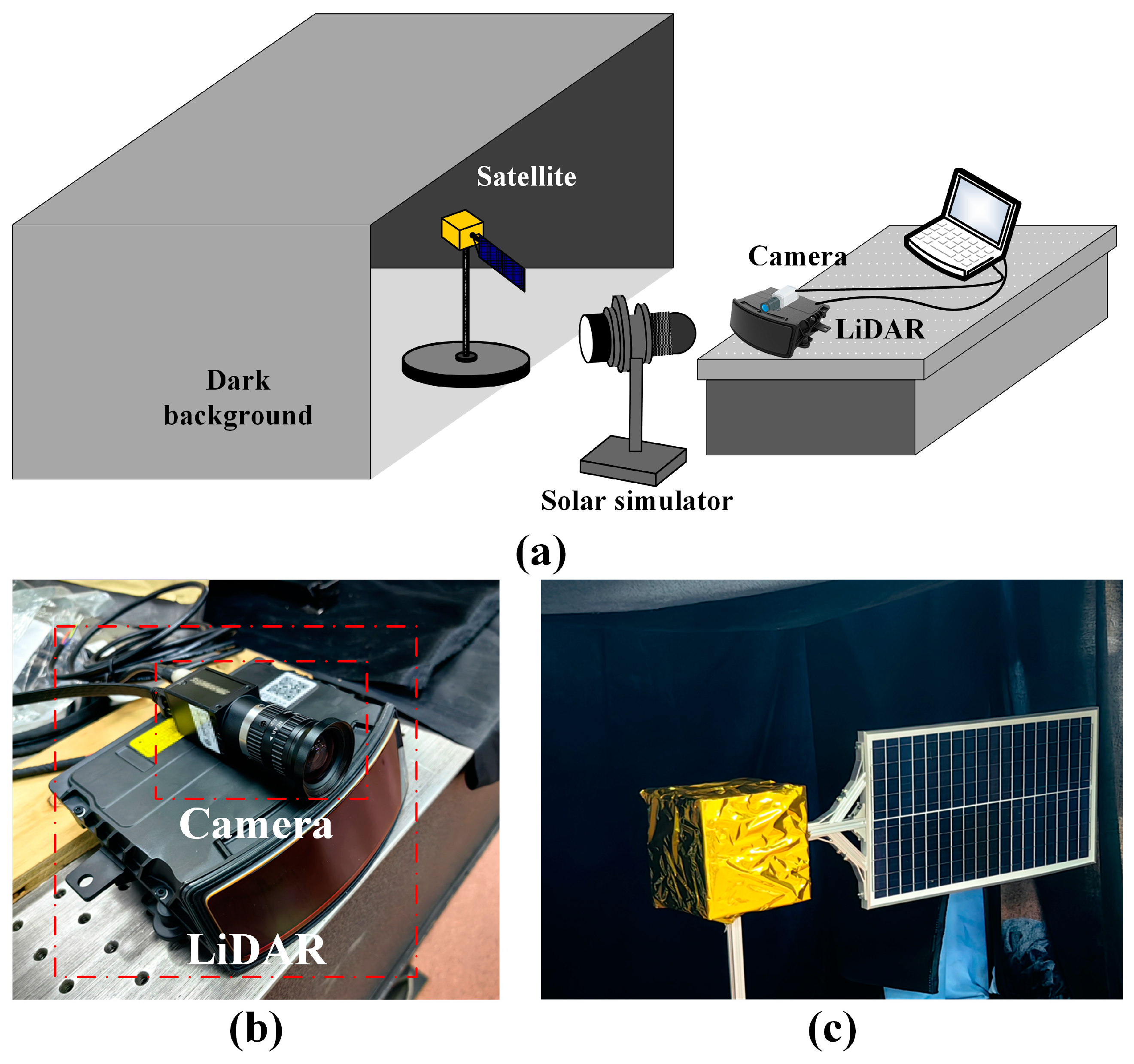
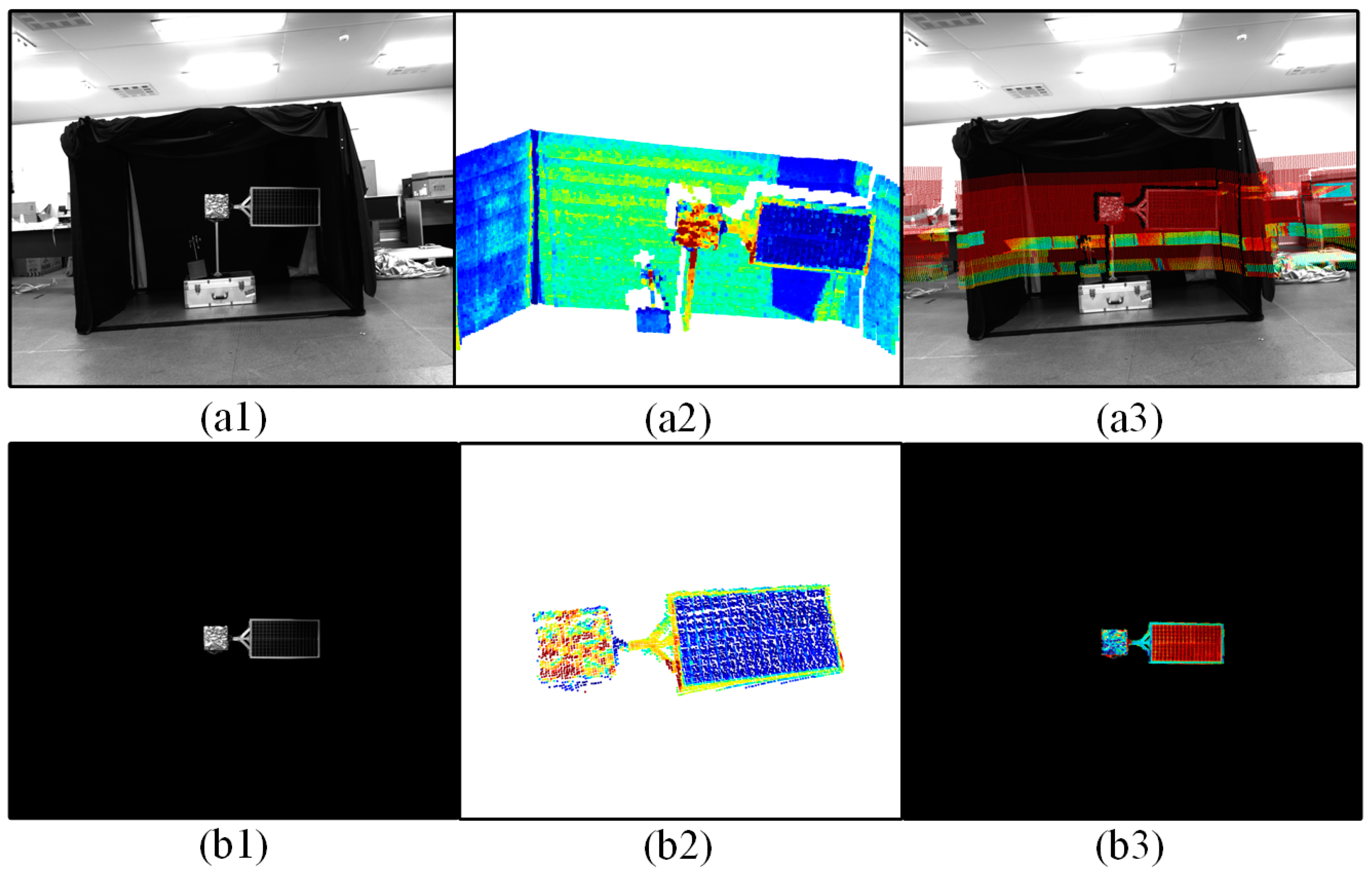
The method’s practicality was validated through a ground-based experiment using the measured data. The proposed approach achieves an MAE (R) of 0.97° and an MAE (t) of 0.015 m in real-world scenarios, demonstrating robust performance.
The organization of this paper is as follows: Section 2 introduces the proposed method, Section 3 presents the experimental results validating the effectiveness of the method, and Section 4 concludes the paper.

2. The Proposed Method

This paper proposes the point cloud and optical image feature collaborative pose estimation network (POCPE-Net). The overall network architecture of the proposed method is shown in Figure 2.
The input to the network consists of two frames of point cloud positions X R N 1 × 3 , Y R N 2 × 3 and images I X , I Y . First, the point cloud feature descriptors F ˜ P X , F ˜ P Y and image feature descriptors F O X , F O Y are extracted separately. Using the attention mechanism of the Transformer, the fused feature-driven point cloud matching correspondences are obtained, and the matching matrix M i is derived through Sinkhorn normalization. Using weighted SVD to solve for the i-th iteration’s pose transformation { R i , t i } , the point cloud X undergoes an SE(3) transformation and enters the (i + 1)-th iteration. After the specified number of iterations, the final pose transformation { R , t } is output. This work builds upon several excellent existing methods, specifically reusing RPM-Net’s point cloud feature extractor and traditional ORB feature descriptors due to their superior feature representation and registration capabilities. Our key innovation lies in employing Transformer attention mechanisms to optimize feature fusion and collaboration, leveraging 3D point cloud-to-2D image feature correlations to enhance both the accuracy and robustness of point cloud matching, thereby improving pose estimation precision.

2.1. Feature Extraction
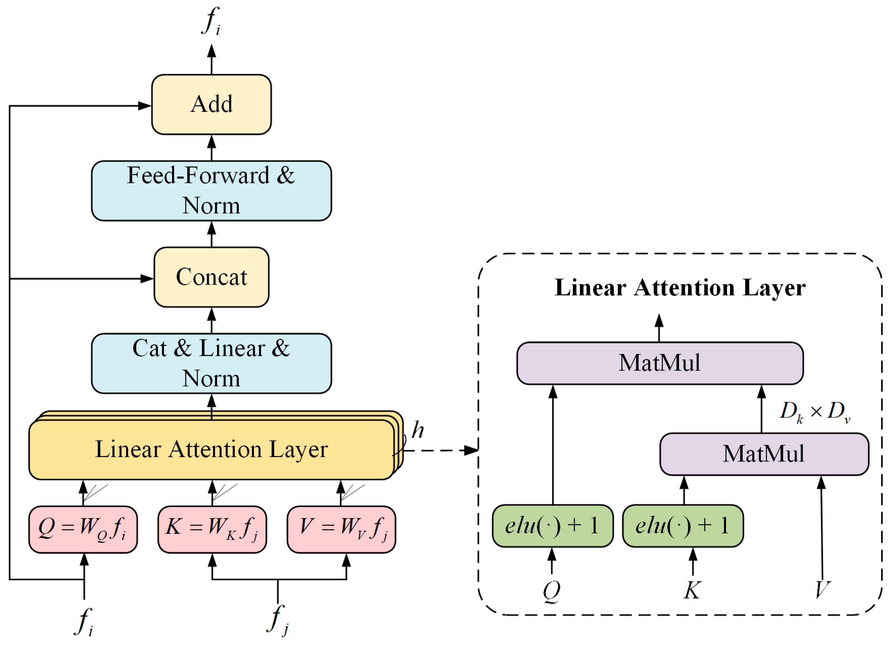
First, point cloud geometric feature descriptor F P is generated following the method described in [27]. The geometric feature descriptor of a single point x C is shown in Equations (1) and (2).
F P x C = [ x C , { Δ x C , i } , { PPF ( x C , x i ) } ] , x i N ˜ ( x C )
N ˜ ( x C ) = { x 1 , x 2 , , x k }
where Δ x C , i represents the vector differences between the point cloud and the positions of its i-th neighbors, N ˜ ( x C ) represents the set of k neighbors of x C , and PPF ( x C , x i ) are 4D point pair features (PPFs) [28] defined by Equation (3).
PPF ( x C , x i ) = [ ( n C , Δ x C , i ) , ( n i , Δ x C , i ) ,   ( n C , n i ) , Δ x C , i 2 ]
where n C and n i are the normal vectors of points x C and x i , respectively, which can be estimated using neighboring points. denotes the angle between vectors.
Using the feature extraction module shown in Figure 3, the point cloud geometric feature descriptors F P are refined into the point cloud feature descriptors F ˜ P with dimensions N × C , N = N 1 , N 2 . Based on the transformation relationships T I X and T I Y between the point cloud and the image coordinate system, the corresponding pixel points in I X and I Y are selected, and the 32-dimensional ORB [26] feature descriptors F O for each pixel are computed. The ORB feature descriptor combines the FAST keypoint detector and the BRIEF descriptor. The ORB feature descriptor is a 256-bit binary string which is divided into 32 bytes (8 bits per group) to obtain a 32-dimensional image feature descriptor F O . The point cloud feature descriptor [ F ˜ P X , F ˜ P Y ] is then concatenated with [ F O X , F O Y ] to generate fused features for both source and target point clouds with dimensions N 1 × ( C + 32 ) and N 2 × ( C + 32 ) , respectively. Taking the point cloud feature descriptor dimension C = 96 as an example, the two concatenated features form a 128-dimensional hybrid feature vector. The feature histogram of a single point is shown in Figure 4.

2.2. Transformer

The Transformer structure primarily consists of self-attention and cross-attention layers, iterated N T times. The structure of the attention layer is shown in Figure 5. For self-attention layers, the input features f i = f j are the features of the same frame, representing the attention operation of the features on themselves. For cross-attention layers, f i and f j represent the features of different frames (the order depends on the direction of the cross-attention). The input vectors of the attention layer are typically referred to as queries, keys, and values. The attention weights are calculated based on the dot product of the query vector Q with the corresponding key vector K for each value V. Information is retrieved from the value vector V according to the attention weights computed from the dot product of Q and each corresponding key vector K, where softmax denotes the normalized exponential function that converts the dot products into probability distributions. Formally, the attention layer is represented by Equation (4). This study utilizes a modified Linear Transformer, as presented in [29], illustrated in Figure 5.
Attention ( Q , K , V ) = softmax ( Q K T ) V

2.3. Matching and Weighted SVD

Then, the Matching Matrix M is computed using the Sinkhorn normalization algorithm [30]. The input to Sinkhorn normalization is the initial confidence matrix derived from the weighted dot product of source point cloud features and target point cloud features. The Sinkhorn normalization algorithm iteratively adjusts the initial confidence matrix into a doubly stochastic matrix (where the sums of rows and columns are all 1) while preserving the structural information of the original matrix. This is achieved by minimizing an objective function with an additional entropy term. Based on the Sinkhorn-normalized matrix, virtual correspondence points are computed in Equations (5) and (6).
M = Sinkorn ( 1 τ F Trans X , F Trans Y )
y ^ j = k = 1 N 2 M j k y k , ( j = 0 , N 1 , k = 0 , N 2 )
where y k is the kth point in the target point cloud and y ^ j is the virtual matching point corresponding to the j-th point in the source point cloud.
Finally, the pose transformation matrix is solved using weighted SVD, as shown in Equation (7).
R , t = argmin R , t j = 1 N 2 ω j R x j + t y ^ j 2
where ω j is the weight of the matching point pair { x j , y ^ j } , defined as ω j = j N 2 M j k .
The loss function of the network refers to [27] and consists of two parts, L T and L M , as shown in Equations (8)–(10). Here, R g t represents the rotation matrix label between the source point cloud and the target point cloud, and R denotes the predicted rotation matrix. Similarly, t g t represents the translation vector label between the source point cloud and the target point cloud, while t denotes the predicted translation vector. In this paper, following the empirical findings from Reference [27], λ is set to 0.01 to reduce training difficulty of the network.
L T = 1 N 2 j N 2 ( R g t x j + t g t ) ( R x j + t )
L M = 1 N 1 j N 1 k N 2 M j k 1 N 1 k N 2 j N 1 M j k
L = L T + λ L M

3. Experiments

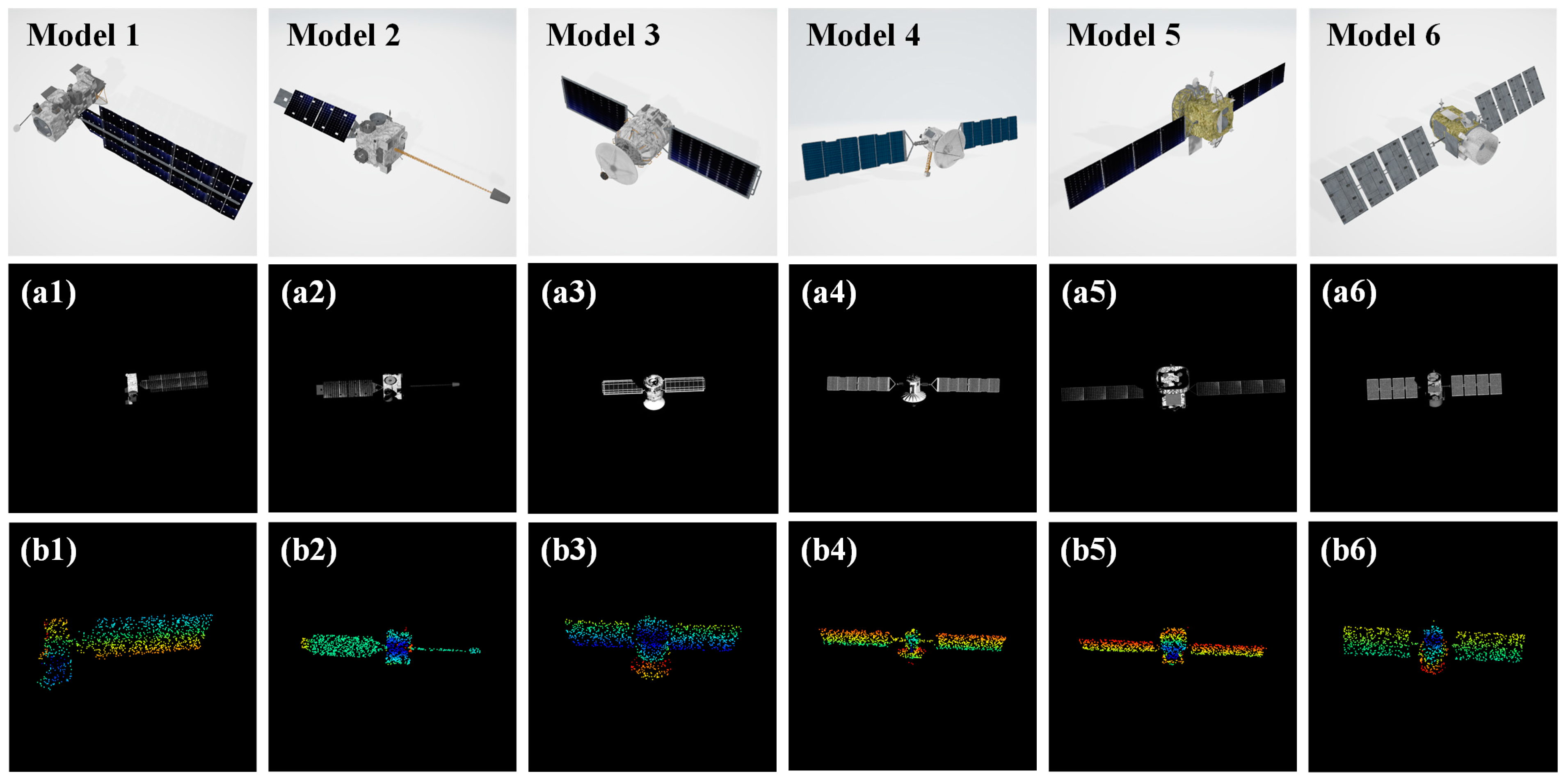
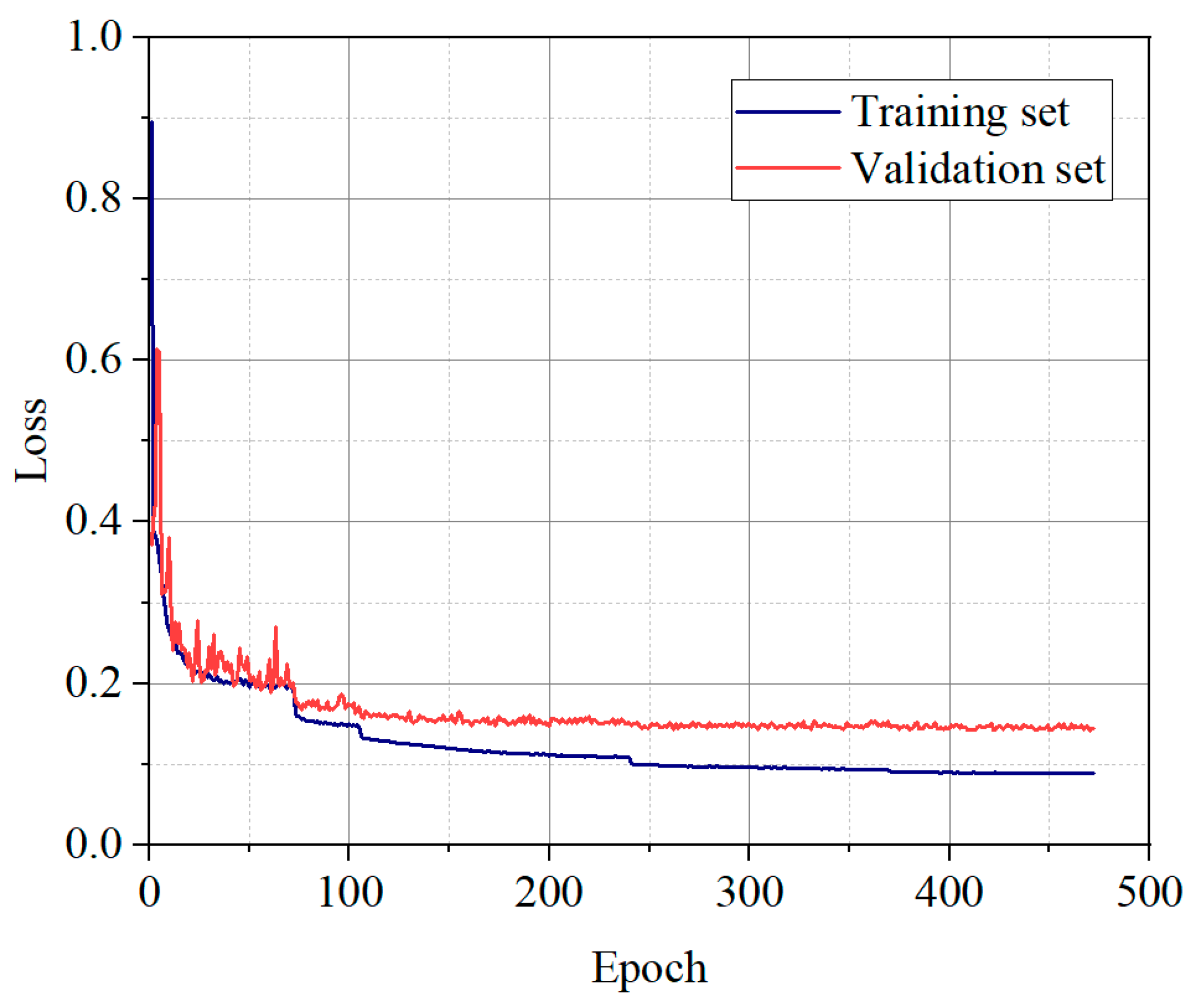
3.1. Dataset and Experimental Setup

Training the proposed method requires a large amount of registered point cloud and image data of spacecraft, which existing public datasets cannot meet. To construct the dataset, we collected 93 satellite CAD models and used the ray tracing method to simulate optical images and depth maps, generating corresponding point clouds from various viewpoints. The model sizes are randomly distributed between 2 m and 8 m. When generating simulated point clouds from depth maps, the depth data were preserved with millimeter-level precision. Some examples of the CAD model optical images and point cloud data are shown in Figure 6. For each model, we generated a sequence of 90 frames of data under fly-around observations, with the orbit shown in Figure 7. To ensure the network’s generalization capability, in each sequence, the target is assigned a random initial rotation within the range of three axes [0, 90°]. Additionally, for each frame, random rotations of [0.75°, 1.25°] and random translations of [0, 0.5 m] are applied relative to the previous frame. Additionally, we randomly added noise, which is sampled from N(0, 0.01 m), and clipped to the range [−0.05, 0.05] on each axis. We selected the current frame and the 5th subsequent frame to form a pair of point clouds. Finally, we selected simulation data from 60 models as the training set and data from 33 models as the validation set, resulting in 6300 training and 2700 validation data points.
Some hyperparameters in the network include the following: the number of point cloud neighbors set to 64, the dimension of the point cloud feature descriptors set to 96, Transformer iterations set to 3, and the pose iteration count set to 3. The point clouds were downsampled to 1024 × 3. The optimizer employed during the training process of the network is “Adam”, with an initial learning rate parameter set to 0.001. The batch size of the training is 8. The criterion for stopping training is reaching 500 epochs or the scheduler’s learning rate falling below 10−7.
To evaluate the performance, we use the anisotropic mean absolute error (MAE(R), MAE(t)) and the isotropic errors (Error(R), Error(t)) [27] as the quantitative evaluation metrics. Among them, the definition of anisotropic errors is given in Equations (11) and (12), and the definition of isotropic errors is provided in Equations (13) and (14). In Equations (11)–(14), Euler z y x denotes the Euler angles in the Z-Y-X rotation sequence, tr ( ) represents the trace of a matrix, the ground-truth translation vector is labeled as t g t = ( t g x , t g y , t g z ) , and the predicted translation vector is labeled as t = ( t x , t y , t z ) .
MAE R = 1 3 i = 1 3 Euler z y x R g t Euler z y x R
MAE t = 1 3 ( t g x t x + t g y t y + t g z t z )
Error R = arccos tr R g t 1 R 1 2
Error t = ( t g x t x ) 2 + ( t g y t y ) 2 + ( t g z t z ) 2
The training process visualization of the proposed network is illustrated in Figure 8.

3.2. Experimental Results and Analysis

We compared our method with several traditional methods, including ICP [14], FGR [31], SAC-IA [32], and SAC-IA + ICP, as well as several learning-based methods, including PointNetLK [33], IDAM [24], and RPM-Net [27]. Figure 9 shows some visualization results of point cloud registration from our method. The matching results in the figure visually demonstrate the accuracy of the proposed method. The quantitative results in Table 2 demonstrate that the proposed method achieves state-of-the-art performance, with a mean angular error (MAE) of 0.84° in rotation (R) and 0.022 m in translation (t), as well as an isotropic error of 1.72° in rotation (Error (R)) and 0.045 m in translation (Error (t)). Compared to single-modality point cloud-based methods, our multi-modal feature fusion approach significantly improves estimation accuracy. Specifically, traditional geometric methods (e.g., ICP and FGR) are limited by their sensitivity to initial values and reliance on parameter tuning. Among deep learning methods, our approach builds upon RPM-Net’s robust feature extraction framework and further enhances pose estimation by introducing an image feature collaboration mechanism and transformer attention module. The largest performance gap occurs in rotation estimation, where our method reduces RPM-Net’s error by 7.7%, attributed to the transformer’s ability to refine cross-modal feature correlations. Additionally, our method maintains computational efficiency, outperforming most traditional methods in speed while remaining competitive with advanced deep learning approaches.
During training, the frame interval between the source point cloud and the target point cloud was set to five frames. However, in practical applications, the frame interval may vary, with larger intervals indicating greater differences between the source and target point clouds. To investigate the performance of the proposed method under different frame intervals, we conducted comparative experiments with varying frame intervals. The experimental results are shown in Figure 10. The left vertical axis of Figure 10 corresponds to MAE (R), while the right vertical axis corresponds to MAE (t). The results indicate that as the frame interval increases, both rotation and translation estimation results degrade, with rotation estimation deteriorating more rapidly. This may be because image feature descriptors perform well when the rotation range is small, effectively guiding point cloud matching. However, for large rotation angles, the guidance provided by the image features weakens, leading to a decline in point cloud matching accuracy. The above robustness analysis reveals the method’s stability boundaries within a 30-frame interval. For large-scale scenarios, future improvements could incorporate distributed optimization algorithms to enhance the pose estimation method [34,35].

3.3. Ablation Studies
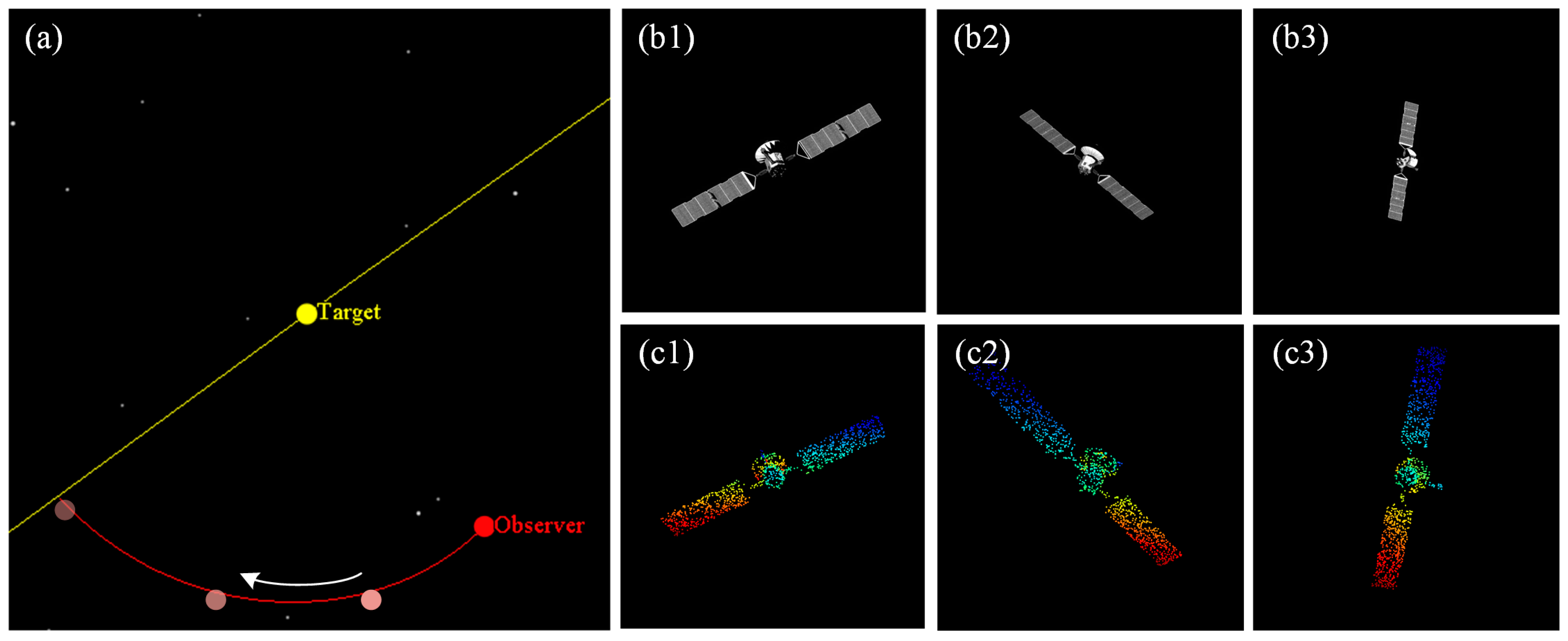
To verify the effectiveness of incorporating ORB features and the Transformer structure, ablation experiments were conducted, with the results shown in Table 3. The quantitative results show that the Transformer’s attention mechanism significantly improves accuracy, indicating its superior ability to extract the matching relationships of collaborative features compared to conventional methods, such as brute-force feature matching based on Euclidean distance. Moreover, the introduction of ORB feature descriptors enables using image feature matching relationships to partially supervise the point cloud matching results, further enhancing matching accuracy. The results demonstrate that adding ORB features and the Transformer structure has a positive impact on improving point cloud matching accuracy.

3.4. Validation

To validate the practical application value of the proposed method, we constructed a ground-testing environment. The experimental setup is shown in Figure 11.
We fastened the LiDAR and camera equipment to ensure a stable pairing between point clouds and optical images and varied the satellite model’s pose for measurements.
Measurements were conducted by varying the pose of the satellite model. The experimental preprocessing included the following: (1) Acquiring multiple checkerboard calibration images to obtain the camera intrinsic matrix using the calibration method. (2) Determining the extrinsic matrix of the LiDAR–camera system via the Perspective-n-Point (PnP) algorithm to establish ground truth. (3) After background filtering of the raw data (as shown in Figure 12), clean target foreground point cloud image sequences were obtained (with continuous frame processing results presented in Figure 13).
The inter-frame pose transformations were predicted using the proposed method, and the point cloud matching results are shown in Figure 14. Since traditional methods are overly dependent on initial values and exhibit unstable accuracy, we compare our approach only with learning-based methods. The quantitative evaluation results are presented in Table 4, demonstrating that the proposed method also maintains high accuracy on real measurement data.

4. Conclusions

To address the accuracy degradation of existing pose estimation methods in noncooperative target scenarios, this paper proposes a novel spacecraft pose estimation method based on the synergy of point cloud and optical image features. The method integrates ORB feature descriptors with point cloud feature descriptors, aiming to reduce point cloud mismatches under the guidance of a transformer mechanism, thereby improving pose estimation accuracy. Comparative experiments conducted on a point cloud–optical image dataset demonstrate that our method achieves superior performance, with a mean angular error (MAE) of 0.84° in rotation (R) and 0.022 m in translation (t) on the validation set, outperforming existing point cloud registration methods. Robustness analysis reveals the method’s stability boundaries within a 30-frame interval. Ablation studies validate the effectiveness of both ORB features and the transformer layer. Ground validation platform tests confirm the method’s practical applicability, offering a new solution for enhancing pose estimation accuracy of noncooperative space targets. By fusing optical and point cloud features, this work advances LiDAR–camera joint measurement techniques and supports on-orbit servicing missions. Due to the prerequisite of point cloud and image data pre-registration, future research could further investigate multi-source data alignment and fusion methods, along with comprehensive error analysis.

Author Contributions

Conceptualization, H.W.; Formal analysis, Q.N.; Funding acquisition, H.W.; Investigation, Q.N., Z.Y. and Z.W.; Methodology, Q.N.; Project administration, H.W.; Software, Q.N.; Supervision, H.W.; Validation, Q.N., Z.Y. and Y.L.; Visualization, Q.N., Z.Y. and Z.W.; Writing—original draft, Q.N.; Writing—review and editing, Q.N. All authors have read and agreed to the published version of the manuscript.

Funding

This research was funded by the National Natural Science Foundation of China, grant number 61705220.

Data Availability Statement

Not applicable.

Conflicts of Interest

The authors declare no conflicts of interest.

References

  1. Amaya-Mejía, L.M.; Ghita, M.; Dentler, J.; Olivares-Mendez, M.; Martinez, C. Visual Servoing for Robotic On-Orbit Servicing: A Survey. In Proceedings of the 2024 International Conference on Space Robotics (iSpaRo), Luxembourg, 24–27 June 2024; IEEE: Piscataway, NJ, USA, 2024; pp. 178–185. [Google Scholar]
  2. Ma, B.; Jiang, Z.; Liu, Y.; Xie, Z. Advances in space robots for on-orbit servicing: A comprehen-sive review. Adv. Intell. Syst. 2023, 5, 2200397. [Google Scholar] [CrossRef]
  3. Bigdeli, M.; Srivastava, R.; Scaraggi, M. Mechanics of Space Debris Removal: A Review. Aerospace 2025, 12, 277. [Google Scholar] [CrossRef]
  4. Bianchi, C.; Niccolai, L.; Mengali, G.; Ceriotti, M. Preliminary design of a space debris removal mission in LEO using a solar sail. Adv. Space Res. 2024, 73, 4254–4268. [Google Scholar]
  5. Nistér, D. An efficient solution to the five-point relative pose problem. IEEE Trans. Pat-Tern Anal. Mach. Intell. 2004, 26, 756–770. [Google Scholar]
  6. Zheng, Y.; Sugimoto, S.; Okutomi, M. A practical rank-constrained eight-point algorithm for fundamental matrix estimation. In Proceedings of the IEEE Conference on Computer Vision and Pattern Recognition, Portland, OR, USA, 23–28 June 2013; pp. 1546–1553. [Google Scholar]
  7. Wang, Y.; Zhang, Z.; Huang, Y.; Su, Y. High Precision Pose Estimation for Uncooperative Targets Based on Monocular Vision and 1D Laser Fusion. J. Astronaut. Sci. 2024, 71, 43. [Google Scholar]
  8. Duba, P.K.; Mannam, N.P.B. Stereo vision based object detection for autonomous navigation in space environments. Acta Astronaut. 2024, 218, 326–329. [Google Scholar] [CrossRef]
  9. Mu, J.; Li, S.; Xin, M. Circular-feature-based pose estimation of noncooperative satellite using time-of-flight sensor. J. Guid. Control. Dyn. 2024, 47, 840–856. [Google Scholar] [CrossRef]
  10. Renaut, L.; Frei, H.; Nüchter, A. Deep learning on 3D point clouds for fast pose estimation during satellite rendezvous. Acta Astronaut. 2025, 232, 231–243. [Google Scholar]
  11. Augenstein, S.; Rock, S. Simultaneous Estimaton of Target Pose and 3-D Shape Using the FastSLAM Algorithm. In Proceedings of the AIAA Guidance, Navigation, and Control Conference, Chicago, IL, USA, 10–13 August 2009; p. 5782. [Google Scholar]
  12. Mur-Artal, R.; Montiel, J.M.M.; Tardos, J.D. ORB-SLAM: A versatile and accurate monocular SLAM system. IEEE Trans. Robot. 2015, 31, 1147–1163. [Google Scholar]
  13. Jiang, L.; Tang, X.; Li, X.; He, X. Improved ORB-SLAM algorithm with deblurring image. In Proceedings of the 2024 4th International Conference on Electrical Engineering and Control Science (IC2ECS), Nanjing, China, 27–29 December 2024; IEEE: Piscataway, NJ, USA, 2024; pp. 770–774. [Google Scholar]
  14. Besl, P.J.; McKay, N.D. Method for registra-tion of 3-D shapes. In Proceedings of the Sensor Fusion IV: Control Paradigms and Data Structures, Boston, MA, USA, 15 December 1991; SPIE: Bellingham, WA, USA, 1992; pp. 586–606. [Google Scholar]
  15. Wang, Q.; Lei, T.; Liu, X.; Cai, G.; Yang, Y.; Jiang, L.; Yu, Z. Pose estimation of non-cooperative target coated with MLI. IEEE Access 2019, 7, 153958–153968. [Google Scholar] [CrossRef]
  16. Chen, Z.; Li, L.; Wu, Y.; Hua, B.; Niu, K. A new pose estimation method for non-cooperative spacecraft based on point cloud. Int. J. Intell. Comput. Cybern. 2019, 12, 23–41. [Google Scholar] [CrossRef]
  17. Hu, J.; Li, S.; Xin, M. Real-time pose determination of ultra-close non-cooperative satellite based on time-of-flight camera. IEEE Trans. Aerosp. Electron. Syst. 2024, 60, 8239–8254. [Google Scholar]
  18. Zhang, H.; Zhang, Y.; Feng, Q.; Zhang, K. Research on Unknown Space Target Pose Estimation Method Based on Point Cloud. IEEE Access 2024, 12, 149381–149390. [Google Scholar] [CrossRef]
  19. Zhu, Y.; Jin, R.; Lou, T.S.; Zhao, L. PLD-VINS: RGBD visual-inertial SLAM with point and line features. Aerosp. Sci. Technol. 2021, 119, 107185. [Google Scholar] [CrossRef]
  20. He, Y.; Liang, B.; He, J.; Li, S. Non-cooperative spacecraft pose tracking based on point cloud feature. Acta Astronaut. 2017, 139, 213–221. [Google Scholar]
  21. Zhu, A.; Yang, J.; Cao, Z.; Wang, L.; Gu, Y. Pose estimation for non-cooperative targets using 3D feature correspondences grouped via local and global constraints. In Proceedings of the MIPPR 2019: Pattern Recognition and Computer Vision, Wuhan, China, 2–3 November 2019. [Google Scholar]
  22. Gao, X.; Liao, Y.; Zhou, H. Pose Estimation and Simulation of Non-Cooperative Spacecraft Based on Feature Points Detection. In Proceedings of the 2024 IEEE 25th China Conference on System Simulation Technology and its Application (CCSSTA), Tianjin, China, 21–23 July 2024; IEEE: Piscataway, NJ, USA, 2024; pp. 12–16. [Google Scholar]
  23. Wang, Y.; Sun, Y.; Liu, Z.; Sarma, S.E.; Bronstein, M.M.; Solomon, J.M. Dynamic graph CNN for learning on point clouds. ACM Trans. Graph. 2019, 38, 1–12. [Google Scholar] [CrossRef]
  24. Li, J.; Zhang, C.; Xu, Z.; Zhou, H.; Zhang, C. Iterative distance-aware similarity matrix convolution with mutual-supervised point elimination for efficient point cloud registration. In Proceedings of the Computer Vision–ECCV 2020: 16th European Conference, Glasgow, UK, 23–28 August 2020; pp. 378–394. [Google Scholar]
  25. Jin, S.; Li, Y.; Wang, Z.; Huang, W.; Li, M. Nested Transformer for Fast and Robust Point Cloud Registration. In Proceedings of the 2024 IEEE 6th Advanced Information Management, Communicates, Electronic and Automation Control Conference (IMCEC), Chongqing, China, 24–26 May 2024; IEEE: Piscataway, NJ, USA, 2024; Volume 6, pp. 788–794. [Google Scholar]
  26. Rublee, E.; Rabaud, V.; Konolige, K.; Bradski, G. ORB: An efficient alternative to SIFT or SURF. In Proceedings of the 2011 International Conference on Computer Vision, Barcelona, Spain, 6–13 November 2011; pp. 2564–2571. [Google Scholar]
  27. Yew, Z.J.; Lee, G.H. RPM-Net: Robust point matching using learned features. In Proceedings of the IEEE/CVF conference on computer vision and pattern recognition, Seattle, WA, USA, 13–19 June 2020; pp. 11824–11833. [Google Scholar]
  28. Deng, H.; Birdal, T.; Ilic, S. PPFNet: Global context aware local features for robust 3D point matching. In Proceedings of the IEEE Conference on Computer Vision and Pattern Recognition, Salt Lake City, UT, USA, 18–22 June 2018; pp. 195–205. [Google Scholar]
  29. Katharopoulos, A.; Pappas, V.N.; Fleuret, F. Transformers are RNNs: Fast autoregres-sive transformers with linear attention. In Proceedings of the International Conference on Machine Learning, Virtual, 13–18 July 2020; pp. 5156–5165. [Google Scholar]
  30. Pan, Y.; Yang, B.; Liang, F.; Dong, Z. Iterative global similarity points: A robust coarse-to-fine integration solution for pairwise 3D point cloud registration. In Proceedings of the 2018 International Conference on 3D Vision (3DV), Verona, Italy, 5–8 September 2018; pp. 180–189. [Google Scholar]
  31. Zhou, Q.-Y.; Park, J.; Koltun, V. Fast global registration. In Proceedings of the Computer Vision–ECCV 2016: 14th European Conference, Amsterdam, The Netherlands, 11–14 October 2016; pp. 766–782. [Google Scholar]
  32. Rusu, R.B.; Blodow, N.; Beetz, M. Fast point feature histograms (FPFH) for 3D registration. In Proceedings of the 2009 IEEE International Conference on Robotics And Automation, Kobe, Japan, 12–17 May 2009; pp. 3212–3217. [Google Scholar]
  33. Aoki, Y.; Goforth, H.; Srivatsan, R.A.; Lucey, S. PointNetLK: Robust efficient point cloud registration using pointnet. In Proceedings of the IEEE/CVF Conference on Computer Vision and Pattern Recognition, Long Beach, CA, USA, 15–20 June 2019; pp. 7163–7172. [Google Scholar]
  34. Liu, T.; Qin, Z.; Hong, Y.; Jiang, Z.-P. Distributed Optimization of Nonlinear Multiagent Systems: A Small-Gain Approach. IEEE Trans. Autom. Control. 2022, 67, 676–691. [Google Scholar] [CrossRef]
  35. Jin, Z.; Li, H.; Qin, Z.; Wang, Z. Gradient-Free Cooperative Source-Seeking of Quadrotor Under Disturbances and Communication Constraints. IEEE Trans. Ind. Electron. 2025, 72, 1969–1979. [Google Scholar]
Figure 1. Matching relationships of point clouds and images (arrows indicate matched points, and the same color denotes correct matches). (a) Point cloud mismatching. (b) Image matching.
Aerospace 12 00314 g001
Figure 2. Structure of the point cloud and optical image feature collaborative pose estimation network.
Aerospace 12 00314 g002
Figure 3. Point cloud feature extraction module.
Aerospace 12 00314 g003
Figure 4. Histogram of point cloud and image collaborative feature descriptors.
Aerospace 12 00314 g004
Figure 5. The attention layer architecture.
Aerospace 12 00314 g005
Figure 6. Examples of simulation results of different satellite models. (a1a6) Optical simulation images. (b1b6) Point clouds (colors are used to distinguish depth levels).
Aerospace 12 00314 g006
Figure 7. On-orbit conditions and partial sequence simulated images. (a) Relative motion trajectory in the target’s VVLH coordinate system (arrow indicates relative motion directions). (b1b3) The 8th, 33rd, and 58th frame optical images. (c1c3) The 8th, 33rd, and 58th frame point clouds (colors are used to distinguish depth levels).
Aerospace 12 00314 g007
Figure 8. Visualization of training process.
Aerospace 12 00314 g008
Figure 9. Partial results of point cloud matching (the green, blue, and red point clouds denote the source, target, and transformed source point clouds, respectively).
Aerospace 12 00314 g009
Figure 10. MAE (R) and MAE (t) changes at different frame intervals.
Aerospace 12 00314 g010
Figure 11. Ground-testing platform and equipment. (a) Schematic diagram of measurement scenario. (b) LiDAR and camera equipment. (c) Satellite scaling model.
Aerospace 12 00314 g011
Figure 12. Measurement data processing process (colors are used to distinguish depth levels). (a1a3) Optical images, point clouds, and registration results. (b1b3) Optical image, point cloud, and registration results with background interference removed.
Aerospace 12 00314 g012
Figure 13. Processed multi-frame data (colors are used to distinguish depth levels). (a1a5) Continuous frame optical image. (b1b5) Continuous frame point cloud.
Aerospace 12 00314 g013
Figure 14. Point cloud registration results of the proposed method based on measured data (the green, blue, and red point clouds denote the source, target, and transformed source point clouds, respectively).
Aerospace 12 00314 g014
Table 1. Classification of pose estimation methods for noncooperative spacecraft.
CategorySub-CategorySensorsKey Algorithms
Image-based methodsFeature extraction and matching [5,6]Monocular cameraEssential matrix solving
SLAM approaches [11,12,13]Monocular/Stereo cameraFast SLAM, ORB-SLAM
Point cloud-based methods ICP and ICP variants [14,15,16,17,18]Monocular/Stereo/TOF camera, LiDAREuclidean distance
Geometry-based methods [19,20,21]LiDAR/TOF cameraEuclidean distance, Normal vectors
Learning-based methods [22,23,24,25]LiDAR/TOF camera3D voxel CNN, Graph CNN, Transformer
Table 2. Quantitative results of different methods.
MethodMAE (Anisotropic)Error (Isotropic)Time (ms)
R/°t/mR/°t/m
ICP16.090.22737.480.45976
FGR2.470.0484.600.092680
SAC-IA2.080.0404.040.078257
SAC-IA + ICP1.590.0293.010.058447
PointNetLK12.220.47923.060.92866
IDAM1.410.0732.850.14627
RPM-Net0.910.0241.830.050106
Ours0.840.0221.720.04568
Table 3. Quantitative results of the POCPE-Net with different components.
MethodMAE (Anisotropic)Error (Isotropic)
R/°t/mR/°t/m
Baseline1.130.0582.280.115
Baseline + Trans0.860.0231.770.047
POCPE-Net (Baseline + Trans + ORB)0.840.0221.720.045
Table 4. Quantitative results of pose estimation based on measured data.
MethodMAE (Anisotropic)Error (Isotropic)
R/°t/mR/°t/m
PointNetLK14.790.06836.630.145
IDAM(GNN)3.660.1047.760.051
RPM-Net1.640.0203.390.039
POCPE-Net (ours)0.970.0151.770.028
Disclaimer/Publisher’s Note: The statements, opinions and data contained in all publications are solely those of the individual author(s) and contributor(s) and not of MDPI and/or the editor(s). MDPI and/or the editor(s) disclaim responsibility for any injury to people or property resulting from any ideas, methods, instructions or products referred to in the content.

