Article

A Preliminary Exploratory Study of the Flow and Heat Transfer Characteristics of Fuel Elements in Low-Enriched Uranium Cores

Space Engineering University, 1 Bayi Road, Beijing 101416, China
*
Author to whom correspondence should be addressed.
Aerospace 2025, 12(4), 290; https://doi.org/10.3390/aerospace12040290
Submission received: 15 February 2025 / Revised: 25 March 2025 / Accepted: 26 March 2025 / Published: 30 March 2025
(This article belongs to the Section Astronautics & Space Science)

Abstract

:
Nuclear thermal propulsion, which uses a reactor core as the energy source of a nuclear thermal rocket, is expected to become an effective means of deep space exploration in the future. The reactor core can be damaged by a large temperature gradient. Thus, investigating the structural distribution of its internal components and understanding its flow and heat transfer characteristics is highly important. In this study, a 19-hole hollow hexagonal prism fuel element is selected for simulation. A new type of fuel element is proposed by changing the diameter of the channels in the work material, and the heat transfer characteristics are compared and analyzed. Compared with a conventional fuel element under uniform inlet conditions, when the inlet conditions and the diameter of the channel in the work material are changed, the peak temperature inside the fuel element decreases, but the overall temperature distribution is more uniform. Along the flow direction, the temperature distribution boundary is located at y = 300–500 mm. From the inlet to this position, the temperature distribution on the axial cross-section is uniform. From this position to the outlet, the temperature difference along the radial cross-section is significantly reduced, and the temperature fluctuation at the periphery of the fuel element is significantly improved. The research results can provide a reference for the design of fuel elements.

1. Introduction

Since the 1950s, when the U.S. and the Soviet Union/Russia started their nuclear power propulsion research, several core fuel element schemes have been developed, evolved, and tested in nuclear thermal propulsion research programs. Typical fuel element configurations include hexagonal graphite-based fuel elements [1], twisted strip fuel elements [2], hexagonal ceramic-on-metal fuel elements (CERMET) [3], spherical encapsulated particulate fuel elements [4], miniature reactor engine (MITEE)-type fuel elements [5], square lattice honeycomb (SLHC)-type fuel elements [6], and grooved ring-type fuel elements [7].
A comparative analysis of fuel element designs reveals those early proposals predominantly featured axial-flow channels within porous prismatic structures, offering advantages such as geometrically regular configurations, simplified flow paths, and ease of manufacturing. However, their heat transfer efficiency is inherently limited by the requirement to maintain structural strength, which restricts the density of cooling channels. Subsequent developments introduced radial-flow channels and porous media-type fuel elements, characterized by more intricate flow paths that provide a high specific surface area for heat transfer and reduced flow pressure drop. Nevertheless, the shortened radial conduction paths in these advanced designs generate steep temperature gradients, which may induce excessive thermal stresses capable of fracturing the fuel element and compromising its structural integrity [8]. The fuel element serves as the energy source of the reactor core, and its structural stability is a prerequisite for the reliable performance of nuclear thermal rocket engines. While later-developed fuel elements exhibit improved heat transfer efficiency, the steep temperature gradients in the radial direction can lead to structural failure, severely compromising reactor performance and even triggering nuclear fuel leakage, thereby risking nuclear safety incidents. In recent years, global efforts have focused on exploring fuel element configurations with superior performance. Existing research indicates that although axial-flow fuel elements possess a limited heat transfer capacity, their inherent advantages—stability, safety, and simplicity—remain critical considerations for space propulsion systems. Consequently, axial-flow fuel elements retain significant research value. The key challenge lies in enhancing the heat transfer efficiency of coolant channels within axial-flow fuel elements while ensuring structural integrity, which remains an urgent issue to address.
The unique characteristics of nuclear fuel introduce significant complexity to conducting related experiments. Numerical simulation methods are therefore employed to advance research in this field, offering effective guidance for practical applications. In nuclear thermal rocket engines, the propellant (hydrogen) is heated in the reactor core and then accelerated through the nozzle to generate thrust. To improve the heat transfer efficiency in the coolant channels of axial-flow fuel elements within nuclear thermal rocket engines, it is first necessary to clarify the engine’s overall operational conditions. This ensures a precise understanding of the working environment for the fuel elements. Belair [9] and Joyner [10] conducted overall performance simulations of a nuclear thermal rocket engine system. Duan performed a study on the reactor core, including neutron physics analyses under special conditions such as partial blockage, power variation, fuel element configurations, and moderator arrangements [11,12,13]. Furthermore, accurate thermophysical property parameters of the propellant are essential. Hess [14] and Fang [15] investigated hydrogen under extreme conditions to characterize its physical properties. Additionally, numerous scholars have conducted numerical investigations into the flow dynamics within fuel elements; for example, Wang [16] used numerical simulations to modify a turbulence model, enabling accurate corrections to the temperature distribution of hydrogen within a fuel element to match experimental data, thereby validating the model’s accuracy. Ai [17] and Li [18] analyzed the thermophysical properties inside fuel elements by adjusting boundary conditions. Ji [19] focused on a particle bed reactor (PBR) fuel element to study the flow behavior of the working fluid and analyze associated flow phenomena.
Few studies have analyzed heat transfer and flow characteristics within a nuclear thermal rocket engine by starting from a single fuel element, proposing targeted improvements, and then integrating these into a holistic analysis. This study selects a low-enriched uranium reactor core and adopts the 19-channel axial fuel element as the research object. Using numerical simulations, we systematically analyze the effects of structural parameter variations on flow and heat transfer characteristics. The findings provide valuable insights for guiding the design of reactor cores in nuclear thermal rockets.

2. Fuel Element Description

2.1. Fuel Element Coolant

Hydrogen is the gas with the lowest molecular weight and exhibits excellent thermal conductivity. In a nuclear thermal rocket engine, hydrogen is heated in the reactor core, then accelerated and expelled through the nozzle to generate thrust. Within the engine, hydrogen serves not only as the propellant for the propulsion system but also as the coolant for the reactor. The specific impulse ( I s p ) is a critical parameter characterizing rocket engine performance. A higher specific impulse indicates greater propellant efficiency. Considering the vacuum operating environment of nuclear thermal rocket engines, where the propellant pressure at the nozzle exit approaches zero, the expression for specific impulse is as follows:
I s p = 2 γ γ 1 R 0 m w T c
In Equation (1), γ = the specific heat ratio, R 0 = the universal gas constant, m w = the average molecular weight of the propellant, and T c = the propellant temperature in the reactor chamber.
In this equation, the specific impulse ( I s p ) is a function of temperature and the molecular weight of the propellant. As evident in the equation, a propellant with a low molecular weight ensures a high specific impulse for the rocket engine. Therefore, hydrogen was selected as the coolant for the fuel elements.

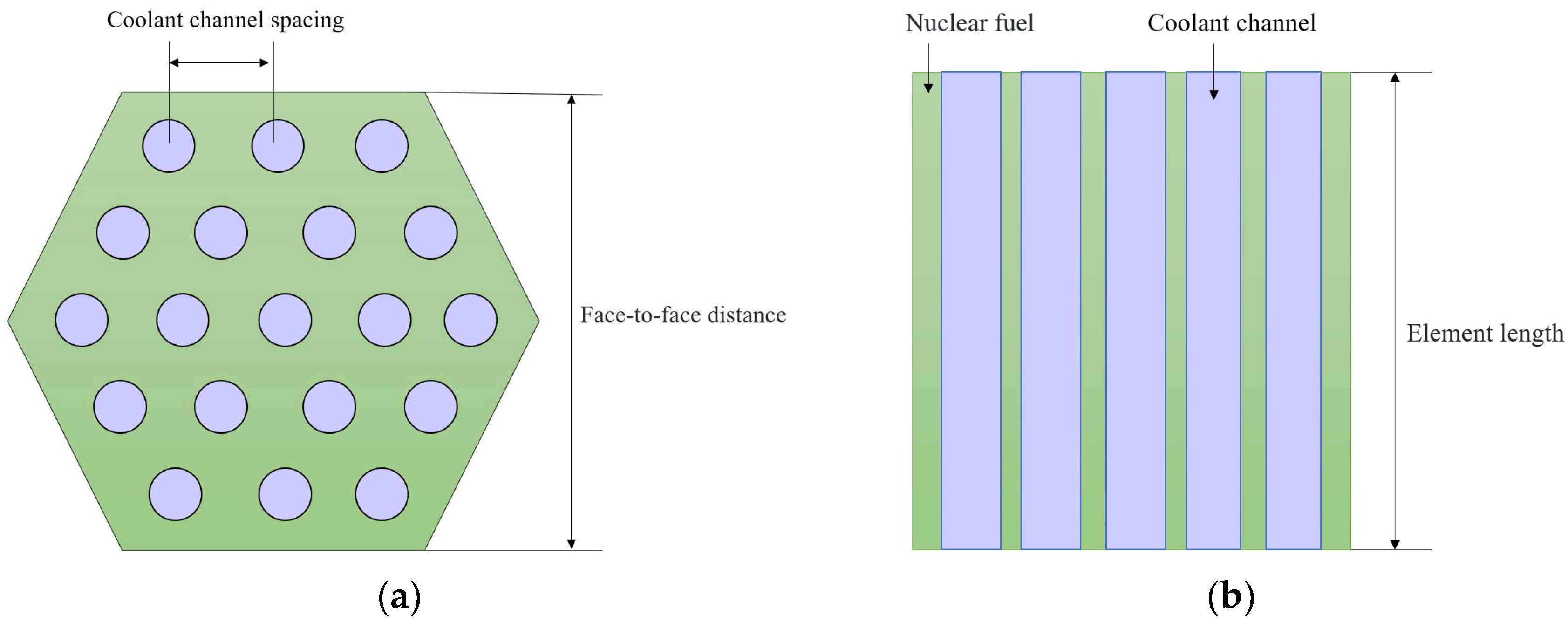
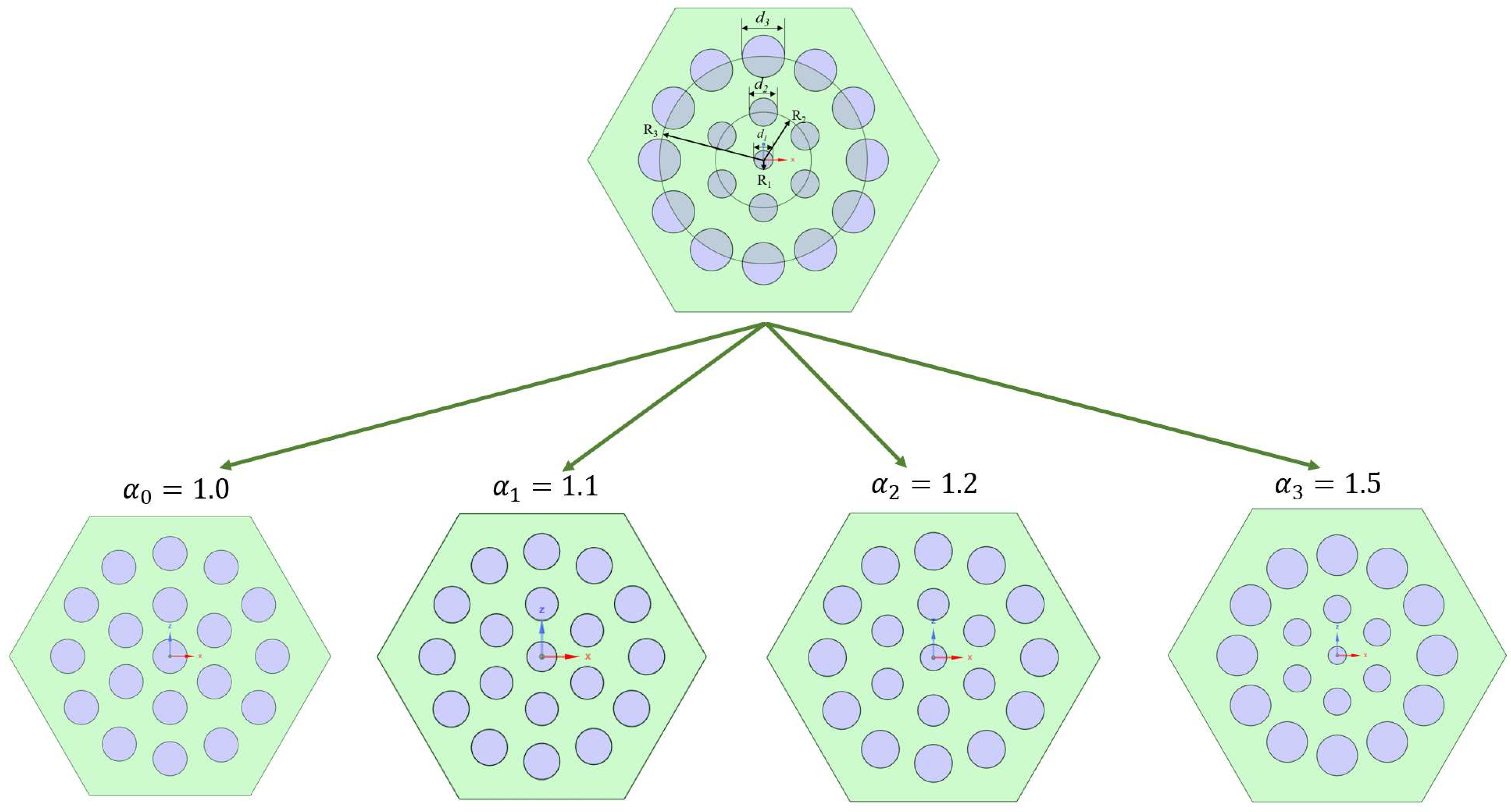
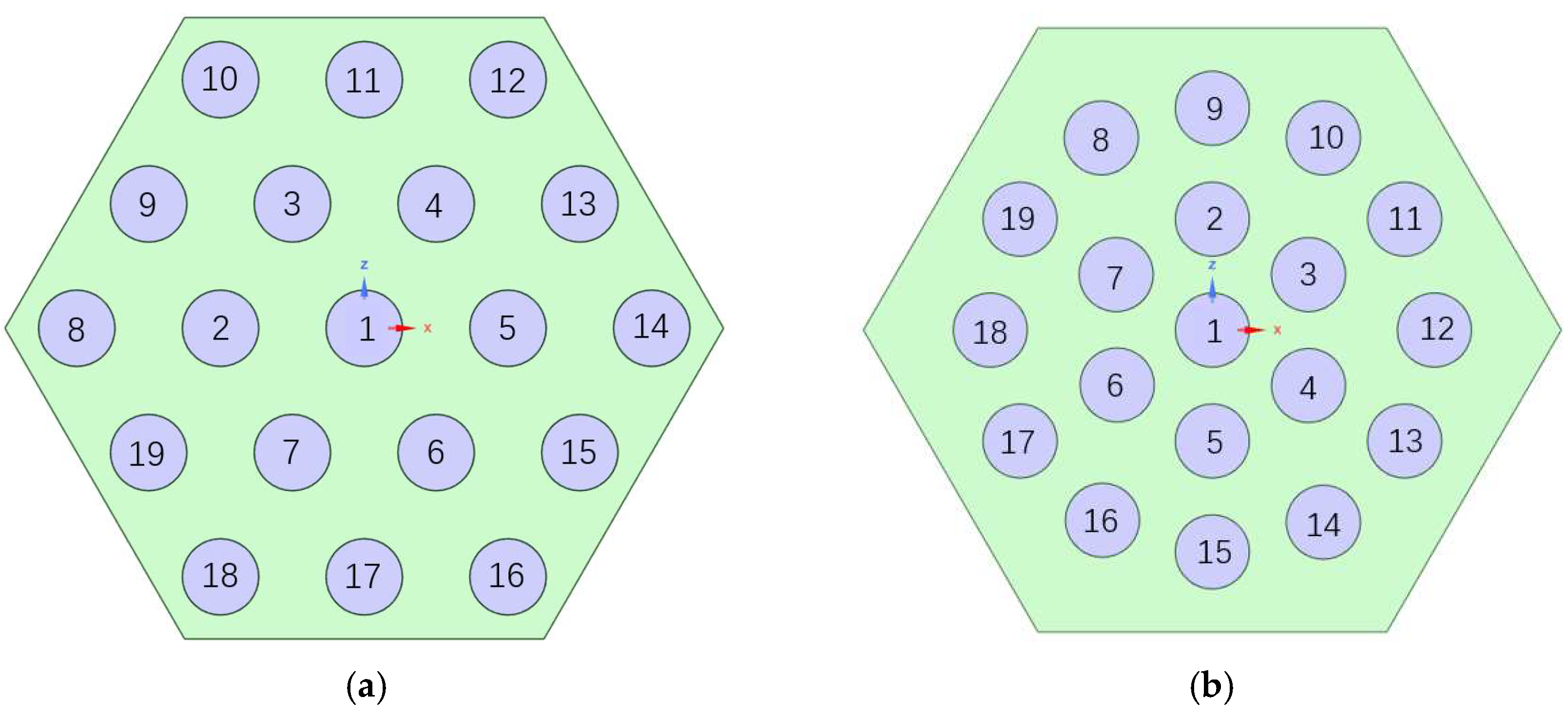
2.2. Fuel Element Geometric Model

Wang [16] employed the finite volume method to conduct a thermal–hydraulic analysis of nuclear thermal propulsion fuel elements. Building upon this reference, this study adopts an identical fuel element model. The fuel element features a regular hexagonal prism structure, with its radial and axial cross-sectional configurations illustrated in Figure 1a and b, respectively. In the diagrams, the green-filled regions represent nuclear fuel, while the lavender-colored regions denote coolant channels. Both the surfaces of the coolant channels and the outer walls of the hexagonal prism fuel element are coated with a ZrC (zirconium carbide) layer. This coating serves dual purposes: mitigating corrosion caused by hydrogen dissociation and enhancing heat transfer efficiency. Key structural parameters are summarized in Table 1.

3. Numerical Model

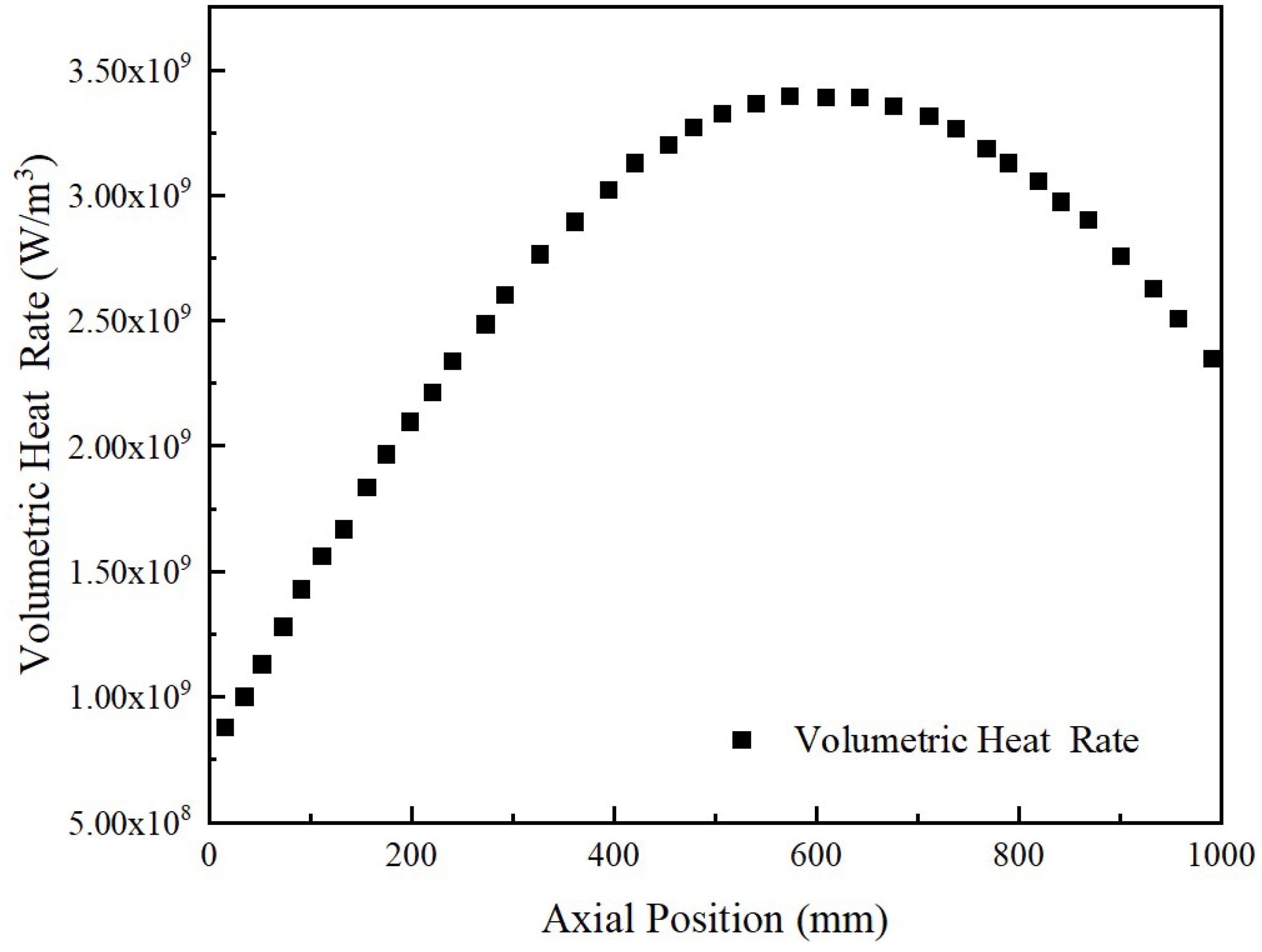
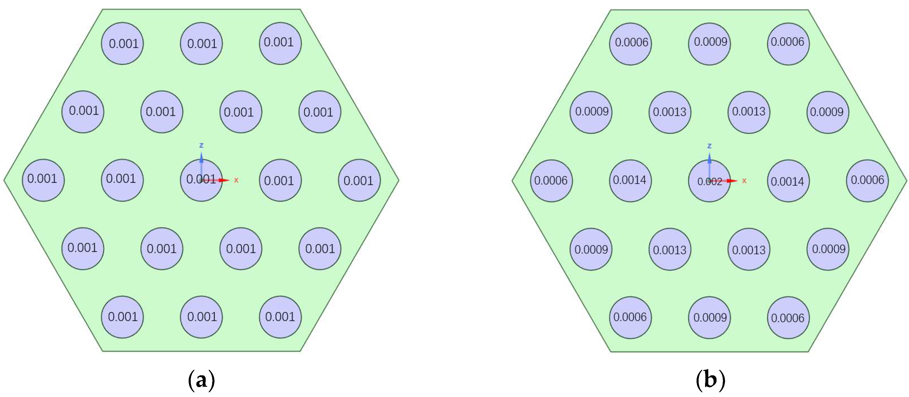
3.1. Boundary Condition Setting

This study uses the low-enriched uranium core with a Bullseye structure [20] for simulation analysis. The axial volumetric heat power distribution of the fuel elements is shown in Figure 2 below, exhibiting a parabolic distribution. The coolant inlet temperature is 127.8 K, and the mass flow rate of each fuel element is 0.019 kg/s.
The physical properties of the materials in various parts of the reactor core are an important basis for setting boundary conditions. The parameters of the primary coolant H2, such as density, specific heat, thermal conductivity, and viscosity, are set based on [21,22]. The nuclear fuel uses (U and Zr) C, with the density and thermal conductivity of the material referenced from [7]. The thermal conductivity of ZrC material is set based on [23], and the material property data from the literature are extracted and fitted.

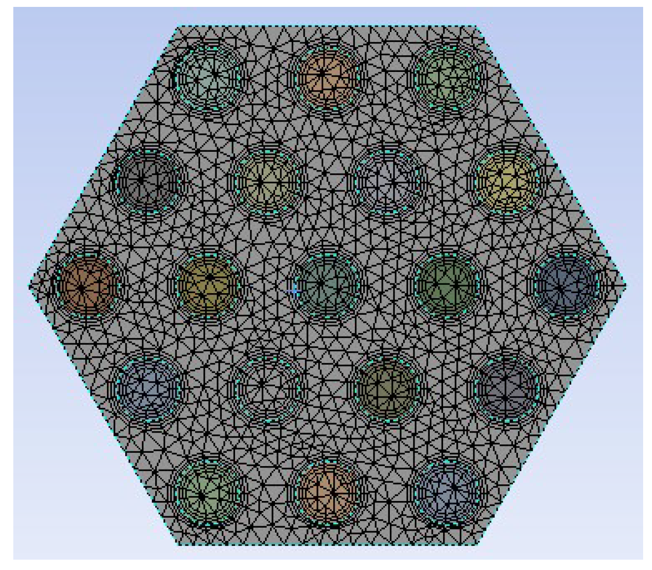
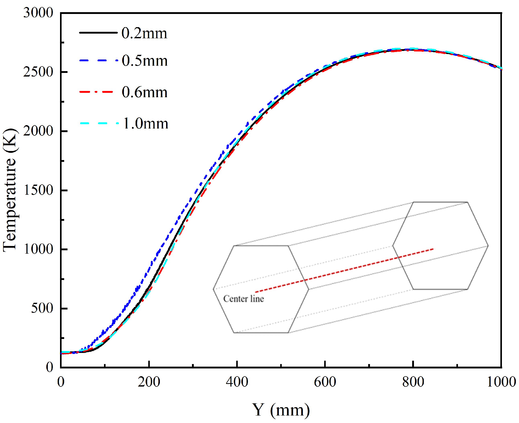
3.2. Mesh-Independent Verification

Combined with the actual situation, the axial length of the fuel element is much greater than the radial length, resulting in an overall elongated structure of the element. Moreover, the size of the fuel element itself is at the millimeter level, and the size of the coolant flow paths is even smaller. For accurate calculation, the grid size needs to be smaller than the diameter of the coolant channel to ensure grid quality and improve the accuracy of subsequent calculations. Figure 3 shows a schematic diagram of the grid division, and the information of the different grid sizes is shown below in Table 2.
The centerline temperature of the fuel element was extracted under different surface mesh sizes in the fluid domain. The extraction locations and temperature distributions are shown in Figure 4. Comparative analysis reveals that in the axial range of 0–300 mm, the temperature increase rate for the 0.5 mm mesh size is higher than other sizes. In the axial range of 300–500 mm, the temperature distribution trends under the four mesh sizes are nearly identical. In the axial range of 500–1000 mm, the temperature distributions gradually converge for all mesh sizes. Along the entire centerline, the 0.2 mm, 0.6 mm, and 1.0 mm meshes produced essentially overlapping temperature distributions. Considering both mesh quality and computational resources, the 0.6 mm surface mesh size in case 3 was selected as the basis for subsequent calculations.

3.3. Numerical Modeling

This study focused on the temperature distributions in both fluid and solid domains, aiming to understand the thermal profile of fuel elements and the temperature rise characteristics of internal coolant flows. As different turbulence models are applicable to distinct flow processes, this work systematically evaluates their suitability for simulating flow and heat transfer phenomena within the investigated fuel element. The analysis leverages experimental data from [16] to validate model performance.
Li et al. [18] employed the Realizable k-epsilon model to simulate flow patterns within fuel assemblies. Meanwhile, Ju et al. [24] conducted a comparative analysis of temperature and pressure distributions across fuel element cross-sections using three turbulence models: Standard k-epsilon, Realizable k-epsilon, and SST k-omega, ultimately selecting the SST k-omega model as their computational framework due to its superior accuracy in capturing complex flow–thermal interactions.
This study compared the temperature distributions at Station 1 (location is shown in Figure 5) within the fuel element using five turbulence models: Standard k-epsilon, Realizable k-epsilon, RNG k-epsilon, Standard k-omega, and SST k-omega. Axial temperature profiles at Station 1 under these models were extracted and compared with experimental data from the NRX-A6 tests under the NERVA project provided in [17], as illustrated in Figure 5. The results demonstrate that the SST k-omega + DO model, which accounts for radiation effects, significantly reduces deviations from experimental results, achieving an error margin of approximately 10%. Consequently, the SST k-omega + DO model was selected for subsequent simulations in this study.

3.4. Entrance Condition Design

The spacing between the coolant channels set in the literature is 4.4 mm. Based on the power distribution and heat transfer characteristics of the fuel element, the analysis results show that the temperature in the central region is significantly higher. Uneven temperature distribution can lead to uneven thermal stress distribution within the fuel element, which, in turn, can cause cracks or even severe damage to the fuel element structure. To solve this issue, the following three solutions were designed: (1) the first solution, based on the traditional coolant channel scheme, adjusts the inlet flow rate, i.e., non-uniform inlet conditions under equal-diameter channels; (2) the second solution, based on the traditional fuel element’s equal-diameter coolant channel distribution, only adjusts the position of the coolant channels within the fuel element, i.e., the equal-diameter structure in the new fuel element; (3) the third solution simultaneously adjusts the position and size of the coolant channels within the fuel element, i.e., the variable-diameter structure in the new fuel element.
Conventional fuel elements, as shown below in Figure 6, have the same coolant channel diameter, and the flow rate into the coolant channel is adjusted to divide it into uniform inlet and nonuniform inlet conditions.
Considering the higher temperature in the center region of the fuel element, to make full use of the heat source generated by the fuel element, the original coolant channel arrangement and diameter size were adjusted, as shown below in Figure 7 below, and the modified fuel element was defined as a new type of fuel element.
When the inlet mass flow rate of the fuel element is certain, the simulation results indicate that the temperature at the center position is the highest. Under the premise of ensuring that the area of the radial cross-section coolant channel of the fuel element remains unchanged, the growth multiplier is taken to be α i ( i = 0,1 , 2,3 ) , and the diameter of the coolant channel is gradually increased along the radial direction. The structure of the coolant channel is shown in Figure 7, and the detailed parameters are shown in Table 3. The diameter of the coolant channel in the R1 circle is d1, the diameter of the coolant channel in the R2 circle is d2, and the diameter of the coolant channel in the R3 circle is d3. The relationships among d1, d2, and d3 are as follows:
d 2 = α i d 1
d 3 = α i d 2
where α was 1.0, 1.1, 1.2, and 1.5 and used to analyze the temperature distribution within the new fuel element. Specific information is shown in Table 3.
In this study, simulation analysis was carried out for both conventional and new fuel elements, and the details of the entrance conditions are summarized in Table 4.

4. Results and Discussion

The inlet flow rate of the fuel element is 0.019 kg/s, evenly distributed among 19 coolant channels. Data from different cross-sections at 100, 300, 500, 700, and 900 mm from the inlet along the axial direction are taken. The temperature and velocity distribution contours are displayed visually on the cross-sections in Figure 8. It is observed that the temperature at the center of the fuel element is higher than that of the surrounding areas and gradually increases along the direction of hydrogen flow. By examining the velocity distribution corresponding to the fuel element, it is evident that the central flow velocity is significantly higher than the surrounding flow velocity along the direction of hydrogen flow. Additionally, the temperature and velocity near the inner corners of the hexagonal prism are relatively lower, while the temperature and flow velocity at the very center are relatively higher.

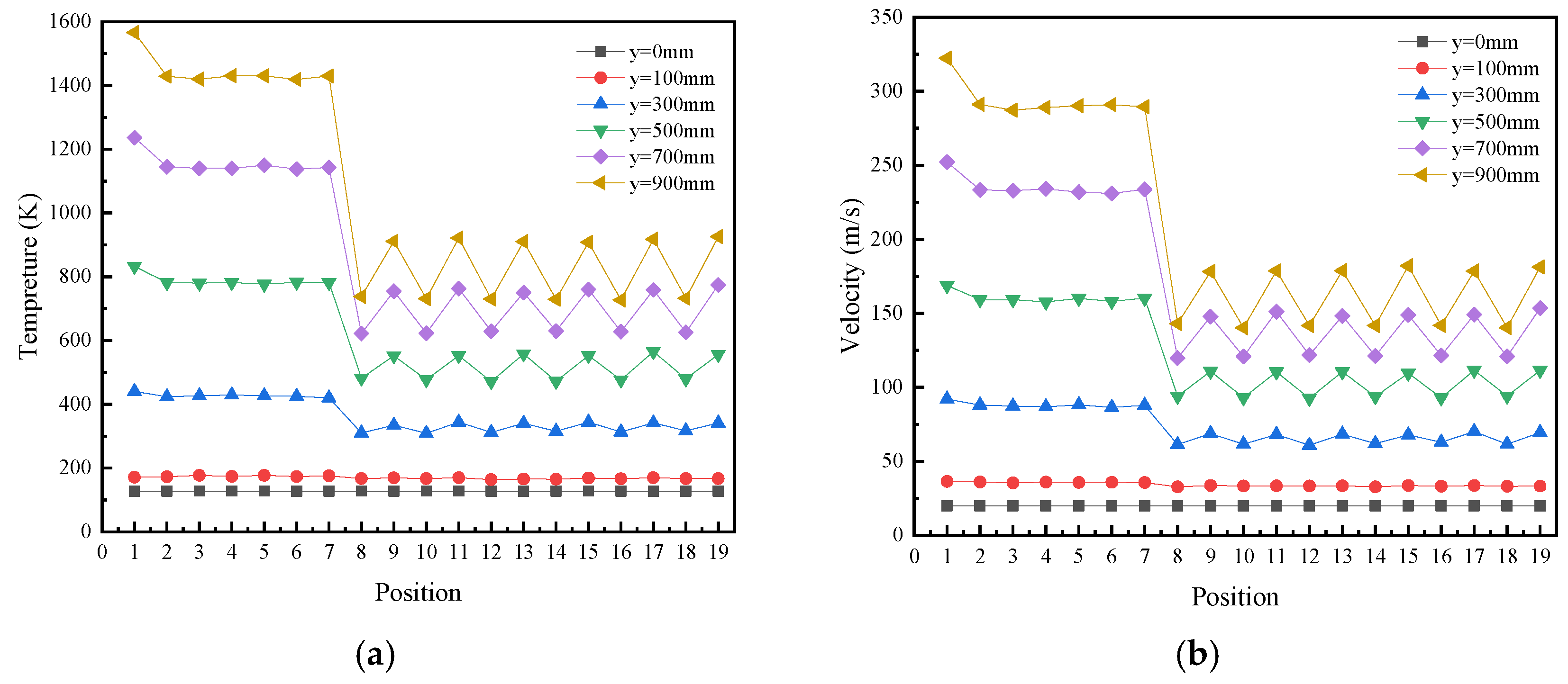
4.1. Temperature Distributions of the Radial Extraction Lines at Different Axial Positions

4.1.1. Conventional Fuel Elements

To investigate the internal characteristics of the fuel element, temperature data along radial extraction line1 and line2 (shown in Figure 9a) were extracted at various axial positions (y = 0, 100, 300, 500, 700, and 900 mm) and analyzed, as illustrated in Figure 9b,c. The positions of markers A′, B, B′, a′, b, b′, c, and c′ in the line charts correspond to those in Figure 9a. The analysis reveals that, despite a constant mass flow rate at the inlet, the fuel element’s overall temperature decreases radially from the center to the periphery due to thermal non-uniformity, while the temperature of the hydrogen coolant increases along the flow direction. A comparison of temperature distributions along line1 and line2 indicates non-uniform heat transfer from the fuel element to the hydrogen coolant, with the central region exhibiting higher coolant temperatures than the peripheral regions. The thermal boundary layer in the central region has a lesser influence on fluid temperature compared to the peripheral regions, and this influence diminishes further along the flow direction. Near the outlet, the temperature rise slows significantly, likely due to a sudden velocity drop, resulting in higher central velocities than wall velocities and the formation of recirculation zones over a short distance.
A comparative analysis of the temperature distributions along line1 and line2 under non-uniform inlet conditions in Figure 9c reveals that both the solid regions and hydrogen coolant channels exhibit smoother temperature profiles, with improved uniformity from the central to wall regions within the coolant channels and reduced temperature gradients. However, the overall temperature decreases by approximately 200 K compared to uniform inlet conditions. At the axial position y = 900 mm, the temperature differentials between coolant channels along line 1 decrease from 620 K to 192 K, while along line 2, the differentials reduce from 150 K to 92 K and from 665 K to 442 K, respectively, compared to uniform inlet conditions. These results demonstrate the significant impact of the inlet flow distribution on thermal homogenization and gradient mitigation within the fuel element, providing critical insights for optimizing coolant flow strategies in nuclear thermal propulsion systems.

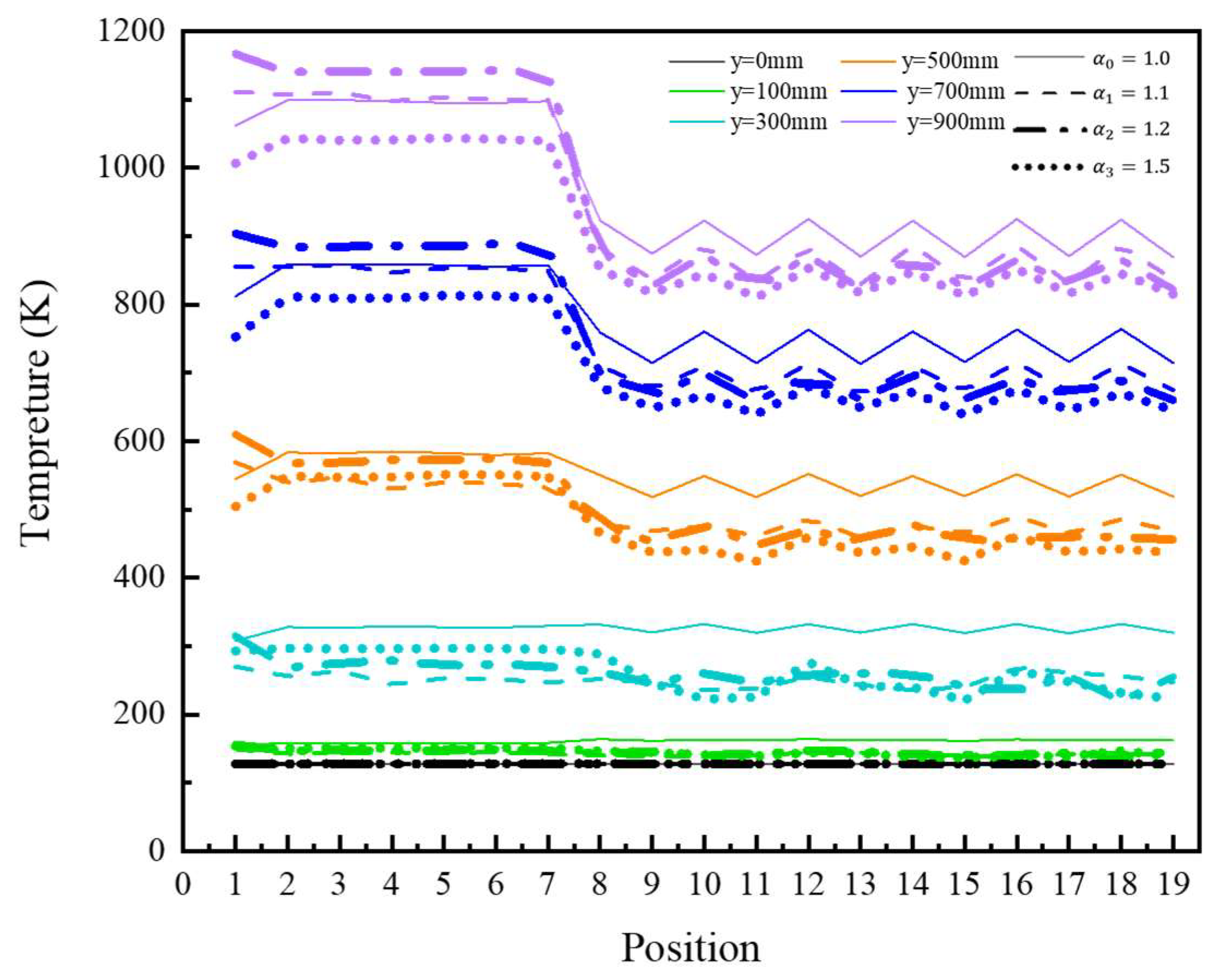
4.1.2. New Fuel Elements

The analysis of contour plots from the traditional fuel element reveals that heat is predominantly concentrated in the central region, with radial temperature data at various axial positions indicating lower temperatures in coolant channels closer to the periphery. Based on these observations, a new fuel element design was proposed. The inlet mass flow rate for the fuel element was set to 0.019 kg/s, and temperature distributions along radial extraction lines line 1 and line 2 under uniform inlet conditions were analyzed. The extraction lines are illustrated in Figure 10, with markers D′, E, E′, F, F′, d′, e, and e′ denoting the intersections between the extraction lines and coolant channels. These results provide a foundation for evaluating the thermal performance of the new design and its potential to mitigate radial temperature gradients in high-temperature propulsion systems.
The temperature distributions of line 1 and line 2 at different growth multiples are shown in Figure 11a for α 0 = 1.0 , Figure 11b for α 1 = 1.1 , Figure 11c for α 2 = 1.2 , and Figure 11d for α 3 = 1.5 . An analysis of the temperature distributions of Line 1 and Line 2 at different axial positions for the equal diameters in Figure 11a revealed that, along the direction of hydrogen mass flow, the temperature gradually increased. Compared with the temperature distributions of line 1 and line 2 in the conventional fuel element in Figure 9b, the outlet temperature of the hydrogen mass decreased by approximately 300 K. At different axial positions, the temperature increase trend was nearly the same along the radial direction from the center to the surrounding coolant channel; however, the temperature distribution among the radial coolant channels was more uniform.
Figure 11b–d show that the temperature in the solid region is almost unchanged compared with the equal-diameter fuel element in Figure 11a. However, there was a small change in the temperature in the coolant channel, namely, the temperature gradient increased and then decreased along the axial direction. When α 3 = 1.5 , the overall temperature decreased by approximately 200 K, the temperature distribution in the solid region increased slowly, and the temperature gradient gradually increased near the center region. The reason for this phenomenon may be that when α 3 = 1.5 , the diameter of the coolant channel at the center of the fuel element was smaller than that of other fuel elements, which led to an increase in the flow rate at this location and rapid heat loss.

4.2. Temperature Distribution at the Center of the Coolant Channel

Uneven temperatures can lead to irreversible damage to the fuel element structure, so the temperature distribution within the conventional fuel element needs to be clearly observed and optimized. To clearly observe the temperature changes in the coolant channel, the data at 19 coordinate points in the center of the coolant channel at different axial section locations were extracted. The locations of the coordinate points are shown in Figure 12.

4.2.1. Conventional Fuel Elements

Under uniform inlet conditions, the temperature variations within coolant channels across different axial cross-sections are shown in Figure 13a. The temperature distribution is relatively smooth in the central region of the fuel element (channels 1–7), while a sharp temperature drop occurs in the outer region (channels 8–19). Along the flow direction of hydrogen, the temperature fluctuations transition from mild to severe, with the lowest temperatures observed at the inner corners of the hexagonal prism (channels 8, 10, 12, 14, 16, and 18). This phenomenon is likely caused by a significant reduction in velocity at these locations, leading to flow instabilities.
An analysis of velocity data at the same locations (Figure 13b) reveals a consistent trend with temperature distributions. At the fuel element inlet, the temperature and velocity of the hydrogen coolant are uniform across all 19 channels, as defined by the boundary conditions. As the hydrogen flows axially, the combined effects of volumetric heat generation, thermal conduction from the fuel element’s outer walls, and radiation result in higher temperatures in the central channels and lower temperatures in the outer channels. The temperature difference between the central and outer channels increases progressively, and the temperature fluctuations among the outer channels intensify along the flow direction. These findings highlight the complex interplay between flow dynamics and thermal gradients in hexagonal prismatic fuel elements, providing critical insights for optimizing the coolant flow distribution and thermal management in nuclear thermal propulsion systems.
A comprehensive analysis of the temperature and velocity distributions at different locations of the fuel element under the uniform inlet conditions in Figure 13 revealed that an average flow rate at the middle location led to an even distribution of the temperature. The average flow rate in the outer region, which was due to the hexagonal prism structure, led to temperature fluctuations. To avoid temperature fluctuation, the inlet flow rate of the coolant channel in the fuel element was readjusted while ensuring the average distribution of the flow rate in the center region. The temperature of the fuel element center at region 1 was the highest. To reduce the temperature there, the flow rate of the corresponding position was increased to ensure that the temperatures of regions 2–7 were evenly distributed under the premise of uniformly increasing the flow rate of the corresponding region. To reduce the temperature fluctuations of regions 8–19, the flow rate of the corresponding position was adjusted. Compared with those at positions 9, 11, 13, 15, 17, and 19, the flow rates at the inner corners of the hexagonal column at positions 8, 10, 12, 14, 16, and 18 were lower.
Figure 14 shows the temperature distribution under the nonuniform inlet after adjusting the inlet flow rate of the fuel element. Compared with the uniform inlet condition, the overall temperature decreased by approximately 200 K. Before the axial direction of the fuel element, y = 500 mm, the temperature distributions at positions 1–19 were relatively uniform. After the axial direction, y = 500 mm, the temperature difference between the center region and edge region decreased from 300 K to 130 K. The temperature fluctuation decreased from 520 K to 300 K and from 690 K to 450 K. Considering the hydrogen flow velocity, the temperature decreased by 170 K, 220 K, and 240 K; 520 K to 300 K and 690 K to 450 K; and 170 K, 220 K, and 240 K. However, with the hydrogen flow velocity considered, the temperature fluctuations at the edge regions were weakened but still existed. These temperature fluctuations can be improved by using the impingement cooling scheme in [8].

4.2.2. New Fuel Elements

The center temperatures of the 19 coolant channels in the new fuel element were also extracted, and the temperature distribution is shown below in Figure 15. The different colors in the figure represent different axial distances, and different line shapes represent different growth multiples: black represents y = 0 mm, green represents y = 100 mm, cyan represents y = 300 mm, orange represents y = 500 mm, blue represents y = 700 mm, and violet represents y = 900 mm. Moreover, the solid line represents α 0 = 1.0 , the dashed line represents α 1 = 1.1 , the dash–dot line represents α 2 = 1.2 , and the dotted line represents α 3 = 1.5 .
An analysis of Figure 15 reveals that, compared to the traditional fuel element, the temperature distribution in the new fuel element remains relatively uniform up to the axial position y = 300 mm. At y = 300 mm, a slight temperature difference begins to emerge between the central and peripheral regions (notably between channels 7 and 8), with temperature fluctuations initiating in the peripheral monitoring points. Beyond y = 300 mm, the temperature difference between the central and peripheral regions gradually increases along the hydrogen flow direction, although the amplitude of temperature fluctuations in the peripheral regions remains nearly constant. Compared to the traditional fuel element, the axial distance at which the temperature difference between the central and peripheral regions emerges is shorter, and the magnitude of the difference is smaller. Additionally, the amplitude of temperature fluctuations in the peripheral regions is reduced. However, under the same volumetric heat source conditions, the overall temperature and hydrogen coolant outlet temperature are lower in the new design. These results demonstrate the new fuel element’s improved thermal uniformity and reduced gradient effects, offering significant potential for enhancing the performance and durability of nuclear thermal propulsion systems.
The temperature distribution within the fuel element was essentially the same under different growth multiples. From the overall view, the temperature fluctuation occurred at y = 300 mm when α 0 = 1.0 and clearly fluctuated at y = 500 mm; however, the temperature clearly fluctuated at y = 300 mm when α 1 = 1 . 1, α 2 = 1.2 , and α 3 = 1.5 . Regarding the direction of the hydrogen mass flow, the temperature difference between the center region and surrounding region exhibited a slight difference, but all of them were larger than that at α 0 = 1.0 . After axial y = 500 mm, compared with the other growth multiples, the temperature distribution inside the fuel element exhibited the same trend at α 3 = 1.5 , which was the same as that at other growth multiples. Additionally, after the axial direction y = 500 mm, compared with that of other growth multiples, the temperature fluctuation in the edge region was the smallest, at α 3 = 1.5 . Compared with the conventional fuel element, the temperature differences between the center and edge regions and the temperature fluctuations in the edge region always existed in the new fuel element; however, the temperature fluctuations gradually weakened with changes to the inlet conditions and to the structure.

5. Conclusions

In this paper, a circumferential variable diameter fuel element was proposed as the heat source and temperature distributor of a fuel element in the core of a reactor, and through a comparative analysis between a conventional fuel element and the new fuel element in the core of a nuclear thermal rocket engine, the following conclusions are drawn:
The overall temperature of traditional fuel elements under non-uniform inlet conditions and new fuel elements under uniform inlet conditions is lower compared to traditional fuel elements under uniform inlet conditions, but the temperature distribution is more uniform. Compared with the conventional fuel element under uniform inlet conditions, the overall temperature of the element under nonuniform inlet conditions decreased by approximately 200 K. However, the temperature distribution in the solid region was more uniform, the temperature difference between neighboring coolant channels decreased, and the temperature fluctuation in the peripheral region was weakened by approximately 25.6%. The overall temperature of the new fuel element with α 0 = 1.0 decreased by approximately 600 K, and the temperature gradient in the coolant channel gradually decreased. The temperature of the new fuel element with α 1 = 1.1 and α 2 = 1.2 did not change much compared with that of α 0 = 1.0 , and the overall temperature decreased by approximately 200 K with α 3 = 1.5 ; moreover, there was a clear increasing trend in the temperature distribution of the solid region along the radial direction. Compared to the new fuel element with α 0 = 1.0 , the temperature gradient in the coolant channels of the new fuel element with α 1 = 1.1 and α 2 = 1.2 tended to increase and then decrease along the axial direction. Finally, the degree of temperature fluctuation in the peripheral region of the new fuel element weakened by approximately 72.1% when compared with that of the conventional fuel element under uniform inlet conditions.
For both conventional and new fuel elements, the internal temperature boundary was in the range of the axial direction y = 300~500 mm. Before that, the temperature fluctuation of the fuel element was small, but after that, the fluctuations in the center temperature and the temperature of the surrounding area increased. Furthermore, temperature fluctuations began to appear in the peripheral area. Although the temperature difference and temperature fluctuation phenomena were mitigated by adjusting the inlet conditions and the position of the coolant channels, they still persisted. Moreover, the maximum temperature of the fuel elements in the nuclear thermal rocket engine is approximately 3000 K. Subsequent efforts will focus on optimizing the structure of the fuel elements to increase the outlet temperature of the coolant, thereby enhancing the overall performance of the nuclear thermal rocket engine.

Author Contributions

Conceptualization, M.S. and S.F.; software, M.S.; validation, M.S., K.G., and Y.T.; writing—original draft preparation, M.S.; writing—review and editing, S.F., K.G., Y.T., and W.L.; project administration, S.F.; funding acquisition, S.F. All authors have read and agreed to the published version of the manuscript.

Funding

This research was supported by the Provincial and Ministerial Youth Science Foundation (2023-JCJQ-ZQ-085).

Data Availability Statement

The data that support the findings of this study are available from the corresponding author upon reasonable request.

Acknowledgments

This study was supported by the Space Engineering University.

Conflicts of Interest

The authors declare no conflicts of interest.

Abbreviations

The following abbreviations are used in this manuscript:
LEULow-enriched Uranium.
FEFuel element.
ZrCZirconium carbide.
NERVANuclear engine for rocket engine application.
RNGRenormalization group theory.
NRXNational research experimental reactor.
SSTShear stress transport.

References

  1. Menglong, Z.; Yue, Z.; Baohe, W. Review and prospect of space nuclear propulsion system. J. Ordnance Equip. Eng. 2018, 39, 96–100. [Google Scholar]
  2. Vadim, Z.; Vladimir, P. Russian nuclear rocket engine design for mars exploration. Tsinghua Sci. Technol. 2007, 12, 256–260. [Google Scholar] [CrossRef]
  3. Clark, J.S.; Mcdaniel, P.; Howe, S.; Helms, I.; Stanley, M. Nuclear Thermal Propulsion Technology: Results of an Interagency Panel in FY 1991; Technical Report; NASA: Washington, DC, USA, 1993. [Google Scholar]
  4. Walton, L.; Sapyta, J. SNTP program reactor design. In Proceedings of the Joint Propulsion Conference and Exhibit, San Jose, CA, USA, 15–17 July 2013. [Google Scholar] [CrossRef]
  5. Powell, J.; Maise, G.; Paniagua, J. Mini-MITEE: Ultra Small, Ultra-Light NTP Engines for Robotic Science and Manned Exploration Missions. AIP Conf. Proc. 2006, 813, 879–888. [Google Scholar] [CrossRef]
  6. Furman, E.M.; Anghaie, S. Thermal hydraulic design analysis of ternary carbide fueled square-lattice honeycomb nuclear rocket engine. Am. Inst. Phys. 1999, 458, 1501–1506. [Google Scholar] [CrossRef]
  7. Donders, N.; Emrich, B.; Taylor, B.; Tucker, D.; Barnes, M.; Benensky, K. Study of a Tri carbide Grooved Ring Fuel Element for Nuclear Thermal Propulsion. In Proceedings of the 2018 ANS/ENS Nuclear and Emerging Technologies for Space Conference, Las Vegas, NV, USA, 26 February–1 March 2018. [Google Scholar]
  8. Yuliang, F.; Lin, L.; Hailiang, S.; Zhiqiang, W.; Guohua, Z.; Yu, W. Overview of fuel element development for nuclear thermal propulsion reactors. Aerosp. Gen. Technol. 2020, 4, 63–70. [Google Scholar]
  9. Belair, M.L.; Sarmiento, C.; Lavelle, T. Nuclear Thermal Rocket Simulation in NPSS. In Proceedings of the 49th AIAA/ASME/SAE/ASEE Joint Propulsion Conference, San Jose, CA, USA, 14–17 July 2013. [Google Scholar] [CrossRef]
  10. Joyner, C.R.; Jennings, T.; Hanks, D.E.; Levack, D.J. NTP Engine System Design and Modeling. In Proceedings of the AIAA 2022-4373, Las Vegas, NV, USA, 24–26 October 2022. [Google Scholar] [CrossRef]
  11. Duan, Z.; Zhang, J.; Han, Z.; Wang, M.; Wu, Y.; He, Y.; Tian, W.; Qiu, S.; Su, G. Nuclear thermal coupling optimization of baffled NTP reactor. Ann. Nucl. Energy 2023, 180, 109496. [Google Scholar] [CrossRef]
  12. Xianbao, Y.; Chao, L.; Wei, T.; Yonghong, Z.; Binhang, Z.; Zhangliang, M.; Jianjun, Z.; Haibo, T.; Furong, L. COMSOL-based study of flow channel blockage accidents in plate fuel assemblies. J. Three Gorges Univ. Nat. Sci. Ed. 2021, 43, 6. [Google Scholar] [CrossRef]
  13. Dong, H.; Fan, W.; Guo, Y. CFD investigation and optimization on flow distribution of plate-type assembly. Nucl. Tech. 2016, 39, 60–64. [Google Scholar] [CrossRef]
  14. Hess, H.L.; Kunz, H.R. A Study of Forced Convection Heat Transfer to Supercritical Hydrogen. J. Heat Transf. 1965, 87, 371. [Google Scholar] [CrossRef]
  15. Fang, Y.; Yu, Q.; Wang, C.; Tian, W.; Su, G.; Qiu, S. Heat transfer of hydrogen with variable properties in a heated tube. Int. J. Heat Mass Transf. 2023, 209, 124128. [Google Scholar] [CrossRef]
  16. Wang, J.C.; Kotlyar, D. High-resolution thermal analysis of nuclear thermal propulsion fuel element using Open FOAM. Nucl. Eng. Des. 2021, 372, 110957. [Google Scholar] [CrossRef]
  17. AI, Q.; Shuai, W.; Jia-Huan, W.; Haochun, Z.; Xinlin, X. Study on influencing factors of thermal characteristics of nuclear thermal propulsion cooling channel. J. Eng. Thermophys. 2018, 39, 2745–2748. [Google Scholar]
  18. Li, W.; Guan, C.; Song, H.; Chai, X.; Liu, X. Numerical investigation of heat transfer characteristics of moderator assembly employed in a low-enriched uranium nuclear thermal propulsion reactor. Front. Energy Res. 2022, 10, 875371. [Google Scholar] [CrossRef]
  19. Ji, Y.; Li, Z.G.; Sun, J.; You, E.; Minggang, L.; Shi, L. Numerical investigation and parametric study on thermal-hydraulic characteristics of particle bed reactors for nuclear thermal propulsion. Nucl. Technol. 2020, 206, 1155–1170. [Google Scholar] [CrossRef]
  20. Nam, S.H.; Venneri, P.; Kim, Y.H.; Sang, C.H.; Jeong, Y.H. Preliminary conceptual design of a new moderated reactor utilizing an LEU fuel for space nuclear thermal propulsion. Prog. Nucl. Energy 2016, 91, 183–207. [Google Scholar] [CrossRef]
  21. Zhang, J.; Wang, C.; Zhang, J.; Zhang, D.; Tian, W.; Qiu, S.; Su, G. Design research for the porous hexagonal prism shaped fuel element adopted in nuclear thermal propulsion reactor based on neutronics and thermal hydraulics coupled method. Ann. Nucl. Energy 2021, 150, 107847. [Google Scholar] [CrossRef]
  22. Altman, D. Thermodynamic Properties and Calculated Rocket Performance of Hydrogen at 20,000 K. Available online: https://www.osti.gov/biblio/4216735 (accessed on 18 March 2025).
  23. Krecicki, M.; Kotlyar, D. Low enriched nuclear thermal propulsion neutronic, thermal hydraulic, and system design space analysis. Nucl. Eng. Des. 2020, 363, 110605. [Google Scholar] [CrossRef]
  24. Ju, W.; Dong, X.; Lu, R.; Shen, H.; Zhao, F.; Tan, S. Heat transfer performance of high temperature and high velocity hydrogen flow and analysis of blockage characteristics. Int. J. Adv. Nucl. React. Des. Technol. 2022, 4, 205–216. [Google Scholar]
Figure 1. Schematic diagram of the radial and axial cross-sections of the fuel element. (a) Schematic diagram of the radial cross-section; (b) schematic diagram of the axial cross-section.
Aerospace 12 00290 g001
Figure 2. Axial distribution of the volumetric heat in the fuel element.
Aerospace 12 00290 g002
Figure 3. Schematic diagram of the mesh division.
Aerospace 12 00290 g003
Figure 4. Centerline temperature distributions of the fuel element with different grid sizes.
Aerospace 12 00290 g004
Figure 5. Axial temperature distributions at Station 1 under different models.
Aerospace 12 00290 g005
Figure 6. Schematic diagram of conventional fuel elements under different work conditions. (a) Uniform inlet conditions; (b) nonuniform inlet conditions.
Aerospace 12 00290 g006
Figure 7. Schematic diagram of the new fuel element.
Aerospace 12 00290 g007
Figure 8. Temperature and velocity distributions of the fuel element cross-section at different axial positions.
Aerospace 12 00290 g008
Figure 9. Temperature distributions of different radial extraction lines along the axial direction in conventional fuel elements. (a) Schematic diagram of the radial Line 1 and Line 2 positions in conventional fuel elements; (b) uniform entrance conditions; (c) nonuniform entrance conditions.
Aerospace 12 00290 g009
Figure 10. Schematic diagram of the radial line 1 and line 2 positions in Type II fuel elements.
Aerospace 12 00290 g010
Figure 11. Temperature distributions of different radial extraction lines along the axial direction in the new fuel element. (a) α 0 = 1.0 ; (b) α 1 = 1.1 ; (c) α 2 = 1.2 ; (d) α 3 = 1.5 .
Aerospace 12 00290 g011
Figure 12. Schematic distribution of the 19 coordinate points. (a) Conventional fuel element; (b) new fuel element.
Aerospace 12 00290 g012
Figure 13. Temperature and velocity distributions at the center of the coolant channel under uniform inlet conditions for the conventional fuel element. (a) Temperature distribution; (b) velocity distribution.
Aerospace 12 00290 g013
Figure 14. Temperature distribution at the center of the coolant channel under nonuniform inlet conditions for the conventional fuel element.
Aerospace 12 00290 g014
Figure 15. Temperature and velocity distributions at the center position of the coolant channel under uniform inlet conditions for the new fuel element.
Aerospace 12 00290 g015
Table 1. Geometric parameters of the fuel element.
NameStructural ParametersValue (mm)
Fuel elementFace-to-face distance19.05
Coolant channel diameter2.34
Coolant channel spacing4.4
Element length1000
Table 2. Fuel element cell information by size.
CaseNumber of Boundary Layers in Fluid RegionSurface Mesh Size of the Fluid Region\mmMesh Size\mmSkewness Total   Number   of   Cells \ × 10 7
130.51.00.3011.781
230.61.50.1530.921
331.05.00.2540.267
450.22.00.2394.350
Table 3. New fuel element design parameters.
Factor   of   Growth   α i d1/mmd2/mmd3/mm
1.02.342.342.34R1 = d1; R2 = 3.5 mm; R3 = 7.0 mm
1.12.002.202.42R1 = d1; R2 = 3.5 mm; R3 = 7.0 mm
1.21.742.082.50R1 = d1; R2 = 3.5 mm; R3 = 7.0 mm
1.51.181.772.65R1 = d1; R2 = 3.0 mm; R3 = 6.5 mm
Table 4. Summary of the entrance conditions.
Fuel ElementsUniform Entrance ConditionsNonuniform Entrance Conditions
Conventional fuel elements
New fuel element α 0 = 1.0 ×
α 1 = 1.1 ×
α 2 = 1.2 ×
α 3 = 1.5 ×
In the table, “√” means that the working condition was calculated, and “×” means that the working condition was not calculated.
Disclaimer/Publisher’s Note: The statements, opinions and data contained in all publications are solely those of the individual author(s) and contributor(s) and not of MDPI and/or the editor(s). MDPI and/or the editor(s) disclaim responsibility for any injury to people or property resulting from any ideas, methods, instructions or products referred to in the content.

