1. Introduction
In the modern era of space exploration, numerous spacecraft are launched with a limited communication system. These spacecraft may possess only an omnidirectional antenna and lack an onboard Tracking and Data Relay Satellite (TDRS) transponder capable of coherently transmitting a carrier signal through TDRS. Due to these limitations, alternative methods of tracking must be explored and utilized to accurately locate and communicate with the spacecraft.
One such alternative method is Differenced One-Way Doppler (DOWD) tracking, which has proven to be a valuable tool in overcoming the challenges presented by unstable onboard oscillators when using strictly One-Way Doppler (OWD) data. DOWD tracking measurement requires simultaneous OWD tracking from two non-collocated TDRSs. The process of differencing two OWD measurements results in a DOWD measurement, which offers precise information about the spacecraft’s position and velocity, and it can be used to estimate a spacecraft’s trajectory when other data types are not available. The effectiveness of DOWD measurements is largely dependent on the availability and performance of satellite communication networks such as the National Aeronautics and Space Administration (NASA) Space Relay (SR) [
1]. The SR is a network of communication satellites that provides a continuous link between ground stations and user satellites, enabling real-time data transfer and control.
A DOWD-based user spacecraft trajectory, however, is also dependent on the accuracy of the TDRS orbits used to transmit and receive radio signals. TDRS is a critical component of the DOWD technique as it provides a stable and reliable link for transmitting and receiving the radio signals necessary for the measurement. Any errors in the orbit of the TDRS satellites could result in changes to the radio signal path and cause inaccuracies in the DOWD measurements, which in turn affect the accuracy of the user satellite orbits.
Errors in the orbit of the TDRS satellites can occur due to a variety of factors, including perturbations from other celestial bodies, gravitational potential anomalies, inaccurate modeling of the non-gravitational forces, inaccuracies in the satellite’s onboard instruments, and measurement errors. These errors can accumulate over time and lead to significant deviations from the satellite’s predicted orbit.
To correct these errors, the Bilateration Ranging Transponder System (BRTS) and Telemetry, Tracking, and Command (TT&C) measurements [
1,
2] are used to precisely track TDRS position and velocity as it orbits the Earth. By analyzing these sets of measurements, the TDRS orbit can be determined within 40 m of accuracy [
3]. In contrast, reduced tracking, for instance, range-only (TT&C) could severely impact the accuracy of the TDRS satellites.
This paper analyzes OWD tracking data from several spacecraft received by the Flight Dynamics Facility (FDF) at NASA Goddard Space Flight Center (GSFC). An analysis of TDRS orbit error impact on DOWD-based satellite orbits was conducted when the TDRS satellite orbits were determined using TT&C-only measurements. The study additionally investigated the impact of a TT&C-only TDRS orbit on the precision of the Local Oscillator Frequency offset determination by analyzing the one-way Doppler tracking data from the user spacecraft.
2. Background
The use of DOWD as a tracking technique for orbit determination was first investigated in 1977 by conducting covariance analyses to verify its effectiveness [
4]. At that time, DOWD was employed to track spacecraft that lacked transponders compatible with the TDRS satellites. This was part of an initiative to track user spacecraft that were without such transponders, and DOWD’s efficacy was validated by comparing its results with the FDF’s operational Orbit Determination (OD) solutions for the Upper Atmosphere Research Satellite (UARS), a NASA spacecraft that researched the Earth’s upper atmosphere [
5]. Since then, DOWD has found various applications and is frequently used as an early orbit determination technique when a spacecraft’s onboard navigation systems are not fully functional during launch. Additionally, it is used for spacecraft lacking coherent tracking or onboard navigation methods, as well as for spacecraft with non-TDRS compatible transponders or transceivers that are not spread spectrum [
6].
However, an accurate knowledge of the orbits of the TDRS satellites is essential for conducting DOWD measurements. The FDF plays a crucial role in determining and maintaining the orbits of the TDRS constellation. The FDF is prime for analyzing the ground-based tracking data to precisely determine the definitive and predicted position and velocity of each TDRS satellite. The FDF currently relies on two types of data, BRTS and TT&C, to determine the ephemerides of the TDRS satellites. The BRTS measurements often involve tracking through multiple stations and encompass both range and Doppler measurements. In contrast, TT&C solely employs single station range measurements.
In light of the potential financial implications linked to the replacement of aging BRTS transponders, the FDF undertook a series of analyses on the first generation of TDRS satellites more than two decades ago. The objective of these analyses was to explore alternative methodologies for TDRS orbit determination that do not rely on BRTS tracking measurements [
7]. One of these alternatives involved using only TT&C measurements. The use of TT&C measurements offers a notable advantage over BRTS measurements due to its higher transmitting frequency, which results in significantly less atmospheric refraction of signals (around 50 times less). However, it should be noted that TT&C measurements rely on single-site geometry, which results in a high correlation to the TDRS states. This strong correlation increases the risk of introducing orbit errors if biases associated with TT&C measurements are not adequately accounted for. The objective of this study is to evaluate the reliability of the usage of TT&C-only measurements for determining the orbits of second and third-generation TDRS satellites, as well as its potential effects on the orbits of user spacecraft relying on DOWD measurements.
3. Tracking Measurement Overview
3.1. DOWD Measurements
DOWD employs an open-loop methodology for tracking data to mitigate any impact from the user spacecraft transmitted frequency offset. This technique involves OWD measurements, where a radio signal is transmitted from the spacecraft, received by two TDRSs, frequency translated, and then independently relayed to the ground stations.
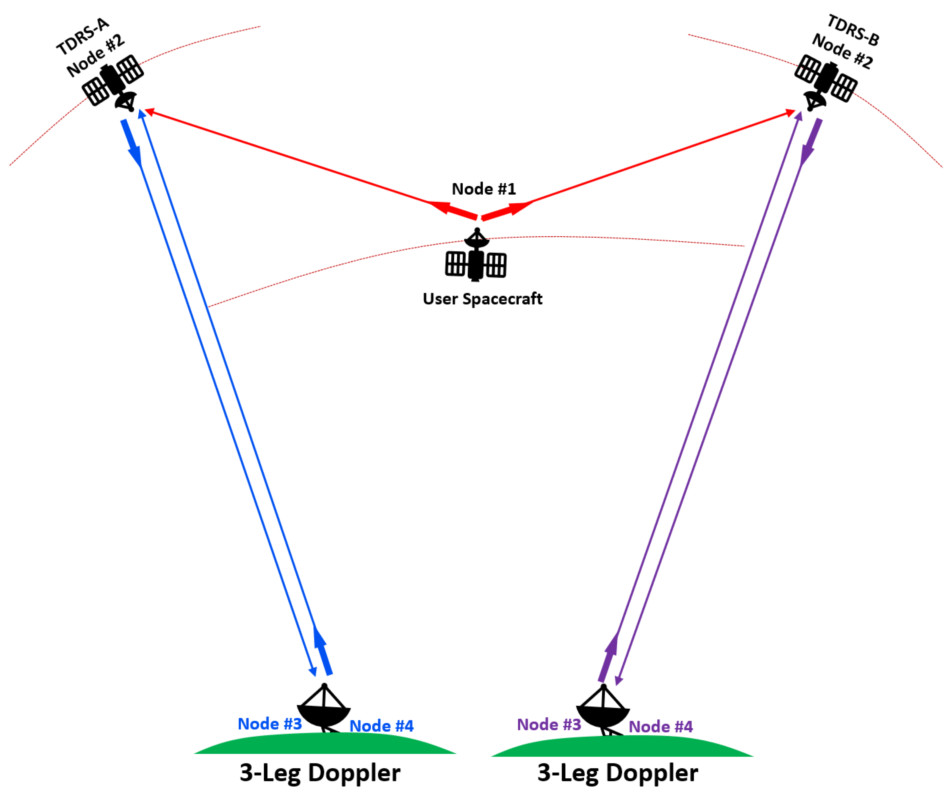
Figure 1 illustrates the OWD tracking configuration utilized by user spacecraft in conjunction with two TDRS satellites. The signal transmission process involves two distinct paths, starting with the user spacecraft at Node #1. The first path entails transmitting a signal from the user spacecraft to two TDRS satellites located at Node #2. The second path involves transmitting a signal from a ground station positioned at Node #3 to the TDRS satellite at Node #2. The received signal at the TDRS satellite is then combined with the signal from the first path before being transmitted back to the ground station at Node #4. This configuration is also known as three-legged Doppler measurements.
In general, the accuracy of OWD measurements is influenced by a variety of factors. These include atmospheric refraction, the offset of the user spacecraft antenna, the reference clocks, delays in the transponder, and the bias in the oscillator frequency. Consequently, these measurements are not ideal for determining orbits with high precision. The FDF has developed a technique that involves subtracting two distinct OWD measurements obtained from the pair of TDRS satellites that share the same time tag. This process results in a Differenced One-Way Doppler, DOWD, measurement [
8].
Assuming a spherically symmetric atmosphere, the signals received from different TDRSs are subject to essentially the same atmospheric corrections, and taking the difference between pairs of OWD measurements can effectively cancel out these corrections. As a result, the resulting DOWD tracking measurements can be as accurate as two-way Doppler measurements [
5,
9]. However, errors arising from the differences in propagation delays between the user spacecraft and the two receiving TDRSs, as well as those resulting from the drift rate of the user spacecraft’s transmission frequency, persist in the signal [
8].
DOWD Benefits and Limitations
The DOWD measurement is critical during the launch and early orbit phases of a spacecraft, particularly when onboard navigation systems are not yet fully operational, and the spacecraft lacks coherent signal capabilities. By addressing these challenges, DOWD eliminates the need for an ultra-stable oscillator (USO) during these initial stages. For example, while many spacecraft are equipped with GPS receivers, these systems are often activated only after the spacecraft reaches orbit. The DOWD technique not only provides an interim OD solution during this period but also aids in verifying the accuracy of GPS receivers. Additionally, integrating DOWD measurements with other tracking data, such as radar range and angle data, improves OD precision while simultaneously reducing the number of radar passes required, which could lead to cost savings for the mission.
Despite its advantages, the DOWD technique has notable limitations. At least four DOWD passes are generally needed to obtain a reliable OD solution. Furthermore, the technique requires two TDRS spacecraft to simultaneously receive an S-band signal from the user spacecraft for DOWD measurements to be performed. Since these measurements rely on the precise positioning of TDRSs in space, the accuracy of DOWD processing is heavily dependent on the precision of TDRS orbital data. As a result, higher uncertainties in TDRS orbits can restrict the overall accuracy of the user spacecraft’s orbit determination.
3.2. TDRS Measurements
The TDRS system consists of a constellation of geosynchronous satellites orbiting around the Earth [
1], each equipped with multiple antennas for communication and tracking. The TDRS satellites are strategically positioned to provide complete coverage of spacecraft in Low Earth Orbit (LEO). These satellites are operated by NASA and designed to provide continuous communications coverage between Earth and orbiting spacecraft, including the International Space Station, the Hubble Space Telescope, and various other satellites. At present, the TDRS orbit is obtained by the FDF through the utilization of range and Doppler tracking measurements obtained from TT&C and BRTS systems.
3.2.1. TT&C Measurements
Carrier tracking is a critical process in satellite operations that involves locating and establishing a connection with a satellite from a ground station. This process is achieved using the principle of phase coherence, which involves creating a two-way-coherent signal.
In practice, carrier tracking is typically accomplished by synchronizing the downlink communication frequency with a predetermined ratio of the uplink frequency. This ratio ensures that the phases of the uplink and downlink signals are in synchronization, which is crucial for reliable communication.
To establish a connection with the TDRS, the satellite first searches for and validates the uplink frequency based on the predetermined parameters. Once the uplink frequency is validated, the TT&C subsystem implements commands to set the frequency of the downlink communications, which is related to the uplink frequency through a prespecified ratio. This synchronization of the uplink and downlink frequencies not only enables the ground station to lock onto the satellite quickly but also ensures that the expected downlink frequency is known in advance.
The TT&C tracking configuration is depicted in
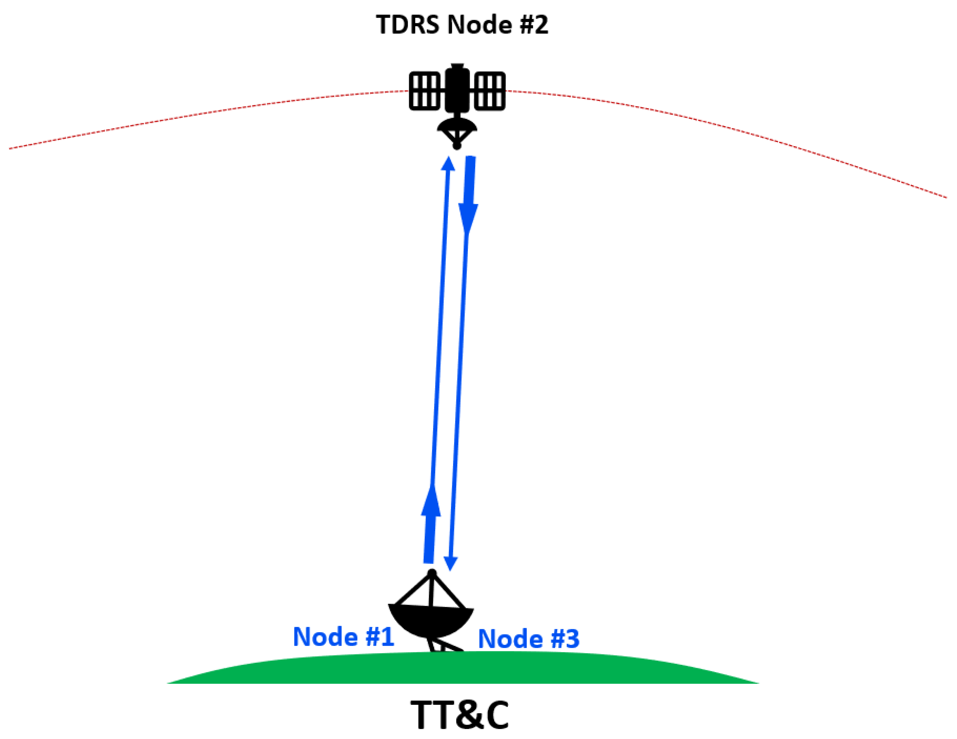
Figure 2. In this setup, a tone is modulated onto the uplink frequency, which is then transmitted from the ground station (Node #1) to the TDRS (Node #2). Upon receiving the signal, the TT&C subsystem of the TDRS adds the same tone to the downlink signal and sends it back to the ground station (Node #3). This enables the ground station to determine the round-trip time for the tone to travel from the station to the satellite and back. In general, the ground station located at Node #1 is the same as the one situated at Node #3.
Using the round-trip time, the command segment can determine the distance between the ground station and the satellite, thereby establishing the range. As such, the actual location of the satellite can be determined. TDRS TT&C tracking events generally occur every hour, with accuracy ranging between 1 and 3 m (a typical residual range of FDF’s operational solutions).
3.2.2. BRTS Measurements
The BRTS system is designed to provide highly accurate range and Doppler measurements necessary for determining the TDRS spacecraft’s orbit. The BRTS consists of ground-based transponders that are treated as if they were TDRS user spacecraft. Since their positions are precisely known, by tracking the BRTS transponders the trajectory of the TDRS can be determined with great accuracy.
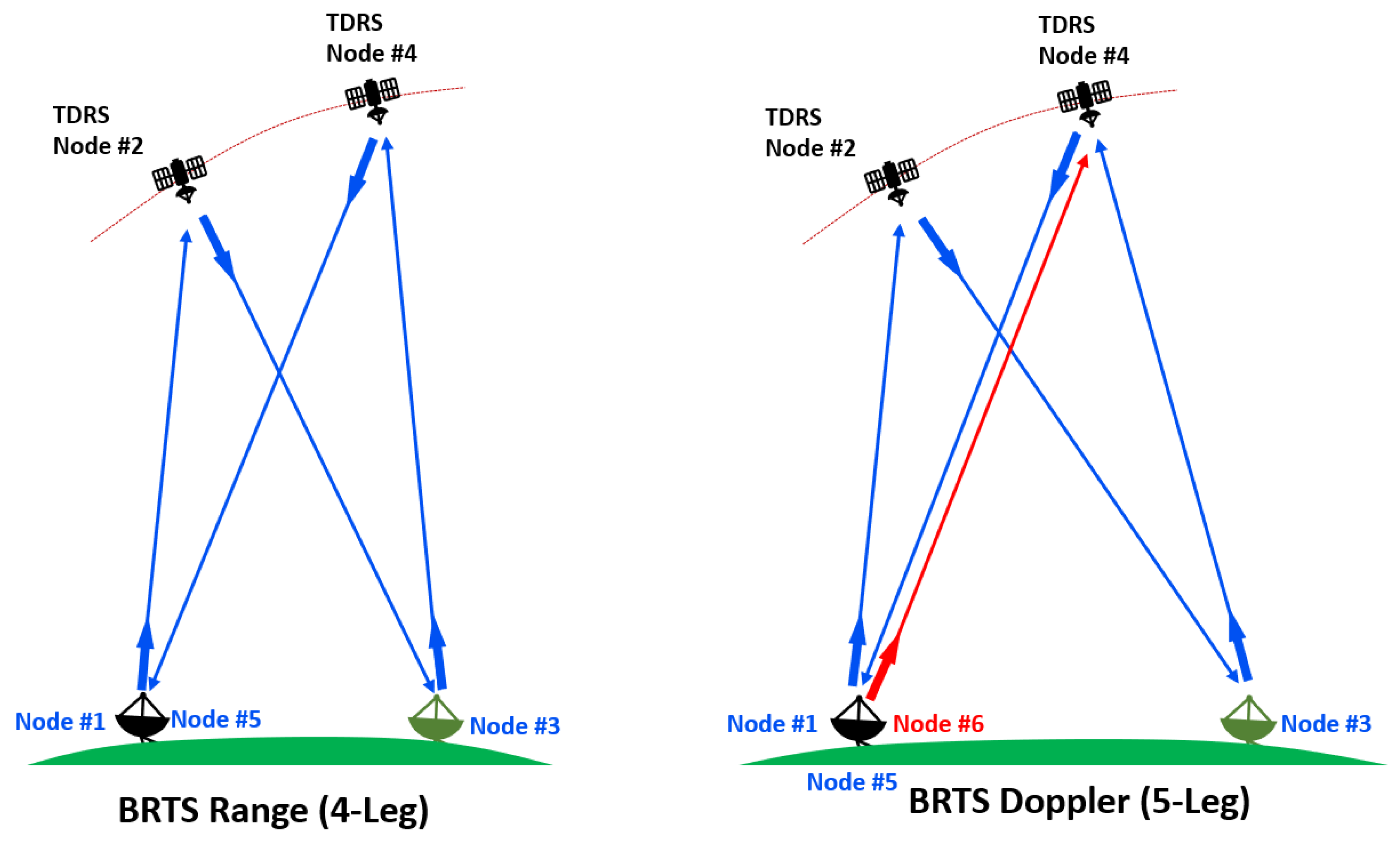
Figure 3 illustrates the tracking configuration of the BRTS measurements. The BRTS employs radio signals to measure the distance between two points, and in this setup, the signals in the same round-trip link are generated by the same atomic ground clock. This coherence in signal generation eliminates the effects of clock phenomenology and relativity, ensuring that the measurements obtained are accurate and reliable. As such, the four-legged range and five-legged Doppler measurements are two-way coherent measurements.
The measurement of the range utilizing four-legged methodology entails measuring the duration of propagation for a radio signal traveling from a transmitter (Node #1) to a receiver (Node #5); see
Figure 3. Specifically, the process involves the emission of a signal from the ground station (Node #1) to the TDRS satellite (Node #2), which is subsequently retransmitted by the satellite’s transponder to the BRTS transponder (Node #3). After receiving the signal, the BRTS transponder sends it back to the TDRS (Node #4), which ultimately forwards it to the ground station (Node #5).
The Doppler measurement, on the other hand, employs a five-legged methodology to account for the frequency drift of a signal as a consequence of the relative motion between the transmitters and receivers. The BRTS Doppler measurement method is established by creating two signal pathways. The first signal path starts from the ground station (Node #1) and is transmitted to the TDRS satellite (Node #2). It is then received by the satellite and retransmitted by its transponder to the BRTS transponder (Node #3). The BRTS transponder subsequently retransmits the signal to the TDRS satellite (Node #4). At Node #4, the signal is combined with the second signal path employing a signal mixer. The mixed signal is transmitted to the receiving ground station at Node #5. The second signal is initiated from the same ground station at Node #1 but at a different transmission time (Node #6). This signal is transmitted to the TDRS satellite at Node #4, mixed with the first path’s signal at Node #4, and then sent back to the ground station at Node #5.
In comparison to TT&C measurements, BRTS measurements are considerably more complicated. Typically, multiple ground transponders are used to obtain these measurements, with each transponder positioned at a different relative geometry. Such multi-geometry configuration offers potential benefits in terms of more accurate orbit determination compared to single-site TT&C measurements. The BRTS tracking events generally occur every four hours and measures range with an accuracy of 5 to 10 m, while Doppler measurements are precise up to 0.02 Hz (a typical residual range of FDF’s operational solutions).
4. Methodology
The section provides a detailed overview of the methodologies that were utilized in this study. In
Section 4.1, a flow chart of the initial setup is presented, which highlights the key steps involved in the process of configuring and setting up the analysis. This flow chart serves as a critical reference point for understanding the overall framework of the study and the sequence of events that were carried out.
Section 4.2 outlines the orbit determination tool and the typical procedures involved in the process.
Section 4.3 and
Section 4.5 describe the user spacecraft and TDRS orbit determination procedures and models. These sections provide details of the dynamical modeling, measurement modeling, and tools that were employed to determine the orbits of the spacecraft and TDRS accurately. This information is critical for understanding the operational context of the study and the underlying mechanisms that govern the accuracy of the user spacecraft and TDRS satellites’ orbits.
Finally,
Section 4.7 outlines the process of calculating the Local Oscillator Frequency offset using one-way Doppler residuals.
4.1. Analysis Setup
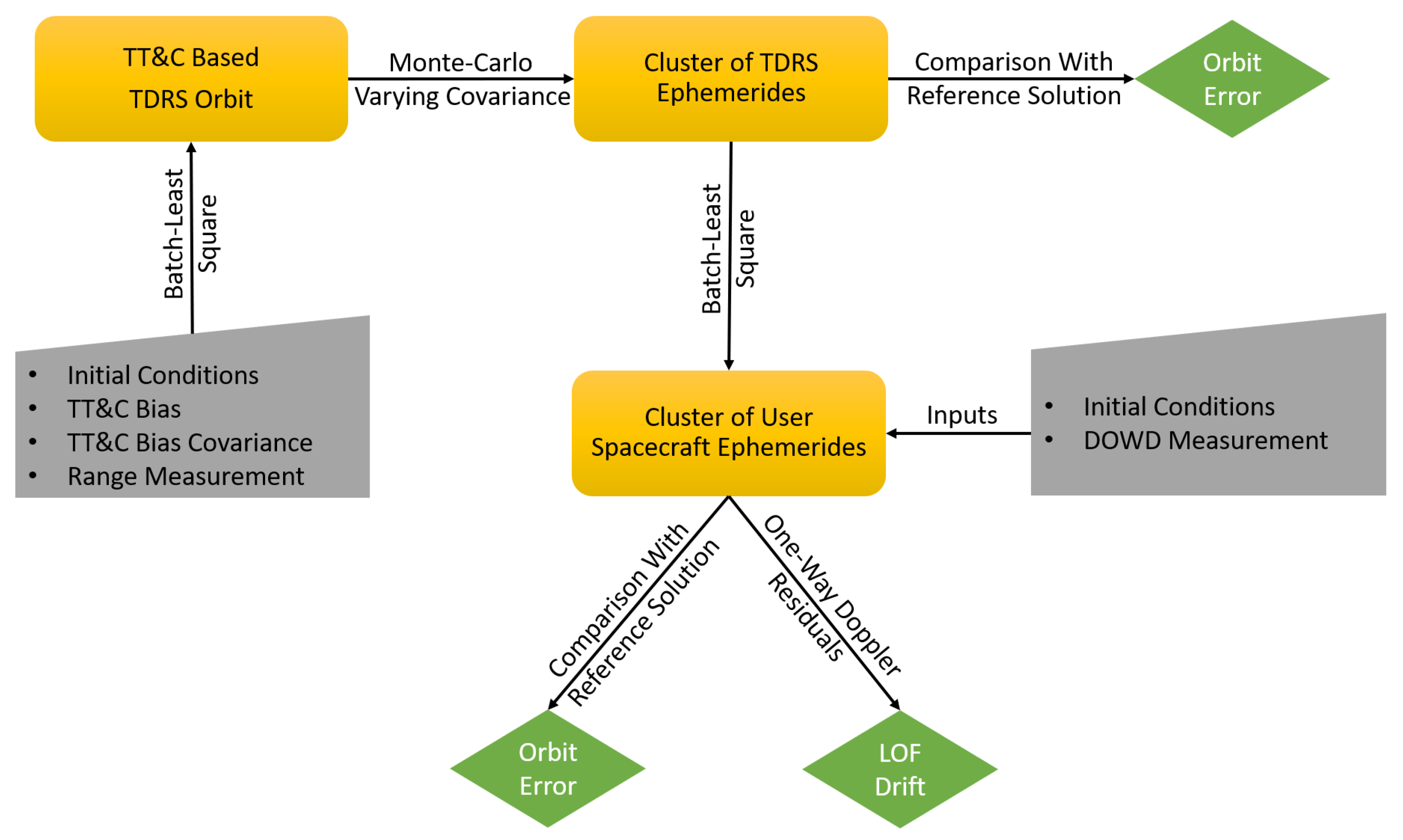
Figure 4 depicts the schematic of the analysis setup used in this study. The initial step involves the selection of user spacecraft that have been supported by the FDF for DOWD analysis, as described in
Section 4.3. Once the user spacecraft is identified, the list of the TDRS satellites used for acquiring DOWD measurements is determined. In the subsequent step, the TDRS orbit is reconstructed using TT&C measurements and weighted Batch Least Squares (BLS) techniques.
As the TT&C-only solution is sensitive to the a priori knowledge of TT&C bias and its covariance, a Monte-Carlo analysis is conducted to account for the uncertainties in the bias and its covariance. In this analysis, over 40 TDRS orbit solutions are created, each varying the covariance of the TT&C bias. The purpose of generating this cluster of TDRS orbits is to understand how TDRS orbit errors are influenced by the choice of a priori covariance for the TT&C bias. The next step involves a comparative analysis of the obtained orbit with respect to the reference solution (based on TT&C and BRTS measurements). This setup enables the evaluation of the accuracy of TDRS orbit determination using only TT&C measurements and the identification of factors affecting the orbit accuracy.
To determine the user spacecraft orbit, the TDRS ephemerides cluster is used in combination with DOWD measurements and weighted BLS techniques. Following the orbit reconstruction, an orbit comparison is carried out with respect to the FDF operational solution to identify discrepancies and gain insights into the sources of error. This analysis assesses the accuracy and reliability of the TDRS orbits and their impact on user spacecraft orbit determination (
Section 5).
4.2. Orbit Determination Tool
The Goddard Trajectory Determination System (GTDS) is utilized for both user and TDRS satellites to perform state vector propagation, orbit determination, ephemeris generation, and tracking data evaluation [
10]. GTDS uses a batch estimation technique based on a weighted least squares approach, which consists of five main steps.
In the first step, the state vectors and state-transition matrix are propagated using a Cowell-type numerical integration method. This technique allows for the determination of the satellite’s position and velocity as a function of time based on the forces acting on the spacecraft, such as gravity, solar radiation pressure, and atmospheric drag.
In the second step, the observations and their partial derivatives are computed using integrated trajectory and measurement models. GTDS can process numerous types of measurements simultaneously, which can be broadly classified into three main categories: Range, Doppler, and Angles. The trajectory models account for the spacecraft’s motion, and the measurement models represent the signals transmitted and received by the satellite, which are affected by various factors such as atmospheric conditions and equipment performance.
The third step involves computing a series of observation residuals by taking the difference between real observations and computed observations over a selected period, known as the data arc. This comparison provides a measure of the accuracy of the computed trajectory and helps to identify any discrepancies.
The fourth step is to form the error function by summing the weighted squares of these observation residuals. The weighting factors are determined based on the expected accuracy of the observations and the modeling errors. The error function provides a measure of the error between the real observations and the computed observations.
In the final step, the error function is minimized with respect to the selected subset of the estimation parameters. This process is repeated several times until convergence is achieved. Each iteration starts with a new trial trajectory generated using the estimation parameters obtained from the previous iteration. This approach allows for the refinement of the estimation parameters and the improvement of the accuracy of the computed trajectory.
For several decades, GTDS has been an invaluable asset to the FDF. This tool has been an essential component of the FDF’s operational procedures for navigating numerous satellites and computing DOWD-based user ephemerides.
4.3. User Spacecraft
For a period spanning more than two decades, the FDF has used DOWD measurements for missions equipped with oscillators that are incapable of being made coherent with the carrier uplink. In this study, DOWD analysis has been conducted on four user satellites that the FDF has supported in recent times. All four satellites are in the LEO regime and possess vastly differing orbital configurations, as shown in
Figure 5. This diversity of orbital geometries aids in identifying any discrepancies that could occur due to the varying geometry.
4.3.1. IXPE
The Imaging X-ray Polarimetry Explorer (IXPE) is a NASA space mission to advance our understanding of the astrophysical phenomena occurring in the universe. It has been specifically designed to measure the polarization of X-rays that emanate from various astrophysical sources, enabling scientists to gain a deeper insight into the structure and properties of these sources [
11].
On 9 December 2021, the IXPE spacecraft was successfully launched into space from the Kennedy Space Center in Florida, USA. The spacecraft was placed into a low-Earth orbit, with an altitude of about 540 km, an eccentricity of 0.00167, and an inclination of 0.2 degrees (equatorial orbit), enabling it to observe a wide range of astrophysical sources with great precision.
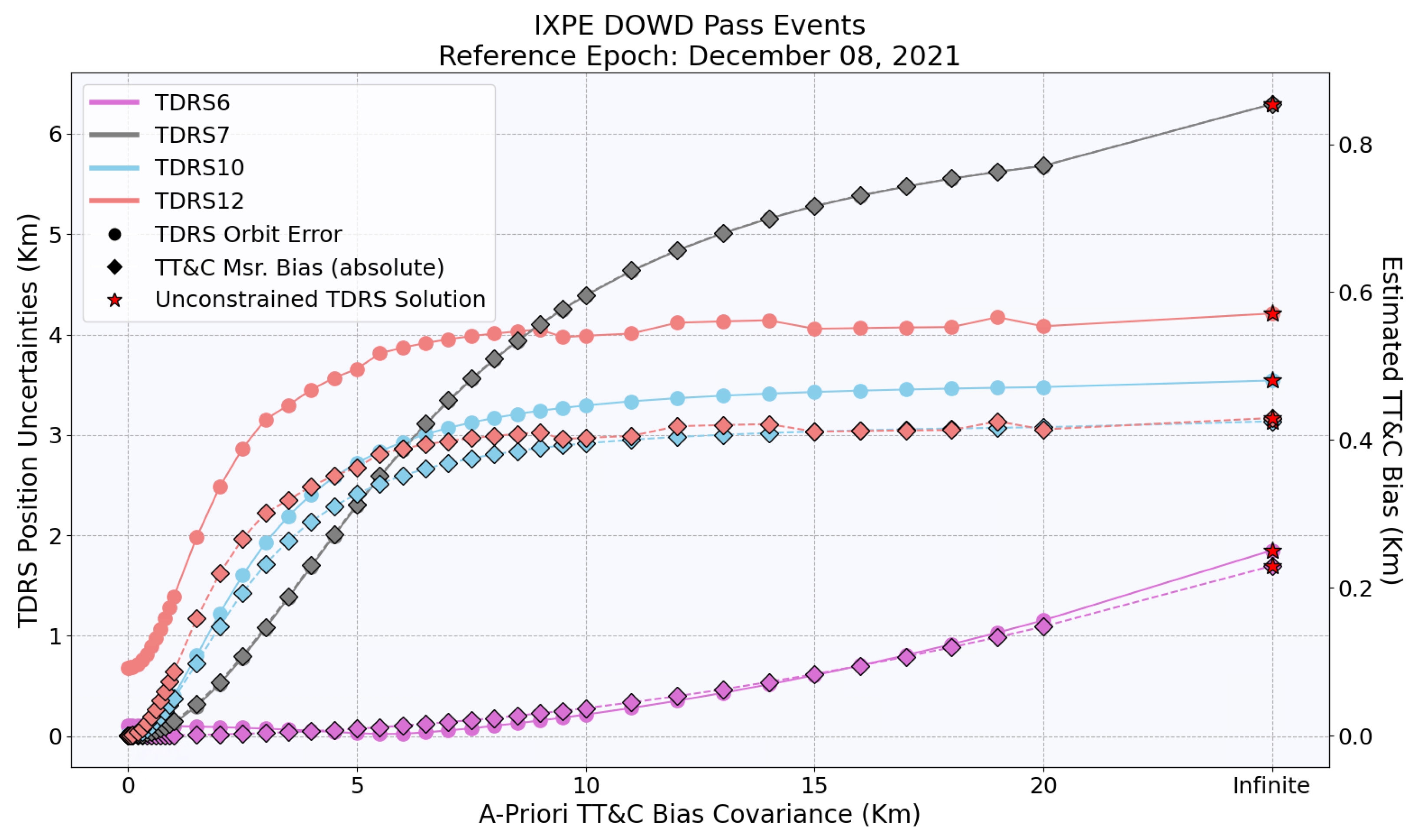
The FDF played a critical role in the early orbit support of the IXPE mission. The FDF received six passes of DOWD measurements acquired from constellations of the TDRS satellites, namely TDRS-6, -7, -10, and -12, on 8 and 9 December 2021. In this study, these passes were reprocessed to reconstruct IXPE orbit using an arc length equivalent to 7 IXPE revolutions.
4.3.2. LANDSAT-9
LANDSAT-9 is a satellite mission of the United States Geological Survey (USGS) in partnership with NASA. The LANDSAT-9 spacecraft was launched into space on 27 September 2021 from the Kennedy Space Center in Florida, USA. The spacecraft was placed in a polar low-Earth orbit with an altitude of about 705 km, an eccentricity of 0.00145, and an inclination of 98.2 degrees.
The mission is designed to continue the LANDSAT program’s legacy of providing critical information about the Earth’s natural resources and environment. The mission’s primary goal is to collect high-quality, multispectral images of the Earth’s surface that can be used for a wide range of scientific and commercial applications [
12].
The FDF semi-annually performs proficiency DOWD OD analysis for the LANDSAT-9 spacecraft. Using an arc length equivalent to 17 LANDSAT-9 revolutions, the LANDSAT-9 orbit was reconstructed through 4 DOWD measurement passes received on 3 April 2022. TDRS-7, -10, -11, and -12 satellites were used during these passes.
4.3.3. LANDSAT-8
The LANDSAT-8 mission is one of the satellites in the LANDSAT series that precedes LANDSAT-9. As with LANDSAT-9, it was developed and operated in collaboration with NASA and USGS, with comparable objectives and instrumentation on board [
13].
On 11 February 2013, the LANDSAT-8 spacecraft was launched from the Kennedy Space Center in Florida, USA. It was positioned in a polar low-Earth orbit at an altitude of approximately 705 km, inclined at 98.2 degrees with an eccentricity of 0.0007.
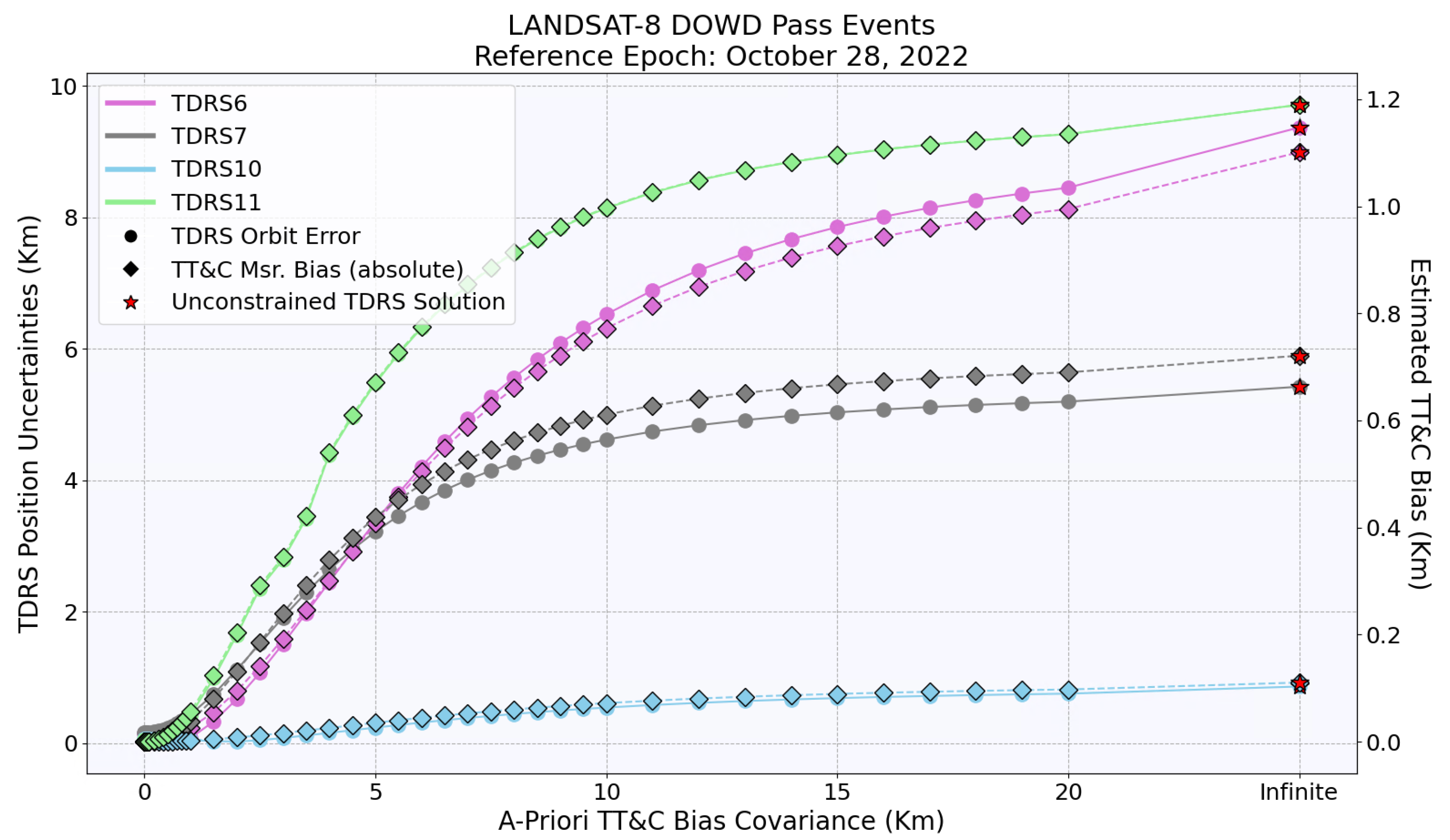
Analogous to the support provided for LANDSAT-9, a semi-annual proficiency DOWD OD analysis was also carried out by the FDF for LANDSAT-8. Using an arc length equivalent to 11 LANDSAT-8 revolutions, the LANDSAT-8 orbit was reconstructed through three DOWD measurement passes received on 27 and 28 October 2022. During these passes, the TDRS-6, -7, -10, and -11 satellites were used to acquire DOWD measurements.
4.3.4. JPSS-2
Lastly, the FDF conducted real-time DOWD OD analysis for the Joint Polar Satellite System-2 (JPSS-2) satellite as part of its early orbit support. The JPSS-2 satellite is a collaborative project between the United States National Oceanic and Atmospheric Administration (NOAA) and NASA, designed for weather forecasting. The purpose of the program is to provide global environmental data, including information on atmospheric temperature and moisture, vegetation cover, sea and land surface temperatures, and ocean color, using polar-orbiting satellites [
14].
The JPSS-2 satellite was launched on 10 November 2022 on an Atlas V 401 rocket from Vandenberg Space Launch Complex 3 (SLC-3E) at Vandenberg Space Force Base in California. It was placed in a polar low-Earth orbit at an altitude of approximately 833 km, an eccentricity of 0.0018, and inclined at 98.8 degrees.
In this study, the JPSS-2 orbit was reconstructed using an arc length corresponding to 28 JPSS-2 revolutions. The analysis incorporated DOWD measurements obtained on 10 and 11 November 2022. The TDRS-6, -7, -10, and -12 satellites were used to acquire a total of 16 DOWD passes.
4.4. User Spacecraft Orbit Determination
This section delves into the intricacies of the orbit determination modeling employed to generate BLS solutions for all user spacecraft using GTDS. Currently, GTDS is the operational tool used by FDF for DOWD processing, and it has been used to support all the missions mentioned above. The analysis used the same process used by the FDF for operational navigation support to guarantee the accuracy and consistency of the results.
The operational support procedure uses DOWD measurements to solve for the spacecraft state using an iterative process. To ensure the reliability of orbit reconstructions, the force budget used in dynamic modeling must consider the relevant forces acting on the spacecraft, including gravitational and non-gravitational forces.
4.4.1. Gravitational Forces
The gravitational force model is composed of various intricate components, among which the spherical harmonic representation of Earth’s gravity field is crucial. It characterizes the gravitational impact of Earth’s mass distribution on objects within its gravitational field, and to incorporate this force, the JGM-2 50x50 gravity model [
15] is utilized. This gravity model was utilized to maintain consistency with the FDF’s operational solutions. The perturbations caused by ocean and solid Earth tides, characterized by a mean Love number k
2 = 0.29, were also incorporated into the force budget.
Furthermore, the gravitational force model also accounts for point mass and relativistic perturbations induced by the Sun, Earth, Moon, Mercury, Venus, Mars, Jupiter, and Saturn. These perturbations are determined utilizing DE421 planetary ephemerides [
16]. This approach enables accurate predictions of gravitational effects on user spacecraft.
4.4.2. Non-Gravitational Forces
Non-gravitational forces refer to external influences on a spacecraft’s trajectory that are not directly related to the gravitational attraction between the spacecraft and its central body. These forces can arise from a variety of sources, including atmospheric drag, solar radiation pressure, magnetic fields, and rocket thrust. The analysis considers atmospheric drag and solar radiation pressure using the spherical area-model.
Atmospheric drag is caused by the Earth’s atmospheric resistance as a spacecraft travels through it. This force can slow the spacecraft down and alter its trajectory. To account for this force, the Jacchia–Roberts atmospheric density model [
17] is used to estimate the atmosphere’s density at a given altitude. In addition to the initial conditions of the user spacecraft, the scale factor for the drag coefficient is also estimated to address mismodeling in the drag model.
Solar radiation pressure, on the other hand, is caused by the transfer of momentum from the photons in sunlight to the spacecraft. This force can accelerate or decelerate the spacecraft, depending on the angle between the spacecraft’s surface and the incoming radiation. GTDS’ mathematical model is used to estimate the magnitude of this force and its effect on the spacecraft’s trajectory [
10].
4.4.3. Measurement Modeling
To adhere to the GTDS format, specific procedures are necessary to transform the data from its original non-DOWD format. The process of converting TDRS one-way Doppler measurements into DOWD format involves differencing them at each corresponding time. The reduction of one-way Doppler measurements is calculated using the equation [
10]:
where
is the DOWD measurement at time
t,
is the one-way Doppler measurement from
at time
t, and
is the one-way Doppler measurement from
at time
t.
Data accuracy and precision are of paramount importance. It is essential to consider any potential sources of bias that may affect the results of the measurements. Fortunately, the bias in the DOWD measurements is quite negligible. This is because any possible effects due to atmospheric refraction and biases in the user spacecraft tend to cancel each other out. Therefore, the resulting DOWD measurement bias is typically insignificant and does not require correction.
4.5. TDRS Orbit Determination
The FDF plays a crucial role in TDRS constellation navigation. The FDF’s Navigation Operations (NavOps) team is prime for performing precise orbit determinations, predicting future orbits, and assisting with planning and executing any necessary maneuvers to ensure the satellites remain in their desired configurations.
To meet the operational requirements of the TDRS system, the FDF must maintain a high level of accuracy in its orbit determinations and predictions. Specifically, the current operational accuracy requirements for predicting TDRS orbits over a period of one and a half days are 75 m in position and 5.5 mm/s in velocity. These stringent requirements are driven by the need to deliver precise TDRS ephemerides to Terra (EOS AM-1), which relies on the TDRS system for its operations [
18].
This study employs the same approach for orbit determination as the operational GTDS solution utilized for TDRS. The force budget for the TDRS satellites encompasses both gravitational and non-gravitational forces. Since the TDRS satellites are positioned in a geosynchronous orbit, the force model used in this study excludes atmospheric drag forces. At this altitude, drag forces are negligible. However, solar radiation pressures are significant and were considered by modeling a spherical area-model. Furthermore, the force model also includes the 8x8 JGM-2 Earth gravity field model to account for the non-uniformity of the Earth’s gravitational field due to the Earth’s shape and density distribution.
In this analysis, the BRTS measurements were excluded, and only the TT&C measurements were utilized to estimate the initial state of the TDRS satellites. The TT&C measurements were adjusted for the effects of ionospheric (using Bent model [
19]) and tropospheric refraction (using Marini model [
20]), as well as polar motion using Earth orientation data by the International Earth Rotation and Reference Systems Service (IERS) [
21]. Along with the initial state vectors, the solar radiation pressure force coefficient and the bias in the TT&C measurements were also estimated. Chapters 7 and 8 of Long et al., 1989 [
10] provide comprehensive mathematical insights into the GTDS estimation process for these parameters. By removing the BRTS measurements, a focused investigation into the role of TT&C measurements in estimating the initial state of the TDRS satellites was achieved.
4.6. Analysis Strategies
In this section, various approaches for reconstructing TDRS orbits in different scenarios are outlined in
Table 1. The methodology involves a comprehensive examination of multiple factors that may affect the orbit’s accuracy, including a priori conditions and arc length. As a result of estimating the initial states of the TDRS satellite in these diverse scenarios, a comprehensive assessment of the orbit’s error is obtained. This aids in the investigation of the effects of various variables on the study’s findings (see
Section 5).
4.6.1. Scenario #1
The study aimed to determine whether a TT&C-only solution can meet the current operational requirements of TDRS if all initial conditions are matched with the operational solution. To achieve this goal, TDRS orbits were reconstructed using the same initial conditions, including initial state vectors, a priori TT&C bias and its covariance, and coefficient of solar radiation pressure, Cr, as used in the operational solution. The reconstructed orbits were then compared to the operational solution to investigate any differences (see
Section 5.1.1).
4.6.2. Scenario #2
The scenario is identical to the previous one, except for the initial state of the TDRS satellites. In this investigation, the initial states of the TDRS satellites were perturbed by more than 40-
of the current TDRS accuracy requirement. To create this perturbation, an offset of 1000 m in position and 10 cm/s in velocity was applied in each of the three directions. These offsets were chosen in a way that they introduced a significant degree of error in the satellites’ initial state without causing the solution to diverge. If not accounted for, a small modeling error could accumulate over time and result in significant deviations from the expected trajectory. The purpose of this investigation was, therefore, to determine whether TT&C-only solutions can meet TDRS operational requirements when the state of the satellites is poorly known.
Section 5.1.2 presents the results of this investigation.
4.6.3. Scenario #3
This scenario involves resetting the TT&C bias, its covariance, and solar radiation pressure coefficient, Cr, to their nominal values along with perturbed initial states (see
Table 1). This disentangles the scenario from the operation solution in terms of a priori initial conditions.
Since TT&C measurements are single-site measurements, the accuracy of the TDRS orbit is heavily dependent on the accuracy of these measurements. If any bias in these measurements is not accounted for, it can significantly affect the accuracy of the TDRS orbit. The scenario assumed that the TT&C bias was unknown and estimated its value along with other parameters. However, to estimate TT&C bias, it was necessary to have knowledge of the a priori covariance of the TT&C bias.
To generate a cluster of a priori covariances for the TT&C basis, Monte-Carlo analyses were conducted. The covariances were systematically increased from zero meters to infinite values. For each specific a priori covariance, the TT&C bias was estimated while reconstructing the TDRS orbit solely using TT&C measurements.
When the covariance is set to zero, the TT&C bias estimation becomes essentially ineffective, resulting in the estimated value being equal to the initial value of TT&C bias. On the other hand, an infinite covariance causes the TT&C bias estimation to be unbounded and potentially leads to an overestimation of the TT&C bias. From here onward in this manuscript, solutions with zero meters covariance are referred to as “constrained” solutions, while solutions with infinite covariance are referred to as “unconstrained” solutions. The objective of this investigation was to analyze the TDRS orbit error’s evolution based on the selection of initial conditions and to identify the best and worst-case scenarios in situations where initial conditions are poorly known (see
Section 5.1.3).
4.7. Local Oscillator Frequency Drift
The Local Oscillator (LO) is an essential part of a transponder as it creates the reference frequency needed for transmitting and receiving signals. The LO generates a quasi-stable reference frequency used to generate the carrier frequency, called the Local Oscillator Frequency (LOF), transmitted by the transponder. The LOF is subject to Doppler shifting of the signal frequency during transmission. The Doppler shift results from relative motion between the user satellite and the TDRS satellite, causing a change in the signal’s frequency as it is transmitted. However, the LO’s stability is usually limited to short durations and may experience drift caused by temperature variations, electronic component aging, and other factors.
The FDF operationally monitors and measures the drifts of numerous satellites through the Tracking Data Evaluation (TDE) process. This process involves predicting one-way Doppler measurements using definitive ephemerides of both the user and the TDRS satellites and comparing them to actual measurements. The difference between predicted and actual measurements is then analyzed to compute the mean and standard deviation of the frequency offset across all passes.
The study utilized the standard FDF procedure to assess the LOF offset in the user spacecraft transponder. The mean and standard deviation of the LOF offset were calculated for each set of TDRS and user spacecraft definitive ephemerides. The findings and their implications on the estimated values of these offsets due to uncertainties in the TDRS and user spacecraft ephemerides introduced by TT&C-only measurements are presented in
Section 5.2.2.
5. Results
TDRS orbit determination results and their impact on user spacecraft orbits are discussed in this section.
5.1. TDRS Orbit Determination Results
To determine the TT&C-only orbits of the TDRS satellites, data arcs spanning two to five days around the time of DOWD measurements were used. Longer data arcs were preferred since they could provide more accurate solutions. However, due to the TDRS maneuvers not being incorporated into the analysis, longer data arcs were not possible in all cases. To determine the general accuracy of the TDRS orbit reconstruction,
Section 5.1.4 describes the orbit accuracy based on the length of the data arc used.
5.1.1. Scenario #1
To carry out this investigation, a set of initial conditions was established as documented in
Table 1. The objective was to evaluate the accuracy of the TT&C-only TDRS solution. The investigation results, summarized in
Table 2, compare the best-fit orbit solution to the operational solution. The operational solutions were derived from the TT&C and BRTS measurements using identical GTDS settings.
To assess the accuracy of the obtained TDRS solutions, several key parameters were taken into consideration. These parameters included the differences in the spacecraft’s definitive position and velocity, estimated Coefficient of Solar Reflectivity (Cr), and estimated TT&C measurement bias. For all TDRS satellites, the maximum changes in definitive position and velocity were well within the TDRS requirements outlined in
Section 4.5. Additionally, the changes in Cr values were negligible, and the estimated TT&C bias differences were mostly less than one meter.
Furthermore, analysis of the correlation matrix of all solutions revealed a strong correlation between the TT&C bias and the other state parameters. This suggests that the a priori TT&C bias and its covariance have a significant impact on the best-fit solution. This is discussed in greater detail in
Section 5.1.3. Therefore, it is essential to have accurate knowledge of the TT&C bias and its covariance values when considering TT&C-only solutions.
For this scenario, we used an operational value of the TT&C bias and its covariance. As such, the TDRS TT&C-only solution demonstrated satisfactory agreement with the BRTS and TT&C-based TDRS operational solutions (see
Table 2).
5.1.2. Scenario #2
This investigation bears a close resemblance to scenario 1, with one key deviation. In this instance, the initial position and velocity parameters were perturbed by 1000 m and 10 cm/s in all directions, respectively. Despite the perturbed initial conditions, all TT&C-only solutions managed to reproduce the results shown in
Table 2. This occurred because the TT&C basis and its covariance were in alignment with the operational values. This implies that slight changes to the initial conditions would not hinder the TT&C-only solutions, provided that the TT&C basis and covariance values are precise.
5.1.3. Scenario #3
Based on the estimated correlation matrix obtained from previous scenarios, it has been observed that there is a robust correlation between the TT&C bias and the initial state vectors. In these previous scenarios, the operational values of the TT&C bias and its covariances were utilized. The covariance value denotes the degree of uncertainty or correlation between different parameters in the model, and an incorrect value can lead to erroneous results.
However, it is possible to weaken these correlations by increasing the covariance value. Nonetheless, it is important to note that if the covariance value is set too high, the batch least squared solution may diverge or overestimate the TT&C bias, resulting in inaccurate orbit determination. Therefore, it is critical to determine an optimal value for the covariance, particularly when there is inadequate knowledge of the TT&C bias and its covariance.
To achieve this, a Monte-Carlo analysis was performed with varying covariance of the TT&C bias. The a priori value of TT&C bias was assumed to be zero meters, and the initial state vectors were perturbed (see
Table 1 and
Section 4.6).
Figure 6,
Figure 7,
Figure 8 and
Figure 9 provide a comprehensive analysis of the uncertainties in the orbit of the TDRS satellites (solid line marked with circles), including the estimated biases in the TT&C measurements (dotted line marked with diamonds). The reference epoch displayed in the figures indicates both the day when the user spacecraft acquired DOWD measurements and the reference epoch of the TDRS solution. These figures demonstrate the impact of using different TT&C bias a priori covariance values on the accuracy of the TDRS orbit. The positional uncertainties presented in these figures were quantified through a comparative analysis between the operational TDRS solutions and the TT&C-based TDRS solutions acquired during the periods of user spacecraft DOWD events. In certain cases, the estimated TT&C bias and the associated TDRS position uncertainty show a complete correlation, as illustrated by the overlapping lines in the figure.
The comparison of the definitive ephemerides with the operational solution enabled the calculation of TDRS orbit uncertainties. This analysis was performed for each user spacecraft that used a constellation of the TDRS satellites to acquire DOWD measurements (see
Section 4.3). In these figures, the TDRS orbit error is shown as a solid line with circle markers, and the estimated TT&C bias is shown as a dotted line with diamond markers.
The analysis underscores the critical role of obtaining precise a priori covariance values in achieving accurate orbit determination. A zero meters covariance value implies that the TT&C bias was not accounted for in the model, resulting in a constrained solution. On the other hand, an infinite covariance value represents an unconstrained solution, marked as a red star in the figure.
Sometimes, the unconstrained solution can lead to the overestimation of the TT&C bias. This issue is most pronounced when using the BLS estimator due to its iterative nature. The BLS estimator’s output is very sensitive to the initial conditions, and this can cause it to become trapped in local minima. This behavior can lead to the overestimation of the TT&C bias, which in turn results in an inaccurate orbit determination.
In this investigation, it was observed that all unconstrained solutions led to overestimated TT&C bias values, with a maximum value of approximately 2.4 km. As a result, the TDRS orbits were affected, with the maximum errors of about 17.5 km. In contrast, all constrained solutions were found to be in better agreement with the operational solution.
Initially, as the a priori covariance increased, TDRS orbit errors increased rapidly. However, the errors stabilized after reaching a certain threshold. With further increases in a priori covariance, there were slight changes in the TDRS orbit and estimated TT&C bias. This indicates that the solution’s dependence on the a priori TT&C bias covariance can be resolved to a large extent with a very high value but at the cost of poor orbit accuracy.
In the context of TDRS orbit determination, the unconstrained solution yielded the highest TDRS orbit error, hence being regarded as the worst-case scenario. In contrast, constrained solutions were more accurate with insufficient a priori knowledge of the TT&C bias and its covariance since they were in better agreement with the operational solution. As such, the employment of a constrained solutions approach is advised in this circumstance.
Monte-Carlo runs conducted in this scenario generated a broad spectrum of TDRS orbit solutions. The consequences of these solutions on the orbit of the user spacecraft were analyzed in detail to assess the changes in the user spacecraft’s trajectory due to TDRS orbit uncertainties.
Section 5.2 summarizes the results of this analysis.
5.1.4. Arc Length Dependency
The accuracy of an orbit determination and the quality of the solved-for parameters can be impacted by the length of the arc used for the determination. The arc length refers to the time interval during which measurements are taken. Longer arc lengths typically provide more data points and a more comprehensive trajectory picture, which can lead to more accurate orbit determination. However, several factors can affect orbit determination accuracy, even with a longer arc length. One of these factors is systematic measurement errors. If these errors are not correctly accounted for in the orbit determination process, they can result in errors in the solved-for parameters, regardless of the arc length.
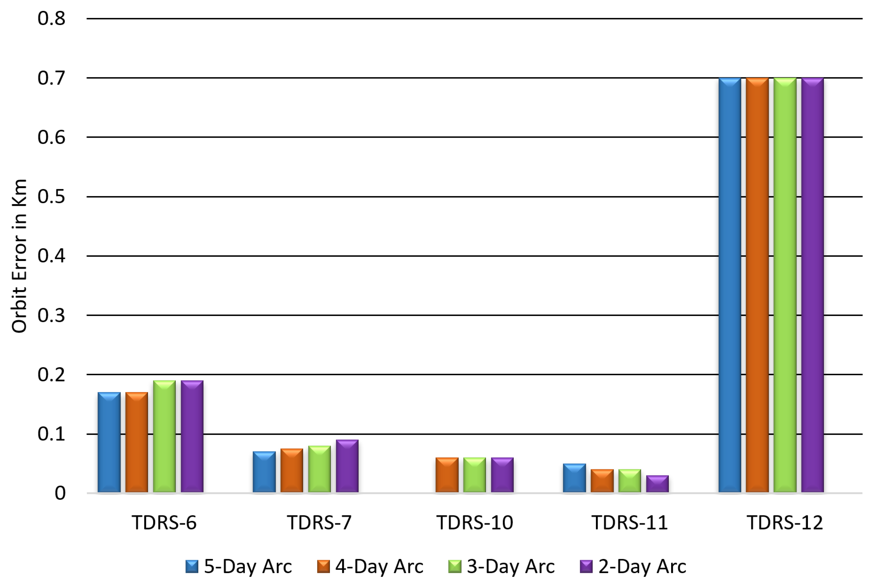
To investigate the impact of arc length on orbit determination accuracy, a study was conducted using the TDRS satellites.
Figure 10 shows the histogram of orbit errors, compared to the operational solution, for different arc lengths ranging from two to five days. The solutions were computed using TT&C-only measurements when measurement bias covariances were fully unconstrained. The study indicates that longer arc lengths generally lead to more accurate orbit determinations. However, for smaller arc lengths, such as two to three days, the solutions sometimes diverged or led to orbit errors up to 38 km primarily due to the overestimation of the range bias.
Another study was carried out to investigate how the length of an arc affects TDRS orbit accuracies when the solutions are constrained. These solutions did not include estimates for TT&C measurement biases, and the bias values were set to zero meters.
Figure 11 shows the histogram of these results. The results indicated that the estimated orbit errors were the same for all arc lengths tested. This suggests that if a TT&C measurement error is constant over time, then a solution with a smaller arc length is sufficient for determining the TDRS position and velocity accurately.
However, when TT&C measurement biases are not considered, the maximum error in the TDRS orbit is the sum of any dynamic error and systematic error in the measurements. The relationship between measurement bias and orbit error can be complicated and depends on factors such as the type of bias, the measurements used, and the orbit determination algorithm employed. It is, therefore, crucial to identify and correct any measurement biases in the TT&C data to obtain reliable and accurate orbit predictions.
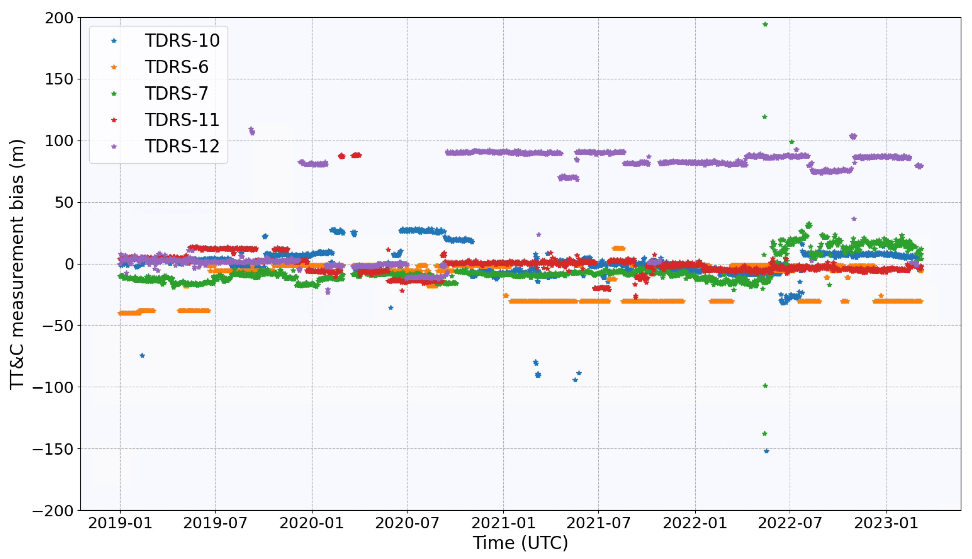
Nevertheless, not accounting for TT&C measurement biases is still a viable choice in these studies compared to overestimating biases. As shown in
Figure 12, estimated TT&C biases were consistently below 50 m for five years except for TDRS-12, where bias consistently remained around 82 m since the late 2020s.
5.2. User Spacecraft Orbit Determination Results
The previous sections have served to establish the range of reasonable uncertainties for TT&C-only TDRS orbits. The main objective of this section is to analyze the impact of DOWD OD precision under circumstances where TDRS precision is solely determined by TT&C tracking in the absence of BRTS replacement (see
Section 2). To achieve this objective, four distinct sets of satellites with varying characteristics were utilized in the investigation (see
Section 4.3). Two separate inquiries were conducted to thoroughly explore the issue.
The first inquiry involved establishing user spacecraft orbits using TDRS orbits based on Scenario 1 and Scenario 2 of
Section 5.1, where the TDRS orbits were derived from operational values. In the second inquiry, a cluster of TDRS ephemerides obtained from scenario 3 of
Section 5.1 was used to obtain a more comprehensive understanding of the relationship between user spacecraft orbit error and TDRS orbit error evolution.
5.2.1. Case #1
Table 3 exhibits the maximum error observed in the user spacecraft’s trajectory relative to the operational solution. The associated discrepancies in the TDRS orbits leveraged to derive these outcomes are displayed in
Table 2. As several TDRS satellites were employed in generating the user spacecraft’s trajectory, the total cumulative TDRS orbit position and velocity discrepancies indicated in
Table 3 were computed as follows:
where
and
is the total cumulative error in position and velocity of the TDRS constellation’s orbits, respectively. The maximum positional errors for each TDRS in the constellation are represented by
,
, and
, while the maximum errors in velocity are denoted by
,
, and
The variable
i identifies the specific TDRS number, where
i can take the values 6, 7, 10, 11, or 12.
According to the findings for all user spacecraft, discrepancies were observed in position and velocity measurements. Among them, LANDSAT-9 recorded a maximum difference of about 50 m in position and 45 mm/s in velocity. In contrast, IXPE showed a considerably lower error with only 16 m and 16 mm/s in position and velocity, respectively.
If accurate accounting of TT&C biases is performed, any discrepancies in the TDRS orbit due to TT&C biases would not have a significant impact on the user spacecraft orbit. Moreover, incorporating more data types or an additional DOWD pass could further enhance a spacecraft’s orbit accuracy.
5.2.2. Case #2
Insufficient knowledge about the TT&C bias and its covariance can lead to significant errors in the orbits of the TDRS satellites. As a result, the user spacecraft’s orbit determination accuracy can be severely affected. Any error in the TDRS orbit can propagate to the user spacecraft orbit and cause substantial errors in the determination of its position and velocity. To illustrate this impact,
Figure 13 demonstrates the impact of the TDRS orbit error on the user spacecraft’s orbit. The plot shows the relationship between the error in the user spacecraft’s orbit and the cumulative error in the TDRS orbit. Each point on the plot represents a unique solution obtained using the TDRS orbits described in
Section 5.1.3. Remarkably, despite being in different orbital configurations, the errors in all user spacecraft’s orbits were linearly related to the errors in the TDRS orbits.
However, the slope of linearity varies for each spacecraft. Several factors could have contributed to this variance, including the relative position of the TDRS with respect to the user spacecraft during the acquisition of DOWD measurements, the number of DOWD passes acquired, and dynamic errors in the user spacecraft’s orbit.
For instance, the LANDSAT-8 spacecraft exhibited a significant error, even for similar cumulative errors in the TDRS orbit. This can be attributed to the limited number of usable DOWD passes. Only three passes were available due to a TDRS maneuver, and one of these was sigma edited out by GTDS because of increasing orbit uncertainties. DOWD generally requires a minimum of four passes for a reasonable orbit solution, as short arcs of data are typically insufficient to provide reliable estimates. As a result of the limited DOWD passes, the estimated LANDSAT-8 solutions were not highly accurate. This situation represents the worst-case scenario in terms of the quality of the solutions obtained.
On the other hand, JPSS-2 exhibited the gentlest slope in the linear relationship with TDRS orbit errors. This can be attributed to the wealth of DOWD passes (16 in total) available for JPSS-2.
Table 4 and
Table 5 provide a summary of the impact of using constrained TT&C bias and unconstrained TT&C bias TDRS solutions on the accuracy of the user spacecraft’s orbit. These tables present uncertainties in position and velocity compared to the operational solution. The constrained bias TDRS solutions were observed to provide significantly better user spacecraft orbit precision than the unconstrained bias TDRS solutions. For instance, the maximum position error in the LANDSAT-8 orbits using a constrained TDRS solution was approximately 293 m, whereas it was ≈33,000 m when using an unconstrained TDRS solution.
The findings suggest that when there is a lack of adequate understanding of the TT&C measurement bias and its covariance, a constrained TDRS solution could offer a more dependable user spacecraft orbit. In these scenarios, a constrained TDRS solution has the potential to mitigate the spread of any errors originating from measurements in the TDRS orbit to the user spacecraft orbit. This leads to more precise determinations of position and velocity compared to an unconstrained solution.
Table 6 presents the mean and standard deviation values of the LOF offset estimated for all one-way Doppler passes. In addition to the TT&C-only solutions’ values, values obtained from the TT&C and BRTS-based operational solutions are also shown for comparison. All spacecraft estimated values were compatible with operational solutions. This compatibility can be attributed to the fact that, when comparing the TT&C-only DOWD solution with the operational solution, the maximum change in user spacecraft velocity concerning the TDRS satellites resulted in a maximum Doppler shift that was significantly smaller than the mean and standard deviation values of the one-way Doppler residuals (see
Table 6). The correlation between Doppler shift and velocity change can be expressed as:
where
represents the Doppler shift in Hertz (Hz),
is the velocity change in meters/second (m/s),
is the S-band reference frequency in Hz, and c is the speed of light in m/s.
For instance, the LANDSAT-8 spacecraft’s maximum deviation in velocity from the operational solution was about 1.6 mm/s, resulting in a maximum Doppler shift of approximately 12 mHz in the S-band. Notably, this value is negligible compared to the mean and standard deviation of the LANDSAT-8 one-way Doppler residuals. Thus, TT&C-only measurements did not significantly alter the user spacecraft velocity with respect to the TDRS satellites enough to affect the accuracy of the LOF offset estimation and yielded an extremely close agreement with the operational values.
6. Discussion
This study investigated how uncertainties in the orbit of the TDRS satellites propagate into the DOWD-based orbit of the user spacecraft when the TDRS orbit is determined solely based on TT&C measurements. The following TDRS orbit determination scenarios were considered:
Reconstruction of the TDRS orbit using current operational values of the a priori conditions.
Monte-Carlo analysis to assess uncertainties in the TDRS orbit reconstruction in the case of inadequate knowledge of the a priori conditions.
Analysis of the relationship between the quality of the TDRS orbit reconstruction and arc length dependency.
Each reconstructed TDRS orbit was used to reconstruct the orbit of the user spacecraft. The error between the reconstructed orbits and operational solutions was evaluated. The FDF’s operational TDRS solution, derived from BRTS and TT&C measurements, achieves an accuracy better than 75 m, whereas the DOWD-based operational solution for user spacecraft reaches an accuracy of up to 300 m.
The study found that the TDRS orbit determined solely from TT&C measurements is highly sensitive to measurement bias and its covariance. If these values are not adequately accounted for during orbit determination, it can result in a significant orbit error of about 17 km. In such cases, extending the arc length of the TT&C measurements by five or more days can improve the estimation of the TT&C bias and result in better orbit determination accuracy.
However, if there is insufficient knowledge of the measurement bias and its covariance, it is recommended to avoid estimating the TT&C bias to prevent substantial orbit errors. In this case, the maximum error in the orbit is directly affected by the underlying error present in the TT&C bias. Consequently, an increase in the magnitude of measurement error will result in a higher level of orbital error.
Therefore, it is important to assess the accuracy of TT&C measurements and consider their associated uncertainties. If the precise values of these quantities are known, the resulting TDRS orbit can be reliable, and the orbit error would be within the current TDRS orbit accuracy requirement.
Likewise, the study showed that uncertainties in the TDRS orbit can propagate into the orbit of the user spacecraft and significantly impact the accuracy of the user spacecraft orbit reconstruction. A linear correlation was discovered between errors in the TDRS and user spacecraft orbits. This correlation’s slope is influenced by several factors, including the number of DOWD passes acquired, the relative position of the TDRS concerning the user spacecraft during the acquisition of DOWD measurements, and dynamic errors in the user spacecraft’s orbit. However, because these factors are highly interrelated, the analysis does not isolate their individual contributions to the correlation slope.
Insufficient number DOWD passes (typically less than four) can lead to significant errors in the user spacecraft’s orbit, with the potential for errors of up to 33 km. However, with sufficient DOWD passes, the accuracy of the TDRS orbit plays a vital role in determining the precision of the user spacecraft orbit. Depending on the TDRS orbit error, the user spacecraft orbit error can range from as little as 16 m to as much as about 5 km.
TDRS orbit accuracy degradation can have severe consequences, particularly for spacecraft with stringent orbit precision requirements. Therefore, research indicated that prematurely discontinuing the Bilateration Ranging Transponder System, BRTS, without a thorough understanding of the TT&C bias and its associated uncertainty might obstruct the attainment of the necessary orbital accuracy for both TDRS satellites and user spacecraft. However, despite the reduced precision of the TDRS and user spacecraft orbit, the estimation of Local Oscillator Frequency drift remains accurate without any noticeable impact.
Furthermore, a TDRS orbit based solely on range-only TT&C could have repercussions that extend beyond a DOWD-based user orbit. This is particularly relevant when tracking human space flights and other robotic spacecraft that regularly rely on space relay data. This paper does not delve into the long-term implications of TDRS orbits in the absence of BRTS tracking, nor does it discuss how long-term inaccuracies in the TDRS orbit might affect the user orbit. These critical questions will be addressed in future publications by the FDF.


