Article

The Optimization Design of Dynamic Similarity for the Ground Experimental System of an Aircraft Launch Unit

1
School of Mechanics and Aerospace Engineering, Dalian University of Technology, Dalian 116023, China
2
Beijing Institute of Machinery Equipment, Beijing 100854, China
3
State Key Laboratory of Structural Analysis, Optimization and CAE Software for Industrial Equipment, Dalian University of Technology, Dalian 116023, China
4
Advanced Technology for Aerospace Vehicles of Liaoning Province, Dalian University of Technology, Dalian 116023, China
5
Chengdu Aircraft Design and Research Institute, Chengdu 610091, China
*
Author to whom correspondence should be addressed.
Aerospace 2025, 12(4), 276; https://doi.org/10.3390/aerospace12040276
Submission received: 22 January 2025 / Revised: 20 March 2025 / Accepted: 21 March 2025 / Published: 26 March 2025
(This article belongs to the Special Issue Advances in Thermal Fluid, Dynamics and Control)

Abstract

:
With the development and exploration of the aircraft missile launch system, more and more new launchers are being investigated to improve the aircraft launch capability. It is not possible that all designs of aircraft weapon systems can be manufactured for testing with actual aircraft. Therefore, the ground launch test system, which can reproduce dynamic characteristics of the actual airborne launcher, is necessary. The design of the experimental system of the ground launcher is limited by the conditions of the ground support and installation, and the comprehensive dynamic characteristics of the whole system need to be simulated. This paper proposed an optimization design method based on multivariable optimization, which can adjust dynamic characteristics of the ground launch test system similarly to the actual airborne state. Through the simulations of the basic dynamic characteristics and the calculation of the dynamic response of the initial and optimized ground experimental system, it can be found that the proposed method can effectively control dynamic characteristics of the launch unit in the ground launcher experimental system similarly to the airborne state. This method can greatly reduce the difficulty in the verification of airborne weapon experiments and improve the effectiveness of such ground experiments.

1. Introduction

Due to their complexity and size limitation, it is difficult to perform dynamic experiments on actual structures every time. Therefore, it is necessary to design similar experimental structures to meet the dynamic similarity requirements in order to obtain the dynamics of the actual structures, which can be reproduced by the experimental structure [1,2]. A common type of dynamic similarity design is the reduced scale model design. Konstantin and Christian [3] proposed a scaled-down wind tunnel model of a delta wing to test the aeroelastic effects of the delta wing in a wind tunnel, and the dimensionless deformation of the scaled-down model did not deviate from that of the real model while ensuring that the first five orders of the modes and reduced eigenfrequencies of the scaled-down model and the real model were similar. Gao et al. [4] used geometric similarity, structural similarity, Reynolds similarity and boundary layer theory to establish a scaled model of large wind turbine blades, which ensures the structural and aerodynamic similarity of the blades. The scaled model reduces the calculation time under the condition of satisfying the calculation error. Cao et al. [5] established the relationship between the natural frequency of the boom and the slenderness ratio of the boom for the dynamic characteristics of a retractable boom, and the experiments on the scaled model showed that this method can predict the dynamic characteristics of the boom very well. Zhang et al. [6] established a similarity law for the dynamics of gravity dams under airburst loading and verified the correctness of the method experimentally. The problem of the similarity of dynamics for simple structures such as plates and shells has also been studied by many scholars [7,8]. Zhou et al. [7] proposed an improved stiffened plate scaling model design method to predict the dynamic response of stiffened plates under impact loading. The results showed that the proposed scaled model design method can predict the impact response of the original model very well. De Rosa et al. [8] used the energy distribution method to model the plate dynamic similarly and verified the correctness of the method with single and combined plates. Due to the complexity of the real structure, using a simplified dynamic similarity model to reflect the dynamic characteristics of the real structure has also been proposed. Zhang et al. [9] simplified the dynamic similarity of a complex aero-engine rotor, and the simplified rotor model can reflect the dynamics of the actual aero-engine rotor well under the condition of satisfying the first three orders of frequency and modal similarity. Zhao et al. [10] proposed a method for designing a strictly dynamically similar model of a rotor considering dynamically similar and constrained stiffness support conditions, using a genetic algorithm to modify key parameters. The optimized rotor dynamic similarity model has a very small error in the first three orders of frequency compared to the real structure.
The dynamic response of structures can be calculated by the modal superposition method [11,12,13]. For example, Yang et al. [14] used the modal superposition method to calculate the response of the structural part of the rocket fairing when calculating the fluid–solid coupling response. Hu et al. [15] calculated the gust response of a flying wing with a large aspect ratio by means of the modal superposition method. Therefore, when designing the dynamic similarity, the low-order frequencies and modes of the dynamic similarity model and the original model should be similar to ensure that the dynamic similarity model can respond to the dynamics of the original model [3,9,10].
It is well known that the design of aircraft and the launching structures do not belong to the same institution sometimes, so the launching load due to the launch unit is analyzed individually to assess the design of the fighter plane design. Because of the complexity of the on-board experiments with the airborne launch unit, ground experiments were conducted prior to the on-board experiments. In order to ensure that the ground experiments can better reflect the dynamics of the launch unit under the conditions of the on-board experiments, it is necessary to ensure that the ground experiments and the on-board experiments exhibit dynamic similarity. If the ground experiments, which employ the same launch unit as the aircraft, can provide a similar dynamic loading environment to feedback the aircraft design, the role of such ground experiments is achieved. Therefore, we adopted the Differential Evolution (DE) algorithm [16,17] to optimize the design of the ground test frame so that the first three orders of frequencies and modes of the launch unit under the ground experimental condition were similar to those under the airborne condition.

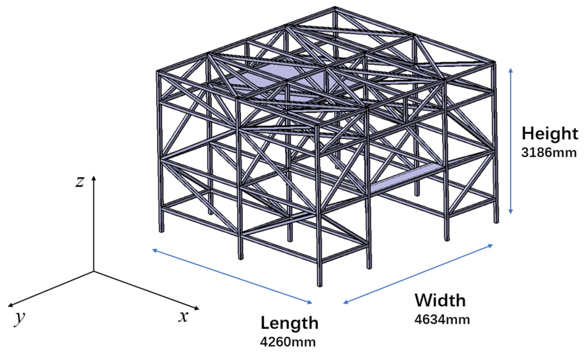
2. Structure of the Ground Launcher System

2.1. The Launcher Model (Without the Launch Unit)

The present launcher structure is a space steel frame structure (see Figure 1), with plates at the location where it is connected to the launch unit by means of a connecting structure.

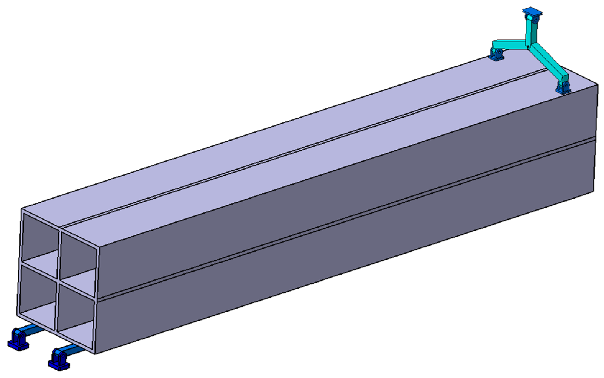
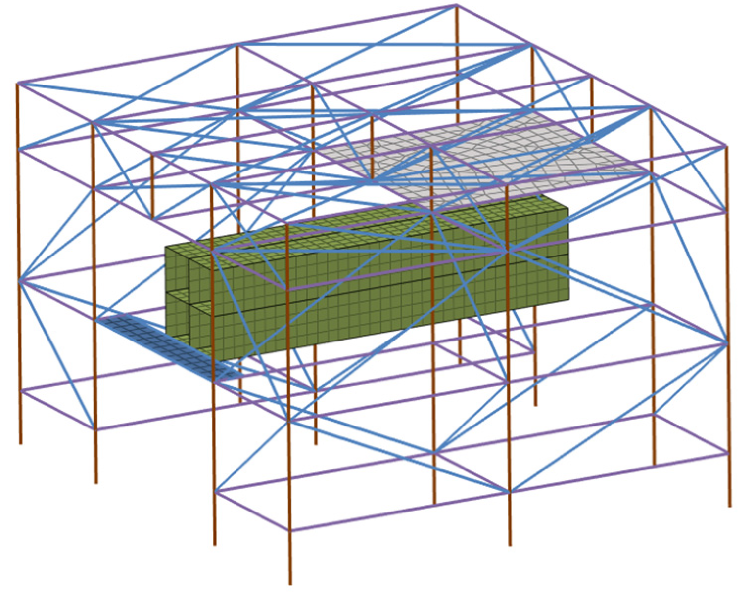
2.2. The Launcher Model (with the Launch Unit)

The launch unit consists of a launch box and a mounting structure (see Figure 2 and Figure 3), and the mounting structure (see Figure 4) is connected to the launcher structure by some joint structures, which can adjust the angle of the launch unit within a certain range, and these mounting structures significantly affect the dynamics of the launch unit and subsequently are the main object of study for the optimization design.

3. Structural Dynamic Characteristics of the Launcher Test System

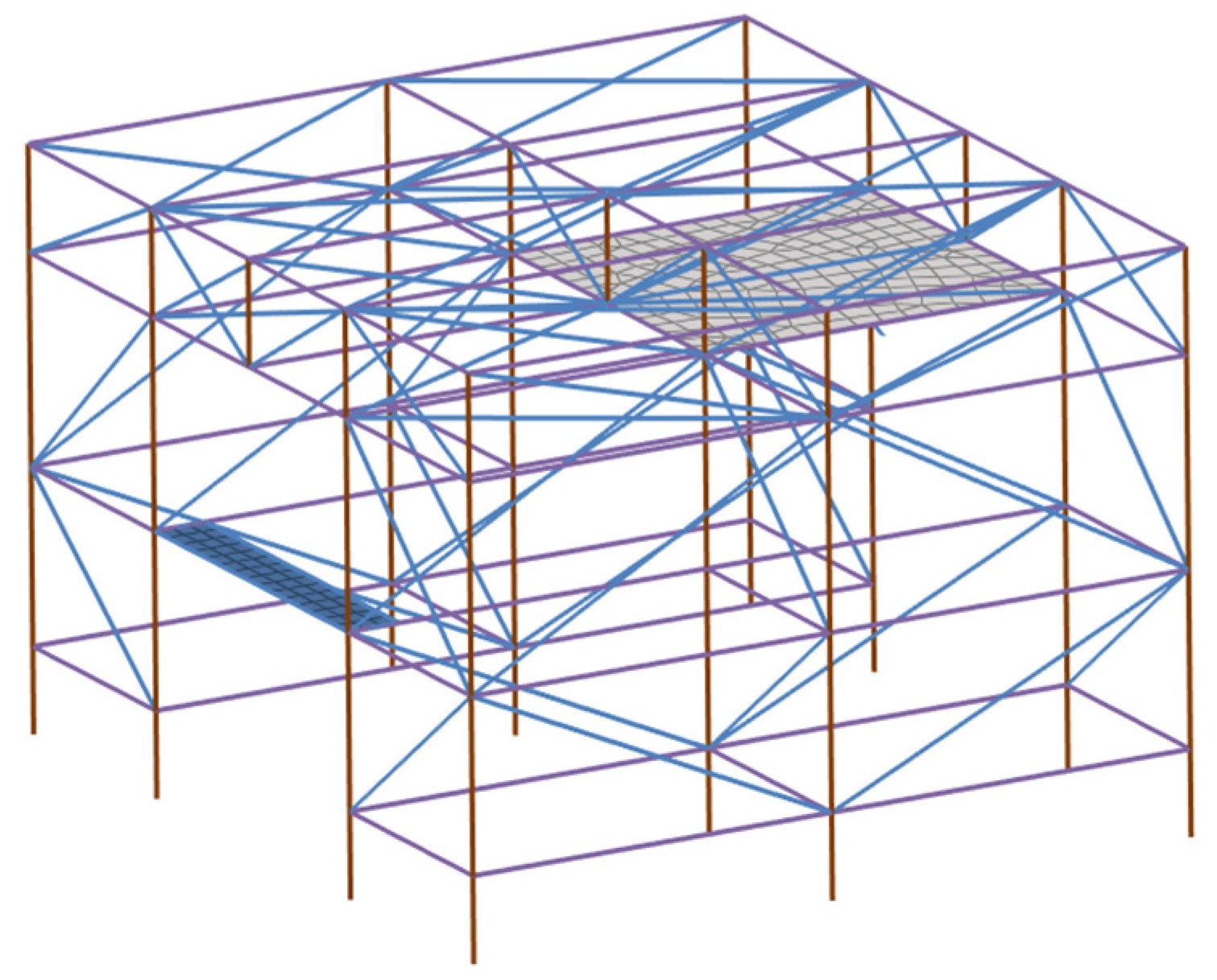
3.1. Structural Dynamic Models

In this paper, finite element models are established for the individual ground launcher (without a launching unit; see Figure 5) and the whole ground launcher test system (see Figure 6) for the analysis of structural dynamics, and the finite element models are introduced as follows.
The launcher and mounting structure are made of beam elements, with the cross-sectional shape shown in Figure 7, and the launch box and connecting plates are made of four-node and three-node shell elements, which are divided into a total of 3940 elements. The material of the launcher and launch unit are steel and aluminum, respectively, and their material parameters are shown in Table 1. The launch unit is a four-channel launch tube square box, which is 3500 mm long, 600 mm wide, 600 mm high, and 20 mm thick and weighs 652 kg.
The structural dynamic control equation for the ground launcher test system is shown in Equation (1).
M x ¨ + C x ˙ + K x = f
where M ,   C , and K are the mass, damping and stiffness arrays of the structure, respectively; x is the nodal displacement vector; and f is the external load.
The bottom of the launcher is fully fixed supported, and by solving the generalized eigenvalue problem shown in Equation (2), natural frequencies and modes of the ground launcher test system can be obtained, as shown in Figure 8 and Table 2 (i.e., fully fixed support), respectively.
K Φ = M Φ Λ Λ = λ 1 0 0 λ N Φ = φ 1 φ N
where Φ represents the eigenvector matrix; Λ represents the eigenvalue matrix; λ j and φ j   j = 1,2 , , N are the j order eigenvalues and eigenvectors; and N is the number of degrees of freedom of the structure.
The first three modes of the ground launcher test system are mainly the yaw, pitch and roll modes of the launcher unit (see Table 2 for the frequency values), but due to the lack of launcher stiffness, as shown in Figure 8, the launcher’s own modes before optimization are influenced by the modes of the whole launcher test system, and the low-order structural dynamics are therefore a mixture of the launcher and the launch unit. This will obviously affect the similarity of the dynamics of the actual launch unit for the aircraft condition versus the ground experimental condition.

3.2. Effect of Different Ground Boundary Conditions

When dynamic characteristics of the launcher test system were obtained in Section 3.1, a fully fixed supported boundary condition was employed at the bottom of the launcher. However, it is difficult to achieve a fully supported boundary at the bottom of the launch system since the launch site ground is not an ideal rigid boundary. Several studies in the field of civil engineering have proved that the ground boundary conditions have an influence on the dynamic characteristics of the frame structures [18,19], so the influence of the ground elasticity effects on the dynamic characteristics of the launch system is investigated in this paper. The elastic effect of the ground was simulated using the Winkler elastic foundation model.
q = K w u
where q is the reaction pressure, K w is the Winkler elastic foundation coefficient, and u is the vertical displacement at a point. Elastic boundary conditions are used in finite element models to simulate the above elastic effects. Different elastic coefficients are used to simulate different ground boundary conditions, and the results of natural frequency calculations for different states are shown in Table 2. The red areas at the bottom of the model in Figure 9a are the elements used to simulate the ground elasticity effects.
Comparing natural modes and frequencies of the ground launcher test system with or without considering the ground effects, it can be seen that the ground elasticity effects have impacts on natural frequencies of the ground-based test system, so the impact on the first three orders of the natural frequencies of the launcher test system cannot be ignored. Natural frequencies of the test system decrease with a reduction in the elasticity coefficient, and the elastic boundary condition of K w   = 45,000 N / m 3 is found to be closer to the measured data of the launcher structure dynamics in this paper. The final choice of boundary condition in this paper is shown in Figure 9a and the first three natural modes of the ground launcher system with this boundary condition are show in Figure 9b–d.

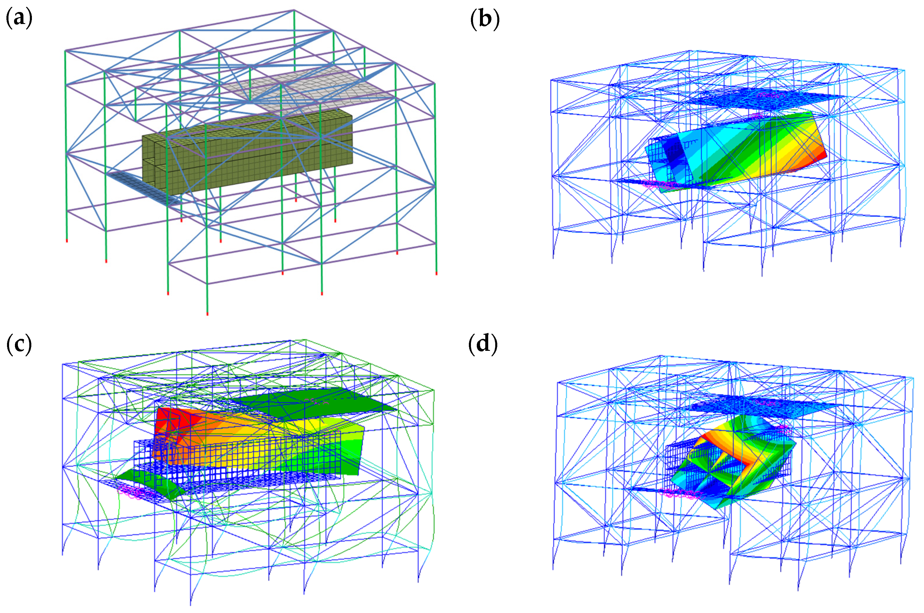
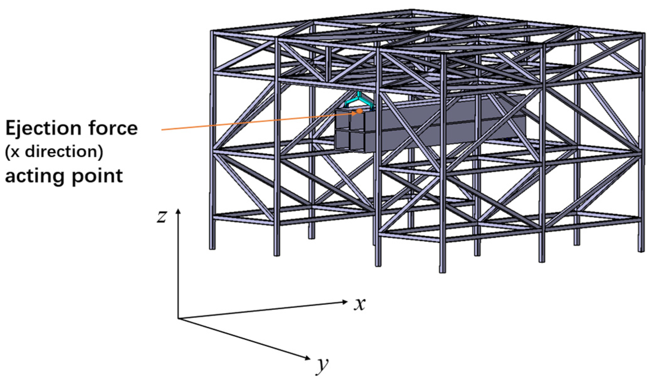
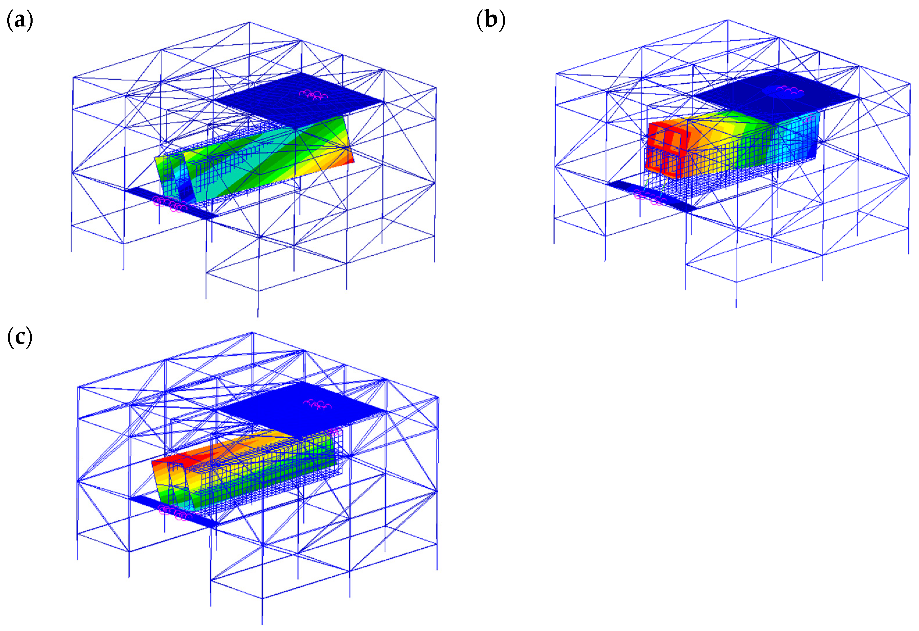
3.3. A Simulation of the Overall Structural Dynamic Characteristics of the Launcher Test System

For the simulation of the dynamic response of the launch system during missile launching, the launcher test system takes into account the ground elasticity effect (i.e., an elastic boundary condition of K w = 45,000 N / m 3 is used).
The ejection force on the launcher test system during launch is shown in Figure 10 [19]. The ejection force is applied to the middle of the upper left channel of the four channels (the point where the ejection force is applied is shown in Figure 11), and two measurement points at the front of the launcher unit (see Figure 12) are selected to observe the displacement time response when calculating the dynamics of the launcher system based on the modal superposition method [15,16]. The results of the calculations are shown in Figure 13 and Figure 14. It is seen that the peak value of the displacement response at measurement point 1 is about 23 mm (i.e., vector sum), and the peak value of the displacement response at measurement point 2 is about 28 mm (i.e., vector sum). This response must be the dynamic response obtained by coupling the vibration characteristics of the launcher and the launch unit, so it is not possible to evaluate the dynamic stability of the launch unit under the airborne condition simply by such a result.

4. Optimization Design Method for Dynamic Characteristics of Launcher Test System

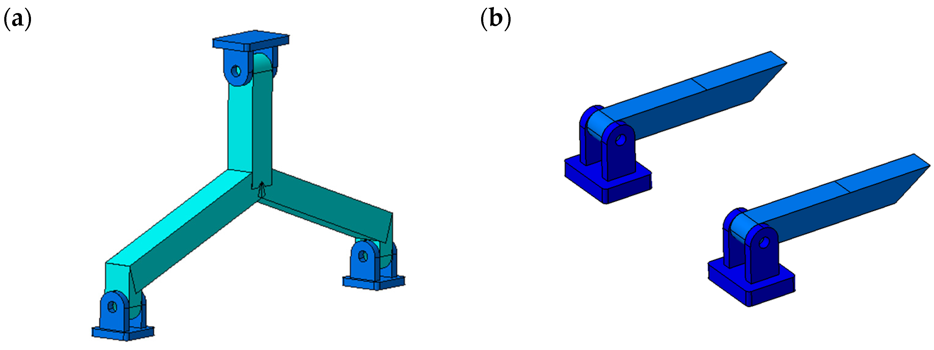
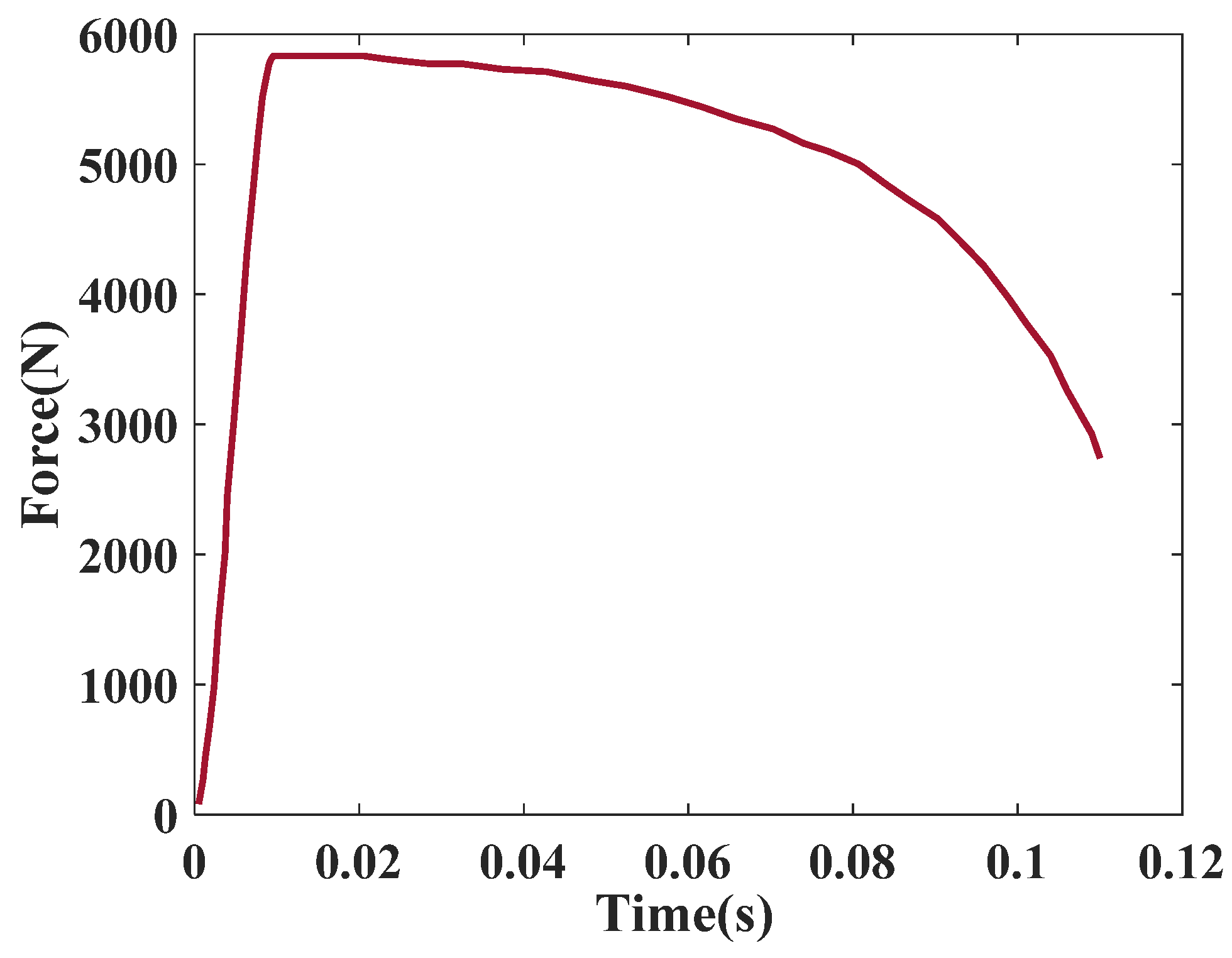
4.1. Structural Dynamics of the Launch Unit in the Airborne State

The launch unit is mounted onto an aircraft model (see Figure 15), and by solving the generalized eigenvalue problem shown in Equation (2), free boundary conditions are employed, and the modes and frequencies of the launch unit in the airborne state can be obtained, as shown in Figure 16 and Table 3, respectively. Natural modes of the launch unit in the airborne state are still manifested as the yaw, pitch and roll of the launch unit. The total weight of the aircraft is about 3900 kg; its span, length and height are 12.8 m, 13.4 m and 3.6 m, respectively. It should be noticed that the aircraft is made of simulated material with a modulus of elasticity of 7 × 10 10   P a .

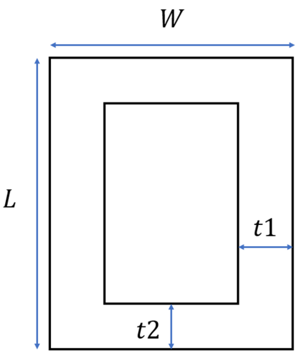
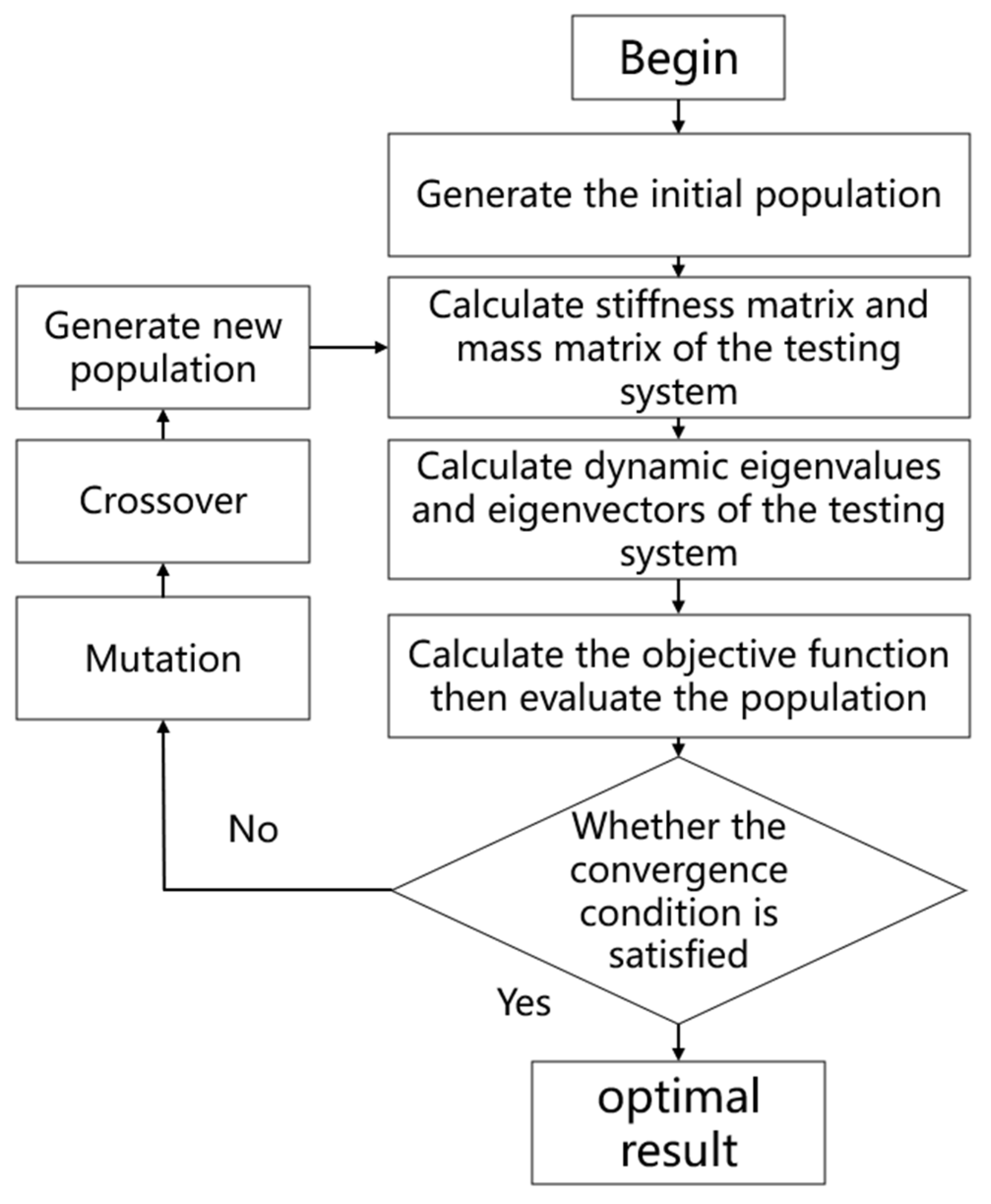
4.2. Optimization Design for the Launcher Test System

For the analysis of the basic dynamic characteristics of the launcher test system in Section 3.3 and Section 4.1, it is seen that the first three modes of the test system have obvious interference with the launcher modes, which affects the simulation results of the dynamic response of the launcher unit and the use of the results during the launch due to the lack of stiffness of the launcher itself. At the same time, the first three order frequencies of the launch test system are lower than those of the airborne state, which also cannot accurately reproduce dynamic characteristics of the launch unit when it is in the airborne state. The following optimization equation is proposed to address the above problems:
F i n d   x i M i n i m i z e   ( ω j ω ¯ j ) s . t .                                                                                                               K φ j = ω j 2 M φ j , j = 1 , n , , N K = K 1 0 0 K 2 m m ¯ K 1 K ¯ 1 x i Χ
where x i represents the optimization design variables; ω j represents the angular frequencies of the launch test system; ω ¯ j represents the circle frequencies of the launch unit in the airborne state; K 1 is the stiffness matrix of the launcher; K 2 is the stiffness matrix of the launch unit; m is the total mass of the test system; m ¯ is the upper limit of the total mass; K ¯ 1 is the lower limit of the launcher’s stiffness; and Χ is the feasible range of the optimization design variables.
The multivariate optimization algorithm used in this study is the Differential Evolution (DE) algorithm, which was proposed by Storn et al. [16]. The main control parameters of the algorithm are the population size NP, the scaling factor F and the probability of crossbreeding CR. The main steps in the algorithm are as follows:
(1)
Randomized generation of initial populations:
The sensitivity of frequency ratio R to the design variables is derived as Equation (5):
x i 0 = x i L + r a n d 0,1 x i U x i L
where x i is the length, width and thickness parameters of the beam section, x i 0 is the matrix of initial values of the length, width and thickness parameters of the beam section, and x i U and x i L are the upper and lower limits of the parameters, respectively.
(2)
Population variation:
v i g + 1 = x r 1 g + F x r 2 g + x r 3 g
where g is the current generation, r 1 ,   r 2 and r 3 are mutually unequal integers, and x r 1 g , x r 2 g   a n d   x r 3 g are the parent individuals.
(3)
Crossover
u i g + 1 = v i g + 1   i f   r a n d 0,1 C R x i g   o t h e r w i s e
We evaluate the new individual after choosing to receive the crossover individual and choose the new individual if it is better; otherwise, we choose the original individual.
x i g + 1 = u i g + 1   i f   f ( u i g + 1 ) f ( x i g ) x i g   o t h e r w i s e
The optimization flow of the ground-based launcher test system using the optimization algorithm in this paper is shown in Figure 17.
The dimensions of the key components of the ground-based launcher test system after the optimized design by the mentioned optimization method are shown in Table 4, and the optimized natural modes and frequencies are shown in Figure 18 and Table 3, respectively.
The first three modes of the optimized ground launcher test system are the yaw, pitch and roll of the launch unit, the modes of the launcher box itself (i.e., the middle box in Figure 2) no longer interfere with the modes of the launcher unit. The maximum difference in the first three mode frequencies of the optimized ground launcher test system is only 6.4% compared with that of the first three orders of the airborne state launch unit, which fully meets the engineering requirements.
The launch ejection force shown in Figure 10 is applied to the optimized ground launcher test system, and the modal superposition method is used to calculate the dynamic response. The displacement time response of measurement points 1 and 2 are shown in Figure 13 and Figure 14, respectively. It is seen that the peak value of the displacement response of measurement point 1 of the optimized ground launcher test system is about 14 mm, and that of point 2 is about 16 mm, which are both reduced evidently compared with the results before optimization. This indicates that the influence of the mode of the launcher on the dynamic response of the launch unit is basically excluded after optimization, and the calculation results at this time are more similar to the airborne state characteristics.
The first six modes of the present airborne state without those of the launch unit in Figure 15 are shown in Figure 17 and the related natural frequencies are also presented. It is seen that the launch unit preserves no interference with the main natural modes of the airborne state. It is well known that the mode superposition method is usually employed to simulate the dynamic response of complex structures. The optimization process in this paper is divided to assess the dynamic response parts due to the launch unit versus the main mode parts of the whole structures (i.e., the airborne state with the launch unit in this paper). After this optimization process, the influence of the dynamic response due to the launch unit can be obtain by the ground experiments. The modes of aircraft are shown as Figure 19, it can de seen that the modes of aircraft are not influenced by the launcher unit.

5. Conclusions

In this paper, structural dynamics of a ground launcher test system is simulated and analyzed. The influence of different boundary conditions on the simulation model of the launcher is discussed. Taking a specific airborne launch state as a sample, an optimization design method of the ground launcher test system is proposed, designing an effective model with similar dynamic characteristics to the airborne state. The following is concluded:
(1)
Dynamic characteristics of the ground launcher test system relies on an accurate simulation model. Different ground boundary conditions are investigated in this paper in order to find an accurate simulation model to obtain useful dynamic characteristics for the ground launcher test system.
(2)
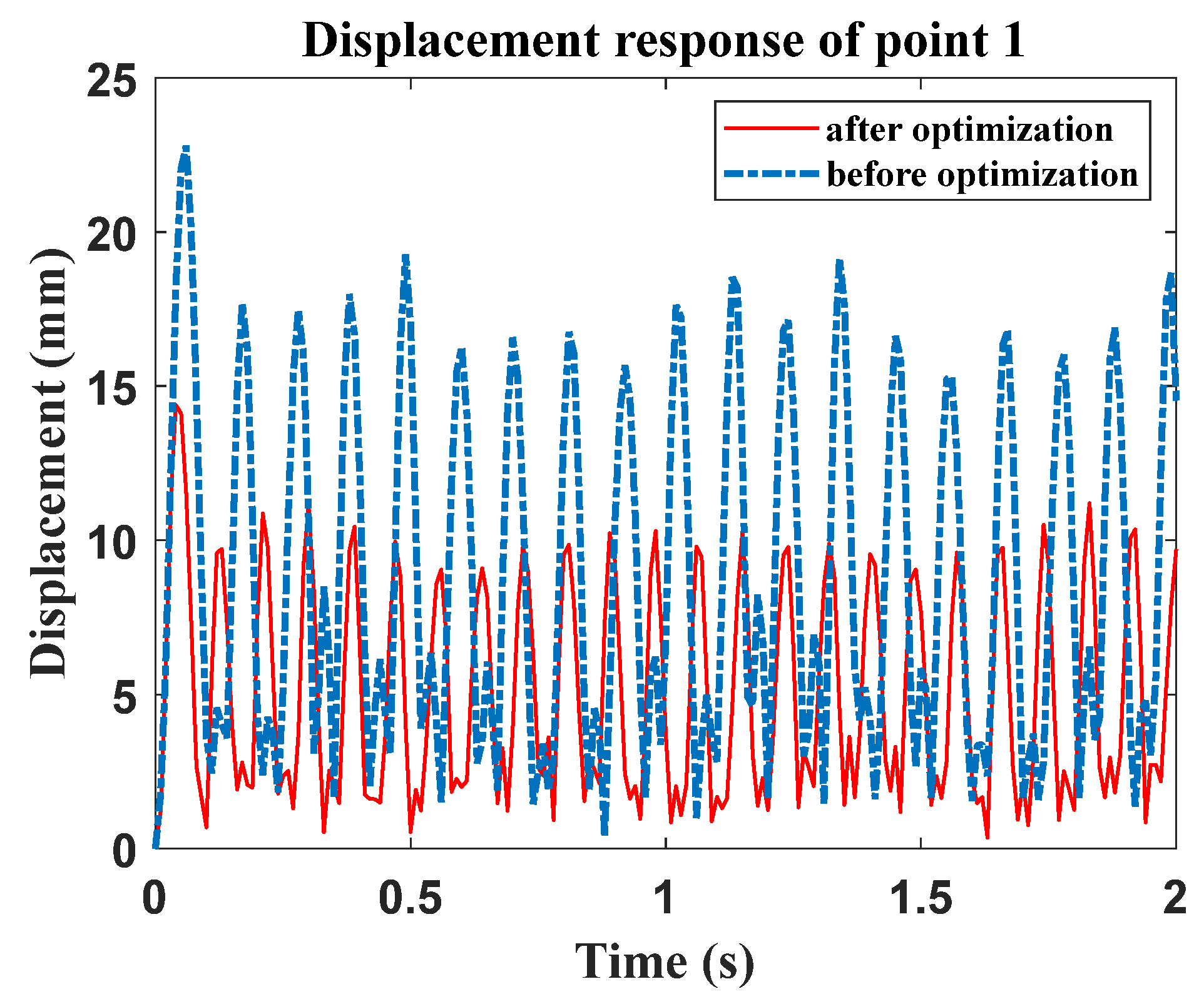
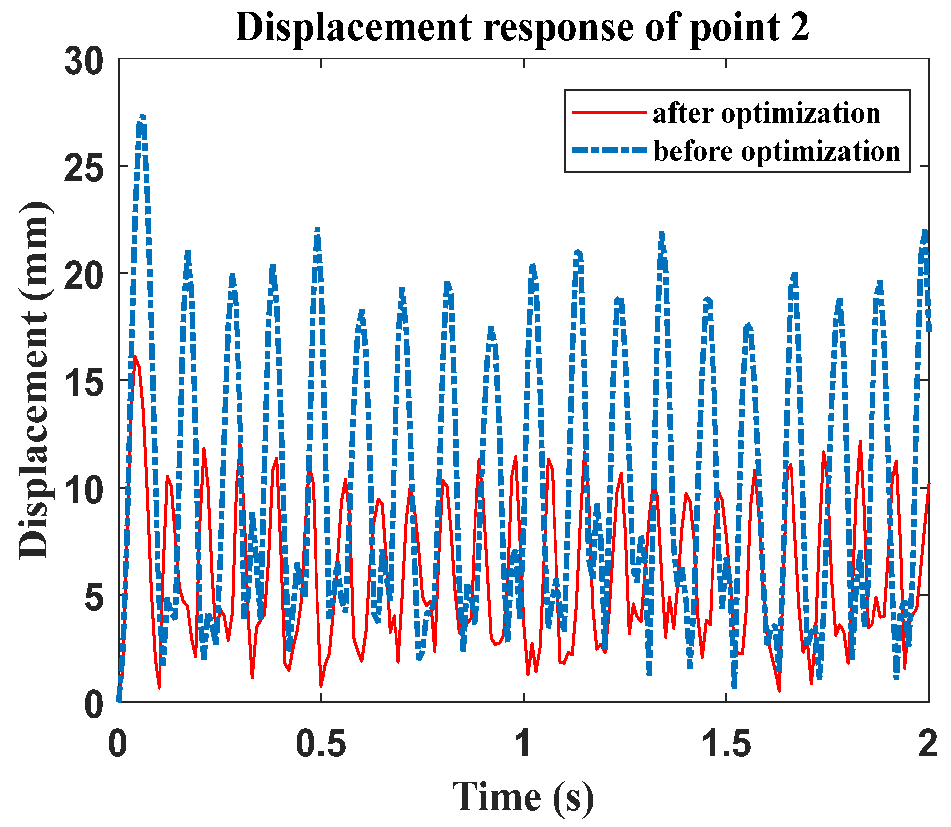
An optimization design method for the ground launcher test system is proposed in this paper based on the consideration of the overall structural dynamic characteristics. Natural frequencies of the present launcher structures increase with the optimized design, meaning that they do not participate in the main vibration response of the launching unit. This does not influence the design effectiveness of testing missile launcher units when they are employed for ground launcher vibration experiments.
(3)
For ground experiments of airborne missile launches, an effective structural dynamic optimization method can be used to obtain structural dynamic similarity via the airborne state; thus, it is necessary to verify the airborne launch conditions through ground launching tests.
The optimization design method proposed in this paper, which is based on the effective dynamic numerical simulation model, can provide realizable ground launch test system design for different airborne missile launch system configurations. It provides an effective guarantee for the ground test verification method of the airborne missile launch system; thus, it can provide important potential applications for research into new airborne missile launch systems.

Author Contributions

Conceptualization, Y.B. and S.Z.; methodology, Y.B., S.Z., L.C. and H.H.; software, Y.C.; validation, Y.B. and X.Z.; writing—review and editing, Y.B. and X.Z. All authors have read and agreed to the published version of the manuscript.

Funding

This research received no external funding.

Data Availability Statement

Data are contained within the article.

DURC Statement

The research complies with all applicable local laws and institutional ethics guidelines. The re-search has been cleared for public dissemination. The work does not involve any sensitive, clas-sified, or restricted military technology.

Conflicts of Interest

The authors declare no conflicts of interest.

References

  1. Coutinho, C.P.; Baptista, A.J.; Rodrigues, J.D. Reduced scale models based on similitude theory: A review up to 2015. Eng. Struct. 2016, 119, 81–94. [Google Scholar] [CrossRef]
  2. Filippou, E.; Kilimtzidis, S.; Kotzakolios, A.; Kostopoulos, V. Towards Structural and Aeroelastic Similarity in Scaled Wing Models: Development of an Aeroelastic Optimization Framework. Aerospace 2024, 11, 180. [Google Scholar] [CrossRef]
  3. Bantscheff, K.; Breitsamter, C. Dynamic Structural Scaling Concept for a Delta Wing Wind Tunnel Configuration Using Additive Manufacturing. Aerospace 2023, 10, 581. [Google Scholar] [CrossRef]
  4. Gao, G.; Shu, H.; Yi, Z.; Yang, S.; Dai, J.; Zhang, F. A Scaled Numerical Simulation Model for Structural Analysis of Large Wind Turbine Blade. Energies 2024, 17, 4849. [Google Scholar] [CrossRef]
  5. Cao, X.; Wang, Z.; Wang, W.; Dong, X. Application of Similarity Theory for Dynamic Characteristics Prediction of Crane Flexible Truss Boom. Math. Probl. Eng. 2020, 2020, 4273810. [Google Scholar] [CrossRef]
  6. Zhang, K.; Lu, F.; Peng, Y.; Li, X. Study on dynamic response of gravity dam under air blast load based on similarity law. Eng. Fail. Anal. 2022, 138, 106225. [Google Scholar] [CrossRef]
  7. Zhou, H.; Okada, T.; Kawamura, Y.; Wang, D.; Hayakawa, G. Improved Similarity Law for Scaling Dynamic Responses of Stiffened Plates with Distorted Stiffener Configurations. Appl. Sci. 2024, 14, 6265. [Google Scholar] [CrossRef]
  8. De Rosa, S.; Franco, F.; Polito, T. Structural similitudes for the dynamic response of plates and assemblies of plates. Mech. Syst. Signal Process. 2011, 25, 969–980. [Google Scholar] [CrossRef]
  9. Zhang, H.; Wang, L.; Wang, A. Vibration response analysis of gas generator rotor system with squeeze film damper based on dynamic similarity. Results Eng. 2023, 20, 101618. [Google Scholar] [CrossRef]
  10. Zhao, R.; Jiao, Y.; Qu, X. Scaling design strategy for experimental rotor systems subjected to restricted support stiffness. Appl. Math. Model. 2022, 109, 265–282. [Google Scholar] [CrossRef]
  11. Fan, X.; Liang, J.; Wang, K.; Zhou, H. Parallel Calculation of Random Vibration for Reentry Vehicles in Fluctuating Pressure Environment. Shock Vib. 2021, 2021, 6864973. [Google Scholar] [CrossRef]
  12. Guo, L.; Ge, J.; Liu, S. Analysis of Vibration and Acoustic Characteristics of a Simply Supported Double-Panel Partition under Thermal Environment. Shock Vib. 2020, 2020, 5613232. [Google Scholar] [CrossRef]
  13. Liu, J.; Sun, X.; Zhang, X.; Hou, X. Research on torsional vibration characteristics of reciprocating compressor shafting and dynamics modification. Mech. Adv. Mater. Struct. 2020, 27, 687–696. [Google Scholar] [CrossRef]
  14. Yang, Z.; Yang, C.; Zhao, J.; Wu, Z. Fluid–Structure Interaction Dynamic Response of Rocket Fairing in Falling Phase. Aerospace 2022, 9, 741. [Google Scholar] [CrossRef]
  15. Hu, Y.; Dai, Y.; Wu, Y.; Yang, C. Time-Domain Feedforward Control for Gust Response Alleviation Based on Seamless Morphing Wing. AIAA J. 2022, 60, 5707–5722. [Google Scholar] [CrossRef]
  16. Storn, R.; Price, K. Differential Evolution—A Simple and Efficient Heuristic for global Optimization over Continuous Spaces. J. Glob. Optim. 1997, 11, 341–359. [Google Scholar] [CrossRef]
  17. Moosavian, H.; Mesbahi, P.; Moosavian, N.; Daliri, H. Optimal design of truss structures with frequency constraints: A comparative study of DE, IDE, LSHADE, and CMAES algorithms. Eng. Comput. 2021, 39, 1499–1517. [Google Scholar] [CrossRef]
  18. Bozyigit, B.; Bozyigit, I.; Prendergast, L.J. Analytical approach for seismic analysis of onshore wind turbines considering soil-structure interaction. Structures 2023, 51, 226–241. [Google Scholar] [CrossRef]
  19. Kardooni, M.R.; Shishesaz, M.; Moradi, S.; Mosalmani, R. Free Vibrational Analysis of a Functionally Graded Five-Layer Sandwich Plate Resting on a Winkler Elastic Foundation in a Thermal Environment. J. Compos. Sci. 2022, 6, 325. [Google Scholar] [CrossRef]
Figure 1. The model of the launcher structure.
Aerospace 12 00276 g001
Figure 2. The model of the present launch unit.
Aerospace 12 00276 g002
Figure 3. The model of the launching test system with the launch unit: (a) axonometric view; (b) front view.
Aerospace 12 00276 g003
Figure 4. The model of the mounting structure for the launch unit: (a) rear; (b) front.
Aerospace 12 00276 g004
Figure 5. A simulation model of the launching test system without the launch unit.
Aerospace 12 00276 g005
Figure 6. A simulation model of the launching test system with the launch unit.
Aerospace 12 00276 g006
Figure 7. Beam section of launcher.
Aerospace 12 00276 g007
Figure 8. Natural modes of the launching test system before optimization: (a) the 1st order of the ground experimental structure without the launch unit; (b) the 1st order; (c) the 2nd order; (d) the 3rd order.
Aerospace 12 00276 g008
Figure 9. FEM modelling of launching test system (a) with ground elastic effect; and dynamic modes ( K w = 45,000 N / m 3 ): (b) 1st order, (c) 2nd order, (d) 3rd order.
Aerospace 12 00276 g009
Figure 10. Reaction force on the launch unit during missile launching.
Aerospace 12 00276 g010
Figure 11. Ejection force acting point.
Aerospace 12 00276 g011
Figure 12. Response measurement points.
Aerospace 12 00276 g012
Figure 13. Displacement response of point 1 before and after optimization.
Aerospace 12 00276 g013
Figure 14. Displacement response of point 2 before and after optimization.
Aerospace 12 00276 g014
Figure 15. The modelling of the launch unit in the airborne state.
Aerospace 12 00276 g015
Figure 16. Natural modes of the launch unit in the airborne state: (a) the 1st order; (b) the 2nd order; (c) the 3rd order.
Aerospace 12 00276 g016
Figure 17. The optimization process of the present launch system.
Aerospace 12 00276 g017
Figure 18. Dynamic natural modes of the launching test system after optimization: (a) the 1st order; (b) the 2nd order; (c) the 3rd order.
Aerospace 12 00276 g018
Figure 19. The first six natural modes of the airborne state.
Aerospace 12 00276 g019
Table 1. Material parameters.
MaterialElasticity/GPaPoisson RatioDensity/(kg·m−3)
Al700.302800
Steel2100.337800
Table 2. Results of natural frequency (Hz) for different states.
ModeSimulation ResultsExperimental Results
Fully Fixed Support K w = 105,920 (N/m3) K w = 45,000
( N / m 3 )
18.718.598.458.43
29.869.799.709.66
310.5310.3610.2010.17
Table 3. Comparison of natural frequencies of launch system. (before, after optimization and onboard state).
ModeState of the Ground Experiment/HzAirborne State/HzDifference Before OptimizationDifference After
Optimization
Before
Optimization
After
Optimization
18.459.969.329.3%6.4%
29.7011.8512.3521.5%4.2%
310.2016.0216.6236.3%3.7%
Table 4. Comparison of connecting structures between original and optimized sizes.
Structural ParametersBefore Optimization (mm)After Optimization (mm)
Width W 1 of front mounted structure20.0076.16
Height L 1 of front mounted structure20.0030.58
Thickness t 1 of front mount structure5.006.38
Thickness t 2 of front mount structure5.003.70
Width W 1 of rear mounted structure30.0030.04
Height L 1 of rear mounted structure30.0088.34
Thickness t 1 of rear mount structure6.004.39
Thickness t 2 of rear mount structure6.003.79
Thickness t of upper connection plate30.0035.43
Thickness t of lower connection plate30.0016.92
Disclaimer/Publisher’s Note: The statements, opinions and data contained in all publications are solely those of the individual author(s) and contributor(s) and not of MDPI and/or the editor(s). MDPI and/or the editor(s) disclaim responsibility for any injury to people or property resulting from any ideas, methods, instructions or products referred to in the content.

