Abstract
This study explored methods used to improve the ignition efficiency of a microwave radiation igniter; experimental analyses were conducted to characterize the device’s performance in a model combustion chamber. High-speed imaging combined with an image intensifier tracked flame kernel formation and propagation dynamics under varying airflow rates, residual gas coefficients, and microwave pulse parameters. The results demonstrate that increased airflow rates reduced the relative decline in ignition delay time under microwave application, with the flame area growth curve exhibiting a steeper slope compared to non-microwave conditions. Elevated residual gas coefficients enhanced the microwave-induced reduction in ignition delay time, though this effect weakened significantly in fuel-rich environments. Additionally, higher microwave pulse frequencies and peak power levels both contributed to shorter ignition delay times; the delay decreased linearly with the rising pulse frequency and followed a power-dependent reduction trend. These findings systematically quantify the synergistic effects of flow dynamics, residual gases, and microwave parameters on ignition performance.
1. Introduction
Traditional ignition technology in aircraft engines typically employs spark plugs to generate electric sparks that ignite the fuel-air mixture. However, this ignition method has a narrow ignition boundary and is significantly affected by the aircraft’s flight speed and altitude. Once an engine stalls at a high altitude, it becomes difficult to achieve a secondary ignition restart, often requiring a descent to a lower altitude for a successful ignition. In recent years, microwave plasma ignition technology has gradually developed. Among these advancements, microwave-assisted spark plug ignition combines the advantages of traditional spark plugs and plasma ignition technology, demonstrating strong practical applicability.
Research on microwave-assisted spark plug ignition began relatively early. Institutions such as the University of California, Berkeley, Imagineering Inc. in Japan, and the Korea Advanced Institute of Science and Technology (KAIST) have conducted a series of numerical simulations and experimental studies on microwave-assisted spark plug ignition.
In 2009, Yuji Ikeda [1] et al. of the Imagineering Company in Japan proposed a new technology of generating plasma using spark discharge and microwave, namely microwave-assisted spark plug discharge, to generate plasma. Microwave-enhanced plasma ignition increased the lean burn limit of gasoline from 19.3 to 24.1. In 2011, Defilippo [2] et al. of the University of California, Berkeley, conducted a lean burn ignition experiment on a single cylinder engine using a coupled spark plug from the Imagineering Company in Japan. The microwave feed accelerated the formation of initial ignition nuclei and quickly reached the critical flame size. In 2013, Wolk [3] et al. at the University of California, Berkeley, used a constant volume bomb with a volume of 1.45 L to conduct a comparative study of the ignition and combustion characteristics of methane–air mixtures under different ambient pressures and different equivalence ratios of mixed gases under the ignition modes of traditional spark plugs and microwave-assisted spark plugs. In 2016, Joonsik Hwang [4] et al. at the Korea Advanced Institute of Science and Technology conducted an experimental study on the influence of microwave radiation plasma ignition on the development of laminar flames of acetylene–air mixtures using a constant volume combustion bomb with a volume of 1.4 L. In 2016, Srinivas Padala [5] et al. studied the influence of microwave-assisted plasma ignition on unsteady, expanding, premixed propane–air flames using schlieren technology in a ridge-shaped constant volume combustion chamber under different equivalence ratios of mixed gases and different microwave radiation times.
Chinese researchers initiated their studies on microwave-assisted spark plug ignition relatively late. Zhang Xinwen et al. [6,7,8] conducted a series of numerical simulations and experimental investigations on microwave-assisted spark plug ignition. The experimental results indicate that the enhancement effect of microwaves on ignition primarily facilitates the development of the initial flame kernel, with no significant impact on the later stages of flame propagation. Wang Zhihao et al. [9] performed experimental studies on methanol under various environmental conditions and microwave parameters, revealing that increasing both microwave power and frequency contributes to methanol ignition. Moreover, delayed microwave introduction was found to have a more pronounced enhancement effect on methanol ignition compared to early introduction. Liu Chaohui et al. [10] innovatively incorporated an electrical diagnostic system to analyze the electrical properties during the microwave-assisted ignition process. From the perspective of microwave energy flow, they explored the influence of microwave characteristics on the ignition process of ammonia/hydrogen fuel, discovering that the range of ignition equivalence ratios could be further expanded, and the hydrogen blending ratio could be further reduced.
Previous studies have primarily focused on investigating the single-factor influence of microwaves on the combustion development process, which is insufficient to comprehensively reflect the impact of microwaves on ignition characteristics. As the flight environments of aircrafts become increasingly harsh, the demand for research on ignition characteristics has grown significantly. Although microwave radiation ignition offers numerous advantages, such as enhanced ignition performance, there remains a substantial gap in research regarding its effects on ignition characteristics.
This study utilizes advanced technological methods to capture flame combustion images and analyzes the image characteristics to reflect ignition properties. To investigate the ignition characteristics of microwave radiation igniters, exploratory research was conducted in a model combustion chamber, where non-premixed aviation kerosene–air mixtures were ignited using microwave radiation igniters. High-speed photography and image-intensified flame self-luminescence imaging techniques were employed to capture the formation of flame kernels and the propagation of flames during the ignition process within the model combustion chamber. This study analyzed the effects of various factors, including different air medium flow rates, equivalence ratios, microwave pulse frequencies, and microwave pulse peak power levels, on the formation of flame kernels, flame propagation processes, and ignition delay characteristics.
By systematically examining these parameters, this research aimed to provide a deeper understanding of the influence of microwave radiation on ignition behavior, addressing the existing gaps in the field and contributing to the development of more reliable ignition systems for challenging flight conditions.
2. Experimental System
2.1. Experimental System and Testing Equipment
The experimental system for the ignition characteristics of the microblog radiation igniter is relatively complex, and one of the difficulties is the timing control of the gas supply, oil supply, microwave emission, and igniter discharge. Therefore, it is particularly important to set up the experimental system reasonably to achieve the experimental goal. As shown in Figure 1, the experimental system for the ignition characteristics of the microblog radiation igniter consists of a gas supply system, an oil supply system, an ignition timing control system, a microwave emission system, an igniter power supply system, a model combustion chamber system, and a shooting and recording system.
Figure 1.
Experimental system for ignition characteristics of microwave radiation igniter.
The gas supply system consists of a variable-frequency screw air compressor, a gas storage system, a refrigerated dryer, filters, a gas flow controller, a gas mass flow controller, and connecting pipes. A screw air compressor is used as the gas source, with a power rating of 22 kW, a maximum discharge pressure of 0.8 MPa, and a rated discharge flow rate of 3.6 m3/min. The gas storage system comprises four parallel gas storage tanks, each with a volume of 1 m3 and a rated pressure of 0.8 MPa. The refrigerated dryer, model HL-3ANF, has a power rating of 0.89 kW and an air handling capacity of 3.8 Nm3/min.
A CS230A gas mass flow controller is employed to regulate the air inflow rate. This mass flow controller features digital signal display, enabling real-time flow rate monitoring and control. It effectively reduces flow fluctuations caused by pressure variations in the incoming air, offering advantages such as stable operation, high accuracy, and fast response. These characteristics meet the gas supply requirements for the experiments. All components are connected using airtight pipes, and a leak check is performed prior to use to ensure system integrity.
The oil supply system mainly consists of a mobile oil supply truck, a small air compressor, a solenoid valve, and a Danfoss fuel injection nozzle, which were designed independently by the laboratory. The fuel delivery rate is controlled through precise adjustment of the fuel tank pressure and nozzle orifice dimensions. A KRACHT gear-type flowmeter, characterized by a measurement range of 16 L/min and an accuracy of ±0.3%, is employed to quantify the fuel flow rate. The spray system exhibits a well-defined conical dispersion pattern with a cone angle of 60°.
The ignition timing control system is used for precise control of the action timing of each part in the ignition characteristic experiment of the microwave radiation igniter, achieving precise and orderly progress of the experimental steps and synchronous coordination between various measurement and acquisition devices; the entire ignition process exhibited a duration of 5 s.
The model combustion chamber system consists of an air inlet section, a combustion chamber, an exhaust section, and a head swirl cup. The structural schematic and installation diagrams are shown in Figure 2. The combustion chamber is a combustion chamber modeled based on the characteristic dimensions of the CFM56 combustion chamber. The internal dimensions are a length of 255 mm, width of 125 mm, and height of 130 mm. In order to facilitate optical measurement, a quartz glass porthole is set on one side of the combustion chamber, with one end for air intake and one end for exhaust. The air inlet section is a round tube, and the exhaust section is set up as a square-to-round transition section. The exhaust port is a convergent structure, and the head swirl cup is installed at the inlet of the model combustion chamber’s air inlet end. An image intensifier with a filter is used to collect self-illuminated images of CH radicals in the flame.
Figure 2.
Model combustion chamber system.
2.2. Experimental Conditions and Research Methods
2.2.1. Experimental Conditions
The residual gas coefficient of the combustion chamber is usually defined as the ratio of the actual air flow to the theoretical air flow required for fuel combustion, which is shown as follows:
In the formula, Wa is the actual air mass flow entering the combustion chamber, Wf is the fuel mass flow, and L0 is the air mass flow required for the complete combustion of each kilogram of fuel. In the experiment, RP-3 aviation kerosene was used, and L0 = 14.7 kg/kg.
When conducting experiments on the ignition characteristics of the microwave radiation igniter in the model combustion chamber, the parameters that need to be controlled include the air flow rate Wa of the combustion chamber, the aviation kerosene fuel supply Wf, the microwave pulse peak power P, the microwave pulse frequency f, the residual gas coefficient α, and the mixture temperature T. In order to conduct experimental research on the ignition characteristics of the microwave radiation igniter under different air flow rates in the combustion chamber, the residual gas coefficient is kept constant by regulating the aviation kerosene fuel supply, thereby eliminating the change in the residual gas coefficient caused by changes in air flow rate, while keeping other parameters unchanged. In order to conduct experimental research on the ignition characteristics of the microwave radiation igniter under different residual gas coefficients, the air flow rate is kept constant, and the residual gas coefficient is changed by regulating the aviation kerosene fuel supply, while keeping other coefficients unchanged. In order to conduct experimental research on the ignition characteristics of the igniter under different microwave parameters, the air flow rate and aviation kerosene fuel supply in the combustion chamber are kept constant, and microwave with different pulse peak power and different pulse frequency is output by adjusting the parameters of the microwave power supply. The experimental working conditions of the microwave radiation igniter in the model combustion chamber are shown in Table 1.

Table 1.
Experimental conditions for the ignition characteristics of the microwave radiation igniter.
2.2.2. Experimental Research Methods
- ①
- Ignition delay time
When the temperature of the gas–oil mixture in the combustion chamber reaches its ignition temperature, the mixture cannot immediately undergo a violent combustion reaction. This phenomenon is called ignition delay, and the ignition delay time is an important parameter that reflects the performance of the ignition device. Since the combustion reaction is a complex physical and chemical process, there is currently no unified standard for defining the ignition delay time. During the pyrolysis of aviation kerosene in combustion, substantial amounts of CH radicals are generated [11]. The electronic transition (A2Δ → X2Π) of these radicals produces characteristic emission spectra, with the spectral line at 431.4 nm serving as a definitive signature of the CH radical chemiluminescence band. Therefore, by using an image intensifier with a CH radical filter to capture the formation of a fire kernel and the propagation process of a flame during the ignition process of a microwave radiation ignition device, and by calculating the average gray value of each flame image, the ignition delay time is defined as the time interval from the moment when the average gray value of the flame image begins to increase to the moment when the average gray value of the flame image first reaches the peak value. As shown in Figure 3, when the air flow rate Wa of the combustion chamber is 600 L/min, then the residual gas coefficient α is 1, the inlet temperature T is 300 K, the output voltage U of the driving power supply is 27 V, the output current I is 3.5 A, and the microwave peak power P is 0 W; the grayscale value curve of the flame image collected by the image intensifier during the ignition process of the igniter is shown. According to the definition of ignition delay time, the ignition delay time is 26 ms at this time.
Figure 3.
Definition of the ignition delay time of the microblog radiation igniter.
- ②
- Calculation of flame area value
To calculate the flame area value during the ignition process of the microblog radiation igniter, the image processing function embedded in MATLAB R2022b is used to process each frame of the flame image, filter out noise in the image, enhance the contrast of the image, and finally perform threshold segmentation on the image with a threshold value of 0.3.
3. Discussion of the Experimental Results
3.1. Ignition Process of Microblog Radiation Igniter
Figure 4 shows the change in average gray value of flame images in the model combustion chamber during the ignition process of the microblog radiation igniter under the conditions of air flow rate Wa = 600 L/min, aviation kerosene supply Wf = 0.029 L/min, residual gas coefficient α = 2, microwave pulse peak power P = 0 W, and gas–air mixture temperature T = 300 K. The zero moment in the graph is when the spark is generated. It can be seen that, after the ignition device starts working, the average gray value of the flame images in the model combustion chamber quickly increases to 7.3. Then, with the production of sparks, the average gray value of the flame images in the model combustion chamber fluctuates around 7 and remains at 175.5 ms, which is the stage of fire kernel formation. At 176 ms, the average gray value rapidly increases, reaching its strongest at 203 ms, which is the stage of flame propagation. After that, the average gray value of flame images gradually decays, and fluctuates around 9.5.
Figure 4.
Average gray value change of the flame image in the combustion chamber during the ignition of the microblog radiation igniter.
Lacaze [12] divided the ignition process of non-premixed flames into four stages based on the numerical results of the large eddy simulation: the generation stage of the flame kernel, the propagation stage of the quasi-spherical flame, the upstream propagation stage of the flame, and the propagation stage of the edge flame. By combining the changes in the average grayscale value of the flame image in the model combustion chamber and referring to the research results of Lacaze, it was found that the generation stage of the flame kernel and the propagation stage of the quasi-spherical flame were very short and difficult to distinguish. Therefore, the ignition process of the microwave radiation igniter was divided into the formation stage of the flame kernel, the propagation stage of the flame, and the stable stage of the flame.
Figure 5 shows the images captured by a high-speed camera during the formation of the fire core at a frame rate of 2000 fps. It can be seen that at 0 ms, the ignition coil energy storage capacitor releases energy, and then it discharges and breaks down the mixed gas to generate an electric spark, forming a high-temperature, high-pressure plasma. The mixed gas near the igniter electrode is quickly ignited, and as the capacitor energy is released, the brightness of the spark rapidly decays. Subsequently, due to the driving of the fluid in the recirculation zone of the combustion chamber of the model, the high-temperature region gradually separates from the igniter electrode and moves upstream. Due to the stretching effect of the fluid, the shape of the fire core changes continuously during the motion process. At 0.5 ms, the fire core is basically separated from the electrode, and no obvious quasi-spherical flame development stage is observed. During the initial stage of the formation of the fire core, due to the effects of turbulence mixing and turbulence diffusion, the fire core cannot be ignited successfully in this stage, resulting in repeated ignition and extinction until sufficient energy is accumulated near the igniter electrode.
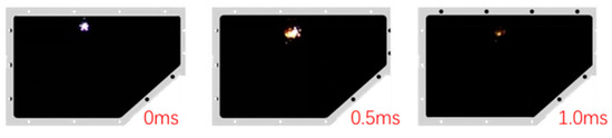
Figure 5.
Generation stage of the fire core during the ignition process of the igniter.
Figure 6 shows the images captured by a high-speed camera during the flame propagation stage. It can be seen that, in the initial stage of flame propagation, the fire core generated at the position of the electric spark propagates upstream under the action of the recirculation zone. Due to the limited area of the electric spark at this time, the impact on the flow field is also small; thus, the cold flow field velocity field becomes the main factor affecting the propagation of the fire core in this stage. As the fire core develops, its shape changes from a spherical shape at the beginning, to a long strip structure in the Z-axis direction, and then gradually propagates towards the negative Y-axis direction. At the same time, the average gray value of the flame also gradually increases with the propagation of the fire core. At 194 ms, the fire core splits into three flame fronts near the center of the model combustion chamber. The flame fronts formed here are closely related to the atomization characteristics of the nozzle and the flow field of the head swirl cup. On the one hand, it is located in the recirculation zone of the flow field, where the air flow velocity is low, which is conducive to the formation of flames. On the other hand, the oil mist film sprayed by the atomization nozzle breaks up here, forming droplets; thus, the fuel concentration here is high, which is conducive to the formation and stability of flames. After the flame is formed, it begins to spread upstream, and due to its certain intensity, it can resist the influence of negative velocity in the recirculation zone and begin to spread downstream, eventually filling the entire model combustion chamber. During this period, the average gray value of the flame also rapidly expands. From the above analysis, it can be seen that the flame front always travels in a direction conducive to the development of flames.
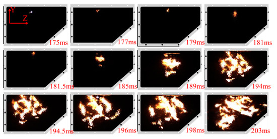
Figure 6.
Flame propagation process during the ignition of the igniter.
3.2. Influence of Combustion Chamber Air Flow and Residual Gas Coefficient on Ignition Process
3.2.1. Influence of Combustion Chamber Air Flow on Ignition Process
In order to obtain the influence law of different air flow rates on the formation of fire kernels and flame propagation during the ignition process of the microwave radiation igniter in the model combustion chamber, three different air flow rates were set up in the experiment, and comparative experiments were conducted under the same conditions without microwave-assisted ignition. In the experiment, the conditions were as follows: air flow rates Wa = 500 L/min, 600 L/min, and 700 L/min; aviation kerosene fuel supply Wf = 0.025 L/min, 0.029 L/min, and 0.035 L/min; residual gas coefficient α = 2; temperature of the oil–gas mixture T = 300 K; input voltage U = 27 V of the igniter drive power supply; the input current I = 3.5 A; pulse peak power P = 200 W of the microwave power supply; pulse frequency f = 10 kHz; and duty cycle d = 0.5. When the air flow rate is changed in the combustion chamber, images of the ignition process of the igniter are recorded using a high-speed camera with an image intensifier, with a frame rate of 2000 fps.
Figure 7 shows the image-enhanced contrast images of the ignition process of the igniter, before and after the application of microwaves, when the air flow rate Wa of the model combustion chamber is 500 L/min, the aviation kerosene supply Wf is 0.025 L/min, the residual gas coefficient α is 2, and the temperature of oil and gas T is 300 K. From the figure, it can be seen that, when the microwave power P is 0 W, the ignition process of the igniter basically conforms to the description of the ignition process in Section 3.1. After the formation of the fire core at the position of the electric spark, it is affected by the velocity field of the recirculation zone and propagates upstream, and then it gradually propagates towards the lower edge of the model combustion chamber, overcoming the negative velocity of the recirculation zone and propagating downstream towards the model combustion chamber. When the peak power P of the microwave pulse is 200 W and the pulse frequency f is 10 kHz, the ignition process of the igniter is slightly different. The fire core at the position of the electric spark generated by the igniter propagates upstream under the action of the recirculation zone. At the same time, the fire core overcomes the negative velocity of the recirculation zone and propagates downstream, and then gradually propagates towards the lower edge of the model combustion chamber. It can be seen that the enhancement effect of the microwave on flame propagation during ignition is mainly reflected in the development stage of the fire core. After microwave feeding, the propagation speed of the early flame is significantly accelerated, allowing the fire core to propagate upstream while overcoming the negative velocity of the recirculation zone and propagating downstream. Due to the promotion effect of the microwave on the early flame, the ignition delay time of the igniter is shortened after microwave application. By taking the moment when the average gray value of the flame image begins to increase as zero time, the ignition delay time of the igniter without microwave application is 25 ms, and the ignition delay time of the igniter with microwave application is 15 ms, with a relative reduction of 40%. From Figure 6, it can also be seen that, after microwave application, the brightness distribution of CH radicals in the flame is more uniform, and the combustion of aviation kerosene is more complete. Plasma is an important active substance in the ignition and combustion process, and the expansion of plasma clusters is a non-thermal mechanism. After the igniter discharges and breaks down to produce plasma, the plasma clusters absorb microwave energy, rapidly expand, and increase their distribution range, making the combustion of aviation kerosene more complete, which is consistent with the research results of the literature [5].
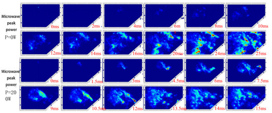
Figure 7.
Comparison of the ignition process before and after microwave-assisted ignition with an air flow rate of Wa = 500 L/min in the model combustion chamber.
By changing the air flow rate in the combustion chamber of the model, multiple ignition experiments were conducted under the same operating conditions. According to the definition of ignition delay time, the ignition delay time for each set of experiments was calculated, and the average ignition delay time under the same operating conditions was then calculated. The results are shown in Figure 8. As can be seen from the figure, as the air flow rate in the combustion chamber of the model increases, the relative decrease in ignition delay time gradually decreases. When the air flow rate Wa = 500 L/min, the ignition delay time decreases by 9.9 ms, with a relative decrease of 38%. When the air flow rate Wa = 700 L/min, the ignition delay time decreases by 9.5 ms, with a relative decrease of 27.5%. It can be concluded that, as the air flow rate increases, the air flow velocity in the combustion chamber of the model increases, and the promotion effect of the microwave on flame propagation decreases relatively. This indicates that a microwave with a relatively higher peak power is needed at this time, which will be verified in subsequent experiments.
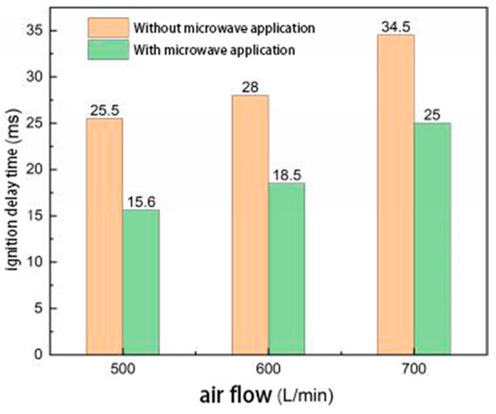
Figure 8.
Comparison of the ignition delay time before and after microwave-assisted ignition under different air flow rates.
To further investigate the impact of microwave-assisted ignition on flame kernel formation and flame propagation under different air flow rates, MATLAB was utilized to calculate the real-time flame area during the flame propagation process. The flame area values were normalized by determining the ratio of the target pixel points to the total pixel points in the image, and the results were plotted as a curve, as shown in Figure 9. It can be seen from the figure that, during the formation stage of the fire kernel, after microwave-assisted ignition was applied, the fire kernel formed first and was successfully ignited, indicating that the microwave feed allowed sufficient energy to accumulate near the igniter electrode in advance. As the air flow rate increases, the time of fire kernel formation gradually coincides with the time of the fire kernel formation without microwave-assisted ignition, at which point the microwave’s enhancement effect on the fire kernel cannot overcome the effects of turbulent mixing and turbulent diffusion in the recirculation zone, thus preventing it from forming a fire kernel first and successfully igniting. In the initial stage of flame propagation, the slope of the rising curve of the flame area value after microwave-assisted ignition is slightly larger than that of the flame area value without microwave-assisted ignition, indicating that the flame propagation speed after microwave-assisted ignition is higher than that without microwave-assisted ignition in the initial stage of flame propagation, which is consistent with the previous analysis. It can also be seen that the maximum value of the flame area after microwave-assisted ignition is smaller than that without microwave-assisted ignition, indicating that the combustion of aviation kerosene is more complete after microwave application, and the flame has fully burned before spreading to a distant location, which verifies the previous analysis.
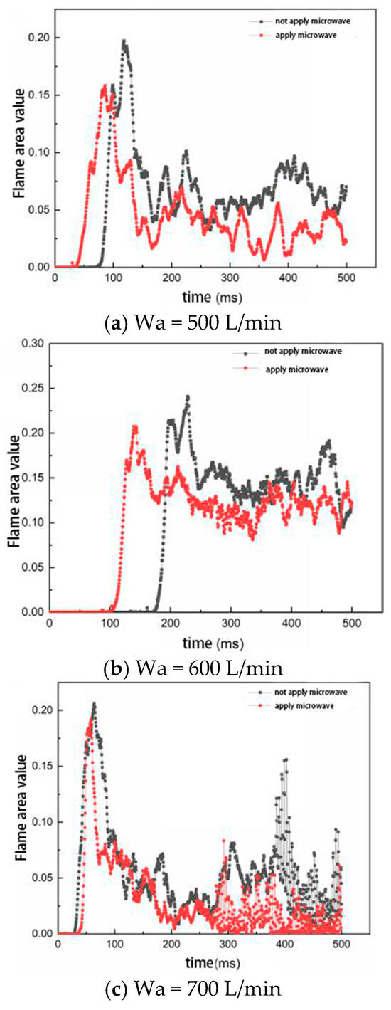
Figure 9.
Comparison of flame area values before and after microwave-assisted ignition under different air flow rates.
Based on the above analysis, it can be concluded that, during the ignition and flame propagation process of the model combustion chamber, the microwave feed is beneficial to the diffusion of plasma clusters generated by discharge breakdown, thus promoting the formation of the fire core and the propagation of the flame in the early stage, and making the combustion of aviation kerosene more complete. As the air flow rate in the model combustion chamber increases, the relative reduction in ignition delay time of the igniter gradually decreases, and the effect of the microwave gradually weakens, requiring microwave energy with higher pulse peak power.
3.2.2. The Influence of Residual Gas Coefficient on the Ignition Process
In order to obtain the influence of different residual gas coefficients on the formation of fire kernels and flame propagation during the ignition process of the microwave radiation igniter, three different residual gas coefficients were set up in the experiment, and comparative experiments were conducted under the same conditions without the application of microwaves. In the experiment, the following conditions were applied: residual gas coefficients α = 0.8, 1, and 2; air flow rate Wa = 600 L/min; aviation kerosene fuel supply Wf = 0.074 L/min, 0.059 L/min, and 0.029 L/min; temperature of the gas–oil mixture T = 300 K; input voltage U = 27 V of the igniter drive power supply; input current I = 3.5 A; pulse peak power P = 200 W of the microwave power supply; pulse frequency f = 10 kHz; and duty cycle d = 0.5. When changing the fuel supply to change the residual gas coefficient, the ignition process images were recorded using a high-speed camera with an image intensifier, with a frame rate of 2000 fps.
As shown in Figure 10, the ignition process of the igniter before and after the application of microwaves is compared using enhanced contrast images when the air flow rate in the model combustion chamber is Wa = 600 L/min, the aviation kerosene fuel supply Wf = 0.074 L/min, the residual gas coefficient α = 0.8, and the temperature of the oil–gas mixture T = 300 K. It can be seen from the figure that there is not much difference in the ignition process of the igniter before and after the application of microwaves. In the rich combustion state, when no microwaves are applied, the fire core is propagated upstream under the influence of the flow field in the recirculation zone, while the fire core can still overcome the negative velocity of the recirculation zone and propagate downstream, and then the flame develops towards the lower edge of the model combustion chamber. When microwaves are applied, the propagation of the fire core is not much different from that without microwaves, and due to the randomness of the experiment, the ignition delay time is 12 ms longer than that without microwaves. Unlike the case without microwaves, the combustion of aviation kerosene is more intense after microwaves are applied, and it can be seen that the brightness of the CH-based flame is greater after microwaves are applied, which is inseparable from the large amount of active particles contained in the plasma generated by microwave discharge breakdown.
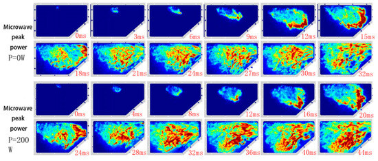
Figure 10.
Comparison of flame propagation before and after microwave-assisted ignition with a residual gas coefficient of α = 0.8.
Figure 11 shows the results of changing the supply of aviation kerosene to change the residual gas coefficient, conducting multiple ignition experiments under the same operating conditions, calculating the ignition delay time for each set of experiments based on the definition of ignition delay time, and then calculating the average ignition delay time under the same operating conditions. From Figure 11, it can be seen that, when the residual gas coefficient α = 0.8 under the rich combustion state, the ignition delay time before and after applying microwave-assisted ignition is approximately equal; when the residual gas coefficient α = 1 under the stoichiometric combustion state, the relative decrease in ignition delay time before and after applying microwave-assisted ignition is 16.5%; when the residual gas coefficient α = 2 under the lean combustion state, the relative decrease in ignition delay time before and after applying microwave-assisted ignition is 33.9%. It can be concluded that, as the residual gas coefficient increases, the relative decrease in ignition delay time of the igniter before and after applying microwave-assisted ignition gradually increases. When conducting ignition experiments under rich combustion conditions, the flame combustion is extremely intense, accompanied by strong sound and flame oscillation phenomena. Finally, a large amount of unburned hydrocarbon mixture black smoke is observed at the outlet of the combustion chamber. The analysis shows that, under rich combustion conditions, the combustion chemical reaction is more intense, the flame front velocity is faster, and the microwave energy cannot be effectively coupled to the front end of the flame front. Therefore, the effect of applying microwave-assisted ignition is not very obvious. Under the proper chemical ratio and lean combustion conditions, the combustion is more moderate, and there is no strong sound and flame oscillation phenomena. Therefore, after applying microwaves, more microwave energy is coupled to the front end of the flame front, which increases the flame propagation speed and promotes the flame propagation.
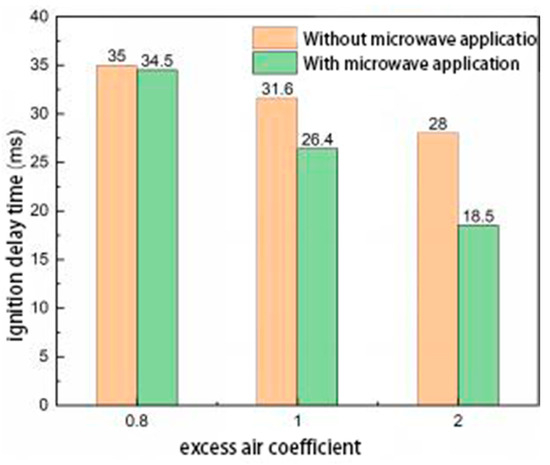
Figure 11.
Comparison of ignition delay time before and after microwave-assisted ignition under different residual gas coefficients.
In order to further investigate the influence of microwave-assisted ignition on the formation of the fire core and the flame propagation process under different residual gas coefficients, the real-time area of the flame during the flame propagation process under different residual gas coefficients was calculated and plotted as a curve, as shown in Figure 12. It can be seen from the figure that, in the stage of fire core formation, after microwave-assisted ignition is applied, the fire core is first formed and successfully ignited. In the initial stage of flame propagation, the slope of the rising curve of the flame area value under the rich fuel state after microwave application is almost the same as that before microwave application, indicating that the microwave feed-in did not achieve good results in the initial stage of flame propagation, which is consistent with the previous analysis. It can also be seen that the slope of the rising curve of the flame area value under the chemical appropriate ratio and lean fuel state after microwave application is slightly larger than that without microwave application, indicating that the flame propagation speed increases after microwave application, thus promoting the propagation of the flame under the chemical appropriate ratio and lean fuel state.
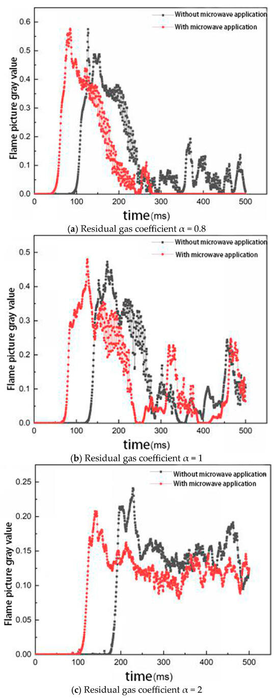
Figure 12.
Comparison of flame area values before and after microwave-assisted ignition under different residual gas coefficients.
Based on the above analysis, it can be concluded that, during the flame propagation process in the model combustion chamber, the microwave feed is beneficial to promoting the formation of a flame kernel and flame propagation under the conditions of the appropriate chemical ratio and lean combustion, but it has no significant effect on the flame propagation under the conditions of rich combustion. As the residual gas coefficient increases, the relative reduction in ignition delay time of the igniter gradually increases, and the effect of microwaves gradually increases.
3.3. The Influence of Microwave Pulse Parameters on the Ignition Process
3.3.1. The Influence of Microwave Pulse Frequency on the Ignition Process
In order to obtain the influence of different microwave pulse frequencies on the formation of fire kernels and flame propagation during the ignition process of microwave radiation ignitors, the experiment set up three different pulse frequencies based on the existing microwave power supply, which were 1 kHz, 5 kHz, and 10 kHz, with a pulse peak power of P = 200 W and a duty cycle of d = 0.5. In the experiment, the air flow rate Wa = 600 L/min, the aviation kerosene supply Wf = 0.029 L/min, the residual gas coefficient α = 2, the temperature of the gas-oil mixture T = 300 K, the input voltage U = 27 V of the igniter drive power supply, and the input current I = 3.5 A. When changing the microwave pulse frequency, the ignition process images were recorded using a high-speed camera with an image intensifier, with a frame rate of 2000 fps.
As shown in Figure 13, the ignition process of the igniter is enhanced and contrasted when the air flow rate in the model combustion chamber Wa = 600 L/min, the aviation kerosene fuel supply Wf = 0.029 L/min, the residual gas coefficient α = 2, the microwave pulse frequency is 1 kHz and 10 kHz, respectively, and the microwave pulse peak power P = 200 W. The temperature of the gas–oil mixture T = 300 K. From the figure, it can be seen that there is no significant difference in the flame propagation process when the microwave pulse frequency is 1 kHz and 10 kHz, respectively. When the microwave pulse frequency is 10 kHz, the brightness of the CH radical in the flame is higher and the ignition delay time is shorter, indicating that the increase in microwave pulse frequency makes the moment of discharge breakdown of the gas mixture by the igniter to produce plasma clusters more likely to coincide with the duration of microwave existence, which is beneficial for the plasma clusters to better absorb microwave energy, thus better promoting the formation of ignition fire core and flame propagation and shortening the ignition delay time.
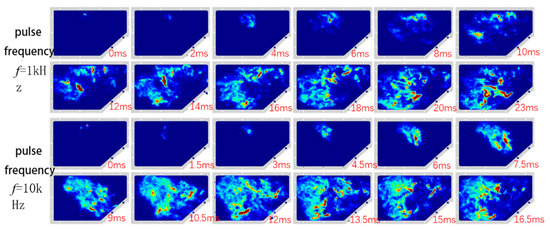
Figure 13.
Comparison of ignition process of igniters with microwave pulse frequency f = 1 kHz and 10 kHz.
By changing the microwave pulse frequency and conducting multiple ignition experiments under the same operating conditions, the ignition delay time for each set of experiments was calculated based on the definition of ignition delay time. The average ignition delay time for the same operating conditions was then calculated, and the results are shown in Figure 14.
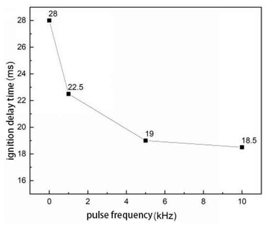
Figure 14.
Comparison of ignition delay time of igniters at different microwave pulse frequencies.
When the microwave pulse frequency f = 1 kHz, the ignition delay time is 22.5 ms, which is 5.5 ms lower than that without microwaves, and the relative reduction is 19.6%. Then, as the microwave pulse frequency increases, the decreasing trend of the ignition delay time tends to moderate. In Section 3.3, it is found that, as the microwave pulse frequency increases, the breakdown voltage of the igniter gradually decreases, because the discharge time of the igniter has a greater probability of coinciding with the duration of the microwave field. At the moment of igniter discharge breakdown, the number of electrons near the electrode rises sharply, and then, due to electron collisions, recombination, etc., the number of electrons near the electrode drops sharply. The duration of high electron density is short, but sufficient electron density is the key to plasma coupling microwave energy. Therefore, as the pulse frequency increases, although the discharge time of the igniter has a greater probability of coinciding with the duration of the microwave field, due to the existence of the duty cycle, when the frequency is too high, even if the discharge time can coincide with the duration of the microwave field, the time is short, making the plasma unable to fully couple microwave energy, and the promotion effect on the propagation of ignition fire core is weakened.
In order to further investigate the influence of microwave-assisted ignition on the formation of the fire core and the flame propagation process under different microwave pulse frequencies, the real-time area of the flame during the flame propagation process when the igniter is ignited under different microwave pulse frequencies was calculated, and the resulting curves are shown in Figure 15. It can be seen from the figure that, in the stage of fire core formation, as the microwave pulse frequency increases, the time of fire core formation becomes earlier and earlier, indicating that the increase in microwave pulse frequency is beneficial to the accumulation of sufficient energy near the igniter electrode to successfully ignite. In the initial stage of flame propagation, as the microwave pulse frequency increases, the slope of the rising curve of the flame area value gradually increases, indicating that the flame propagation speed becomes faster and faster, which is consistent with the previous analysis.
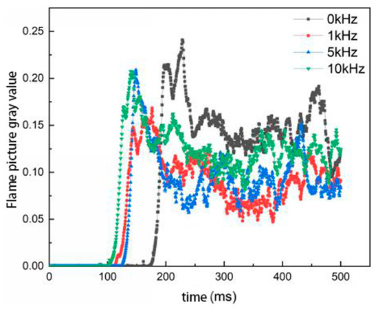
Figure 15.
Comparison of flame area values during ignition of the igniter at different microwave pulse frequencies.
Based on the above analysis, it can be concluded that, as the microwave pulse frequency increases, the brightness of the CH radical in the flame during the ignition process of the microwave radiation igniter increases, and the combustion of aviation kerosene becomes more complete. As the microwave pulse frequency increases, the formation time of the fire core becomes earlier, the flame propagation speed increases accordingly, and the ignition delay time is shortened accordingly.
3.3.2. Influence of Microwave Pulse Peak Power on the Ignition Process
In order to obtain the influence of different microwave pulse peak powers on the formation of fire kernels and flame propagation during the ignition process of the microwave radiation igniter, the experiment set up four different pulse peak powers based on the existing microwave power supply, which were 0 W, 100 W, 150 W, and 200 W, respectively. The pulse frequency f = 10 kHz and the duty cycle d = 0.5. In the experiment, the air flow rate Wa = 600 L/min, the aviation kerosene supply Wf = 0.029 L/min, the residual gas coefficient α = 2, the temperature of the gas–oil mixture T = 300 K, the input voltage U = 27 V of the igniter drive power supply, and the input current = 3.5 A. When changing the microwave pulse peak power, the image of the ignition process was recorded using a high-speed camera with an image intensifier, and the frame rate was 2000 fps.
As shown in Figure 16, the image-enhanced comparative images of the ignition process of the igniter when the model combustion chamber air flow rate Wa = 600 L/min, the aviation kerosene fuel supply Wf = 0.029 L/min, the residual gas coefficient α = 2, the microwave pulse peak power is 100 W and 200 W, respectively, the pulse frequency f = 10 kHz, and the oil and gas temperature T = 300 K. It can be seen from the figure that the brightness of the CH radical in the flame when the microwave pulse peak power is 200 W is higher than that when the pulse peak power is 100 W, and the ignition delay time is also shorter, indicating that the increase in microwave pulse peak power is beneficial to the plasma cluster generated by the igniter discharge breakdown, absorbing more microwave energy and better promoting the formation of the fire core and the propagation of the flame.
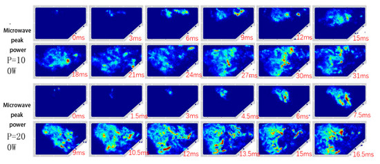
Figure 16.
Comparison of the ignition process of igniters with microwave pulse peak power P = 100 W and 200 W.
By changing the peak power of microwave pulses and conducting multiple ignition experiments under the same working condition, the ignition delay time for each set of experiments was calculated based on the definition of ignition delay time. The average ignition delay time under the same working condition was then calculated, and the results are shown in Figure 17. When the peak power of microwave pulses P = 100 W, the ignition delay time is not much different from that when the power is zero, only falling by 1.5 ms, indicating that the promotion effect of microwaves on the formation of fire core and flame propagation is not obvious when the power is 100 W. When the peak power of microwave pulses P = 150 W, the ignition delay time falls by 6 ms, which is a relatively large decrease, indicating that there is a critical peak power of microwave pulses that makes the effect of microwaves gradually increase after this value.
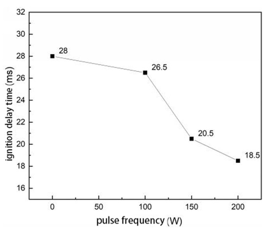
Figure 17.
Comparison of ignition delay time of igniters under different microwave pulse peak powers.
In order to further investigate the effect of microwave-assisted ignition on the formation of the fire kernel and the flame propagation process under different microwave pulse peak powers, the real-time area of the flame during the flame propagation process when the igniter is ignited under different pulse peak powers was calculated, and the resulting curves are shown in Figure 18. From Figure 18, it can be seen that, in the formation stage of the fire kernel, as the microwave pulse peak power increases, the formation time of the fire kernel becomes earlier and earlier, indicating that the plasma generated by the igniter discharge can absorb more microwave energy, thus accumulating sufficient energy near the igniter electrodes to achieve successful ignition. In the initial stage of flame propagation, as the microwave pulse peak power increases, the slope of the rising curve of the flame area value gradually increases, and the flame propagation speed becomes larger and larger, resulting in a gradual decrease in ignition delay time, which verifies the above analysis.
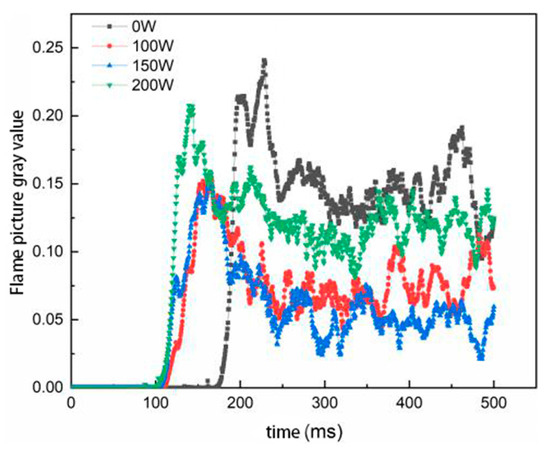
Figure 18.
Comparison of flame area values during ignition of the igniter under different microwave pulse peak powers.
Based on the above analysis, it can be concluded that, as the peak power of microwave pulses increases, the brightness of the CH radical in the flame during the ignition process of the microwave radiation igniter increases, which is beneficial to the formation of the fire core and the propagation of the flame, resulting in a more complete combustion of the aviation kerosene. As the peak power of the microwave pulses increases, the flame propagation speed also increases, and the ignition delay time is correspondingly shortened.
4. Conclusions
This study comprehensively examined the influencing factors on the operational characteristics of microwave radiation igniters and conducted an integrated quantitative analysis. Compared to previous research, it incorporated a broader range of variable impacts and employed innovative methodologies, such as high-speed photography and image-intensified flame self-luminescence imaging techniques. These advancements enabled a more systematic exploration of ignition mechanisms under complex conditions, further bridging critical gaps in this field. The findings not only deepen the understanding of microwave-assisted ignition dynamics but also provide a theoretical and experimental foundation for optimizing ignition systems in extreme aerospace environments.
The microwave radiation igniter was tested in a model combustion chamber to evaluate the effects of microwave pulse frequency, peak power, airflow rate, and residual gas coefficient (α) on ignition delay and flame development. The results indicated that microwave application systematically enhanced ignition efficiency across varying operational parameters.
The ignition process comprised flame kernel formation, propagation, and stabilization stages. Microwave energy promoted rapid kernel generation and accelerated flame propagation by counteracting reverse flow velocities, thereby reducing ignition delay. This acceleration was attributed to microwave–plasma interactions during early flame growth.
Increased airflow rate diminished the microwave-induced reduction in ignition delay, with kernel formation time converging toward non-microwave conditions at high flows. Residual gas coefficient variations revealed distinct impacts; under fuel-rich (α = 0.8), stoichiometric (α = 1), and lean-fuel (α = 2) conditions, the relative delay reductions were negligible, 16.5%, and 33.9%, respectively.
Microwave pulse frequency and peak power critically influence ignition dynamics. At 1 kHz frequency, delay decreased by 19.6% (22.5 ms vs. 28.0 ms), while higher frequencies gradually attenuated this effect. Elevated peak power strengthens plasma–microwave coupling, enhancing flame propagation and further shortening delay times.
Author Contributions
Conceptualization, H.Z.; methodology, H.Z.; software, C.F.; validation, Z.Z. and C.F.; formal analysis, H.Z. and C.F.; investigation, Z.Z.; resources, H.Z.; data curation, C.F.; writing—original draft preparation, C.F.; writing—review and editing, H.Z.; visualization, C.F. and Z.Z.; supervision, H.Z.; project administration, H.Z.; funding acquisition, H.Z. All authors have read and agreed to the published version of the manuscript.
Funding
The Project Supported by Natural Science Basic Research Plan in Shaanxi Province of China, grant number [Program No.2020JM-349].
Data Availability Statement
Data are contained within the article.
Conflicts of Interest
The authors declare no conflict of interest.
Nomenclature
| Wa | Combustion chamber air flow rate |
| Wf | Jet fuel supply flow rate |
| α | Excess air coefficient |
| T | Mixture temperature |
| P | Microwave pulse peak power |
| f | Microwave pulse frequency |
References
- Ikeda, Y.; Nishiyama, A.; Kaneko, M. Microwave Enhanced Ignition Process for Fuel Mixture at Elevated Pressure of 1 Mpa. In Proceedings of the AIAA Aerospace Sciences Meeting Including the New Horizons Forum & Aerospace Exposition, Orlando, FL, USA, 5–8 January 2009. [Google Scholar]
- Wolk, B. Stability Limit Extension of a Wet Ethanol-fueled SI Engine using a Microwave-assisted Spark. Adv. Automob. Eng. 2015, 4, 1. [Google Scholar] [CrossRef]
- Wolk, B.; Defilippo, A.; Chen, J.; Dibble, R.; Nishiyama, A.; Ikeda, Y. Enhancement of flame development by microwave-assisted spark ignition in constant volume combustion chamber. Combust. Flame 2013, 160, 1225–1234. [Google Scholar] [CrossRef]
- Hwang, J.; Bae, C.; Park, J.; Choe, W.; Cha, J.; Woo, S. Microwave-assisted plasma ignition in a constant volume combustion chamber. Combust. Flame 2016, 167, 86–96. [Google Scholar] [CrossRef]
- Padala, S.; Nishiyama, A.; Ikeda, Y. Flame size measurements of premixed propane-air mixtures ignited by microwave-enhanced plasma. Proc. Combust. Inst. 2016, 36, 4113–4119. [Google Scholar] [CrossRef]
- Zhang, X.; Wang, Z.; Zhou, D.; Wu, H.; Cheng, X.; Jin, B.; Chen, J.Y. Strengthening effect of microwave on spark ignited spherical expanding flames of methane-air mixture. Energy Convers. Manag. 2020, 224, 113368. [Google Scholar] [CrossRef]
- Zhang, X.; Wang, Z.; Wu, H.; Zhou, D.; Huang, S.; Cheng, X.; Chen, J.Y. Combustion and Flame Experimental study of microwave assisted spark ignition on expanding C2H2-Air spherical flames. Combust. Flame 2020, 222, 111–122. [Google Scholar] [CrossRef]
- Zhang, X.; Wang, Z.; Huang, S.; Wu, H.; Jin, B.; Cheng, X. Effect of microwave-assisted ignition on premixed spherical flame of methane. J. Intern. Combust. Engines 2020, 38, 38–45. [Google Scholar]
- Wang, Z. Research on Methanol Ignition Characteristics Based on Microwave-Assisted Ignition; Huazhong University of Science and Technology: Wuhan, China, 2022. [Google Scholar] [CrossRef]
- Liu, C. Research on Microwave-Assisted Ammonia/Hydrogen Fuel Ignition Based on Microwave Energy Flow; Huazhong University of Science and Technology: Wuhan, China, 2023. [Google Scholar] [CrossRef]
- Jiang, R.P.; Liu, G.Z.; Zhang, X.W. Thermal Cracking of Hydrocarbon Aviation Fuels in Regenerative Cooling Microchannels. Energy Fuels 2013, 27, 2563–2577. [Google Scholar] [CrossRef]
- Lacaze, G.; Cuenot, B.; Poinsot, T.; Oschwald, M. Large Eddy Simulation of laser ignition and compressible reacting flow in a rocket-like configuration. Combust. Flame 2009, 156, 1166–1180. [Google Scholar] [CrossRef]
Disclaimer/Publisher’s Note: The statements, opinions and data contained in all publications are solely those of the individual author(s) and contributor(s) and not of MDPI and/or the editor(s). MDPI and/or the editor(s) disclaim responsibility for any injury to people or property resulting from any ideas, methods, instructions or products referred to in the content. |
© 2025 by the authors. Licensee MDPI, Basel, Switzerland. This article is an open access article distributed under the terms and conditions of the Creative Commons Attribution (CC BY) license (https://creativecommons.org/licenses/by/4.0/).