Article

An Analytical Study on the Thermal Post-Buckling Behaviors of Geometrically Imperfect FRC-Laminated Beams Using a Modified Zig-Zag Beam Model

School of Aeronautics Science and Engineering, Beihang University, Beijing 100191, China
*
Author to whom correspondence should be addressed.
Aerospace 2025, 12(2), 138; https://doi.org/10.3390/aerospace12020138
Submission received: 3 December 2024 / Revised: 16 January 2025 / Accepted: 21 January 2025 / Published: 12 February 2025
(This article belongs to the Section Aeronautics)

Abstract

:
An asymptotic analytical method is proposed to study the thermal post-buckling behaviors of fiber-reinforced composite (FRC)-laminated beams with geometric imperfections employing a modified zig-zag beam model. The beam model satisfied the discontinuity of the shear deformation at the interlayer interfaces and the stress boundary conditions on the upper and lower surfaces. Each imperfection was assumed to possess the same shape as the buckling mode, and the in-plane boundary conditions were presumed to be immovable. A two-step perturbation method was used to solve the nonlinear governing equations and obtain the equilibrium path. Subsequently, the initial defect sensitivity of the post-buckling behaviors was analyzed. The existence of the bifurcation-type equilibrium path for perfect beams is discussed in depth. Load–deflection curves for beams with various boundary conditions and ply modes were plotted to illustrate these findings. The effects of the slenderness ratio, elastic modulus ratio, thermal expansion coefficient ratio, ply modes, and supported boundaries on the buckling and post-buckling behaviors were also investigated. The numerical results indicate that the slenderness ratio significantly influences the critical buckling temperature, with thicker beams exhibiting higher buckling resistance. The elastic modulus ratio also plays a crucial role, with higher ratios leading to increased buckling strength. Additionally, the thermal expansion coefficient ratio affects the post-buckling load-bearing capacity, with lower ratios resulting in greater stability.

1. Introduction

As a kind of lightweight and high-strength material, fiber-reinforced composites (FRCs) are increasingly used in military aircrafts where weight and performance requirements are stringent [1,2,3,4,5,6,7,8,9,10,11,12,13,14,15,16,17,18,19,20,21,22,23]. However, the extreme service environment of military aircrafts imposes higher requirements for structural safety analysis and design techniques. These include the ability to predict the nonlinear response of structures under given working conditions, evaluate the influence of various factors on the response, and provide reliable estimates of the accuracy of the predictions [4,5]. For slender composite structures with immovable boundaries serving in aerospace, both the initial geometric imperfections and the axial compressive internal forces caused by the thermal environment can reduce axial stiffness and lead to structural buckling instability, which requires quantitative and precise analysis. Nowadays, research not only focuses on preventing buckling but also on maximizing the post-buckling load-bearing capacity of structures to meet lightweight design requirements [6,7]. To achieve this, accurate prediction of buckling behavior and detailed analysis of the stability and defect sensitivity of the post-buckling equilibrium path are critical.
Research on the post-buckling behaviors of geometrically imperfect beams has received a good amount of attention in the literature [8,9,10,11,12], revealing the important influence of geometric imperfections, support conditions, and other factors on structural buckling and post-buckling. Pawel Wysmulski and Hubert Debsk investigated the effect of the load eccentricity on the behavior of compressed composite columns in a critical state. An L1-mode imperfection refers to the first buckling mode shape of a beam, which is often considered the most critical mode in buckling analysis, especially in studies of geometrically imperfect beams, where it is commonly assumed to have the same shape as the first buckling mode due to its dominant influence on the beam’s stability. Based on Reddy’s higher-order shear deformation beam theory, the post-buckling behaviors of simply supported laminated beams with geometric imperfections were analyzed considering the temperature-dependent material properties and uniform temperature distribution through the thickness [8,13]. Yaghoobi and Torabi conducted post-buckling and nonlinear free vibration analyses of geometrically imperfect, functionally graded beams resting on a nonlinear elastic foundation using Galerkin’s method and the variational iteration method [14]. Wu et al. studied the sensitivity of the post-buckling behaviors of functionally graded carbon nanotube-reinforced composite beams to different types of initial generic geometric imperfections by the differential quadrature method and an iteration procedure [9]. The numerical results suggested that the post-buckling response is highly sensitive to the imperfection amplitude, especially for an L1-mode imperfection. Mohammadi et al. investigated the effects of nonlocal parameters, geometrical imperfections, and an elastic foundation on the static instability of a nonlinear nanobeam in post-buckling, snap-through, and bifurcation instability based on a size-dependent Euler–Bernoulli beam [15]. Fan and Wang studied the effects of the initial thermal bending moment, geometric imperfections, and matrix cracking on the thermal post-buckling behaviors of a beam with carbon nanotube-reinforced composite layers and piezoelectric fiber-reinforced composite layers based on a higher-order beam theory [16].
The accuracy of structural analysis results critically depends on the theoretical framework’s precision, which has driven considerable research efforts in developing nonlinear theories for beams, plates, and shells [17,18,19,20]. For decades, beam models like the Euler–Bernoulli beam, Timoshenko beam, and higher-order shear deformation beam have been well developed and successfully used for research on the static and dynamic characteristics of single-layer homogeneous isotropic beams. However, some limitations in accuracy will exist if these theories are applied to the analysis of laminated structures because these theories do not accurately describe the true displacement distribution of laminated structures, which should be continuous in the thickness direction due to differences in the stiffness of adjacent laminates. In the current terminology, the slope change at the interlayer interface is termed the zig-zag effect. The zig-zag effect describes the discontinuous distribution of shear strains at the interfaces between layers in laminated composite structures, where the displacement field through the thickness of a beam exhibits a “zig-zag” pattern due to differences in material properties between adjacent layers, an effect particularly important in thick laminated beams or those with significant differences in in-plane Young’s moduli. For laminated structures with large thicknesses or transverse shear deformation, research has suggested that the free vibration frequencies of structures obtained by the equivalent single-layer theory neglecting the zig-zag effect are quite different from those obtained by the three-dimensional elastic theory [21]. To address this limitation, layer-wise theories were developed, employing separate displacement variables per layer, enabling precise tracking of layer-specific variations [22]. However, the improvement of accuracy is at the expense of the large number of unknowns proportional to the number of layers. For composite laminated structures with more layers, too many displacement variables lead to the form of solutions being too complex, and the corresponding finite element model also lacks practical value because of the large number of nodal DOFs. To refine this method without increasing calculation costs, the equivalent single-layer zig-zag models have been developed to achieve the accuracy of layer-wise models with a lower number of variables. By adding a zig-zag function to the displacement field of the equivalent single-layer models, Murakami pioneered the development of zig-zag theories in which the continuity condition of displacement could be satisfied and the number of displacement variables could be independent of the number of layers [23]. Carrera modified the zig-zag function to meet the condition that the shear stress component on the upper and lower surfaces of the laminated beam is zero [24]. The numerical results revealed that the multilayered plate and shell theories can be greatly improved by the use of this modified zig-zag function. Based on this work, Xie et al. developed a general higher-order shear deformation zig-zag theory for analyzing the aero-thermoelastic characteristics of composite laminated panels under supersonic airflows [25]. Inspired by Qu and Carrera E’s work, this study applies the modified higher-order shear deformation zig-zag beam model to the post-buckling analysis of geometrically imperfect FRC laminated beams for the first time and analyzes the accuracy and applicability of the theory considering the zig-zag effect and not considering the zig-zag effect.
Numerous analytical and numerical approaches have been established for investigating static and dynamic behaviors of laminated beams, including but not limited to the variational method [26], Navier type method [27], Galerkin method [28], multiple scales methods [29], Green function method [30], harmonic balance method [31], differential quadrature method [9], finite element method [32], meshless method [33], and perturbation method [34]. For structures modeled by such a refined theory, considering the zig-zag effects at the interlayer interface, the finite element method is the general method for obtaining numerical solutions [35,36]. While previous studies have extensively investigated the post-buckling behavior of laminated beams using various beam theories, there is a lack of research on the thermal post-buckling behavior of geometrically imperfect beams using a modified zig-zag beam model. Moreover, current studies predominantly focus on hinged–hinged boundary conditions, neglecting other critical constraint configurations.
This study aims to fill this gap by proposing a refined model that accounts for the zig-zag effect and provides more accurate predictions of the post-buckling response. For the first time, a two-step perturbation method that has better computation efficiency and is more convenient for parameter analysis is used to obtain the asymptotic analytic solution to the post-buckling behaviors of slender structures modeled by a refined zig-zag theory where the displacement field is represented by a piecewise function. In this work, the buckling and post-buckling behaviors of perfect/imperfect hinged–hinged and clamped–clamped FRC laminated beams are systematically studied for the first time. The solution results based on the zig-zag theory and the equivalent single-layer theories are verified and compared in detail, and the applicability of the two kinds of theories are analyzed. Through detailed parameter study, various factors affecting the buckling and post-buckling behaviors of the beam are intuitively presented, and the existence of the equilibrium path of the bifurcation type is discussed in detail. It is believed that the current zig-zag models and the used solution methods can be extended to the study of the nonlinear static and dynamic characteristics of laminated or sandwich structures with more precise results.

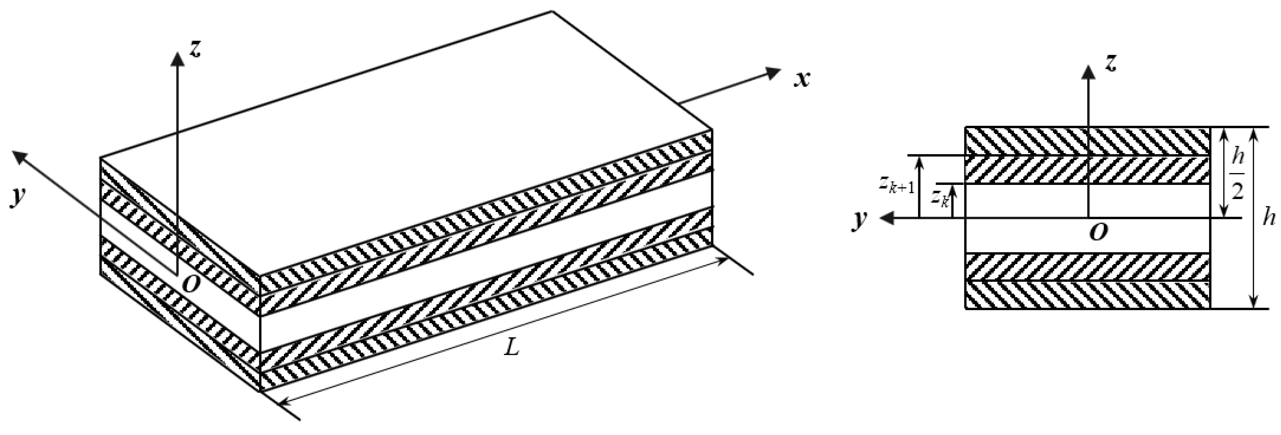
2. Modeling of FRC Laminated Beams

Consider a laminated composite beam with length L, thickness h, and unit width, consisting of N plies of any kind as shown in Figure 1. The two ends are assumed to be hinged–hinged or clamped–clamped and the in-plane boundary conditions considered immovable. Considering the large transverse shear deformation of the beam and the discontinuity of shear strain at interlayer interface, a zig-zag beam model based on Reddy’s higher-order shear deformation theory is adopted. The zig-zag effect describes the discontinuous distribution of shear strains at the interfaces between layers in laminated composite structures, where the displacement field through the thickness of the beam exhibits a “zig-zag” pattern due to differences in material properties between adjacent layers, an effect particularly important in thick laminated beams or those with significant differences in in-plane Young’s moduli. The axial and transverse displacement fields are expressed as
u ˜ x , z = u x + f z w x x + g z ϑ x + φ z , k η x
w ˜ x , z = w x + w x
where u ˜ and w ˜ are the displacements in x- and z-directions, respectively, at any material point in the (x, z) plane. u , w represent the axial and transverse displacements of the mid-plane in geometry, with the transverse initial geometric imperfection denoted by w . z is the depth of the material point measured from the mid-plane along the positive z-axis. w x is the rotation angle of the mid-plane, ϑ is the angle between the tangent of the warped section at the mid-plane and the positive z-axis, and η is a higher-order generalized displacement. f , g are the higher-order shape functions, defined as [17]
f ( z ) = 4 z 3 3 h 2 ,   g ( z ) = z 4 z 3 3 h 2
and φ is a zig-zag function that has been modified on the basis of Murakami’s zig-zag function to meet the stress boundary conditions [25]; that is
φ = 1 k 2 h k z 1 2 z k + 1 + z k 8 z 3 3 h k h 2
in which z k and z k + 1 represent the coordinates of the bottom and top of the kth laminate in the z-direction, while h k and h represent the thickness of the kth laminate and the whole beam, respectively.
According to Marguerre’s nonlinear theory of structures with initial deflection [36], the geometric equations considering the initial imperfection can be derived as
ε x x = u ˜ x + 1 2 w x 2 + w x w x = ε x x 0 + f ε x x 1 + g ε x x 2 + φ ε x x 3
γ z x = u ˜ z + w x = f ¯ γ z x ( 0 ) + g ¯ γ z x ( 1 ) + φ ¯ γ z x ( 2 )
in which ε x x ( i ) (i = 0, 1, 2, 3) are generalized in-plane positive strains; γ z x ( i ) (i = 0, 1, 2) are generalized shear strains; and f ¯ , g ¯ , and φ ¯ are defined as
f ¯ = f z + 1 ,   g ¯ = g z ,   φ ¯ = φ z
The generalized strain components defined in Equation (4) can be expressed as
ε x x ( 0 ) = u x + 1 2 w x 2 + w x w x x ,   ε x x ( 1 ) = 2 w x 2 ,   ε x x ( 2 ) = ϑ x ,   ε x x ( 3 ) = η x
γ z x ( 0 ) = w x ,   γ z x ( 1 ) = ϑ ,   γ z x ( 2 ) = η
Based on the in-plane bending assumption, stresses in the y-direction can be ignored, and the constitutive model of the kth layer of the beam in a thermal environment can be written as [37]
σ x x 0 0 ( k ) = Q ¯ 11 ( k ) Q ¯ 12 ( k ) Q ¯ 16 ( k ) Q ¯ 12 ( k ) Q ¯ 22 ( k ) Q ¯ 26 ( k ) Q ¯ 16 ( k ) Q ¯ 26 ( k ) Q ¯ 66 ( k ) ε x x ε y y ε x y ( k ) Δ T α x x α y y α x y ( k )
0 σ z x ( k ) = Q ¯ 44 ( k ) Q ¯ 45 ( k ) Q ¯ 45 ( k ) Q ¯ 55 ( k ) ε y z ε z x ( k )
The transformed thermal coefficients α x x , α y y , and α x y in Equation (8a) are defined as
α x x α y y α x y = m 2 n 2 n 2 m 2 2 m n 2 m n α 1 α 2
and Q ¯ i j ( k ) are the transformed stiffness coefficients, defined as [38]
Q ¯ 11 Q ¯ 22 Q ¯ 12 Q ¯ 66 Q ¯ 16 Q ¯ 26 k = m 4 n 4 2 m 2 n 2 4 m 2 n 2 n 4 m 4 2 m 2 n 2 4 m 2 n 2 m 2 n 2 m 2 n 2 m 4 + n 4 4 m 2 n 2 m 2 n 2 m 2 n 2 2 m 2 n 2 ( m 2 n 2 ) 2 m 3 n m n 3 m n 3 m 3 n 2 m n 3 m 3 n m n 3 m 3 n m 3 n m n 3 2 m 3 n m n 3 k Q 11 Q 22 Q 12 Q 66 k
Q ¯ 44 Q ¯ 45 Q ¯ 55 k = m 2 n 2 m n m n n 2 n 2 k Q 44 Q 55 k
in which
Q 11 k = E 1 k 1 μ 12 k μ 21 k , Q 12 k = μ 12 k E 2 k 1 μ 12 k μ 21 k , Q 22 k = E 2 k 1 μ 12 k μ 21 k
Q 66 k = G 12 , Q 44 k = G 23 , Q 55 k = G 13
and m = cos θ ,   n = sin θ , where θ is the lamination angle with respect to the beam axial direction.
On the basis of Equation (8), the axial normal stress and transverse shear stress at any point in the k-layer of the beam can be further written, according to the model in [39]
σ x x ( k ) = Q ˜ 11 k ε x x ( k ) Q ¯ 11 ( k ) Q ¯ 12 ( k ) Q ¯ 16 ( k ) α x x α y y α x y Δ T
τ z x ( k ) = Q ˜ 55 k γ z x ( k )
where
Q ˜ 11 k = Q ¯ 11 k Q ¯ 12 k Q ¯ 16 k T Q ¯ 22 k Q ¯ 26 k sym Q ¯ 66 k 1 Q ¯ 12 k Q ¯ 16 k
Q ˜ 55 k = Q ¯ 55 k 1 Q ¯ 44 k Q ¯ 45 k 2
By integrating stresses in the thickness direction, the generalized internal forces and moments are expressed as
N x M x P x T x = A 11 B 11 E 11 F 11 D 11 G 11 H 11 I 11 J 11 s y m R 11 ε x x 0 ε x x 1 ε x x 2 ε x x 3 A 11 T B 11 T E 11 T F 11 T Δ T
Q z x P z x T z x = D 55 G 55 H 55 I 55 J 55 s y m R 55 γ z x 0 γ z x 1 γ z x 2
where N x and Q z x are axial positive and transverse shear forces, M x is the bending moment per unit length, P x and T x are higher-order bending moments, and P z x and T z x are higher-order shear forces. The beam reduced stiffness coefficients are expressed by
A 11 , B 11 , D 11 , E 11 , F 11 , G 11 , H 11 , I 11 , J 11 , R 11 = k = 1 N l z k z k + 1 1 , f , f 2 , g , φ , f g , f φ , g 2 , g φ , φ 2 Q ˜ 11 k d z
( D 55 , G 55 , H 55 , I 55 , J 55 , R 55 ) = k = 1 N l z k z k + 1 f ¯ 2 , f ¯ g ¯ , f ¯ φ ¯ , g ¯ 2 , g ¯ φ ¯ , φ ¯ 2 Q ˜ 55 k d z
and
A 11 T , B 11 T , E 11 T , F 11 T = k = 1 N l z k z k + 1 1 , f , g , φ α ˜ x k d z
in which
α ˜ x k = Q ¯ 11 k Q ¯ 12 k Q ¯ 16 k α x α y α x y
The virtual work performed by the external force is ignored, and the Hamilton energy-variational principle for such a beam is
t 1 t 2 δ T δ U d t = 0
where δ U is the virtual strain energy, δ T is the virtual kinetic energy, and
U = 1 2 k = 1 N l z k z k + 1 0 L σ x x k ε x x k + τ x z k γ x z k d x d z = 1 2 0 L N x ε x x 0 + M x ε x x 1 + P x ε x x 2 + T x ε x x 3 + Q x z γ x z 0 + P x z γ x z 1 + T x z γ x z 2 d x
T = 1 2 k = 1 N l z k z k + 1 0 L ρ k u ˙ + f w ˙ x + g ϑ ˙ + φ η ˙ 2 + w ˙ 2 d x d z
Through variational operations, the following equations of motion can be obtained
δ u : N x x = ρ 0 u ¨ + ρ 1 w ¨ x + ρ 2 ϑ ¨ + ρ 3 η ¨
δ w : Q x z x 2 M x x 2 + N x 2 w + w x 2 = ρ 0 w ¨ x ρ 1 u ¨ + ρ 4 w ¨ x + ρ 5 ϑ ¨ + ρ 6 η ¨
δ ϑ : P x x P x z = ρ 2 u ¨ + ρ 5 w ¨ x + ρ 7 ϑ ¨ + ρ 8 η ¨
δ η : T x x T x z = ρ 3 u ¨ + ρ 6 w ¨ x + ρ 8 ϑ ¨ + ρ 9 η ¨
where
ρ 0 , ρ 4 , ρ 5 , ρ 6 , ρ 7 , ρ 8 , ρ 9 = k = 1 N l z k z k + 1 ρ k 1 , f 2 , f g , f φ , g 2 , g φ , φ 2 d z

3. Approximate Analytical Solutions of Post-Buckling Response

Because the thermal expansion of structure is regarded as a quasi-static process, the equilibrium equations governing the static response of the beam can be obtained from Equation (21) by eliminating the time-dependent terms, which are
δ u : N x x = 0
δ w : Q x z x 2 M x x 2 + N x 2 w + w x 2 = 0
δ ϑ : P x x P x z = 0
δ η : T x x T x z = 0
Substituting Equations (6), (7) and (14) into Equation (22) leads to the governing equations expressed by generalized displacements
x A 11 u x + 1 2 w x 2 + w x w x + B 11 2 w x 2 + E 11 ϑ x + F 11 η x A 11 T Δ T = 0
x D 55 w x + G 55 ϑ + H 55 η + N x 2 w + w x 2 2 x 2 D 11 2 w x 2 + G 11 ϑ x + H 11 η x B 11 2 x 2 u x + 1 2 w x 2 + w x w x = 0
x G 11 2 w x 2 + I 11 ϑ x + J 11 η x + E 11 u x + 1 2 w x 2 + w x w x G 55 w x + I 55 ϑ + J 55 η = 0
x H 11 2 w x 2 + J 11 ϑ x + R 11 η x + F 11 u x + 1 2 w x 2 + w x w x H 55 w x + J 55 ϑ + R 55 η = 0
One notes that Equation (23a) may be solved for the axial displacement u, and hence it can be eliminated from the other three equations. By integrating Equation (23) with respect to the spatial coordinate x yields, we can obtain
A 11 u x + 1 2 w x 2 + w x w x + B 11 2 w x 2 + E 11 ϑ x + F 11 η x = C 1 = N x + A 11 T Δ T
In Equation (24), C 1 is a constant of integration. Integrate Equation (24) once more, and one has
u L 0 = 0 L 1 2 w x 2 + w x w x d x B 11 A 11 w x L 0 E 11 A 11 ϑ L 0 F 11 A 11 η L 0 + C 1 A 11 x L 0
and
N x + A 11 T Δ T L = 0 L A 11 u x + 1 2 w x 2 + w x w x + B 11 2 w x 2 + E 11 ϑ x + F 11 η x d x
For a FRC beam with immovable ends, the boundary conditions for central axial displacement can be expressed as u 0 = u L = 0 , and thus Equation (25) can be further written
C 1 = 1 L 0 L A 11 1 2 w x 2 + w x w x d x + B 11 w x L 0 + E 11 ϑ L 0 + F 11 η L 0
N x = 1 L 0 L A 11 1 2 w x 2 + w x w x + B 11 2 w x 2 + E 11 ϑ x + F 11 η x d x A 11 T Δ T
By substituting Equation (26a) back into Equation (24), we can obtain
A 11 u x + 1 2 w x 2 + w x w x = 1 L 0 L A 11 1 2 w x 2 + w x w x d x + B 11 w x L 0 + E 11 ϑ L 0 + F 11 η L 0 B 11 2 w x 2 + E 11 ϑ x + F 11 η x
For a FRC beam with immovable fixed–fixed ends, the boundary conditions can be expressed as
u 0 = u L = w x 0 = w x L = η 0 = η L = ϑ 0 = ϑ L = 0
and thus Equation (26) can be further simplified as
C 1 = A 11 L 0 L 1 2 w x 2 + w x w x d x
N x = A 11 L 0 L 1 2 w x 2 + w x w x d x A 11 T Δ T
Substitute Equation (29a) back into Equation (24), and we can obtain
A 11 u x + 1 2 w x 2 + w x w x = A 11 L 0 L 1 2 w x 2 + w x w x d x B 11 2 w x 2 + E 11 ϑ x + F 11 η x
From the above analysis, it can be seen that the axial force N x of a beam with two immovable ends can be expressed as
N x = A 11 L 0 L 1 2 w x 2 + w x w x d x A 11 T Δ T           for   clamped - clamped   ends 1 L 0 L A 11 1 2 w x 2 + w x w x + B 11 2 w x 2 + E 11 ϑ x + F 11 η x d x A 11 T Δ T       for   hinged - hinged   ends or   hinged - clamped   ends
Equations (29) and (30) are still true when the laminated beam is symmetrically layered even if the boundary conditions at both ends are not clamped–clamped.

3.1. Clamped–Clamped Support

By substituting Equations (29b) and (30) into Equation (23b–d), the simplified governing equations for clamped–clamped ends can be obtained
D 11 B 11 2 A 11 4 w x 4 + G 11 B 11 E 11 A 11 3 ϑ x 3 + H 11 B 11 F 11 A 11 3 η x 3 A 11 2 L 0 L w x 2 + 2 w x w * x d x A 11 T Δ T 2 w + w * x 2 D 55 2 w x 2 G 55 ϑ x H 55 η x = 0
G 11 B 11 E 11 A 11 3 w x 3 + I 11 E 11 2 A 11 2 ϑ x 2 + J 11 E 11 F 11 A 11 2 η x 2 G 55 w x + I 55 ϑ + J 55 η = 0
H 11 B 11 F 11 A 11 3 w x 3 + J 11 E 11 F 11 A 11 2 ϑ x 2 + R 11 F 11 2 A 11 2 η x 2 H 55 w x + J 55 ϑ + R 55 η = 0
To facilitate the mathematical treatment of the governing equations, the following dimensionless parameters are defined
X = π x L , W = w L , Θ = ϑ π , H = η π , λ T = Δ T , γ T = A 11 T L 2 π 2 D 0 , γ 0 = A 11 L 2 π 2 D 0 , W * = w * L γ 1 , γ 2 , γ 3 , γ 4 , γ 5 , γ 6 , γ 7 , γ 8 , γ 9 = 1 D 0 s 1 , s 2 , s 3 , s 4 , s 5 , s 6 , s 7 , s 8 , s 9 γ 10 , γ 11 , γ 12 , γ 13 , γ 14 , γ 15 = L 2 π 2 D 0 D 55 , G 55 , H 55 , I 55 , J 55 , R 55
in which
s 1 = D 11 B 11 2 A 11 , s 2 = G 11 B 11 E 11 A 11 , s 3 = H 11 B 11 F 11 A 11 s 4 = G 11 B 11 E 11 A 11 , s 5 = I 11 E 11 2 A 11 , s 6 = J 11 E 11 F 11 A 11 , s 7 = H 11 B 11 F 11 A 11 , s 8 = J 11 E 11 F 11 A 11 , s 9 = R 11 F 11 2 A 11 , D 0 = k = 1 N l z k z k + 1   Q ˜ 11 k z 2 d z
Substitute Equation (33) into Equation (32) and neglect the higher-order small terms, and the following dimensionless equations are obtained
γ 1 4 W X 4 + γ 2 3 Θ X 3 + γ 3 3 H X 3 π γ 0 2 0 π W X 2 d X γ T λ T 2 W + W * X 2 2 W X 2 π γ 0 0 π W X W * X d X γ 10 2 W X 2 γ 11 Θ X γ 12 H X = 0
γ 4 3 W X 3 + γ 5 2 Θ X 2 + γ 6 2 H X 2 γ 11 W X + γ 13 Θ + γ 14 H = 0
γ 7 3 W X 3 + γ 8 2 Θ X 2 + γ 9 2 H X 2 γ 12 W X + γ 14 Θ + γ 15 H = 0
The dimensionless boundary conditions can be expressed as
W 0 = W π = W x 0 = W x π = H 0 = H π = Θ π = Θ π = 0
Although the initial defects of the beam are random, studies have shown that the influence of the waveform defect is the most prominent, so it is assumed that the initial defect of the beam has the same form as the classical solution of the small deflection [10]; that is
W * = ε A 10 * 1 c o s 2 m X = ε μ A 10 1 1 c o s 2 m X
where μ = A 10 * A 10 1 is the imperfection parameter. It is worth noting that in the post-buckling stage, the defect parameter is a variable rather than a constant.
A two-step perturbation method is employed to solve Equations (35) and (36) and determine the thermal post-buckling equilibrium paths [40]. The two-step perturbation method is an analytical approach that solves nonlinear problems by first linearizing the governing equations with a small perturbation parameter and then refining the solution by considering higher-order terms, enabling precise analysis of complex systems. In the present case, thermal load and the generalized displacements are represented in the following series form,
λ T X , ε = k = 0 ε k λ T k X ,    W X , ε = k = 1 ε k w k X Θ X , ε = k = 1 ε k ϑ k X ,    H X , ε = k = 1 ε k η k X
where ε is a small perturbation parameter with no physical meaning, and k is the number of terms in series.
By substituting Equation (38) into Equation (35), a set of perturbation differential equations are derived. The first-order perturbation equations are expressed as O ε 1 :
γ 1 4 w 1 X 4 + γ 2 3 ϑ 1 X 3 + γ 3 3 η 1 X 3 + γ T λ T 0 2 X 2 w 1 + W * ε γ 11 ϑ 1 X γ 12 η 1 X γ 10 2 w 1 X 2 = 0
γ 4 3 w 1 X 3 + γ 5 2 ϑ 1 X 2 + γ 6 2 η 1 X 2 γ 11 w 1 X + γ 13 ϑ 1 + γ 14 η 1 = 0
γ 7 3 w 1 X 3 + γ 8 2 ϑ 1 X 2 + γ 9 2 η 1 X 2 γ 12 w 1 X + γ 14 ϑ 1 + γ 15 η 1 = 0
To solve the above partial differential equations, a set of displacement trial functions that satisfy the boundary conditions is introduced [41]
w 1 X = A 10 1 1 c o s 2 m X
ϑ 1 X = B 10 1 s i n 2 m X
η 1 X = C 10 1 s i n 2 m X
Substitute Equations (37) and (40) into Equation (39), and a set of linear equations can be obtained.
γ 10 γ T λ T 0 1 + μ + 2 m 2 γ 1 2 m 2 A 10 1 + γ 11 2 m + γ 2 2 m 3 B 10 1 + γ 12 2 m + γ 3 2 m 3 C 10 1 = 0
2 m 3 γ 4 + 2 m γ 11 A 10 1 + 2 m 2 γ 5 + γ 13 B 10 1 + 2 m 2 γ 6 + γ 14 C 10 1 = 0
2 m 3 γ 7 + 2 m γ 12 A 10 1 + 2 m 2 γ 8 + γ 14 B 10 1 + 2 m 2 γ 9 + γ 15 C 10 1 = 0
By solving Equation (41), the zero-order buckling temperature solutions can be obtained
λ T 0 = γ 11 + γ 2 2 m 2 B 10 1 A 10 1 + γ 12 + γ 3 2 m 2 C 10 1 A 10 1 2 m 1 + μ γ T + 2 m 2 γ 1 + γ 10 1 + μ γ T
in which
B 10 1 A 10 1 = 2 m 3 γ 4 + 2 m γ 11 2 m 2 γ 6 + γ 14 2 m 3 γ 7 + 2 m γ 12 2 m 2 γ 9 + γ 15 2 m 2 γ 5 + γ 13 2 m 2 γ 6 + γ 14 2 m 2 γ 8 + γ 14 2 m 2 γ 9 + γ 15
C 10 1 A 10 1 = 2 m 2 γ 5 + γ 13 2 m 3 γ 4 + 2 m γ 11 2 m 2 γ 8 + γ 14 2 m 3 γ 7 + 2 m γ 12 2 m 2 γ 5 + γ 13 2 m 2 γ 6 + γ 14 2 m 2 γ 8 + γ 14 2 m 2 γ 9 + γ 15
The second order equations can be written as O ε 2 :
γ 1 4 w 2 X 4 + γ 2 3 ϑ 2 X 3 + γ 3 3 η 2 X 3 γ 10 γ T λ T 0 2 w 2 X 2 γ 11 ϑ 2 X γ 12 η 2 X = γ T λ T 1 2 w 1 + W * / ε X 2
γ 4 3 w 2 X 3 + γ 5 2 ϑ 2 X 2 + γ 6 2 η 2 X 2 γ 11 w 2 X + γ 13 ϑ 2 + γ 14 η 2 = 0
γ 7 3 w 2 X 3 + γ 8 2 ϑ 2 X 2 + γ 9 2 η 2 X 2 γ 12 w 2 X + γ 14 ϑ 2 + γ 15 η 2 = 0
According to the form of equations, a set of trial functions of second-order generalized displacements satisfying boundary conditions is introduced again.
w 2 X = A 10 2 1 c o s 2 m X
ϑ 2 X = B 10 2 s i n 2 m X
η 2 X = C 10 2 s i n 2 m X
Substitute Equations (37) and (45) into Equation (44), and a set of linear second-order equations can be obtained.
γ 10 γ T λ T 0 + 2 m 2 γ 1 2 m 2 A 10 2 + γ 11 2 m + γ 2 2 m 3 B 10 2 + γ 12 2 m + γ 3 2 m 3 C 10 2 = γ T λ T 1 2 m 2 A 10 1
2 m 3 γ 4 + 2 m γ 11 A 10 2 + 2 m 2 γ 5 + γ 13 B 10 2 + 2 m 2 γ 6 + γ 14 C 10 2 = 0
2 m 3 γ 7 + 2 m γ 12 A 10 2 + 2 m 2 γ 8 + γ 14 B 10 2 + 2 m 2 γ 9 + γ 15 C 10 2 = 0
It can be proved that the unique solutions of Equation (46) are as follows
λ T 1 = 0
w 2 = ϑ 2 = η 2 = 0
The third-order equation can be written as O ε 3 :
γ 1 4 w 3 X 4 + γ 2 3 ϑ 3 X 3 + γ 3 3 η 3 X 3 γ 10 γ T λ T 0 2 w 3 X 2 γ 11 ϑ 3 X γ 12 η 3 X = π γ 0 2 0 π w 1 X 2 d X 2 w 1 + W * ε X 2 + 2 w 1 X 2 π γ 0 0 π w 1 X W * ε X d X γ T λ T 2 2 w 1 + W * ε X 2
γ 4 3 w 3 X 3 + γ 5 2 ϑ 3 X 2 + γ 6 2 η 3 X 2 γ 11 w 3 X + γ 13 ϑ 3 + γ 14 η 3 = 0
γ 7 3 w 3 X 3 + γ 8 2 ϑ 3 X 2 + γ 9 2 η 3 X 2 γ 12 w 3 X + γ 14 ϑ 3 + γ 15 η 3 = 0
According to the form of the equations, a set of trial functions of third-order generalized displacements satisfying boundary conditions is introduced again.
w 3 X = A 10 3 1 c o s 2 m X
ϑ 3 X = B 10 3 s i n 2 m X
η 3 X = C 10 3 s i n 2 m X
By substituting Equations (37) and (49) into Equation (48) and solving the obtained set of linear third-order equations in a similar way, the second-order buckling temperature solutions can be obtained
λ T 2 = γ 0 1 + 3 μ 2 m π A 10 1 2 4 γ T 1 + μ
and
w 3 X = ϑ 3 X = η 3 X = 0
Sufficient accuracy can be obtained by solving up to the third-order perturbation equations, according to [41]. The asymptotic solutions of the dimensionless deflection and thermal load can be written as the form of series expansion.
W X , ε = k = 1 ε k w k X = ε w 1 + O ε 4 = ε A 10 1 1 c o s 2 m X
λ T = λ T 0 + ε 2 λ T 2 + O ε 4 = γ 11 + γ 2 2 m 2 B 10 1 A 10 1 + γ 12 + γ 3 2 m 2 C 10 1 A 10 1 2 m 1 + μ γ T + 2 m 2 γ 1 + γ 10 1 + μ γ T + γ 0 1 + 3 μ 2 m π A 10 1 2 4 γ T 1 + μ
According to Equation (52a), we can obtain
W m = W | X = π 2 m = 2 ε A 10 1
Thus, the thermal post-buckling load–deflection relationships are obtained
λ T = λ T 0 + ε 2 λ T 2 + O ε 4 = γ 11 + γ 2 2 m 2 B 10 1 A 10 1 + γ 12 + γ 3 2 m 2 C 10 1 A 10 1 2 m 1 + μ γ T + 2 m 2 γ 1 + γ 10 1 + μ γ T + γ 0 1 + 3 μ m π W m 2 4 1 + μ γ T +
in which the expression of B 10 1 A 10 1 and C 10 1 A 10 1 is given by Equation (43).
It is remarkable that if there are no geometric defects in FRC laminated beams with clamped–clamped ends, the post-buckling thermal load–deflection curve of the bifurcation type can be obtained; that is
λ T = λ T 0 + ε 2 λ T 2 + O ε 4 = γ 11 + γ 2 2 m 2 B 10 1 A 10 1 + γ 12 + γ 3 2 m 2 C 10 1 A 10 1 2 m γ T + 2 m 2 γ 1 + γ 10 γ T + γ 0 m π W m 2 4 γ T +
Obviously, the equilibrium path of post-buckling is stable, and by letting W m = 0 , the critical buckling bifurcation points can be obtained
λ T c r = γ 11 + γ 2 2 m 2 B 10 1 A 10 1 + γ 12 + γ 3 2 m 2 C 10 1 A 10 1 2 m γ T + 2 m 2 γ 1 + γ 10 γ T
Note that in analytical formulas, m represents the order of buckling modes. By letting m = 1, the real post-buckling equilibrium path of clamped–clamped FRC laminated beams can be obtained.

3.2. Hinged–Hinged Support

By substituting Equations (26b) and (27) into Equation (23b–d) and neglecting the higher-order small terms, the simplified governing equations for FRC laminated beams with hinged–hinged ends can be obtained
D 11 B 11 2 A 11 4 w x 4 + G 11 B 11 E 11 A 11 3 ϑ x 3 + H 11 B 11 F 11 A 11 3 η x 3 D 55 2 w x 2 G 55 ϑ x H 55 η x 1 L 0 L A 11 1 2 w x 2 + w x w * x + B 11 2 w x 2 + E 11 ϑ x + F 11 η x d x A 11 T Δ T 2 w + w * x 2 = 0
G 11 B 11 E 11 A 11 3 w x 3 + I 11 E 11 2 A 11 2 ϑ x 2 + J 11 E 11 F 11 A 11 2 η x 2 G 55 w x + I 55 ϑ + J 55 η = 0
H 11 B 11 F 11 A 11 3 w x 3 + J 11 E 11 F 11 A 11 2 ϑ x 2 + R 11 F 11 2 A 11 2 η x 2 H 55 w x + J 55 ϑ + R 55 η = 0
On the basis of Equation (33), the following dimensionless parameters are further introduced.
ς 1 = B 11 L π 2 D 0 , ς 2 = E 11 L π 2 D 0 , ς 3 = F 11 L π 2 D 0
where the expression of D 0 is given by Equation (34).
Consequently, the dimensionless governing equations can be expressed as follows
γ 1 4 W X 4 + γ 2 3 Θ X 3 + γ 3 3 H X 3 π 0 π γ 0 2 W X 2 + ς 1 2 W X 2 + ς 2 Θ X + ς 3 H X d X γ T λ T 2 W + W * X 2 2 W X 2 π γ 0 0 π W X W * X d X γ 10 2 W X 2 γ 11 Θ X γ 12 H X = 0
γ 4 3 W X 3 + γ 5 2 Θ X 2 + γ 6 2 H X 2 γ 11 W X + γ 13 Θ + γ 14 H = 0
γ 7 3 W X 3 + γ 8 2 Θ X 2 + γ 9 2 H X 2 γ 12 W X + γ 14 Θ + γ 15 H = 0
According to [39], there are two factors that lead to the initial deformation W * for a simply supported asymmetric FRC laminated beam; one is the initial deformation W T * caused by the stretching–bending coupling effect, and the other W G * is still caused by geometric defects. The initial deformation of the beam is still assumed to satisfy the hinged–hinged boundary and possess the same shape as the buckling mode; that is
W * = W G * + W T * = ε A G * sin m X + ε A T * sin X
Let μ = A T * + A G * A 10 1 be the imperfection parameter. The subscript T and G denote thermal moments and geometric imperfection, respectively. Also, notice that the defect parameter is a variable rather than a constant in the post-buckling stage.
The solutions of Equation (59a–c) can also be determined by a two-step perturbation technique. The generalized displacements and thermal load can be assumed to have the same form as Equation (38), which is
λ T X , ε = k = 0 ε k λ T k X ,   W X , ε = k = 1 ε k w k X Θ X , ε = k = 1 ε k ϑ k X ,   H X , ε = k = 1 ε k η k X
Similar to the methods in Section 3.1, by substituting Equation (61) into Equation (59a–c) and collecting the terms of the same order of ε , a set of perturbation equations are obtained, and up to the third-order perturbation equations are required to solve for post-buckling problem.
Assuming the displacement trial functions step-by-step and substituting them with Equation (60) into the perturbation equations of each order for solution, the following forms of asymptotic solutions can be obtained.
W = ε w 1 + O ε 4 = ε A 10 1 s i n m X + O ε 4
Θ = ε ϑ 1 + O ε 4 = ε B 10 1 cos m X + O ε 4
H = ε η 1 + O ε 4 = ε C 10 1 cos m X + O ε 4
and
λ T = λ T 0 + ε λ T 1 + ε 2 λ T 2 + O ε 4 = γ 10 + γ 1 γ T 1 + μ + γ 11 + γ 2 B 10 1 γ T 1 + μ A 10 1 + γ 12 + γ 3 C 10 1 γ T 1 + μ A 10 1 + 2 π A 10 1 ε ς 1 + ς 2 B 10 1 A 10 1 + ς 3 C 10 1 A 10 1 γ T + 1 + 3 μ γ 0 π 2 A 10 1 ε 2 4 1 + μ γ T +   m = 1
In Equation (63), similar to the results for the beams with clamped–clamped ends, m = 1 and the real post-buckling equilibrium path of hinged–hinged FRC laminated beams can be obtained. A 10 1 ε is taken as the perturbation parameter relating to the dimensionless maximum deflection W m and can be obtained by substituting x = π 2 m into Equation (62a); that is
W m = ε A 10 1
Substitute Equation (64) into Equation (63), and the post-buckling equilibrium path (load–deflection curve) is obtained as follows
λ T = λ T 0 + ε λ T 1 + ε 2 λ T 2 + O ε 4 = γ 10 + γ 1 γ T 1 + μ + γ 11 + γ 2 B 10 1 γ T 1 + μ A 10 1 + γ 12 + γ 3 C 10 1 γ T 1 + μ A 10 1 + 2 π W m ς 1 + ς 2 B 10 1 A 10 1 + ς 3 C 10 1 A 10 1 γ T + γ 0 1 + 3 μ π W m 2 4 1 + μ γ T +
where B 10 1 A 10 1 ,   C 10 1 A 10 1 are expressed as
B 10 1 A 10 1 = γ 4 + γ 11 γ 6 + γ 14 γ 7 + γ 12 γ 9 + γ 15 γ 5 + γ 13 γ 6 + γ 14 γ 8 + γ 14 γ 9 + γ 15
C 10 1 A 10 1 = γ 5 + γ 13 γ 4 + γ 11 γ 8 + γ 14 γ 7 + γ 12 γ 5 + γ 13 γ 6 + γ 14 γ 8 + γ 14 γ 9 + γ 15
In particular, if the FRC laminated beams are geometrically perfect and symmetrically layered with respect to the geometric mid-plane, there will be no initial deformation caused by initial thermal moments and geometric defects; hence, we will obtain
μ = 0
ς 1 = ς 2 = ς 3 = 0
and the post-buckling equilibrium path can be expressed as
λ T = λ T 0 + ε λ T 1 + ε 2 λ T 2 + O ε 4 = γ 10 + γ 1 γ T + γ 11 + γ 2 B 10 1 γ T A 10 1 + γ 12 + γ 3 C 10 1 γ T A 10 1 + γ 0 π W m 2 4 γ T +
It is obvious that the post-buckling thermal load–deflection curve in this case is of the bifurcation type, and the post-buckling equilibrium path is stable. By letting W m = 0 , the critical buckling bifurcation points can be obtained
λ T c r = γ 10 + γ 1 γ T + γ 11 + γ 2 B 10 1 γ T A 10 1 + γ 12 + γ 3 C 10 1 γ T A 10 1

4. Numerical Results and Discussion

In this section, the numerical results of buckling and post-buckling responses of perfect/imperfect FRC laminated beams with different material properties, slenderness ratio, laying methods, and two different boundaries (H-H and C-C) are presented for validation and parameter analysis. The material characteristics are presented as follows [42]
E 1 / E 2 = o p e n , E 2 = E 3 , G 12 = G 23 = 0.6 E 2 , G 23 = 0.5 E 2 μ 12 = μ 13 = 0.25 , L / h = o p e n , α 2 / α 1 = o p e n

4.1. Validation and Comparison

To verify the correctness of the model and method used in this paper, this section ignores geometric defect factors and calculates dimensionless critical buckling temperatures with different slenderness ratios, elastic modulus ratios, and thermal expansion coefficient ratios. The dimensionless buckling temperature is defined as
Δ T ¯ c r = Δ T c r α 1 L h 2
Furthermore, the results obtained in this paper are compared with those obtained by the equivalent single-layer theories and other numerical methods in the literature, and the causes of the differences in the results are analyzed.
Table 1 and Table 2 present the results of the critical buckling loads of laminated beams with different slenderness ratios for two different ply modes (0°/90°) and (0°/90°/0°), respectively. Since there is no buckling value of the bifurcation type for simply supported asymmetric (0°/90°) laminated beams, the critical buckling values in this case are not presented in Table 1, which will be further explained in Section 4.2. It is obvious that the results of this paper and those obtained by using the equivalent single-layer theory in the literature are mutually confirmed. For asymmetric (0°/90°) laminated beams, when the slenderness ratio is large, the error between the results in this paper and those in the literature is less than 0.5% because the transverse shear deformation of slender beams is small and the results of different beam theories are close. However, when the slenderness ratio is small, the discontinuity of interlaminar shear strain cannot be neglected, and the results obtained by using the equivalent single layer theory in the literature are overestimated. For symmetric (0°/90°/0°) laminated beams, the results of this paper are very close to those obtained by using the equivalent single-layer theory in the literature. Therefore, the improvement of the accuracy of the zig-zag beam model in this paper is relatively limited for symmetrically laminated beams. In Table 1 and Table 2, the critical buckling temperatures of asymmetric (0°/90°) and symmetric (0°/90°/0°) laminated beams with different slenderness ratios are compared. The results show that the serrated model provides a more accurate prediction, especially for thick beams or beams with a large elastic modulus ratio. In this case, the FOSD theory tends to underestimate the buckling load due to its inability to consider the serrated effect. Furthermore, the obtained dimensionless critical buckling temperature is compared with the results for the FOSD theory and other equivalent single-layer theories. The results show that the serrated model produces more accurate predictions, especially for asymmetric laminated beams, where the FOSD theory shows significant deviations. In terms of actual computation time, the zig-zag model with the two-step perturbation method is slightly more time-consuming than the FOSD theory for simple problems. However, for complex problems involving large deformations or geometric imperfections, the zig-zag model offers a better balance between accuracy and computational cost.
In Table 3 and Table 4, the results of this paper are compared with those modeled by the equivalent single-layer high-order shear deformation theories. For asymmetric (0°/90°) laminated beams, when the ratio of elastic modulus E 1 / E 2 and thermal expansion coefficient α 2 / α 1 is small, the errors between the results obtained in this paper and those obtained by the equivalent single layer theory in the literature are very small. Conversely, when E 1 / E 2 and α 2 / α 1 are relatively large, the error of the results is relatively large, approaching 10%. Comparatively speaking, the ratio of elastic modulus has a much greater effect on the accuracy of the results than the ratio of thermal expansion coefficient. When E 1 / E 2 is large, the mechanical properties of materials in the two orthogonal directions are quite different, and the characteristic of the discontinuity of interlaminar strain cannot be neglected. The results obtained by the equivalent single-layer theory will be relatively high. For symmetric (0°/90°/0°) laminated beams, whether simply or fixedly supported, similar results can be obtained, showing that the results of this paper are very close to those obtained by using the equivalent single-layer theory in the literature. Therefore, the improvement of the accuracy of the zig-zag beam model in this paper is relatively limited for symmetrically laminated beams.

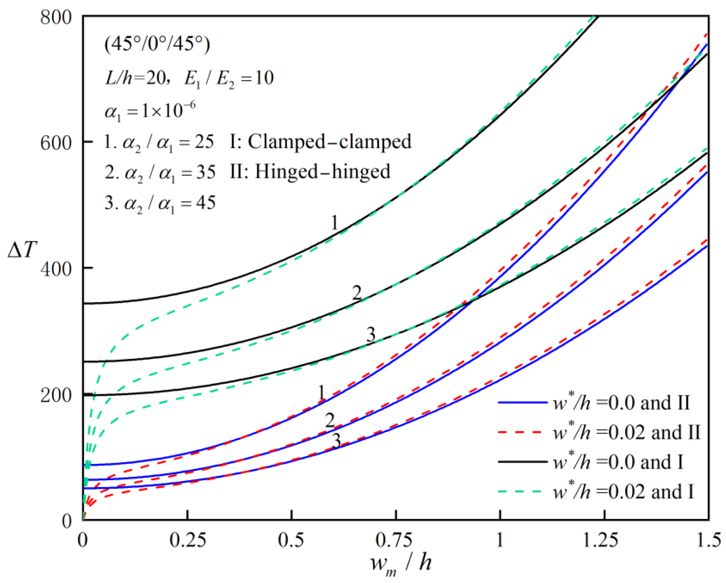
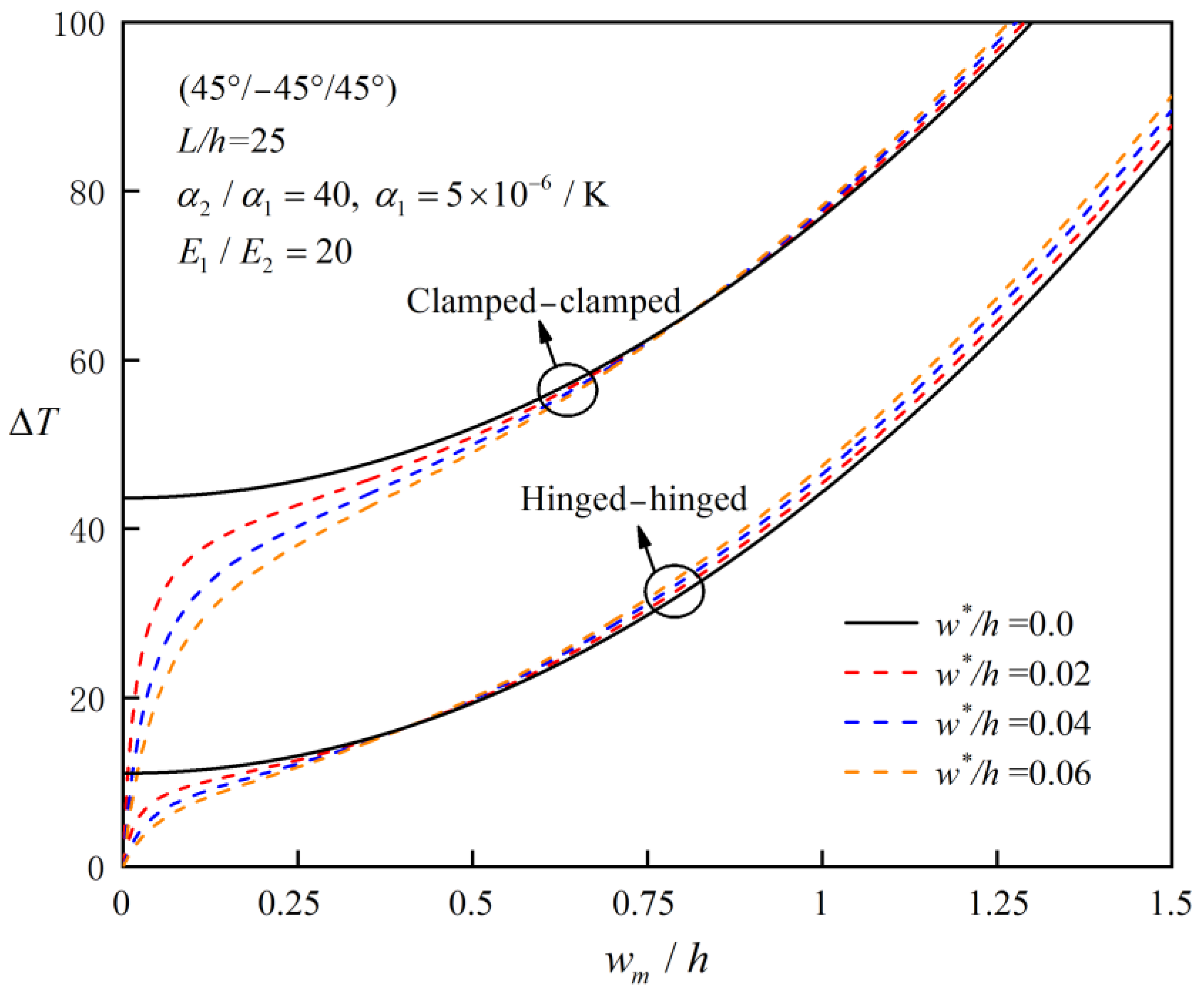
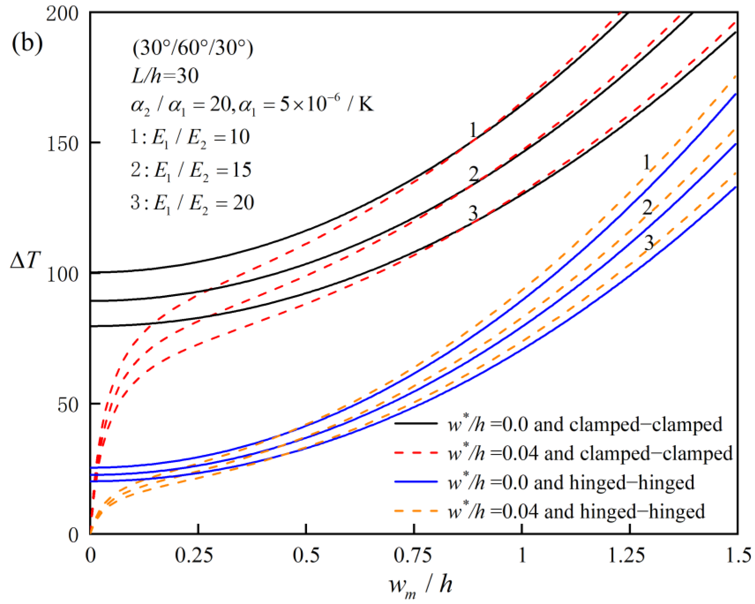
4.2. Parameter Analysis

This section again refers to the material properties of Equation (70), and numerical examples are given to analyze the various factors affecting the post-buckling characteristics of the FRC laminated beams.
Table 5 reveals that under the assumption of in-plane bending, no matter whether the laminated beams are simply supported at both ends or clamped at both ends, the antisymmetric angle-ply laminated beams have the same bifurcated equilibrium path as the symmetric angle-ply laminated beams. This phenomenon can also be verified by Equation (13); that is, the equivalent axial tension–compression stiffness and transverse shear stiffness of the two layers with same absolute values of the ply angle are equal. Therefore, we can draw a conclusion that when the beam is symmetrically or anti-symmetrically laminated, there exists the equilibrium path of bifurcation for simply supported laminated beams, while the geometric and physical neutral surfaces of the laminated beams do not coincide in other ply modes, resulting in the tension–bending coupling effect, so there is no bifurcated equilibrium path.
Figure 2 reflects the effects of the elastic modulus ratio and slenderness ratio on the critical buckling temperature of the bifurcation type for perfect FRC laminated beams with immovable clamped–clamped and hinged–hinged ends and different ply angles. From the above, it is found that for simply supported laminated beams, if the absolute values of the ply angles of the two symmetrical layers in geometry are different, there is no critical buckling value of the bifurcation type, so the buckling problem in this case is not considered. As can be seen from the figures, the critical buckling value generally increases first and then decreases with the increase in the elastic modulus ratio E 1 / E 2 , and an increase in the slenderness ratio L/h will delay the decrease in critical buckling value with the increase in the elastic modulus ratio E 1 / E 2 . For the given two boundary conditions, fixed support at both ends has higher buckling strength than simple support at both ends. One can also find that for a given number of common ply modes, when the ratio of elasticity modulus is small, [0°/45°/0°] beams have the best ability to resist instability; otherwise, [0°/90°/0°] beams are the best, while [45°/−45°/45°] and [45°/−45°] are the worst ply modes to resist buckling.
Figure 3 shows the effects of the slenderness ratio on the critical buckling temperature of the bifurcation type for perfect symmetrically layered FRC laminated beams with hinged–hinged and clamped–clamped ends. One can find that the boundary conditions have greater influence on the buckling strength than the ply angles in the case of given material parameters and that the critical buckling value of beams may decrease sharply with the increase in the slenderness ratio.
Figure 4 and Figure 5 demonstrate the effect of the thermal expansion coefficient ratio on the critical buckling temperature load and post-buckling behaviors for perfect and imperfect FRC laminated beams with different influencing factors. The numerical results suggest that with the increase in the thermal expansion coefficient ratio α 2 / α 1 , the critical buckling temperature decreases, and post-buckling load-bearing capacity decreases. Further, it can be found that the smaller the elastic modulus ratio E 1 / E 2 , the faster the buckling value decreases. It can also be found that the influence of the elastic modulus ratio on critical buckling load is not only affected by the paving angles and slenderness ratio but also by the thermal expansion coefficient ratio.
Figure 6 compares the post-buckling equilibrium path curves of (45°/−45°/45°) symmetrically laminated beams with different initial imperfection rates. As can be seen from the figure, the laminated beam structures are not sensitive to initial geometric imperfections in general, and the post-buckling equilibrium path is stable. It can be concluded that for perfectly symmetric paved laminated beams, whether simply supported or fixed at both ends, the entire equilibrium path is of the bifurcation type. With the increase in the defect rate, the bearing capacity of beams decreases at the initial post-buckling stage, but in the deep post-buckling stage, contrary to what one might expect, the initial defect rate can enhance the bending stiffness of the beam to a certain extent. Note that the equilibrium path of the bifurcation type does not exist for laminated beams with initial imperfections.
Figure 7 investigates the influence of the elastic modulus ratio E 1 / E 2 on the post-buckling equilibrium paths of symmetrically laminated beams with two different kinds of boundary conditions and ply angles. It is obvious that laminated beams with fixed ends have better post-buckling bearing capacity than simply supported beams at both ends, which can also be verified by Figure 5 and Figure 6. However, the influence of the elastic modulus ratio on the post-buckling equilibrium path of beams is also affected by the ply angles and slenderness ratio implied by Figure 2, and it is challenging to generalize the influence of the elastic modulus ratio on the post-buckling equilibrium path. It can be also found that (0°/90°/0°) beams have higher post-buckling strength than (30°/60°/30°) beams.
Figure 8 compares the post-buckling equilibrium paths of hinged–hinged and clamped–clamped laminated beams with different ply modes (symmetrically layered and asymmetrically layered). It can be obtained from Figure 8a that for perfect antisymmetric laminated beams, whether simply supported or clamped at both ends, the post-buckling equilibrium paths of the bifurcation type always exist because there is no tension–bending coupling effect in this case. However, for other asymmetric laminated beams, if both ends are simply supported, the post-buckling equilibrium path of the bifurcation type does not exist due to the existence of the thermal bending moment caused by the eccentricity of the neutral surface. From the two figures, it can be seen that (45°/−45°/45°) and (45°/−45°) beams always have the worst post-buckling bearing capacity among the given ply angles.

5. Conclusions

In this paper, a modified zig-zag beam model is used to refine the modeling of laminated beams. The thermal buckling and post-buckling behaviors of both clamped–clamped and hinged–hinged FRC laminated beams with geometric imperfections are systematically studied by using a two-step perturbation technique. Through detailed verification and parameter analysis, the main conclusions are as follows:
  • Comparison of Zig-Zag Model and Equivalent Single-Layer Theory: For symmetric or anti-symmetric laminated beams, the results of the zig-zag beam model and the equivalent single-layer theory are similar, with differences of less than 2%. However, for general asymmetric laminated beams, the zig-zag model provides more accurate predictions, especially when the slenderness ratio is small or the elastic modulus ratio is large. For example, for asymmetric (0°/90°) laminated beams with a slenderness ratio of 5, the zig-zag model predicts a critical buckling temperature of 0.511, while the equivalent single-layer theory overestimates this value by up to 10%.
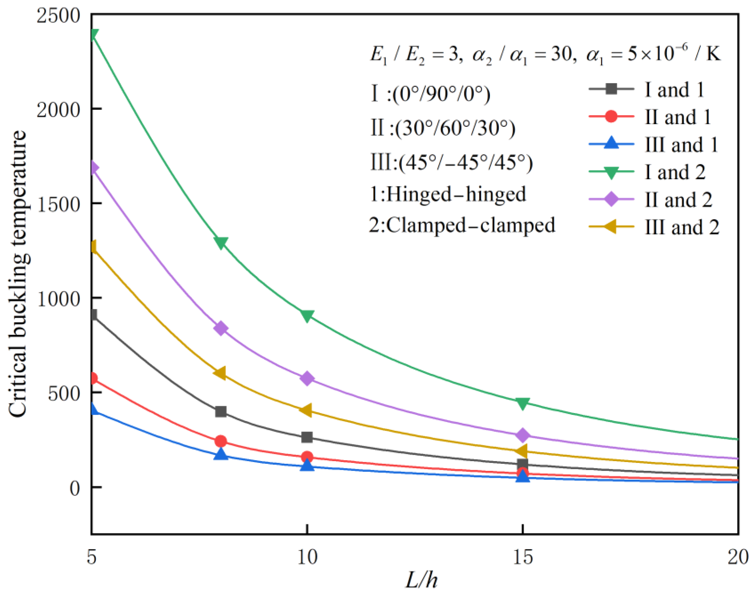
  • Effect of Slenderness Ratio: The critical buckling temperature increases with the slenderness ratio. For example, for a symmetric (0°/90°/0°) laminated beam with clamped–clamped ends, the critical buckling temperature increases from 0.682 for a slenderness ratio of 5 to 4.018 for a slenderness ratio of 50.
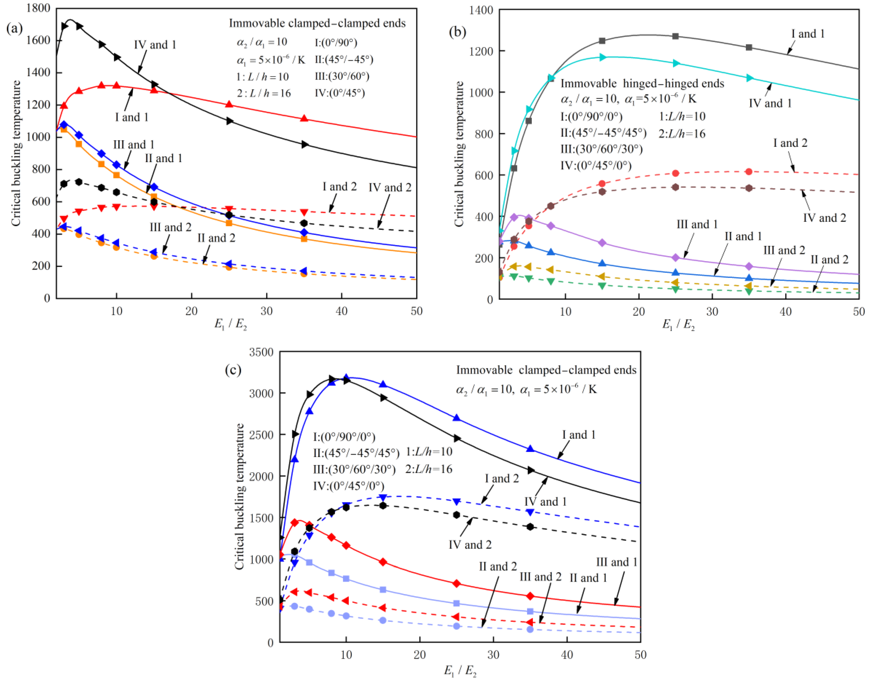
  • Effect of Elastic Modulus Ratio: The critical buckling temperature generally increases with the elastic modulus ratio, but the effect is more pronounced for beams with a small slenderness ratio. For example, for a clamped–clamped (0°/90°) laminated beam with a slenderness ratio of 10, the critical buckling temperature increases by 15% when the elastic modulus ratio increases from 3 to 10.
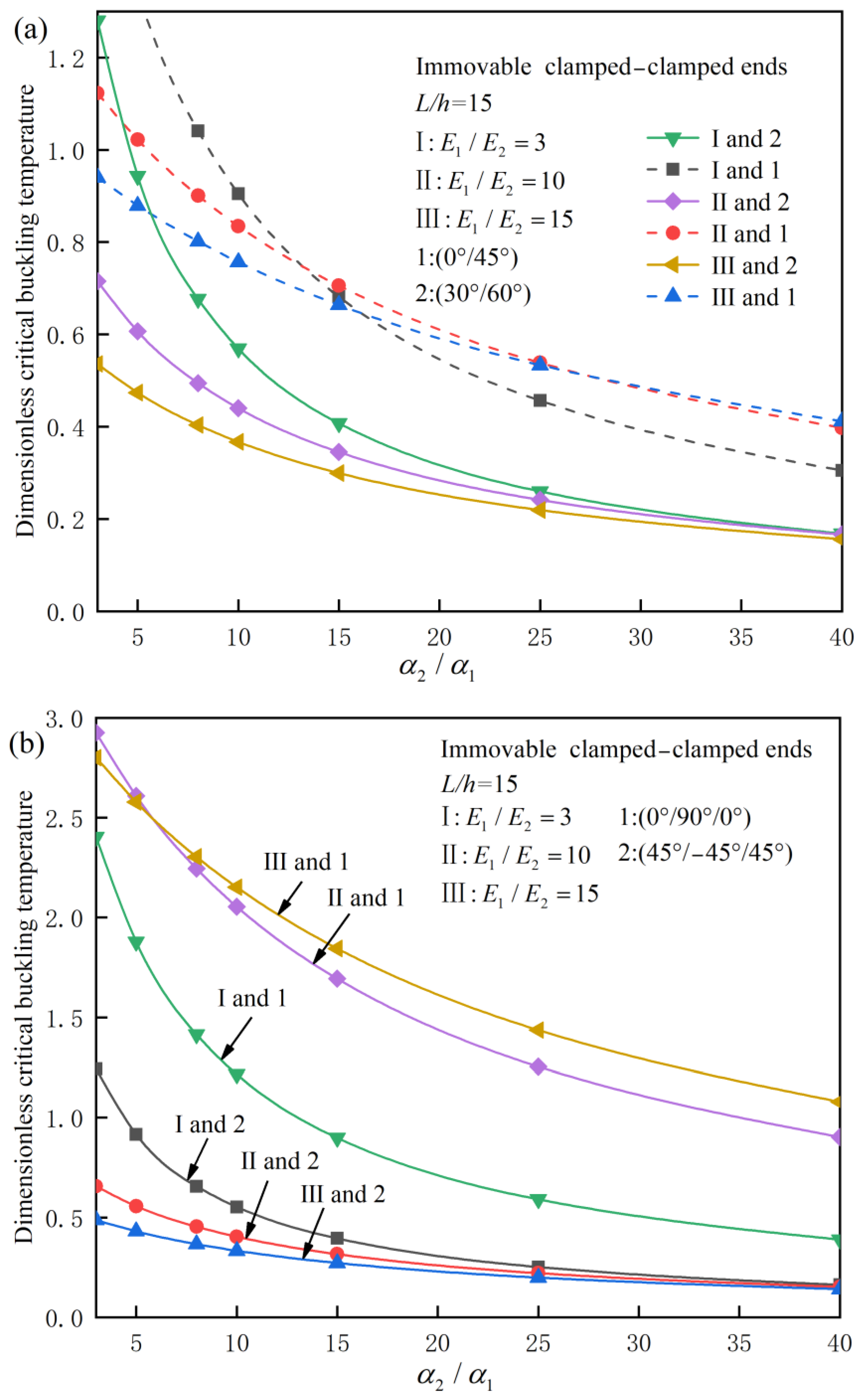
  • Effect of Thermal Expansion Coefficient Ratio: The critical buckling temperature decreases with the thermal expansion coefficient ratio. For example, for a clamped–clamped (45°/−45°/45°) laminated beam, the critical buckling temperature decreases by 20% when the thermal expansion coefficient ratio increases from 3 to 10.
  • Initial Imperfection Sensitivity: The post-buckling behavior of FRC laminated beams is relatively insensitive to initial imperfections. However, in the deep post-buckling stage, the initial defect rate can enhance the bending stiffness of the beam by up to 10% due to stress redistribution caused by the geometric imperfection.
The findings of this study have important practical implications for the design and analysis of aerospace structures. The modified zig-zag beam model can be used to predict the thermal post-buckling behavior of laminated beams with geometric imperfections, enabling engineers to design more robust and lightweight structures. The results also provide insights into the effects of material properties, boundary conditions, and geometric imperfections on the stability of laminated beams, which can inform the development of advanced composite materials for aerospace applications.

Author Contributions

Conceptualization, Z.W.; methodology, Z.W.; software, Z.W.; validation, Z.W.; formal analysis, Z.W.; investigation, Z.W.; resources, Z.W.; data curation, Z.W.; writing—original draft preparation, Z.W.; writing—review and editing, Z.W.; visualization, Z.W.; supervision, Q.M.; project administration, Q.M.; funding acquisition, Q.M. All authors have read and agreed to the published version of the manuscript.

Funding

This research received no external funding.

Data Availability Statement

All data analyzed during this study are presented in this article.

Conflicts of Interest

The authors declare no conflicts of interest.

References

  1. Hudson, T.B.; Auwaijan, N.; Yuan, F.G. Guided wave-based system for real-time cure monitoring of composites using piezoelectric discs and phase-shifted fiber Bragg gratings. J. Compos. Mater. 2019, 53, 969–979. [Google Scholar] [CrossRef] [PubMed]
  2. Barile, C.; Casavola, C.; Cililis, F.D. Mechanical comparison of new composite materials for aerospace applications. Compos. Part B 2019, 162, 122–128. [Google Scholar] [CrossRef]
  3. Liu, X.; Sun, W.; Yan, X.; Du, D.; Liu, H.; Li, H. Nonlinear vibration analysis of carbon fiber-reinforced composites with frequency-dependence and strain-dependence: Experimental and theoretical studies. Thin-Walled Struct. 2023, 183, 110369. [Google Scholar] [CrossRef]
  4. Christian, W.J.R.; DiazDelaO, F.A.; Patterson, E.A. Strain-based damage assessment for accurate residual strength prediction of impacted composite laminates. Compos. Struct. 2018, 184, 1215–1223. [Google Scholar] [CrossRef]
  5. Jiang, H.; Ren, Y.; Zhang, S.; Liu, Z.; Yu, G.; Xiang, J. Damage and perforation resistance behaviors induced by projectile impact load on bonding-patch repaired and scarf-patch repaired composite laminates. Int. J. Damage Mech. 2019, 28, 502–537. [Google Scholar] [CrossRef]
  6. Eltaher, M.A.; Mohamed, N.; Mohamed, S.A.; Seddek, L. Periodic and nonperiodic modes of postbuckling and nonlinear vibration of beams attached to nonlinear foundations. Appl. Math. Model. 2019, 75, 414–445. [Google Scholar] [CrossRef]
  7. Yu, Y.; Shen, H.S.; Wang, H.; Hui, D. Postbuckling of sandwich plates with graphene-reinforced composite face sheets in thermal environments. Compos. Part B Eng. 2018, 135, 72–83. [Google Scholar] [CrossRef]
  8. Li, Z.M.; Qiao, P. Thermal postbuckling analysis of anisotropic laminated beams with different boundary conditions resting on two-parameter elastic foundations. Eur. J. Mech. A/Solids 2015, 54, 30–43. [Google Scholar] [CrossRef]
  9. Wu, H.L.; Yang, J.; Kitipornchai, S. Imperfection sensitivity of postbuckling behaviour of functionally graded carbon nanotube-reinforced composite beams. Thin-Walled Struct. 2016, 108, 225–233. [Google Scholar] [CrossRef]
  10. Shen, H.S.; Reddy, J.N.; Yu, Y. Postbuckling of doubly curved FG-GRC laminated panels subjected to lateral pressure in thermal environments. Mech. Adv. Mater. Struct. 2021, 28, 260–270. [Google Scholar] [CrossRef]
  11. Wu, H.L.; Zheng, Z.Q.; Guo, J.; Bao, Y.; Yang, J. Axisymmetric thermal postbuckling of functionally graded graphene nanocomposite annular plates with various geometric imperfections. Thin-Walled Struct. 2023, 185, 110594. [Google Scholar] [CrossRef]
  12. Nam, V.H.; Doan, C.V.M.; Phuong, N.T. A new analytical approach to the nonlinear buckling and postbuckling behavior of functionally graded graphene reinforced composite laminated cylindrical, parabolic, and half-sinusoid shallow imperfect panels. Polym. Compos. 2023, 44, 8928–8945. [Google Scholar] [CrossRef]
  13. Li, Z.M.; Yang, D.Q. Thermal postbuckling analysis of anisotropic laminated beams with tubular cross-section based on higher-order theory. Ocean Eng. 2016, 115, 93–106. [Google Scholar] [CrossRef]
  14. Yaghoobi, H.; Torabi, M. Post-buckling and nonlinear free vibration analysis of geometrically imperfect functionally graded beams resting on nonlinear elastic foundation. Appl. Math. Model. 2013, 37, 8324–8340. [Google Scholar] [CrossRef]
  15. Mohammadi, H.; Mahzoon, M.; Mohammadi, M.; Mohammadi, M. Postbuckling instability of nonlinear nanobeam with geometric imperfection embedded in elastic foundation. Nonlinear Dyn. 2014, 76, 2005–2016. [Google Scholar] [CrossRef]
  16. Fan, Y.; Wang, H. Nonlinear bending and postbuckling analysis of matrix cracked hybrid laminated plates containing carbon nanotube reinforced composite layers in thermal environments. Compos. Part B Eng. 2016, 86, 1–16. [Google Scholar] [CrossRef]
  17. Reddy, J.N. A simple higher-order theory for laminated composite plates. J. Appl. Mech. 1984, 51, 745–752. [Google Scholar] [CrossRef]
  18. Thai, C.H.; Ferreira, A.J.M.; Nguyen-Xuan, H. Isogeometric analysis of size-dependent isotropic and sandwich functionally graded microplates based on modified strain gradient elasticity theory. Compos. Struct. 2018, 192, 274–288. [Google Scholar] [CrossRef]
  19. Amabili, M.; Breslavsky, I.D.; Reddy, J.N. Nonlinear higher-order shell theory for incompressible biological hyperelastic materials. Comput. Methods Appl. Mech. Eng. 2019, 346, 841–861. [Google Scholar] [CrossRef]
  20. Kefal, A.; Hasim, K.A.; Yildiz, M. A novel isogeometric beam element based on mixed form of refined zigzag theory for thick sandwich and multilayered composite beams. Compos. Part B Eng. 2019, 167, 100–121. [Google Scholar] [CrossRef]
  21. Carrera, E.; Boscolo, M. Classical and mixed finite elements for static and dynamic analysis of piezoelectric plates. Int. J. Numer. Methods Eng. 2010, 70, 1135–1181. [Google Scholar] [CrossRef]
  22. Panteghini, A.; Bardella, L. Structural theory and finite element modelling of linear elastic sandwich beams subject to severe boundary conditions. Eur. J. Mech. A/Solids 2017, 61, 393–407. [Google Scholar] [CrossRef]
  23. Murakami, H. Laminated Composite Plate Theory with Improved In-Plane Responses. J. Appl. Mech. 1986, 53, 661. [Google Scholar] [CrossRef]
  24. Carrera, E. On the use of the Murakami’s zig-zag function in the modeling of layered plates and shells. Comput. Struct. 2004, 82, 541–554. [Google Scholar] [CrossRef]
  25. Xie, F.; Qu, Y.; Zhang, W.; Peng, Z.; Meng, G. Nonlinear aerothermoelastic analysis of composite laminated panels using a general higher-order shear deformation zig-zag theory. Int. J. Mech. Sci. 2019, 150, 226–237. [Google Scholar] [CrossRef]
  26. Su, J.; Kai, Z.; Qu, Y.; Hua, H. A variational formulation for vibration analysis of curved beams with arbitrary eccentric concentrated elements. Arch. Appl. Mech. 2018, 88, 1089–1104. [Google Scholar] [CrossRef]
  27. Chanda, A.G.; Kontoni, D.P.N.; Sahoo, R. Development of analytical and FEM solutions for static and dynamic analysis of smart piezoelectric laminated composite plates on elastic foundation. J. Eng. Math. 2023, 138, 12. [Google Scholar] [CrossRef]
  28. Yang, S.W.; Hao, Y.X.; Zhang, W.; Ma, W.S.; Wu, M.Q. Nonlinear Frequency and Bifurcation of Carbon Fiber-Reinforced Polymer Truncated Laminated Conical Shell. J. Vib. Eng. Technol. 2024, 12, 457–468. [Google Scholar] [CrossRef]
  29. Mohammadrezazadeh, S.; Jafari, A.A. Nonlinear vibration suppression of laminated composite conical shells on elastic foundations with magnetostrictive layers. Compos. Struct. 2021, 258, 113323. [Google Scholar] [CrossRef]
  30. Li, X.; Qin, Y.; Zhou, Z.H. Coupled Vibration Analysis of Rotating Composite Laminated Beams in Hygrothermal Environment Using the Green’s Function Method. Int. J. Struct. Stab. Dyn. 2023, 23, 2350016. [Google Scholar] [CrossRef]
  31. Yadav, A.; Amabili, M.; Panda, S.K.; Dey, T. Instability analysis of fluid-filled angle-ply laminated circular cylindrical shells subjected to harmonic axial loading. Eur. J. Mech. A/Solids 2023, 97, 104810. [Google Scholar] [CrossRef]
  32. Thai, C.H.; Nguyen-Xuan, H. A moving kriging interpolation meshfree method based on naturally stabilized nodal integration scheme for plate analysis. Int. J. Comput. Methods 2019, 16, 1850100. [Google Scholar] [CrossRef]
  33. Yang, S.C.; Yao, Y.; Li, Y.C.; Ma, L.; Zhang, Y.; Yang, Q. Geometrically Nonlinear Random Response of Stiffened Laminated Plates by Proper-Orthogonal-Decomposition-Based Reduced-Order Modeling. AIAA J. 2022, 60, 1861–1872. [Google Scholar] [CrossRef]
  34. Nazemizadeh, M.; Bakhtiari-Nejad, F.; Assadi, A. Size-dependent nonlinear dynamic modeling and vibration analysis of piezo-laminated nanomechanical resonators using perturbation method. Arch. Appl. Mech. 2020, 90, 1659–1672. [Google Scholar] [CrossRef]
  35. Carrera, E.; Valvano, S.; Filippi, M. Classical, higher-order, zig-zag and variable kinematic shell elements for the analysis of composite multilayered structures. Eur. J. Mech. A/Solids 2018, 72, 97–110. [Google Scholar] [CrossRef]
  36. Sahoo, R.; Singh, B.N. A new trigonometric zigzag theory for static analysis of laminated composite and sandwich plates. Aerosp. Sci. Technol. 2014, 35, 15–28. [Google Scholar] [CrossRef]
  37. Marguerre, K.; Woemle, H.T. Elastic Plates; Blaisdell Publishing Company: New York, NY, USA, 1969. [Google Scholar]
  38. Emam, S.; Eltaher, M.A. Buckling and postbuckling of composite beams in hygrothermal environments. Compos. Struct. 2016, 152, 665–675. [Google Scholar] [CrossRef]
  39. Shen, H.S.; Lin, F.; Xiang, Y. Nonlinear bending and thermal postbuckling of functionally graded graphene-reinforced composite laminated beams resting on elastic foundations. Eng. Struct. 2017, 140, 89–97. [Google Scholar] [CrossRef]
  40. Shen, H.S. Nonlinear analysis of functionally graded fiber reinforced composite laminated beams in hygrothermal environments, Part I: Theory and solutions. Compos. Struct. 2015, 125, 698–705. [Google Scholar] [CrossRef]
  41. Babaei, H.; Kiani, Y.; Eslami, M.R. Thermal buckling and post-buckling analysis of geometrically imperfect FGM clamped tubes on nonlinear elastic foundation. Appl. Math. Model. 2019, 71, 12–30. [Google Scholar] [CrossRef]
  42. She, G.L.; Yuan, F.G.; Ren, Y.R.; Xiao, W.S. On buckling and postbuckling behavior of nanotubes. Int. J. Eng. Sci. 2017, 121, 130–142. [Google Scholar] [CrossRef]
  43. Nguyen, N.D.; Nguyen, T.K.; Nguyen, T.N.; Thai, H.T. New Ritz-solution shape functions for analysis of thermo-mechanical buckling and vibration of laminated composite beams. Compos. Struct. 2018, 184, 452–460. [Google Scholar] [CrossRef]
  44. Aydogdu, M. Thermal buckling analysis of cross-ply laminated composite beams with general boundary conditions. Compos. Sci. Technol. 2007, 67, 1096–1104. [Google Scholar] [CrossRef]
Figure 1. Geometry of the laminated beam consisting of N plies.
Aerospace 12 00138 g001
Figure 2. Effects of the elastic modulus ratio and slenderness ratio on the critical buckling temperature of the bifurcation type for perfect FRC laminated beams with different ply angles: (a) asymmetrically layered beam with clamped–clamped ends; (b) symmetrically layered beam with hinged–hinged ends; (c) symmetrically layered beam with clamped–clamped ends.
Aerospace 12 00138 g002
Figure 3. Effects of the slenderness ratio on the critical buckling temperature of the bifurcation type for perfect symmetrically layered FRC laminated beams.
Aerospace 12 00138 g003
Figure 4. Effects of the thermal expansion coefficient ratio on the critical buckling temperature of the bifurcation type for perfect clamped–clamped FRC laminated beams with different ply modes and elastic modulus ratios: (a) asymmetrically layered; (b) symmetrically layered.
Aerospace 12 00138 g004
Figure 5. Effect of different thermal expansion coefficient ratios on the thermal post-buckling behaviors of (45°/0°/45°) symmetrically layered FRC laminated beams under two different boundary conditions.
Aerospace 12 00138 g005
Figure 6. Effects of different initial imperfection rates on the thermal post-buckling behaviors for (45°/−45°/45°) symmetrically layered FRC laminated beams.
Aerospace 12 00138 g006
Figure 7. Effects of different elastic modulus ratios on the thermal post-buckling behaviors for symmetrically layered FRC laminated beams for two different kinds of boundary conditions and ply angles: (a) (0°/90°/0°); (b) (30°/60°/30°).
Aerospace 12 00138 g007aAerospace 12 00138 g007b
Figure 8. Effect of different ply modes on the thermal post-buckling behaviors of FRC laminated beams: (a) asymmetrically layered; (b) symmetrically layered.
Aerospace 12 00138 g008aAerospace 12 00138 g008b
Table 1. Dimensionless critical buckling temperature of (0°/90°) C-C asymmetric FRC laminated beams ( E 1 / E 2 = 20 ,   α 2 / α 1 = 3 ) [43,44].
L/hReference(0°/90°)
5Present0.511
Ngoc-Duong Nguyen [44]0.558
Aydogdu [43]0.557
Khdeir 0.583
FOSDT0.505
10Present0.850
Ngoc-Duong Nguyen [44]0.887
Khdeir 0.926
FOSDT0.841
20Present1.029
Ngoc-Duong Nguyen [44]1.045
Aydogdu [43]1.092
Khdeir 1.090
FOSDT1.017
30Present1.071
Ngoc-Duong Nguyen [44] 1.081
FOSDT1.063
50Present1.094
Ngoc-Duong Nguyen [44]1.100
Aydogdu [43]1.098
Khdeir 1.148
FOSDT1.086
Table 2. Dimensionless critical buckling temperature of (0°/90°/0°) symmetric FRC laminated beams ( E 1 / E 2 = 20 ,   α 2 / α 1 = 3 ) [43,44].
L/hReferenceBCs
H-HC-C
5Present0.4480.682
Ngoc-Duong Nguyen [44]0.4500.682
Khdeir 0.4680.710
FOSDT0.4390.675
10Present0.7871.791
Ngoc-Duong Nguyen [44]0.7911.798
Aydogdu [43]0.791.797
Khdeir 0.8231.871
FOSDT0.7721.791
20Present0.9763.149
Ngoc-Duong Nguyen [44]0.9793.163
Khdeir 1.0193.292
FOSDT0.9623.133
30Present1.0213.674
Ngoc-Duong Nguyen [44]1.0253.680
FOSDT1.0133.656
50Present1.0464.018
Ngoc-Duong Nguyen [44]1.0494.032
Aydogdu [43]1.0494.030
Khdeir 1.0924.196
FOSDT1.0374.006
Table 3. Dimensionless critical buckling temperature of (0°/90°) C-C asymmetric FRC laminated beams (L/h = 10) [43].
BCs E 1 / E 2 Reference α 2 / α 1
3102050100
C-C3Present1.3420.5960.3330.1430.073
Ngoc-Duong Nguyen1.3680.6080.3390.1460.075
10Present1.0710.6590.4250.2060.111
Ngoc-Duong Nguyen1.0900.6710.4330.2100.113
20Present0.8500.6230.4510.2470.141
Ngoc-Duong Nguyen0.8870.6500.4710.2570.147
40Present0.6430.5370.4340.2760.171
Ngoc-Duong Nguyen0.7090.5920.4780.3040.189
Table 4. Dimensionless critical buckling temperature of (0°/90°/0°) symmetric FRC laminated beams (L/h = 10) [43,44].
BCs E 1 / E 2 Reference α 2 / α 1
3102050100
H-H3 Present0.624 0.316 0.185 0.083 0.043
Ngoc-Duong Nguyen0.637 0.322 0.171 0.084 0.044
Aydogudu0.637 0.323 0.189 0.293 0.153
10 Present0.815 0.573 0.402 0.212 0.119
Ngoc-Duong Nguyen 0.821 0.576 0.404 0.213 0.119
20 Present0.787 0.638 0.502 0.306 0.185
Ngoc-Duong Nguyen0.791 0.641 0.504 0.307 0.186
Khdeir 0.823 0.708 0.590 0.393 0.253
40 Present0.663 0.590 0.510 0.362 0.244
Ngoc-Duong Nguyen0.666 0.592 0.512 0.363 0.245
C-C3 Present2.170 1.098 0.643 0.287 0.149
Ngoc-Duong Nguyen 2.212 1.119 0.656 0.293 0.137
10 Present2.263 1.589 1.115 0.588 0.329
Ngoc-Duong Nguyen2.278 1.599 1.122 0.592 0.331
20 Present1.791 1.451 1.141 0.695 0.421
Ngoc-Duong Nguyen1.798 1.456 1.145 0.698 0.423
Aydogudu1.804 1.462 1.148 0.699 0.423
40 Present1.216 1.082 0.935 0.664 0.448
Ngoc-Duong Nguyen1.218 1.083 0.936 0.665 0.448
Table 5. Comparison of equilibrium paths of perfect symmetrically and anti-symmetrically layered beams α 1 = 1 × 10 6 / K , α 2 / α 1 = 25 , E 1 / E 2 = 15 ,   L / h = 20 .
BCsw/hPly Angle
(30°/−30°)(30°/30°)(45°/0°/45°)(45°/0°/−45°)
H-H0233.816233.816177.947177.947
0.2262.185262.185243.095243.095
0.4347.293347.293438.536438.536
0.6 489.138489.138764.271764.271
0.8687.722687.7221220.3011220.301
1.0 943.044943.0441806.6251806.625
1.21255.1041255.1042523.2432523.243
1.41623.9031623.9033370.1553370.155
C-C0 905.482905.482691.368691.368
0.2933.852933.852756.515756.515
0.41018.9591018.959951.957951.957
0.61160.8041160.8041277.6921277.692
0.81359.3881359.3881733.7221733.722
1.01614.7101614.7102320.0462320.046
1.21926.7711926.7713036.6643036.664
1.42295.5692295.5693883.5763883.576
Disclaimer/Publisher’s Note: The statements, opinions and data contained in all publications are solely those of the individual author(s) and contributor(s) and not of MDPI and/or the editor(s). MDPI and/or the editor(s) disclaim responsibility for any injury to people or property resulting from any ideas, methods, instructions or products referred to in the content.

