1. Introduction
The aeromechanical stability problem of a helicopter is caused by the coupling effect between the flapping and lagging motions of the rotor, and the pitching and rolling motions of the fuselage. When the helicopter is operating on the ground, the problem is known as the ground resonance, and can cause devastating accidents [
1]. When the helicopter is operating in the air, the problem is known as the air resonance, and affects flight safety [
2]. Many studies on the ground resonance and air resonance of a helicopter have been conducted to improve the stability through various passive and active methods [
3,
4,
5,
6,
7,
8]. But the author did not find any public literature in English on the aeromechanical stability of a helicopter that is ground taxiing.
Taxiing takeoff is very important for heavy-lift helicopters. When heavy-lift helicopters are overloaded or located in high-altitude areas, it is often necessary to use ground taxiing to reduce the required power of the helicopter and achieve takeoff. But the mechanical characteristics of the landing gear wheel change with the taxiing speed means it is easy to cause the landing gear shimmy instability [
9,
10]. In addition, the rotor aerodynamic forces when helicopter ground taxiing also makes the aeromechanical stability issues of the rotor/fuselage coupling system when helicopter ground taxiing fundamentally different from those of helicopter in the ground static state and aerial flight state. When a helicopter is taxiing, the lateral stiffness of the landing gear wheels decreases with increasing taxiing speed, and the lateral modal frequency of the fuselage also decreases. This will cause the unstable boundary of the rotor operating speed, which was originally higher than the rotor operating speed, to fall within the rotor operating speed, resulting in ground resonance [
11]. Therefore, it is necessary to analyze the aeromechanical stability of the rotor/fuselage coupling system when helicopter ground taxiing. When a helicopter is taxiing on the ground, the longitudinal cyclic input from the pilot’s control stick and the taxiing speed cause an asymmetric airflow environment around the rotor, resulting in cyclic flapping and lagging motions of the blades, which means the flapping and lagging modes of the blades play an important role in the aeromechanical stability of the rotor/fuselage coupling system.
Studies [
12,
13,
14] about helicopter ground taxiing have mainly focused on establishing dynamic models and optimizing the control strategy to reduce the taxiing distance. Sugiura et al. [
15] calculated the wake of a rotor under different taxiing speeds, considering the ground effects. Akkaya and Bal [
16] considered the influence of taxiing speed on the stiffness and damping of the landing gear wheels, established the buffer/wheel coupling model of the landing gear wheels, and analyzed the effects of the helicopter taxiing speeds, landing gear loads, and buffer hydraulic oil viscosity on the shimmy stability of the wheels. Volodko [
17] proposed a dynamic model of a taxiing helicopter, with tricycle landing gear wheels, and calculated the influence of helicopter weight on the attitude changes in the helicopter during taxiing takeoff to avoid the risk of rollover during the taxiing.
Based on the literature review, previous research on the aeromechanical stability of a helicopter that is ground taxiing has only considered a limited number of degrees of freedom of system motion in modeling, with little consideration of the aerodynamic effects of the rotor, which cannot fully reflect the characteristics of the aeromechanical stability of helicopter taxiing. Ormiston [
18] pointed out that if the aerodynamic forces were considered in the analysis of helicopter ground resonance, air resonance would have a significant influence on the calculation results. In this paper, the aeromechanical dynamics model and stability calculation method for the rotor/fuselage coupling system, considering the aerodynamic forces of blades, the flapping and lagging motions of blades, as well as the pitching, rolling, and lateral motions of fuselage in helicopter ground taxiing, have been presented. Taking the Z-8 helicopter as an example, the modal frequencies and damping that vary with the taxiing speeds are calculated and the influences of the aerodynamic forces of blades on the calculation results are analyzed.
2. Aeromechanical Dynamics Modeling of Helicopter When Ground Taxiing
When establishing the analytical model of the rotor/fuselage coupling system in helicopter ground taxiing, the blade and fuselage are assumed as rigid bodies. Considering the flapping and lagging motions of the blades, as well as the pitching, rolling, and lateral motions of the fuselage, the dynamic equations of the rotor/fuselage coupling system are derived based on Hamilton’s principle, which is as follows:
where
and
are the variations in the strain energy and the kinematic energy.
is the virtual work of external, non-conservative forces applied to the system. They are expressed from the rotor and the fuselage, as follows:
where the subscripts R, F, and
k denote the rotor, the fuselage, and the
blade, respectively, and
is the number of blades. The variation in the strain energy of the
blade
is provided by the restraint springs at the flapping and lagging hinges. The variation in the strain energy of the fuselage
is provided by the landing gears. The variations in the virtual works of the
blade
and the fuselage
originate from the lag damper and the landing gear, respectively.
is the variation in the virtual work performed by aerodynamic forces on the
blade.
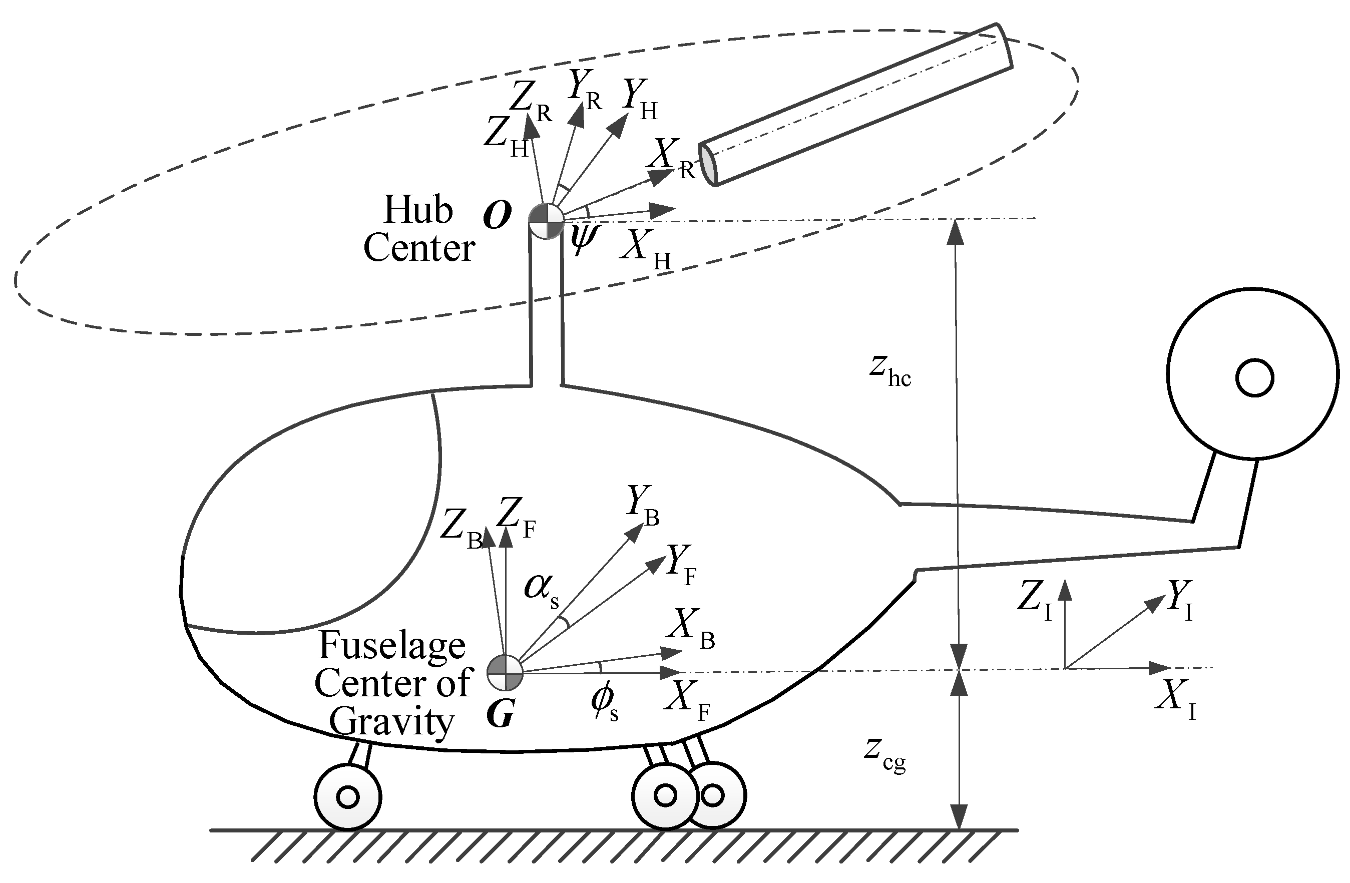
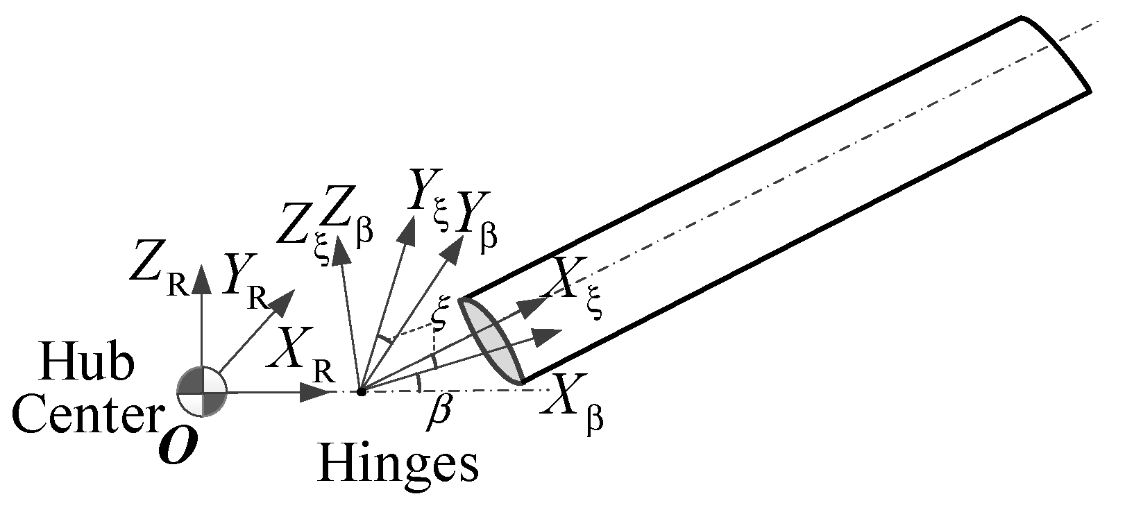
To derive the variation in the kinematic energy and the aerodynamic virtual work, seven coordinate systems are needed to describe the motion of an arbitrary point on the rotating blade. As shown in
Figure 1 and
Figure 2, they are the ground inertial coordinate system
, the fuselage inertial coordinate system
, the fuselage coordinate system
, the hub-fixed coordinate system
, the rotating blade coordinate system
, the blade flapping coordinate system
, and the blade lagging coordinate system
.
and
are the pitching and rolling angles of the fuselage;
and
are the flapping and lagging angles of the blade;
is the azimuth of the blade; and
and
are the vertical distances from the center of gravity of the fuselage
G and the hub center
O to the ground, respectively.
The position vector of an arbitrary point on the blade in the ground inertial coordinate system is as follows:
where
,
,
,
, and
are the transformation matrices between different coordinate systems,
is the offset of the flapping and lagging hinges from the hub center, and
is the fuselage lateral displacement. The velocity vector of an arbitrary point on the blade in the ground inertial coordinate system
can be obtained by differentiating Equation (5) with respect to time. Then, the virtual kinetic energy of the
blade can be derived as follows:
When a helicopter is taxing on the ground, the lateral stiffness and damping provided by the landing gear wheels change with the taxing speed and affect the modal characteristics of its fuselage. The coefficients of the lateral stiffness and damping related to the taxing speed can be expressed as follows [
12]:
where
and
are the lateral stiffness and damping coefficients provided by the landing gear wheels in the static state,
is the taxiing speed,
is the radius of the landing wheel, and
is the lateral modal frequency of the fuselage. As the rolling friction force of the landing gear wheel does not change significantly in the range of the taxiing speed and the rotor thrust does not change with the taxiing speed for the rotor coupled trim calculation, the influences of the taxiing speed on the longitudinal and vertical stiffness and damping of the landing gear wheel are limited and can be ignored. The lateral force and the rolling moment of the fuselage provided by the tricycle landing gear wheel can be written as follows:
where
,
, and
is the half of the distance between the main wheels. The subscripts 1 and 2 denote the nose wheel and the main wheel, respectively. The stiffness and damping provided by the landing gear wheel for the lateral and rolling motion of the fuselage can be written in matrix forms, as follows:
where the subscript LG represents the landing gear wheel. It can be seen from Equation (7) that, for the dynamic model of landing gear wheel considering taxiing speed, the lateral stiffness provided by the landing gear wheel is influenced by the lateral modal frequency of the fuselage
. Meanwhile, Equation (11) shows that the lateral modal frequency of the fuselage is influenced by the lateral stiffness provided by the landing gear wheel. Therefore, an iterative calculation is needed to determine the lateral modal frequency of the fuselage under different taxiing speeds.
As the taxiing speed of a helicopter is much lower than the flight speed, the unsteadiness of aerodynamic forces is not considered, and the quasi-steady aerodynamic model of the two-dimensional blade section [
19] and the Drees inflow model of rotor [
20] are used to determine the aerodynamic loads, such as lift and drag, on the blade section. In order to derive the aerodynamic virtual work of the blade
, the aerodynamic loads need to be determined. The aerodynamic loads of the blade are directly affected by the airflow velocity. By transforming the motion velocity
at the three-quarter chord of the blade section in the inertial coordinate system into the blade lagging coordinate system, the airflow velocity caused by the blade motion can be obtained as follows:
In addition to the airflow velocity caused by the blade motion, the helicopter taxiing speed
and the rotor inflow
can also cause the airflow velocity at the three-quarter chord of the blade section, as follows:
In the Drees inflow model, the inflow of rotor at the azimuth angle
and the radial station
can be expressed as follows:
where
,
, the advance ratio
, and the skew angle
. The time-averaged inflow
needs to be calculated using the Newton–Raphson algorithm to solve the following equation iteratively:
where
is the rotor thrust. Then, the resultant velocity of the airflow in the blade lagging coordinate system can be obtained as follows:
The lift and drag of the quasi-steady aerodynamic model of the two-dimensional blade section are calculated as follows:
where
is the air density,
is the chord length of the blade section. The lift coefficient
and the drag coefficient
can be expressed as follows:
where
,
,
,
, and
are the aerodynamic parameters varying with airfoils, and
is the angle of attack of the blade section. In addition to the influence of the airflow on the blade section, the influence of the pitch angle of blade
also needs to be considered. Therefore, the angle of attack of the blade section is as follows:
where the pitch angle of blade
is given by
where
is the collective pitch angle at 75% radius;
and
are, respectively, the lateral and longitudinal cyclic pitch angles; and
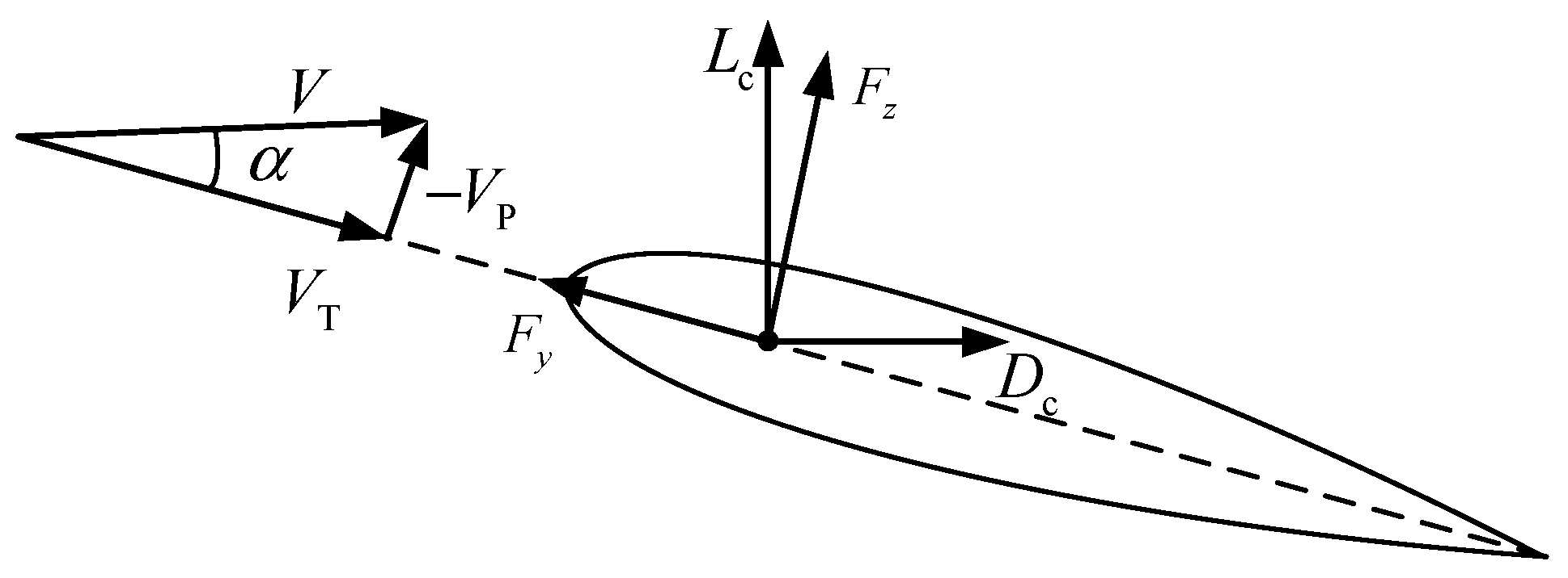
is the blade linear pretwist. As shown in
Figure 3, by decomposing the aerodynamic lift and drag of the blade section into the blade lagging coordinate system, and using the small angle assumption, i.e.,
and
, the aerodynamic forces in the lagging and flapping directions can be obtained, respectively, as follows:
Figure 3.
Schematic of aerodynamic forces of blade section.
Figure 3.
Schematic of aerodynamic forces of blade section.
Substituting Equations (13)–(21) into Equation (22), the detailed expressions of the aerodynamic forces
and
can be obtained. Further, the virtual work performed by aerodynamic forces on the blade
can be obtained, as follows:
Substituting Equations (6), (11), (12), and (23) into Equations (1)–(4), the dynamic equations of the rotor/fuselage coupling system when ground taxiing can be obtained, as follows:
where
M is the mass matrix,
C is the damping matrix,
K is the stiffness matrix, and
F is the force vector. The subscripts R and F refer to the rotor and the fuselage terms. The subscripts RF and FR refer to the rotor/fuselage coupled terms. The damping of the blade lag motion mainly originates from the inner materials of the blade and the auxiliary lag damper in rotor system. Their contribution to the lag motion of the blade is directly added to the diagonal elements in the damping matrix of the rotor, which are related to the lagging degree of freedom. The process to derive the expressions of the mass, damping, and stiffness matrices can be referred to the process in references [
21,
22].
3. Analytical Method for Aeromechanical Stability of Helicopter That Is Ground Taxiing
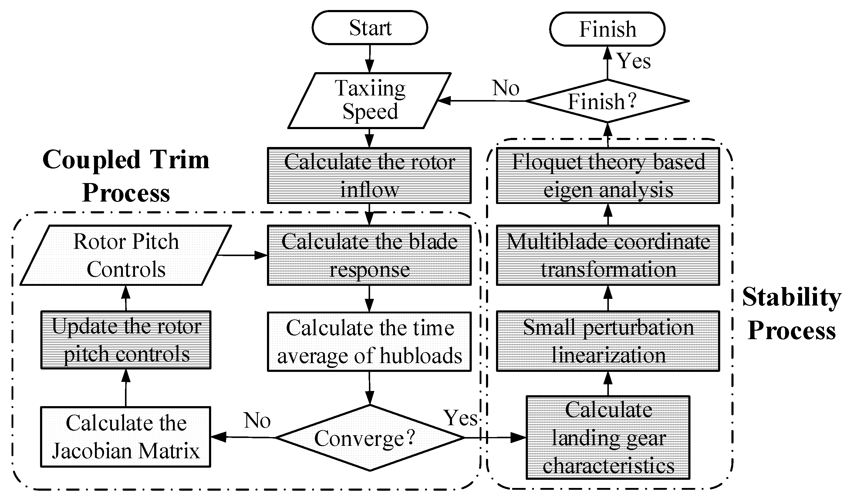
After establishing the dynamic model of a helicopter that is ground taxiing, it is necessary to establish the analytical method of the aeromechanical stability of the helicopter when ground taxiing. The whole analytical process is shown in
Figure 4.
Firstly, the rotor coupling trim calculation in helicopter taxiing is performed to determine the rotor pitch controls at a given taxiing speed. As the helicopter is being operated on the ground, the pitching and rolling angles of fuselage, as well as the collective pitch of the tail rotor, are not considered for the trim calculation. Only the collective, lateral, and longitudinal pitch controls of the rotor are iteratively calculated, using the Newton–Raphson algorithm. In each iteration, the blade response and the hub loads corresponding to the current rotor pitch controls are calculated to determine whether the rotor thrust coefficient and hub moment coefficients meet the following convergence requirement:
where
,
, and
are the calculated results of the rotor thrust coefficient, roll moment coefficient, and pitch moment coefficient, respectively.
is the rotor thrust coefficient used in the calculation of the rotor inflow coefficient in the Drees inflow model at the beginning of the rotor coupling trim calculation. If they have not converged yet, the Jacobian matrix of the hub loads vector concerning the rotor pitch controls need to be computed, as follows:
The terms in the Jacobian matrix are obtained by using the forward finite difference approximation at the initial controls. The incremental pitch control vector at the
ith iterative step is given by
Then, the rotor pitch controls are updated by using the following equation:
where
is a relaxation factor to improve the convergence speed.
Secondly, the stability analysis is conducted via the following steps: (1) iteratively calculating the stiffness and damping in the lateral and rolling directions provided by the landing gear wheels at the taxiing speed, using Equations (7)–(12) to make the assumed value of
in Equation (7) equal the lateral modal frequency of the fuselage calculated by solving the free vibration equations of fuselage; (2) performing small perturbation linearization of the rotor/fuselage coupling equation near the trim solution; (3) transforming the perturbation equations to the fixed coordinate system, using the multi-blade coordinate transformation; and (4) eigenvalue analyzing, using the Floquet theory [
23,
24] to determine the modal frequencies and the damping of the rotor/fuselage coupling system.
In this paper, an example of the ground resonance of a hingeless rotor helicopter [
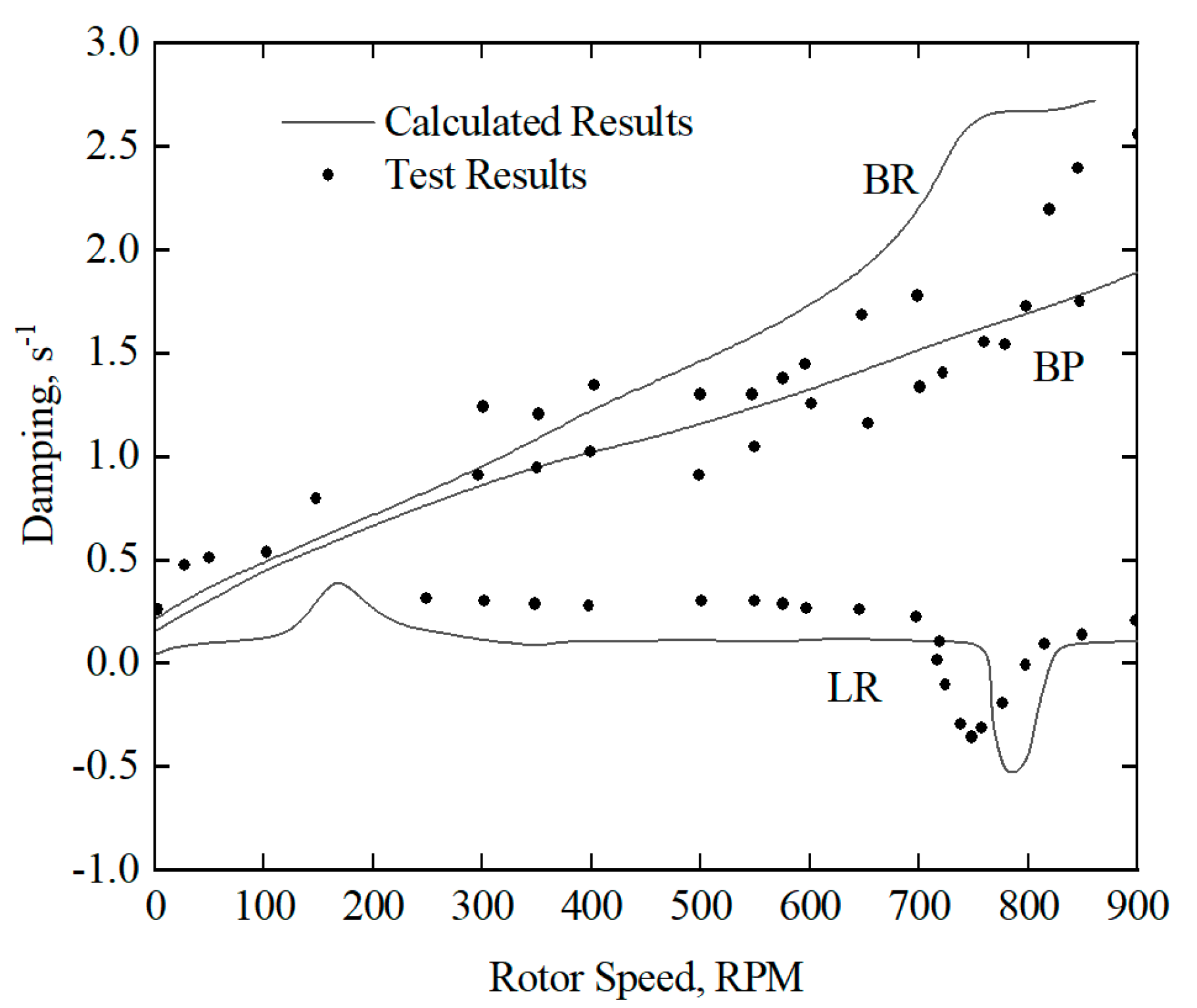
25] without taxiing is used to validate the analytical method used to calculate the aeromechanical stability. The modal frequencies and damping varying with rotational speed are shown in
Figure 5 and
Figure 6, respectively. In the figures, BP and BR, respectively, represent the pitching mode and the rolling mode of the fuselage. LA and LR, respectively, represent the progressive lag mode and the regressive lag mode of the rotor. FA and FR, respectively, represent the progressive flap mode and the regressive flap mode of the rotor. It can be seen from the figures that the calculated results agree with the test results, indicating that the analytical model and method for finding the aeromechanical dynamics of a helicopter without taxiing established in this paper is validated. When the rotational speed of the rotor reaches near 800 RPM, the frequency of the regressive lag mode of the rotor LR coalesces with the frequency of the rolling mode of the fuselage BR, resulting in an obvious decrease in the damping of the regressive lag mode of the rotor LR, and causing the ground resonance.
4. Aeromechanical Stability Analysis of Helicopter When Ground Taxiing
In this paper, the example of the Z-8 helicopter is used to analyze the aeromechanical stability of the helicopter when ground taxiing. The parameters of the Z-8 helicopter are listed in
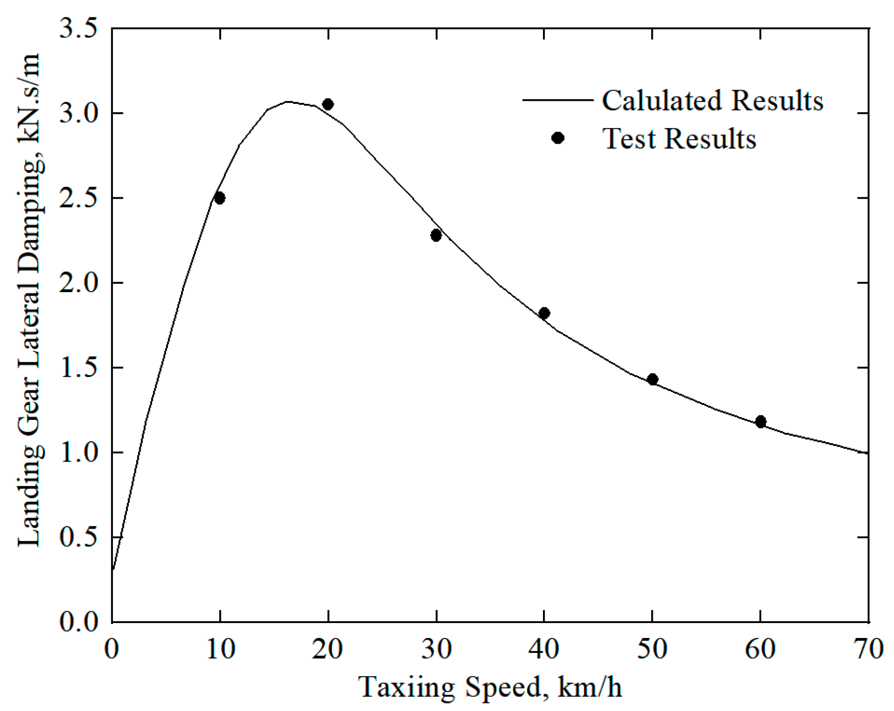
Table 1. The lateral mechanical characteristics of the landing gear wheel vary with the taxiing speeds. Hence, the lateral stiffness and damping of the Z-8 helicopter landing gear wheel, varying with different taxiing speeds, are calculated and shown in
Figure 7 and
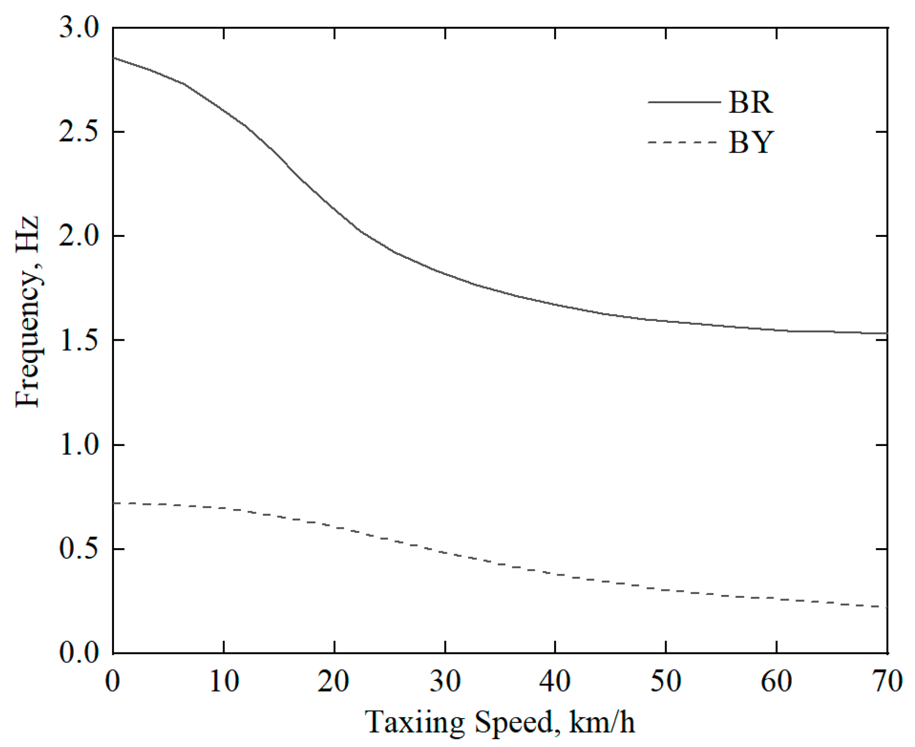
Figure 8. It can be seen from the figures that, with the increase in the taxiing speed, the lateral stiffness of the landing gear wheel decreases sharply, while the lateral damping of the landing gear wheel first increases sharply and then decreases fast. The frequencies of the lateral mode BY and the rolling mode BR of the fuselage, varying with the taxiing speed, are shown in
Figure 9. It can be seen from the figure that the frequencies of the BR mode and the BY mode of the fuselage decrease significantly with increasing taxiing speed, due to the decrease in the lateral stiffness of the landing gear wheel as taxiing speed increases.
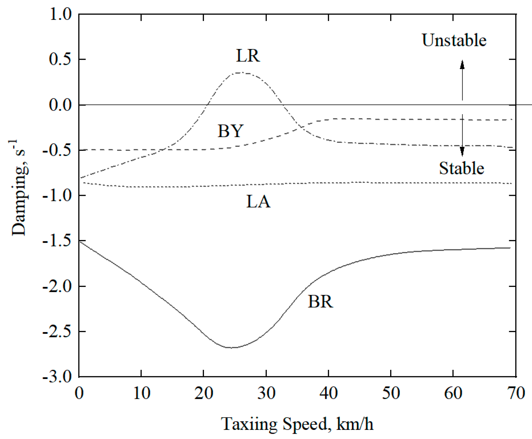
When the aerodynamic forces are not considered, the aeromechanical stabilities of the Z-8 helicopter at different taxiing speeds are analyzed, and the frequencies and damping of different modes varying with taxiing speeds are obtained, as shown in
Figure 10 and
Figure 11, respectively. It can be seen from the figures that, except for the rolling mode BR and lateral mode BY of the fuselage, which vary greatly with the increase in taxiing speed, the other modes are less affected by taxiing speed. When the taxiing speed reaches around 24 km/h, the frequencies of the regressive lag mode LR of the rotor and the rolling mode BR of the fuselage are close, which means the LR mode and BR mode are coupled, resulting in a significant decrease in the damping of the BR mode. When the taxiing speed is between 15 and 41 km/h, the system becomes unstable.
When the aerodynamic forces are considered, the rotor coupling trim analysis is first conducted to determine the pitch controls of the rotor at a given taxiing speed. Then, the frequencies and damping of different modes are calculated to analyze the aeromechanical stability. The calculated frequencies and damping of the different modes of the Z-8 helicopter rotor/fuselage coupling system after considering aerodynamic forces are shown in
Figure 12 and
Figure 13, respectively. It can be seen from the figures that when the aerodynamic forces are considered, the frequencies of the rolling mode BR and lateral mode BY of the fuselage still decrease sharply with the increase in the taxiing speed. The taxiing speed, when the frequency of the regressive lag mode LR of the rotor coalesces with the frequency of the rolling mode BR of the fuselage, increases to 30 km/h, and the range of unstable taxiing speeds decreases to 20–32 km/h.
Comparing
Figure 11 with
Figure 13, it can be seen that, after considering aerodynamic forces, the damping of all modes of the Z-8 helicopter when ground taxiing has increased, the critical unstable taxiing speed has increased, the range of unstable taxiing speeds has decreased, and the unstable region of the rotor/fuselage coupling system has also decreased. This is because the aerodynamic forces have direct influences on the coupling relations among the motions of the rotor and fuselage in all directions. The increase in the aerodynamic damping of the flapping and the lagging of the rotor produces influences on the modal damping of the rotor and fuselage in all directions, thereby improving the aeromechanical stability of the rotor/fuselage coupling system when ground taxiing. Therefore, when conducting the aeromechanical stability analysis of a helicopter that is ground taxiing, whether the aerodynamic forces are considered will have significant influences on the critical instability taxiing speed and the range of instability taxiing speeds that are calculated. In order to simulate the real state of ground taxiing, when modeling the rotor/body coupling system, it is not only necessary to consider the landing gear characteristics changing with the taxiing speed, but also to establish an accurate aerodynamic model, so as to reflect the changes in the damping of each mode with the taxiing speed. Furthermore, in addition to considering the rotor aerodynamic forces, the effects of ground vortex and crosswind influence should be taken into account when studying the aeromechanical stability of a helicopter that is ground taxiing.
