Article

Investigation on Aerodynamic Characteristics of Propeller–Wing Combination Configuration Under Heavy Rainfall

1
School of Aeronautics, Northwestern Polytechnical University, Xi’an 710072, China
2
Chinese Flight Test Establishment, Xi’an 710089, China
3
National Key Laboratory of Aircraft Configuration Design, Xi’an 710072, China
*
Author to whom correspondence should be addressed.
Aerospace 2025, 12(11), 975; https://doi.org/10.3390/aerospace12110975
Submission received: 29 August 2025 / Revised: 28 October 2025 / Accepted: 29 October 2025 / Published: 30 October 2025
(This article belongs to the Special Issue Advanced Aircraft Structural Design and Applications)

Abstract

This paper, based on the CFD-DPM model coupled with sliding grid technology, constructs a simulation analysis method for the aerodynamic effects of propellers and wings under heavy rainfall. The mechanism of the influence of raindrops on the aerodynamic characteristics of this configuration is deeply analyzed, and the influence of the laws of different rainfall parameters is explored. The conclusion indicates that the local attack angle of the propeller decreases due to the influence of the falling speed of raindrops, resulting in a decrease in blade thrust and a maximum loss of 2.35%. The torque increases due to the increase in the rotational drag of the propeller. The maximum torque increment reaches 2.15%. With a decrease in the local angle of the attack and the effects of raindrop impact, film covering, and splashing, the maximum lift loss is 1.84%, and the drag increases by more than 12%. Raindrops will further influence the pitching, rolling, and yawing moment variation effect, combined with the rotation of the propeller. The greater the terminal velocity, diameter, and rainfall are, close to the surface of the propeller–wing combination configuration, the more severe the deterioration of the blade performance, and the stronger the lift reduction, drag increase, and moment variation effects of the wing.

1. Introduction

Propeller-driven transport aircraft have unique advantages in terms of takeoff and landing sites and environmental adaptability, due to their excellent low-speed flight performance. Therefore, they have been widely applied in scenarios such as emergency rescue, general aviation transportation, and special operations [1,2,3,4,5,6]. However, as key power and aerodynamic components, the aerodynamic characteristics of the propellers and wings of this type of aircraft vary in different flight scenarios, especially under heavy rainfall conditions, where raindrops hit the propellers and wings, causing local water film coverage. Under the combined action of propeller rotation slip and flight speed, complex aerodynamic phenomena are formed, thereby affecting the flight efficiency of the aircraft [7,8,9,10,11,12]. Due to the severe impact of heavy rainfall on the aerodynamic characteristics of aircraft, multiple research institutions have carried out theoretical analysis, numerical simulations, and experiments on the aerodynamic characteristics of aircraft under rainfall conditions.
Thompson [13] analyzed wing aerodynamic efficiency in rainy conditions through computational fluid dynamics simulations, concluding that rain droplets significantly increase drag and reduce lift-to-drag ratios by disrupting airflow patterns. Wu [14,15] employed a two-way coupled Eulerian–Lagrangian approach to simulate rain effects on airfoils and wings, demonstrating that rain-induced droplet interactions degrade aerodynamic performance by increasing drag and altering boundary layer dynamics. Ismail [16,17] investigated the airfoil performance degradation in heavy rain conditions through experimental and computational methods, and the research revealed that rainfall significantly reduces lift-to-drag ratios by disrupting boundary layer flow and increasing surface roughness effects. Wan [18] analyzed the helicopter rotor blade aerodynamics in heavy rain with CFD, showing that rainfall drastically degrades performance by increasing drag, reducing lift, and altering flow separation patterns due to water film formation and droplet impacts. Gahlot [19] proposed numerical simulations to demonstrate that rainfall severely degrades airfoil and rotor aerodynamic performance by disrupting boundary layers, forming water films, and inducing premature flow separation, ultimately reducing lift and increasing drag. Hossein [20] numerically investigated how Gurney flaps mitigate airfoil performance degradation in rain/icing conditions by delaying flow separation and improving pressure recovery, though their effectiveness diminishes under severe surface contamination. Haines [21] quantified how heavy rain significantly increases aerodynamic drag (up to 30%) and reduces lift (15–20%) on landing aircraft by disrupting the boundary layer flow, with water accumulation on wings exacerbating performance degradation during critical approach phases.
From the literature review, there are currently many studies on the aerodynamic interference of propeller wings in clean air, revealing the equivalent changes in the wing flow field caused by acceleration and rotation, due to propeller slip. However, research has not yet been conducted to consider the aerodynamic influence of propeller–wing coupling configurations under heavy rainfall.
This paper takes a typical combination of propeller and wing shapes as the research object and, based on the CFD-DPM model, constructs a simulation analysis method for the aerodynamic effects of propellers and wings under heavy rainfall conditions, considering the influence of propeller slip flow. The force efficiency characteristics of the propeller and the lift-drag characteristics of the wing surface under gas–liquid two-phase flow are deeply studied. The change mechanism of the spatial flow field of the propeller blade and the wing surface, caused by the mixture of raindrops, is analyzed, providing support for the design optimization of turboprop aircraft in complex meteorological environments.

2. Preliminary Analysis of Aerodynamic Effects of Heavy Rainfall on Propeller–Wing Coupling Configuration

Under heavy rainfall conditions, a large number of raindrops strike the propeller and wing surfaces at a certain speed, forming different binding effects. For the propulsion of the propeller, the coverage area formed by the impact of raindrops is limited. Coupled with the centrifugal force generated by rotation and the influence of the material properties of the propeller, the possibility of raindrops forming water film is smaller than that of horizontally rotating rotors. Its main function is divided into two aspects. Firstly, the drag, Fd, generated by the impact of raindrops, which exhibits a significant hindering effect on the rotation of the propeller, causing an increase in propeller power. The second reason is that it has a certain falling velocity, Vrain, which changes the original dry air velocity. The actual combined velocity of the blade profile formed by superposition decreases to, Vrr, which also reduces the local angle of the attack of the blade. Therefore, the thrust force generated at the same rotational speed is smaller, as shown in Figure 1.
For the wings behind the propeller blades, the impact of heavy rainfall is different from that of the propeller blades. On the one hand, due to the stable coverage of water film on the flat wing surface, water accumulation areas can be formed. The water accumulation area essentially changes the boundary and range of the boundary layer, and also reduces the ability of the airflow attachment, making it easier to separate. On the other hand, due to the changes in the upwash speed, Vuwr = VuwVrain, and downwash speed, Vdwr = Vrain + Vdw, of the propeller slipstream, the influence of the slipstream on the wing surface is manifested as a decrease in upwash and an increase in downwash, resulting in a decrease in the lift behind the propeller, as shown in Figure 2.

3. Construction of Service Environment for Turboprop Engines Under Heavy Rainfall Conditions

From the previous analysis, it can be seen that under heavy rainfall conditions, the main influencing principle of the blade–wing coupling configuration comes from the local angle of attack changes caused by the downforce of the propeller due to the high-density raindrop airflow two-phase flow, as well as the changes in the local flow characteristics, formed by the water film covering the wing surface. This complex impact relationship requires further verification and analysis, through high-precision simulation methods. According to the national standard GB/T 28592-2012 «Grade of precipitation» [22], heavy rain refers to a 24 h rainfall of about 25.0–49.9 mm, with a typical raindrop diameter range of 1 mm–4 mm. The corresponding terminal speed varies according to the diameter of raindrops, and Table 1 shows the correlation. The values of the terminal velocities are derived from Best’s study [23]. Obviously, the larger the diameter of the raindrops, the greater the terminal velocity, and the phenomenon of raindrop fragmentation and blade film coating caused by the blade’s impact may be more pronounced. Additionally, it is necessary to consider the spatial distribution density of raindrops. According to the statistical results, the maximum spatial density of raindrops can reach 2000 to 5000/m3 under short-term heavy rainfall, and the dominant raindrop diameter can reach 2.5 to 4.0 mm. This paper uses an extreme case to analyze the impact of heavy rain on the aerodynamic characteristics of the rotor.
According to the actual rainfall pattern, the particle size distribution of raindrops should present a logarithmic normal distribution form. However, considering that the main purpose of this paper is to study the influence of a heavy rainfall environment on the aerodynamic characteristics of blade–wing coupling, the parameter requirements for actual rainfall effects are not high. Therefore, this paper simplifies the simulation by keeping the raindrop particle size consistent, with a diameter of 4 mm, and maintaining a terminal velocity of 9 m/s when the raindrop reaches the blade–wing configuration.
During the simulation, the aircraft remains stationary and the airflow flows through its shape at its original flight speed. At this point, the original rainfall conditions also need to be converted into relative velocity and applied to the simulation process, as shown in Figure 3. Therefore, in the simulation process, the speed of raindrops is added to the flight speed of the aircraft as the input condition for the speed in the simulation.

4. Aerodynamic Characteristic Analysis of Propeller Wing Combination Configuration Under Heavy Rainfall Conditions

4.1. Calculation Configuration and Simulation Methods

This paper selects AGARD’s propeller–wing combination model to analyze the aerodynamic characteristics under rainfall conditions. In 1987, FFA in Sweden conducted a series of propeller slipstream tests with propeller–wing combination configurations [24,25]. This configuration consists of an R243 propeller with a diameter of 0.64 m, a fuselage, and wings. The wing chord length is 0.5 m, the wingspan is 2 m, and it is a straight wing with a reference area of 1 m2. The experimental parameters are Reynolds number, Re = 1.7 × 10⁶; incoming Mach number, Ma = 0.15; propeller speed, n = 6650 RPM, i.e., speed, ω = 696.4 rad/s; rotation period, T = 0.009 s; and incoming angle of attack, 0 degrees.
The key to the aerodynamic force of this configuration lies in capturing the up-and-down wash effect of the slipstream on the wing. Moreover, as the propeller rotates, the aerodynamic force changes behind the wing are affected by the swept blade wake, which also exhibits certain fluctuations and exhibits unsteady characteristics. Therefore, this paper adopts an unsteady CFD simulation method based on sliding grids to evaluate the aerodynamic characteristics of propeller–wing combinations. We separated the rotating area of the propeller from the external stationary areas, such as the wings and propeller grains, through sliding grids, and transferred parameter differences through the interface between the dynamic and static domains [26,27,28,29,30,31]. The advantage of this method lies in the overall motion of the rotating area’s dynamic mesh, without any change in mesh quality, which can ensure good computational accuracy and efficiency. The structured mesh was generated by ICEM, and local encryption was carried out in the propeller slipstream area to improve the capture accuracy of wake effects, as shown in Figure 4. In addition, a boundary layer grid is generated near the object surface, and the height of the first layer grid is set at 1 × 10⁻⁶ c (where c is the average aerodynamic chord length of the wing), basically ensuring that in the object surface grid, y+ = 1. The computational mesh was generated with a total number of 4.2 million points in the stationary area and a number of 3.8 million points in the propeller dynamic area, as is shown in Figure 4.
The CFD numerical simulation in this study is based on the three-dimensional unsteady N-S equations, as primarily expressed in Equation (1):
Q t + · F F v = S
where Q = (ρ, ρu, ρv, ρw, ρE) represents the conservative variables, F denotes the inviscid convective flux, Fv signifies the viscous flux, and S stands for the source term.
The turbulence model adopts model k-ω SST [32,33,34], which has better adaptability to small and medium-sized separation. This model combines the advantages of model k-ε and model k-ω and has good adaptability to both internal and external flow fields. The k-ω SST turbulence model offers improved accuracy near walls and separation regions by combining the robustness of k-ω models with the enhanced blending capability of SST formulations, making it widely used in aerodynamics and industrial CFD simulations. Its core equation is as follows:
ρ k t + ρ u j k x j = P β * ρ ω k + x j [ μ + σ k μ t k x j ] ( ρ ω ) t + ( ρ u j ω ) x j = γ v t P β ρ ω 2 + x j [ ( μ + σ ω μ t ) ω x j ] + 2 ( 1 F 1 ) ρ σ ω 2 ω k x j ω x j
Since the simulation of rainfall conditions is required for the calculation and analysis of this paper, there exists a two-phase flow of water and oils in the actual environment. Therefore, a multiphase flow model needs to be adopted to simulate the influence of the relationship between water and gas. Although this paper simulates a heavy rainfall environment, the proportion of droplets in the atmosphere is relatively low and still in the form of discrete phases. Therefore, the multiphase flow model adopted is the Euler–Lagrange model. This model considers droplets to be Lagrangian particles and simulates the interaction between sparsely distributed raindrops and a continuous phase (air) [35,36,37,38,39]. The motion of particles in the discrete phase model is governed by Newton’s second law, as shown in Equation (3). The continuous phase is described by the N-S equations given in Equation (1). A two-way coupling approach is employed to account for the interaction between the two phases, in which the momentum from the discrete phase is transferred to the continuous phase through source terms, and the equations for both phases are solved iteratively. The primary motivation for adopting two-way coupling is that the present study focuses on heavy rainfall conditions, where droplet concentration is relatively high. This method enables a more accurate representation of the disturbance induced by raindrops on the airflow.
m p d u p d t = F
where mp is the particle mass, up is the particle velocity, and ΣF represents the sum of forces including drag, gravity, and pressure gradient.
Based on the Eulerian–Lagrangian framework, this CFD-DPM method is designed to simulate the motion and interaction of discrete particles (e.g., droplets, bubbles, or solid particles) within a continuous fluid phase. By tracking individual or grouped particles while coupling their trajectories with the surrounding flow field via drag, lift, and gravity forces, it enables applications such as spray drying, erosion prediction, and pollutant dispersion.
To validate the CFD-DPM method employed in this study, an available three-generation airway configuration with experimental data [40] has been used to simulate the deposition efficiencies of air/solid flow. The model represents a human bifurcating airway geometry, used to analyze the internal flow field and particle deposition. A gas–solid mixture velocity inlet is set at the inlet surface, while pressure outlet boundary conditions are applied on the outlets. Detailed geometric configuration, mixture gas properties, and boundary parameters are provided in Reference [40], and the simulation conditions in this study are consistent with those reported therein. Despite differences in mixed airflow types, the underlying principles are similar, making them suitable for algorithm validation. Figure 4c shows the measured and predicted deposition efficiencies, and a good agreement has been obtained, which indicates that the model can correctly present the mixed flow behavior.

4.2. Analysis of Aerodynamic Changes in Blade–Wing Configuration Under Heavy Rainfall Conditions

Firstly, the aerodynamic characteristics of the propeller–wing combination configuration under the initial rainfall environment parameters were determined. The initial heavy rainfall condition parameters are set as follows: raindrop diameter of 4 mm and falling speed of 9 m/s. The total flow rate is calculated at 45 kg/s.
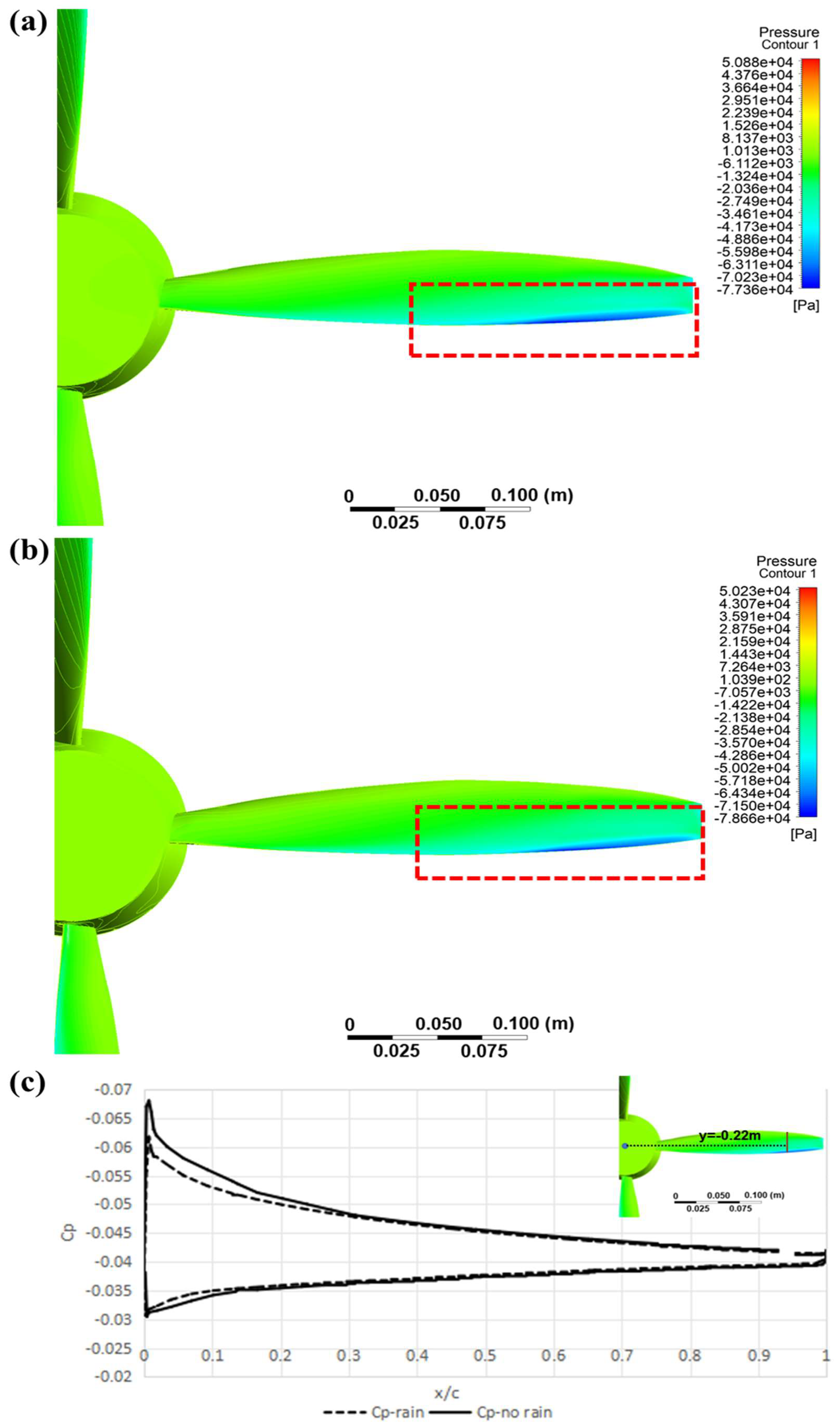
Figure 5 shows the comparison of the aerodynamic characteristics of propellers, with and without the influence of rainfall. To verify mesh independence under rainy conditions, this study evaluates simulation results using meshes with 0.5×, 1.5×, and 2× the resolution of the basic grid (comprising a total of 4.2 million cells in the stationary domain and 3.8 million cells in the propeller dynamic region). The differences in mesh density are primarily reflected in the boundary layer height, leading and trailing edges of the wing and blades, and the blade wake regions. The results show that coarsening the mesh leads to a maximum simulation error of 5.3%. In contrast, the results obtained with the 1.5× and 2× refined meshes agree well with those from the baseline mesh, with errors controlled within 5%. Therefore, the baseline mesh used in this study is considered to be sufficiently accurate. As shown in Figure 5, when working in rainy environments, the net thrust force generated decreases for propeller blades, and the propeller torque increases. The trend of change remains basically consistent with the increase in the angle of attack. Because the falling speed of raindrops causes additional velocity disturbances on the blades, the local blade section’s angle of attack decreases, thus having a significant impact on the thrust. Figure 6 shows the effect of rainfall on the pressure distribution on the blade surface. It can be clearly seen that the low-pressure area under rainfall conditions has a smaller range and intensity than in the no rainfall conditions. Figure 6c presents a comparison of the pressure coefficient at the blade spanwise section, y = −0.22 m. It can be observed that under rainy conditions, the magnitude of the low-pressure peak on the airfoil section is reduced, and its extent along the chordwise direction is also diminished. This results in a loss of local lift. Within the range of the angle of attack, the maximum thrust loss is 2.35%. Under rainy conditions, the propeller torque increases by a maximum of 2.15%, indicating that more kinetic energy is needed to generate thrust, resulting in an increase in power consumption.
In principle, the main source of torque generated by propellers is the drag of the blades, and the gas–liquid mixing drag caused by raindrops increases in both pressure difference and frictional drag. On the one hand, due to the possible coverage of water films on the surface of the blades, the local differential dissociation phenomenon inside the boundary layer is increased, resulting in an increase in pressure drag. On the other hand, the viscous effect between the water and propeller makes the frictional drag higher than that of the airflow. Overall, the research results of this paper indicate that under heavy rainfall conditions, the propeller thrust decreases and power consumption increases.
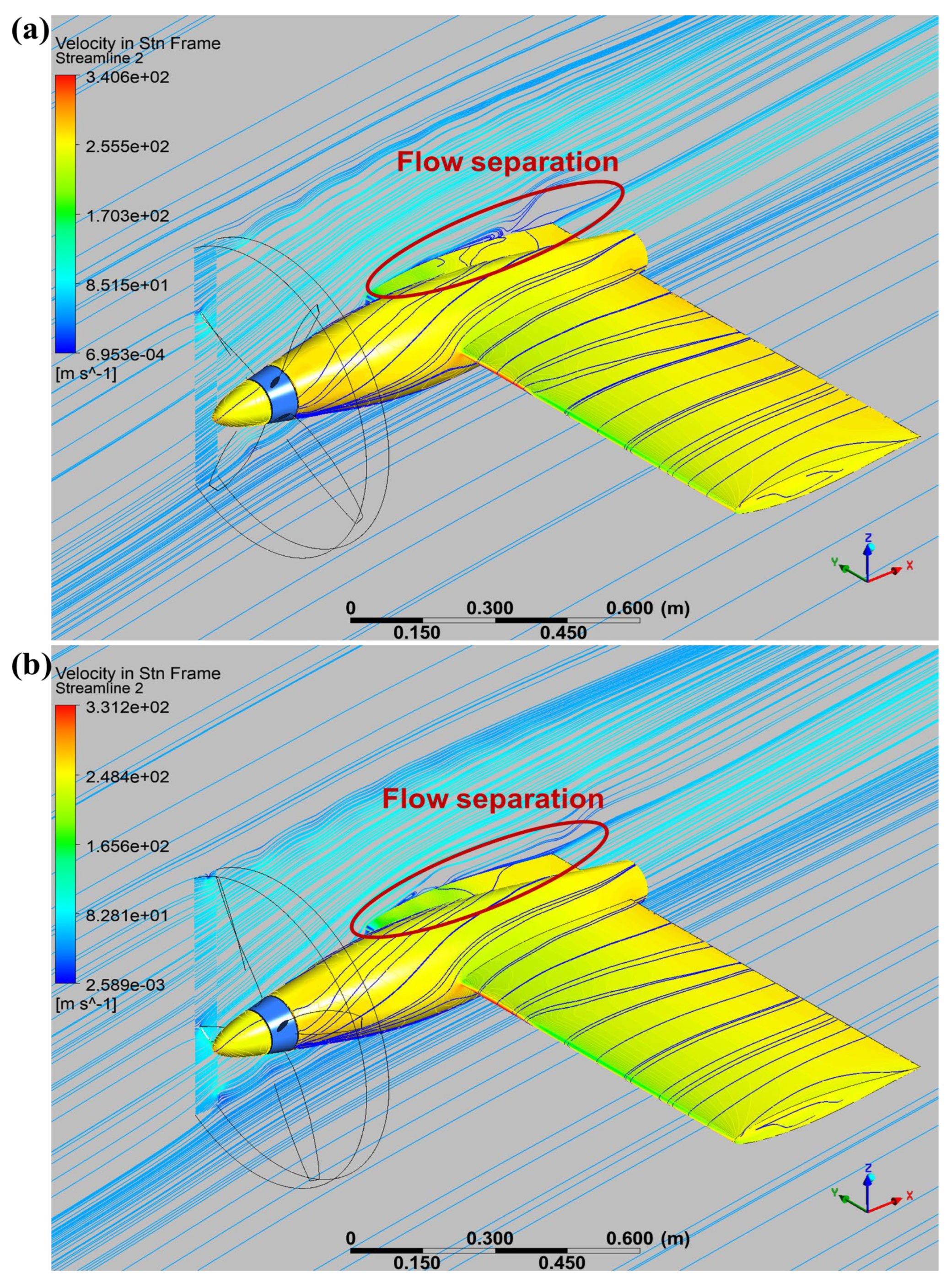
The aerodynamic characteristics of the rear wing of the propeller are shown in Figure 7. Similarly to the mechanism of blade thrust loss, the lift loss of the rear wing of the blade is actually due to the local descent speed, caused by the influence of raindrops mixed into the atmosphere. This speed is equivalent to reducing the original local angle of attack, resulting in local lift loss. Within the calculated angle of attack range, the maximum reduction in wing lift is 1.84%. In addition, when the angle of attack of the airflow is large, flow separation begins to occur on the upper wing surface of the wing. The flow separation on the upper wing surface under the same angle of attack in rainfall conditions is more pronounced than under clean air conditions, because the water film formed by the rain covering the wing surface changes the original local contour of the wing. However, the adhesion between gas and liquid is not as stable as that between gas and solid, thus promoting the occurrence of separation. Figure 8 shows the spatial separation with and without rainfall at a 10 degree angle of attack, which proves the conclusion that rainfall induces the flow field separation point to develop towards the leading edge of the wing and the separation range to expand. In terms of drag, the results at all angles of attack all indicate that rainfall can increase drag, and as the angle of attack increases, the increment of drag gradually increases, reaching a maximum of 12%. Similarly to propeller blades, the increase in drag under the influence of raindrops also comes from two aspects: pressure difference drag and frictional drag. In the case of small attack angles, the increase in drag is mainly the frictional drag caused by the attachment of raindrops, while in the case of large attack angles, the occurrence of local separation leads to a larger proportion of pressure difference in the drag increase.
The effect of rainfall on the pitch moment of the rear wing of the propeller is relatively small before an angle of attack of 6 degrees. However, when the angle of attack exceeds 6 degrees, the separation of the trailing edge of the wing leads to a loss of lift at the rear. At this time, the pitch moment of the wing under rainfall conditions is smaller than that under clean airflow conditions. The maximum difference in the pitch moment within the range of the calculated angle of attack between the two flight environments can reach 15%. The rolling torque is mainly caused by the lift imbalance phenomenon resulting from the up-and-down washing effect of the single blade rotation. In the case of a small attack angle, the impact of rainfall is relatively small. However, when the angle of attack increases to 10 degrees, raindrops will cause increased separation on the upstream side, thus resulting in lift loss on the upstream side and a decrease in the rolling torque caused by the rotation of a single blade. The influence of the heading characteristics of the body components where the propeller is located in the slipstream zone is mainly reflected in the vertical tail. In this paper, because there are only straight wings behind the propeller, the yaw moment is generated by the drag difference in the wings on both sides of the symmetry plane, and the result is relatively small. When the propeller wake, mixed with raindrops, causes up-and-down washing on the wings, the overall drag increases due to the increase in dynamic pressure, but the drag increments on both sides of the wings are different. The downwash of the wing by the descending blade is enhanced, resulting in greater lift loss and drag increases, while the upwash effect of the ascending blade is weakened, resulting in a decrease in drag. Therefore, the increase in drag difference leads to an increase in the wing yaw moment under rainy conditions. Compared to the no rainfall conditions, the yaw moment can increase by more than 400%.

4.3. Analysis of the Influence of Incoming Flow and Heavy Rainfall Parameters on the Aerodynamic Force of Propeller–Wing Combination

Through the simulation comparison in Section 4.2, it can be seen that under heavy rainfall conditions, the blade thrust loss, power consumption increase, lift–drag ratio of the wing decrease, and the torque characteristics also deteriorate, reflecting that rainfall has a relatively obvious impact on a propeller aircraft. This section conducts analysis and research on the impact of different environmental parameters, including the speed, diameter, and rainfall of raindrops.

4.3.1. The Influence of Raindrop Falling Speed

The falling speed of raindrops is not actually an isolated parameter, because rainfall occurs when water vapor condenses into droplets and falls under the action of gravity. At the same time, the falling process is affected by air drag, and the final falling speed at the end is also related to parameters such as the falling height, volume, and weight. This paper ignores this coupling relationship and only studies the influence of different raindrop falling velocities on the aerodynamic characteristics of the propeller–wing combination configuration, under the condition of a raindrop diameter of 4 mm and incoming flow angle of attack of 0 degrees, as shown in Figure 9.
When the falling speed of raindrops increases, the local additional velocity, generated by their impact on the object surface, also increases, which has a greater impact on the local attack angle of both propellers and wings. The thrust force of the propeller decreases with the increase in the falling speed of raindrops, while the torque increases with the increase in the falling speed. However, this relationship of change is not linear, mainly due to the correlation between the falling speed and the shape of the raindrops after hitting the surface. When the speed is low, the probability of raindrops forming a water film is higher, while when the speed is high, raindrops collide and produce various coupling effects, such as water film, splashing, and impact, making the disturbance of the flow field more complex.
The aerodynamic characteristics of the propeller trailing wing also exhibit nonlinear changes under different raindrop falling speeds. For the lift and drag of the wing, the greater the terminal velocity of raindrops, the more severe the phenomenon of reducing lift and increasing drag is. The rolling moment of the wing is manifested as a phenomenon where it suddenly increases and then changes smoothly as the speed of the raindrops increases. Because this article calculates an angle of attack of 0 degrees, neither the upper nor the lower washed wings have separated. However, due to the weakening of the up-washing process and the strengthening of the down-washing process, when the raindrop falling speed changes from 3 m/s to 4 m/s, the influential form of the raindrop–wing surface changes from film coating to multiple coupling effects, resulting in a slightly significant change in the rolling moment. However, overall, when the angle of attack is 0 degrees, there is not much difference in the rolling moment, and the pitching moment is also barely affected by the speed of raindrops falling. The relative change is more obvious in the yaw moment. As the terminal velocity of raindrops increases, the yaw effect caused by the imbalance of drag between the left and right wings due to blade interference becomes more pronounced. The greater the speed of the raindrops, the greater the impact energy they generate when hitting the aircraft body during flight. The difference in the up-and-down wash flow caused by the rotation of the propeller blades, combined with the speed of raindrops, expands the drag difference between the upper and lower sides of the propeller’s wings, resulting in this trend. Although the yaw moment magnitude of the wing itself is not large, the trend of the yaw effect changes exhibited can indicate the characteristics of the influence of raindrop velocity on propeller aircraft.

4.3.2. The Influence of Raindrop Diameter

The diameter of a raindrop determines its mass, which affects the energy of the raindrop impacting the propeller blades and wings, while keeping the end velocity constant. In this simulation, the falling speed of raindrops is set to 5 m/s and the angle of attack of the incoming flow is 0 degrees. Figure 10 shows the influence of raindrops of different diameters on the aerodynamic characteristics of propellers and the trailing propeller wing. Intuitively speaking, as the diameter of raindrops increases, the inertia of individual raindrops increases, and the local reaction force generated when they strike rotating components is also greater. Therefore, the power consumption required for the propeller to displace large-diameter raindrops during rotation is greater, which means that the torque of the blade itself increases as the diameter of the raindrops increases. From the simulation results in this paper, it can be seen that as the raindrop diameter increases from 1 mm to 4 mm, the propeller torque increases by 1%. Meanwhile, due to the increased drag caused by raindrops, the net thrust force of the propeller has also decreased by 0.92%.
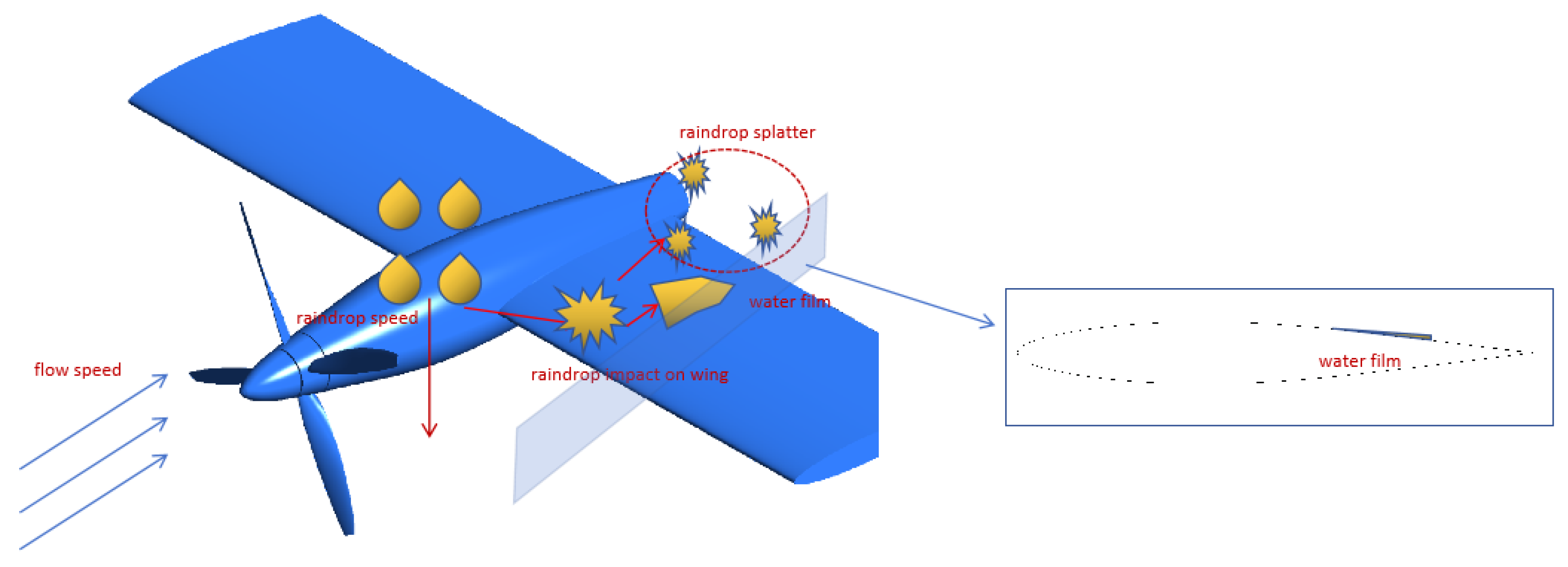
As the diameter of raindrops increases, the impact-film-splash effect formed on the wing surface becomes more complex, leading to a more complex mechanism of reduced lift and increased drag. The schematic diagram is shown in Figure 11. On the one hand, large diameter raindrops collide with the wing surface after being accelerated by the wake of the blade, and the fragmentation process transfers some of the kinetic energy to the wing, increasing its drag. On the other hand, the water film formed by the impact alters the original cross-sectional airfoil shape, causing an increase in friction, a decrease in pressure difference between the upper and lower surfaces, and a decrease in lift. Therefore, the larger the diameter, the more obvious the impact caused by raindrops.
The influence of the raindrop diameter on the rolling moment is relatively small, indicating that the main cause of this moment is still the lift difference caused by the up-and-down washing of the propeller. The influences of the yaw and the pitching moment are slightly greater. Due to the imbalance of drag between the left and right wings of the propeller, a yaw moment is generated. As the diameter of the raindrops increases, it further promotes this unbalanced drag, resulting in an increase in the yaw moment with the increase in the raindrop diameter. The pitching moment is due to the fact that at small angles of attack, the gas–liquid mixture flow thrown out by the propeller affects the lift distribution before and after. When large-diameter droplets hit the leading edge, they cause a film coating on the leading edge, increasing the head radius and causing the lift distribution to move forward. Therefore, there is a slight increase in the lift moment.

4.3.3. The Influence of Rainfall Amount

Whether it is the falling speed or the diameter of raindrops, they use a single parameter to describe changes in rainfall and cannot characterize the overall impact of rainfall. This section uses rainfall amount to measure the comprehensive impact of rainfall intensity. We define the amount of rainfall as the amount of rainwater flowing through the flow field per unit time. The diameter of the raindrops is set at 3 mm, the terminal velocity is 5 m/s, and the angle of attack of the incoming flow is 0 degrees.
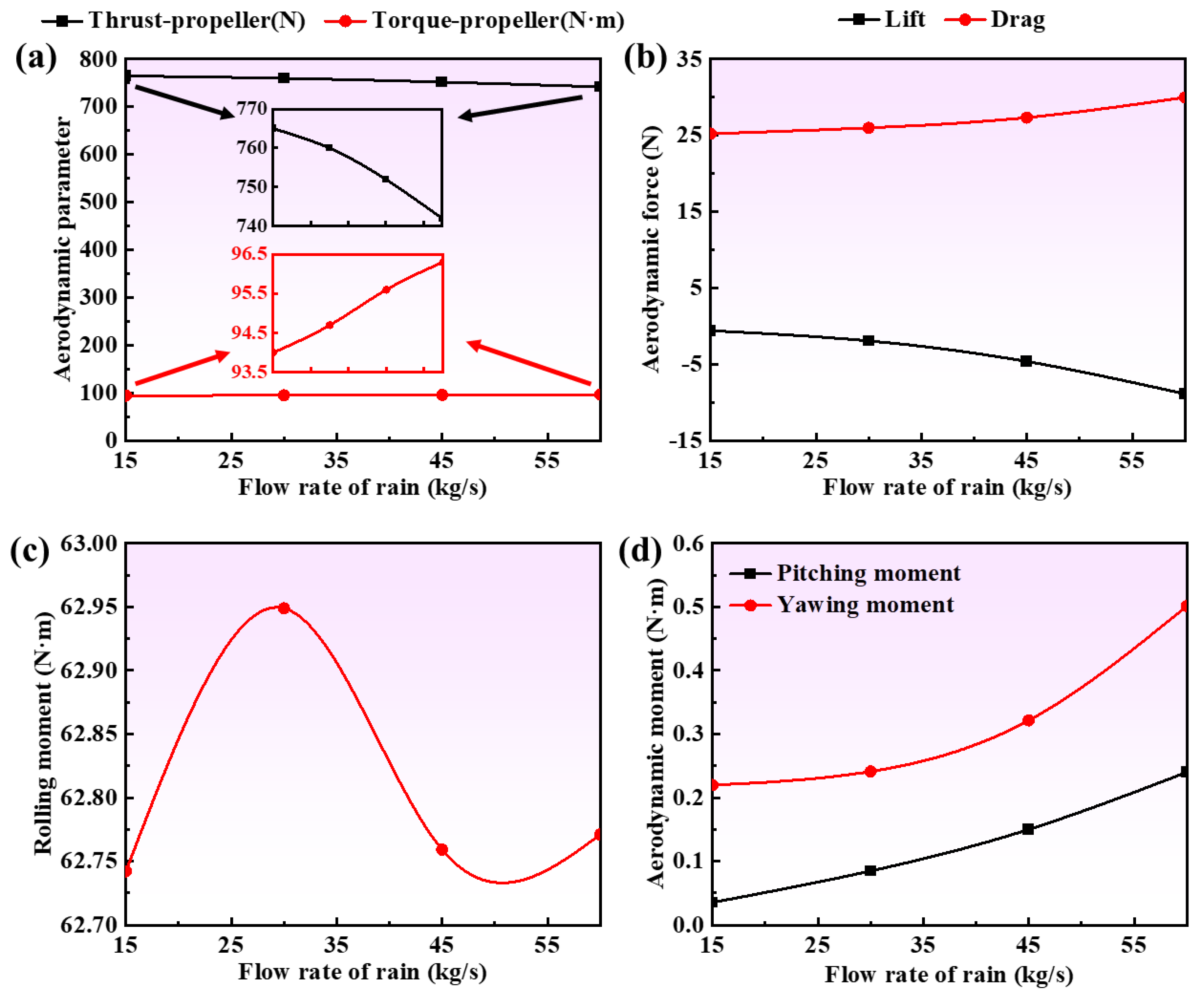
Figure 12 shows the aerodynamic characteristics of the blades and wings under rainfall, ranging from 15 to 60 kg/s. An increase in the rainfall amount indicates a greater number of raindrops per unit area, resulting in more impact on the blades and wings. This significantly increases the probability and intensity of phenomena such as the impact energy transfer, wing surface coating, and splashing. When the rainfall amount increased from 15 kg/s to 60 kg/s, the propeller’s thrust force lost 3% and the torque increased by 2.44%. The lift of the wing behind the propeller blades decreased from −0.6 to −8.9 N, and the drag increased by 18%. The fluctuation range of the rolling moment also increases accordingly, with the yaw moment increasing by 1.4 times and the pitching moment increasing by seven times. It can be seen from the results that after the rainfall intensifies, the interaction between raindrops and the aircraft body becomes stronger, and the aerodynamic characteristics of the propeller–wing combination configuration change become more complex. But it is clear that heavy rainfall will cause an increase in propeller power consumption and a decrease in thrust force. The wing behind the propeller reduces lift and increases drag, resulting in a more noticeable change in drag. The yaw and pitching moment changes in the wing are more severe than the rolling moment.

5. Conclusions

This paper, based on the coupling method of DPM+CFD, conducts an evaluation and analysis of the aerodynamic characteristics of the typical propeller–wing combination under rainfall conditions. The influence of different rainfall parameters on the aerodynamic characteristics of the propeller–wing combination configuration is also analyzed. The conclusions are as follows:
(1)
Raindrops hitting the blade reduce the local angle of attack, causing a decrease in its thrust force. Additionally, the kinetic energy of raindrops hitting the blade becomes drag, further affecting the net thrust force of the blade, resulting in a thrust force loss of up to 2.35%. Because the propeller rotates and collides with the gas–liquid mixture flow, more drag is generated during the blade rotation process, thus increasing the torque and power consumption. The maximum torque increment can reach 2.15%.
(2)
The impact of the mechanism of rainfall on the aft wing of the propeller is more complex. Firstly, it manifests as a decrease in lift and an increase in drag, with lift loss reaching 1.84% and drag increase reaching 12%. The main reason is that the coverage of the water film causes changes in the local shape of the cross-section, coupled with a decrease in the local angle of attack due to the speed of raindrops falling, resulting in a decrease in lift. The drag is composed of impact drag and pressure difference drag, caused by the easy separation of the rain film. The impact on the wing moment is relatively small, but it will enhance the yaw and rolling moment characteristics caused by the up-and-down washing of the propeller.
(3)
The greater the speed of raindrops falling, the larger the diameter of raindrops; the greater the amount of rainfall, the more it will cause a decrease in blade thrust, an increase in torque, and a further strengthening of the phenomenon of wing lift reduction, drag increase, and yaw and pitching moment increase. This reflects that under heavy rainfall conditions, the multiphase flow pattern of the airflow mixed with raindrops interferes with the mechanism of aerodynamic efficiency of the propeller blades, resulting in a deterioration of performance.

Author Contributions

Conceptualization, L.X. and J.Y.; methodology, L.X.; software, J.Y.; validation, L.X.; investigation, J.Y.; resources, H.H.; writing—original draft preparation, L.X.; writing—review and editing, Y.Z. and M.Z.; visualization, Y.Z.; supervision, H.H.; project administration, H.H.; funding acquisition, H.H. All authors have read and agreed to the published version of the manuscript.

Funding

This research was funded by the National Natural Science Foundation of China [grant number 12141203], the Fundamental Research Funds for the Central Universities [grant number D5000230052], the Shaanxi Innovation Ability Support Plan Project Funds [grant number 2024RS-CXTD-29], the Northwestern Polytechnical University Doctoral Dissertation Innovation Foundation [grant number CX2025100], the Practice and Innovation Funds for Graduate Students of Northwestern Polytechnical University [grant number PF2025024], the Young Elite Scientists Sponsorship Program by CAST [grant number 156-O-430-0000867-9], and the Key R&D Project in Shaanxi Province [grant number 2024GX-YBXM-263].

Data Availability Statement

The original contributions presented in this study are included in the article. Further inquiries can be directed to the corresponding author(s).

Acknowledgments

This work was supported by Northwestern Polytechnical University and the Chinese Flight Test Establishment.

Conflicts of Interest

The authors declare no conflicts of interest.

Abbreviations

The following abbreviations are used in this manuscript:
CFDComputational Fluid Dynamics
DPMDiscrete Phase Model

References

  1. Della Vecchia, P.; Nicolosi, F. Aerodynamic guidelines in the design and optimization of new regional turboprop aircraft. Aerosp. Sci. Technol. 2014, 38, 88–104. [Google Scholar] [CrossRef]
  2. Hu, Y.H.; Yan, J.Q.; Cao, E.T.; Yu, Y.M.; Tian, H.M.; Huang, H.Y. Approach and Landing Energy Prediction Based on a Long Short-Term Memory Model. Aerospace 2024, 11, 226. [Google Scholar] [CrossRef]
  3. Iwaniuk, A.; Wisniowski, W.; Zóltak, J. Multi-disciplinary optimisation approach for a light turboprop aircraft-engine integration and improvement. Aircr. Eng. Aerosp. Technol. 2016, 88, 348–355. [Google Scholar] [CrossRef]
  4. Jiang, Z.; Chen, Y.S.; An, Y.R.; Wang, Q.F. New actuator disk model for propeller-aircraft computation. Sci. China-Technol. Sci. 2016, 59, 1201–1207. [Google Scholar] [CrossRef]
  5. Simmons, B.M.; Gresham, J.L.; Woolsey, C.A. Aero-Propulsive Modeling for Propeller Aircraft Using Flight Data. J. Aircr. 2023, 60, 81–96. [Google Scholar] [CrossRef]
  6. Williams, A.; Marcotte, D. Wind measurements on a maneuvering twin-engine turboprop aircraft accounting for flow distortion. J. Atmos. Ocean. Technol. 2000, 17, 795–810. [Google Scholar] [CrossRef]
  7. Ashenden, R.; Marwitz, J.D. Turboprop aircraft performance response to various environmental conditions. J. Aircr. 1997, 34, 278–287. [Google Scholar] [CrossRef]
  8. Chauhan, S.S.; Martins, J. RANS-Based Aerodynamic Shape Optimization of a Wing Considering Propeller-Wing Interaction. J. Aircr. 2021, 58, 497–513. [Google Scholar] [CrossRef]
  9. Li, X.; Li, C.; Gao, J.; Li, S. Propeller slipstream effect on longitudinal aerodynamic characteristics of airplane. J. Exp. Fluid Mech. 2017, 31, 46. [Google Scholar]
  10. Mi, B.G.; Huang, H.Y. Intake grille design for an embedded ventilation-and-cooling system in an aircraft. Proc. Inst. Mech. Eng. Part G J. Aerosp. Eng. 2022, 236, 2352–2365. [Google Scholar] [CrossRef]
  11. Phillips, E.H. FAA to ban turboprops in freezing rain, drizzle. Aviat. Week Space Technol. 1996, 144, 36–37. [Google Scholar]
  12. Zhao, S.; Li, J.; Jiang, Y.X.; Qian, R.Z.; Xu, R.F. Investigation of propeller slipstream effects on lateral and directional static stability of transport aircraft. Eng. Appl. Comp. Fluid Mech. 2022, 16, 551–569. [Google Scholar] [CrossRef]
  13. Thompson, B.E.; Jang, J.H. Aerodynamic efficiency of wings in rain. J. Aircr. 1996, 33, 1047–1053. [Google Scholar] [CrossRef]
  14. Wu, Z.; Cao, Y. Aerodynamic study of aerofoil and wing in simulated rain environment via a two-way coupled Eulerian-Lagrangian approach. Aeronaut. J. 2014, 118, 643–668. [Google Scholar] [CrossRef]
  15. Wu, Z.L.; Cao, Y.H.; Ismail, M. Numerical Simulation of Airfoil Aerodynamic Penalties and Mechanisms in Heavy Rain. Int. J. Aerosp. Eng. 2013, 2013, 13. [Google Scholar] [CrossRef]
  16. Ismail, M.; Cao, Y.H. Airfoils Aerodynamic Performance Analysis in Heavy Rain. Appl. Mech. Mater. 2012, 245, 297–302. [Google Scholar] [CrossRef]
  17. Ismail, M.; Umer, U. Aerodynamic Efficiency Study of GLC-305 Airfoil in Simulated Rain and Icing Conditions. In International Conference on Control Engineering and Mechanical Design (CEMD 2017); Li, C., Ed.; ASME Press: New York, NY, USA, 2018; p. 324. [Google Scholar]
  18. Wan, T.; Lin, J.-X.; Kuan, H.-C. Aerodynamic analysis of helicopter rotor blades in heavy rain condition. In Proceedings of the 51st AIAA Aerospace Sciences Meeting including the New Horizons Forum and Aerospace Exposition 2013, Grapevine, TX, USA, 7–10 January 2013; American Institute for Aeronautics and Astronautics (AIAA): Reston, VA, USA, 2013. [Google Scholar]
  19. Gahlot, A.S.; Eshcol, R.M.; Sankar, L.N.; Kreeger, R.E. Numerical Simulations of the Adverse Effects of Rain on Airfoil and Rotor Aerodynamic Characteristics. J. Am. Helicopter Soc. 2023, 68, 9. [Google Scholar] [CrossRef]
  20. Fatahian, H.; Salarian, H.; Nimvari, M.E.; Khaleghinia, J. Effect of Gurney flap on flow separation and aerodynamic performance of an airfoil under rain and icing conditions. Acta Mech. Sin. 2020, 36, 659–677. [Google Scholar] [CrossRef]
  21. Haines, P.; Luers, J. Aerodynamic penalties of heavy rain on landing airplanes. J. Aircr. 1983, 20, 111–119. [Google Scholar] [CrossRef]
  22. GB/T 28592-2012; Grade of Precipitation. China Meteorological Administration: Beijing, China, 2012.
  23. Foote, G.B.; Du Toit, P.S. Terminal Velocity of Raindrops Aloft. J. Appl. Meteorol. Climatol. 1969, 8, 249–253. [Google Scholar] [CrossRef]
  24. Trebble, W.J.G. Investigations of the aerodynamic performance and noise characteristics of a Dowty Rotol R212 propeller at full-scale in the 24 ft wind tunnel. Aeronaut. J. 1987, 91, 275–284. [Google Scholar] [CrossRef]
  25. Zhou, Q.; Joseph, P.F. Frequency-domain method for rotor self-noise prediction. AIAA J. 2006, 44, 1197–1206. [Google Scholar] [CrossRef]
  26. Benini, E.; Toffolo, A. Innovative procedure to minimize multi-row compressor blade dynamic loading using rotor-stator interaction optimization. Proc. Inst. Mech. Eng. Part A J. Power Energy 2007, 221, 59–66. [Google Scholar] [CrossRef]
  27. McNaughton, J.; Afgan, I.; Apsley, D.D.; Rolfo, S.; Stallard, T.; Stansby, P.K. A simple sliding-mesh interface procedure and its application to the CFD simulation of a tidal-stream turbine. Int. J. Numer. Methods Fluids 2014, 74, 250–269. [Google Scholar] [CrossRef]
  28. Nam, H.J.; Park, Y.M.; Kwon, O.J. Simulation of unsteady rotor-fuselage aerodynamic interaction using unstructured adaptive meshes. J. Am. Helicopter Soc. 2006, 51, 141–149. [Google Scholar] [CrossRef]
  29. Park, Y.M.; Kwon, O.J. Simulation of unsteady rotor flow field using unstructured adaptive sliding meshes. J. Am. Helicopter Soc. 2004, 49, 391–400. [Google Scholar] [CrossRef]
  30. Steijl, R.; Barakos, G. Sliding, mesh algorithm for CFD analysis of helicopter rotor-fuselage aerodynamics. Int. J. Numer. Methods Fluids 2008, 58, 527–549. [Google Scholar] [CrossRef]
  31. Xu, H.Y.; Xing, S.L.; Ye, Z.Y.; Ma, M.S. A simple and conservative unstructured sliding-mesh approach for rotor-fuselage aerodynamic interaction simulation. Proc. Inst. Mech. Eng. Part G J. Aerosp. Eng. 2017, 231, 163–179. [Google Scholar] [CrossRef]
  32. Chitsomboon, T.; Thumthae, C. Adjustment of k-w SST Turbulence Model for an Improved Prediction of Stalls on Wind Turbine Blades. In Proceedings of the World Renewable Energy Congress, Linköping, Sweden, 8–13 May 2011. [Google Scholar] [CrossRef]
  33. Halder, P.; Rhee, S.H.; Samad, A. Numerical optimization of Wells turbine for wave energy extraction. Int. J. Nav. Archit. Ocean Eng. 2017, 9, 11–24. [Google Scholar] [CrossRef]
  34. Li, X.L.; Zhu, H.R.; Liu, C.L.; Ye, L.; Xu, Z.P.; Li, G.D.; Xu, W.J. Research on enhancing impingement structure heat transfer capability based on secondary impingement. Int. J. Therm. Sci. 2025, 211, 14. [Google Scholar] [CrossRef]
  35. Cai, P.; Nie, W.; Chen, D.W.; Yang, S.B.; Liu, Z.Q. Effect of air flowrate on pollutant dispersion pattern of coal dust particles at fully mechanized mining face based on numerical simulation. Fuel 2019, 239, 623–635. [Google Scholar] [CrossRef]
  36. Cheng, W.; Jia, B.; Dong, Z.C.; Wu, Z.Y.; Zhao, X.; Wan, X.P.; Liu, Z.; Huang, H.Y. Computational paradigm for Mg-Li alloy innovation: Decoding atomic doping mechanisms for targeted property enhancement. Results Eng. 2025, 27, 24. [Google Scholar] [CrossRef]
  37. Heald, J.; McEwan, I.; Tait, S. Sediment transport over a flat bed in a unidirectional flow: Simulations and validation. Philos. Trans. R. Soc. Lond. Ser. A-Math. Phys. Eng. Sci. 2004, 362, 1973–1986. [Google Scholar] [CrossRef] [PubMed]
  38. Peters, B. Measurements and application of a discrete particle model (DPM) to simulate combustion of a packed bed of individual fuel particles. Combust. Flame 2002, 131, 132–146. [Google Scholar] [CrossRef]
  39. Rashidi, S.; Esfahani, J.A.; Ellahi, R. Convective Heat Transfer and Particle Motion in an Obstructed Duct with Two Side by Side Obstacles by Means of DPM Model. Appl. Sci. 2017, 7, 431. [Google Scholar] [CrossRef]
  40. Chen, X.L.; Zhong, W.Q.; Sun, B.B.; Jin, B.S.; Zhou, X.G. Study on gas/solid flow in an obstructed pulmonary airway with transient flow based on CFD-DPM approach. Powder Technol. 2012, 217, 252–260. [Google Scholar] [CrossRef]
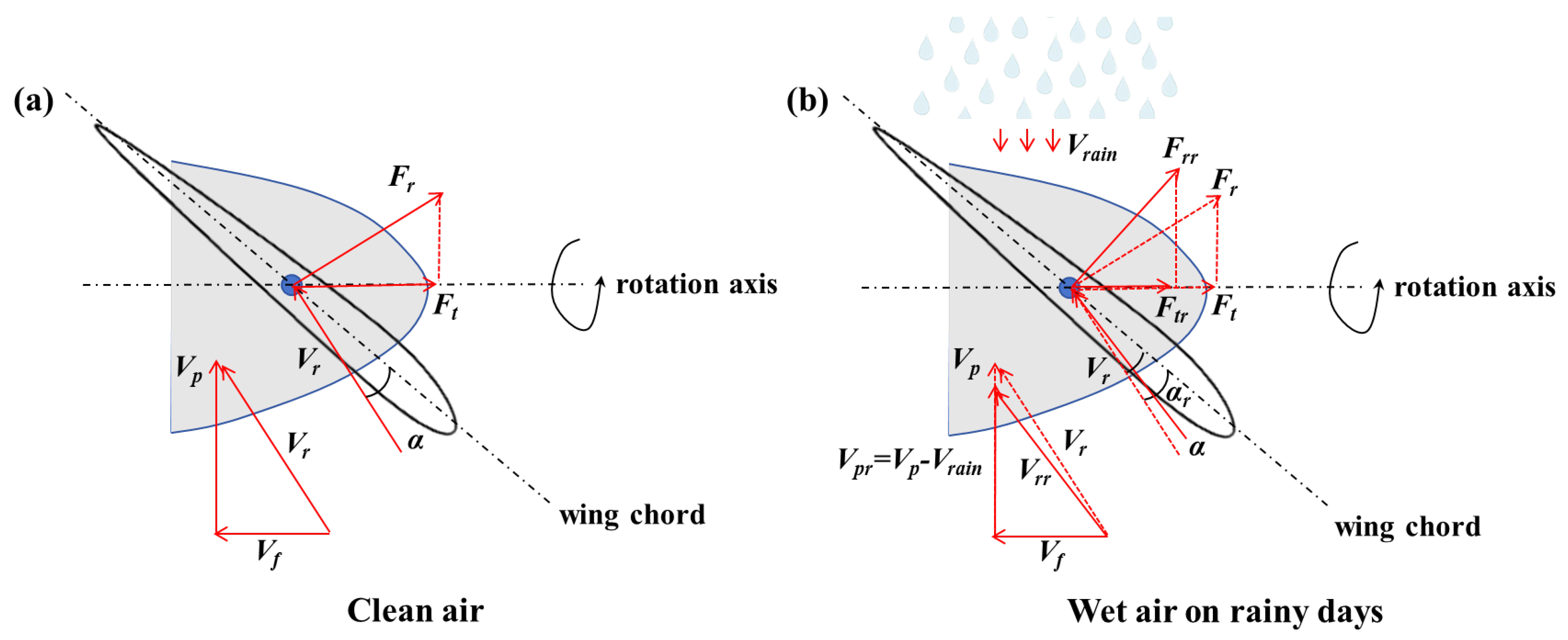
Figure 1. Schematic diagram of speed characteristics of propellers under different air conditions. (a) Clean air; (b) wet air under heavy rainfall conditions.
Aerospace 12 00975 g001
Figure 2. The variation in velocity characteristics of a propeller wing under different air conditions. (a) Clean air; (b) wet air under heavy rainfall conditions.
Aerospace 12 00975 g002
Figure 3. The conversion of rainfall condition parameters in the simulation.
Aerospace 12 00975 g003
Figure 4. Unsteady simulation grid. (a) Wing rotor and interface mesh; (b) propeller mesh. (c) CFD-DPM method validation on three-generation airway configuration.
Aerospace 12 00975 g004
Figure 5. Aerodynamic performance of propeller. (a) Thrust; (b) torque.
Aerospace 12 00975 g005
Figure 6. The pressure distribution on the surface of propeller blades under the influence of rainfall. (a) No rain condition; (b) rainfall condition; (c) Cp plots at y = −0.22 m section.
Aerospace 12 00975 g006
Figure 7. Aerodynamic performance of wings. (a) Lift; (b) drag; (c) pitching moment; (d) rolling moment; (e) yawing moment.
Aerospace 12 00975 g007
Figure 8. Comparison of wing airflow separation at 10 degree angle of attack. (a) No rainfall conditions; (b) rainfall conditions.
Aerospace 12 00975 g008
Figure 9. The influence of the raindrop falling velocity on the aerodynamic characteristics of blade wings. (a) Propeller thrust and torque; (b) lift and drag of wings; (c) rolling moment of wings; (d) pitching and yaw moments of the wing.
Aerospace 12 00975 g009
Figure 10. The influence of the raindrop diameter on the aerodynamic characteristics of blade wings. (a) Propeller thrust and torque; (b) lift and drag of wings; (c) rolling moment of wings; (d) pitching and yaw moments of the wing.
Aerospace 12 00975 g010
Figure 11. Diagram of large diameter raindrops hitting wings.
Aerospace 12 00975 g011
Figure 12. The influence of rainfall amount on the aerodynamic characteristics of blade wings. (a) Propeller thrust and torque; (b) lift and drag of wings; (c) rolling moment of wings; (d) pitching and yaw moments of the wing.
Aerospace 12 00975 g012
Table 1. The relationship between raindrop diameter and terminal velocity.
Raindrop Diameter (mm)Terminal Velocity (m/s)
13.0–4.0
25.0–6.5
37.0–8.0
48.0–9.0
Disclaimer/Publisher’s Note: The statements, opinions and data contained in all publications are solely those of the individual author(s) and contributor(s) and not of MDPI and/or the editor(s). MDPI and/or the editor(s) disclaim responsibility for any injury to people or property resulting from any ideas, methods, instructions or products referred to in the content.