Article

Research on the Cooling Characteristics of the Circular Ring Structure of Aircraft Engine Endoscope Probes

by
Hao Zeng
1,2,
Rui Xi
1,
Jingbo Peng
1,*,
Lu Jia
1 and
Changqin Fu
1
1
Air Force Engineering University, Xi’an 710038, China
2
Xi’an Jiaotong University, Xi’an 710049, China
*
Author to whom correspondence should be addressed.
Aerospace 2025, 12(11), 962; https://doi.org/10.3390/aerospace12110962 (registering DOI)
Submission received: 8 September 2025 / Revised: 9 October 2025 / Accepted: 22 October 2025 / Published: 28 October 2025
(This article belongs to the Section Aeronautics)

Abstract

Aircraft engine endoscope probes often face difficulties in effectively detecting internal structures in high-temperature environments. In order to improve the thermal protection characteristics of endoscope probes, this paper designs a probe-cooling structure with a circular ring pressure drop structure and calculates and analyzes the cooling effect of the probe under different gas cooling conditions. Study the influence of size parameters and cooling medium properties of the structure on the cooling characteristics of the probe, analyze the temperature distribution of the probe mirror, cooling efficiency distribution, and cold flow outlet flow distribution. The results show that the larger the outlet width of the annular cooling structure, the better the cooling effect, and the optimal cooling effect structure is 0.7 mm; the larger the opening angle, the lower and then the higher the temperature of the endoscope probe surface, and the best cooling effect occurs when the optimal angle is 40°; the larger the proportion of mixed liquid nitrogen, the lower the temperature of the probe mirror surface. A 5% proportion of mixed liquid nitrogen can reduce the temperature of the probe mirror surface by about 11 K.

1. Introduction

Aircraft engines have complex structures and extremely high precision, serving as the power source for the aircraft. The working condition of aircraft engines is closely related to the safety of the aircraft. The inspection of the engine airflow channel is to check the safety of the aircraft. Turbine blades are key hot end components of aircraft engines, and their manufacturing process directly affects the various efficiencies of aircraft engines, earning them the title of the heart of aircraft engines [1]. Turbine blades are key components of aircraft engine power systems, and their manufacturing technology directly affects the performance of aircraft engines [2]. At present, the thrust-to-weight ratio of engines is constantly increasing. In the future, the turbine inlet temperature of the fifth generation aircraft engine with an extremely high thrust-to-weight ratio will exceed 2000 K. The high temperature of aircraft engines urgently needs to be solved by scientists [3,4]. Turbine blades are also prone to damage when the temperature is too high, causing serious and irreversible consequences [5]. Turbine blades should be developed toward high temperature resistance, long lifespan, and low cost. The cooling technology of turbine blades has been widely applied by researchers and can effectively cope with high temperatures inside the engine [6]. Through phase-change medium cooling technology, the wall temperature of high-temperature components in aircraft engines can be effectively reduced, thereby improving thermal protection performance [7].
Turbine blades are prone to damage after prolonged exposure to high temperatures, and aircraft engines cannot do without turbine blade cooling technology. As the inclination angle of the gas film hole increases within a certain range, the cooling efficiency of the turbine blade first increases, and then decreases, indicating that the cooling efficiency is related to the penetration ability and area characteristics of the jet [8]. Chen et al. [9] found that the position of the gas film holes under supersonic conditions has a significant impact on the flow field distribution in the blade cascade channel, and the gas film jet with upstream openings can transfer energy to the blade boundary layer. Li et al. [10] designed a method for arranging gas film holes on the end wall of turbine blades, optimizing multiple parameters simultaneously. The cooling efficiency of the end wall gas film was improved by 68%, and the total pressure loss was reduced by 10%.
At present, although the factory has developed the initial high-temperature resistant hole probes, the existing hole probe technology is not mature at high temperatures, and researchers have conducted relatively little research. At present, most designs use cooling protective sleeves for hole probes to form air film cooling and improve the thermal protection performance of hole probes. Li et al. [11] found that the number and diameter of gas film holes directly affect the degree of gas film coverage at the bottom of the probe protective cover, and the highest temperature of the protective cover showed a trend of first decreasing and then increasing after cooling with cooling air. Ye et al. [12] designed a protective structure for infrared temperature probes and found that when the total pressure at the air inlet was low, gas could not be sent out of the endoscope. The higher the total pressure at the air inlet, the smoother the change in the highest temperature of the probe.
Zhang et al. [13] used nitrogen as a cooling medium and found that increasing the blowing ratio or pore size in a circular straight pipe can significantly improve the film cooling efficiency. Xue et al. [14] designed various film cooling structures and found that the cooling effect was more uniform when there were more seam rows, and the temperature reduction effect on the cooling section was significant. Zhang et al. [15] calculated and compared the cooling effects of different film cooling structures on the expansion regulating plate of the tail nozzle of an aircraft engine. They found that slot film cooling and discrete small hole film cooling had cooling effects on both the upstream and downstream of the film, resulting in a uniform temperature distribution on the nozzle wall.
The pressure reduction number is a key parameter for reducing fluid pressure in pressure drop structures, and the larger the pressure reduction stage, the greater the increase in fluid pressure drop [16]. Zhai et al. [17] studied the variation laws of different coolant inlet velocities and temperatures and found that increasing the number of outlet holes can effectively reduce pressure and that increasing the cold flow rate or reducing the coolant inlet temperature can improve cooling characteristics. P. B. et al. [18] studied the relationship between the flow rate of the sprinkler and the size and pressure distribution of each channel. The calculated diameter was minimized, and the sprinkler was divided into multiple stages to achieve step-by-step pressure reduction. Wang et al. [19] studied the pressure characteristics of multi-stage pressure-reducing orifice tubes and found that reducing the diameter of the orifice plate of a specific grade can increase the pressure drop. Under the condition of constant flow rate, the size and arrangement of the multi-stage orifice plate are crucial for actual pressure reduction in engineering.
In the daily maintenance and inspection of aircraft engines, technicians mainly rely on industrial endoscope technology to conduct detailed inspections of internal components of the engine. This efficient detection method can quickly identify and accurately locate potential damage inside the engine. Zhang et al. [20] conducted experiments and simulations on a certain micro optical window, analyzing the effects of different hole types and other parameters on cooling efficiency, flow rate, and pressure drop. Xie et al. [21] set a protective cover for the endoscope probe to ensure the accuracy of the detection process while ensuring damage. High-temperature environments can easily damage the working area where the probe end camera is located, so measures should be taken to effectively prevent it [22]. The hole detector is prone to high-temperature damage, and the hot end components should be strictly inspected. Both the engine and the hole detector should be cooled and protected within the specified time [23]. Sun [24] conducted research on industrial endoscope inspection technology and found that it can not only monitor internal faults of engines but also determine the location of damage based on relevant experience and standards with clear detection images.
Currently, research on gas cooling methods mostly focuses on the influence of cooling methods and structural parameters on cooling effectiveness; currently, research in the field of liquid cooling mainly focuses on parameters such as flow rate, temperature, and pressure of liquid media. However, these studies are still incomplete in terms of probe structure design and cooling medium characteristic parameters. Therefore, this article will conduct a more in-depth exploration of the cooling effect of the hole probe by integrating the above structural parameters and cooling medium characteristic parameters. This article adopts controlling different structural parameters and mixing liquid nitrogen phase-change cooling to provide direction for the cooling technology scheme of hole exploration, which can provide design reference for new high-temperature resistant and long-life hole exploration equipment.

2. Physical Model

The cooling model of the aircraft engine borehole probe consists of the probe, borehole probe mirror, cooling ring, thermal protection jacket, pressure drop structure, etc. In the cooling model of the endoscope probe, the rightmost end of the probe is the endoscope mirror surface, and the outer wall of the probe is a thermal protection jacket. The cooling airflow channel is between the probe and the thermal protection jacket, as shown in Figure 1. In order to adapt to narrow flow channels and cooling requirements, the probe diameter is 4 mm. In order to fully insulate and maintain structural stability, the probe thermal protection jacket diameter is 8 mm. In order to evenly exchange heat and observe key areas, the probe and thermal protection jacket are inserted into a 120 mm long heat flow environment.
In order to better analyze the influence of the structure of the impact cooling hole of the hole probe on the cooling effect, this article sets up a ring-shaped cooling structure. The minimum diameter of the cooling ring is 2.2 mm from the axial distance of the probe center, and the initial width of the impact ring of the ring-shaped cooling structure is 0.6 mm, as shown in Figure 2.

3. Numerical Computation

3.1. Computational Domain and Boundary Conditions

The computational domain of the flow field of the endoscope probe is shown in Figure 3. The thermal environment outside the probe is 200 mm long, with a diameter of 150 mm. The cold flow inlet and the main flow inlet are in the same plane.
The inlet conditions for both cold and hot flows are pressure inlet, and the outlet conditions are pressure outlet. In order to simulate the environment under actual airflow channels, the pressure at the heat flow inlet is 101,325 Pa and the temperature is 300 K. When grouped by outlet width, the angle of the cold outflow port of the impact cooling hole is 30°. When grouped according to the angle of the cold outflow port of the impact cooling hole, the outlet width is 0.6 mm. When grouped according to the mixing ratio of liquid nitrogen, the outlet angle is 30° and the outlet width is 0.6 mm. In order to study the influence of the cooling effect of the circular structure hole probe, this paper simulates grouping according to the conditions of outlet width, opening angle, and mixing ratio of liquid nitrogen. The export boundary condition is the actual external environment of the engine. Table 1 shows the boundary conditions for the simulation calculations in this article.

3.2. Irrelevance Verification

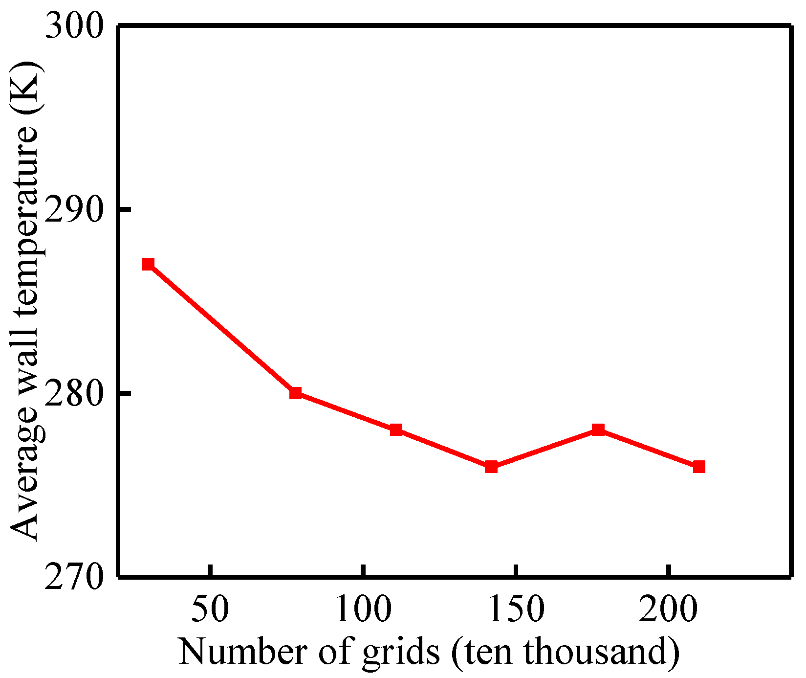
Divide into unstructured grids using ICEM CFD software 2020. There is a significant temperature difference between the cold flow medium and the mainstream gas. In order to further improve the accuracy of numerical simulation results, the mesh of the wall area of the cold flow channel and the gas film ring wall were densified. In order to obtain grid independence solutions, six different grid numbers were designed for the cooling model of the endoscope probe, and their effects on the average surface temperature of the probe were obtained, as shown in Figure 4. As shown in Table 2, the mainstream inlet boundary conditions for the independence verification remain unchanged, and the cold flow inlet boundary conditions are an absolute pressure of 0.5 Mpa and a temperature of 285 K within the range of the aircraft engine cooling system. The width of the annular cooling structure is 0.6 mm. The results show that when the number of grids is greater than 1.42 million, the average adiabatic cooling efficiency of the probe surface changes little with the number of grids. Therefore, the number of cooling model grids for subsequent endoscopic probes will be 1.42 million.
This article selects the SST k-ω model for steady-state calculations, which has good accuracy in both reverse pressure gradients and near wall regions, with y+values controlled below five. Set the inlet turbulence intensity to 5%. In order to verify the accuracy of the simulation results, the experimental results of Xie et al. [25] and the calculation results of F.R. [26] were compared and verified. It was found that the axial distribution of the spanwise average cooling efficiency of different turbulence models was consistent with the trend of the experimental results. The results obtained from the validation analysis in the literature indicate that the SST k-ω turbulence model is closest to the experimental results, and the SST k-ω model is more accurate in solving flow and heat transfer problems.

4. Results and Analysis

4.1. The Influence of Exit Width on the Cooling Characteristics of Hole Probe

By analyzing Figure 5, it can be concluded that the average and maximum temperatures of the probe mirror gradually decrease with the increase in the cooling ring width, while the cooling efficiency of the probe mirror gradually increases. Among them, the average temperature of the probe mirror decreased from 387.77 K to 300.25 K, and the highest temperature of the probe mirror decreased from 442.25 K to 342.05 K, indicating a significant cooling effect on the mirror surface.
By analyzing Figure 6, it can be concluded that the cold flow outlet flow rate of the annular probe gradually decreases with the increase in the cooling ring width, while the mirror cooling efficiency of the probe gradually increases. Among them, the cold flow outlet flow rate of the annular probe decreased from 2.69 mL/s to 0.62 mL/s, and the cooling effect of the mirror cooling was more significant. When the width of the cold flow outlet reaches 0.7 mm, the highest temperature and average temperature in Figure 5 are the lowest, indicating the best cooling effect. The cold flow outlet has the lowest flow rate, which can save more cold air volume. The larger the width of the cold flow outlet, the lower the mirror temperature of the hole probe.
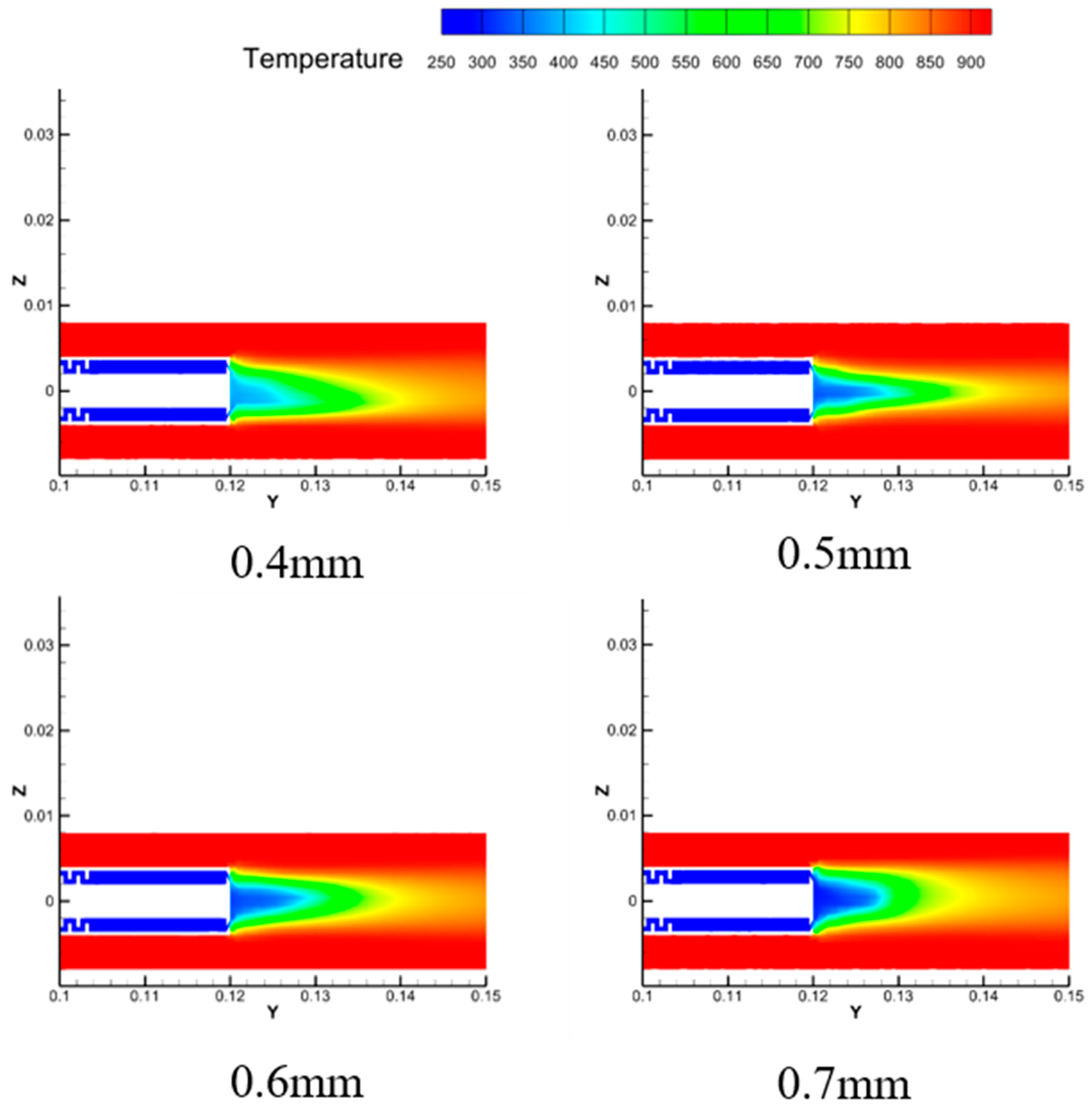
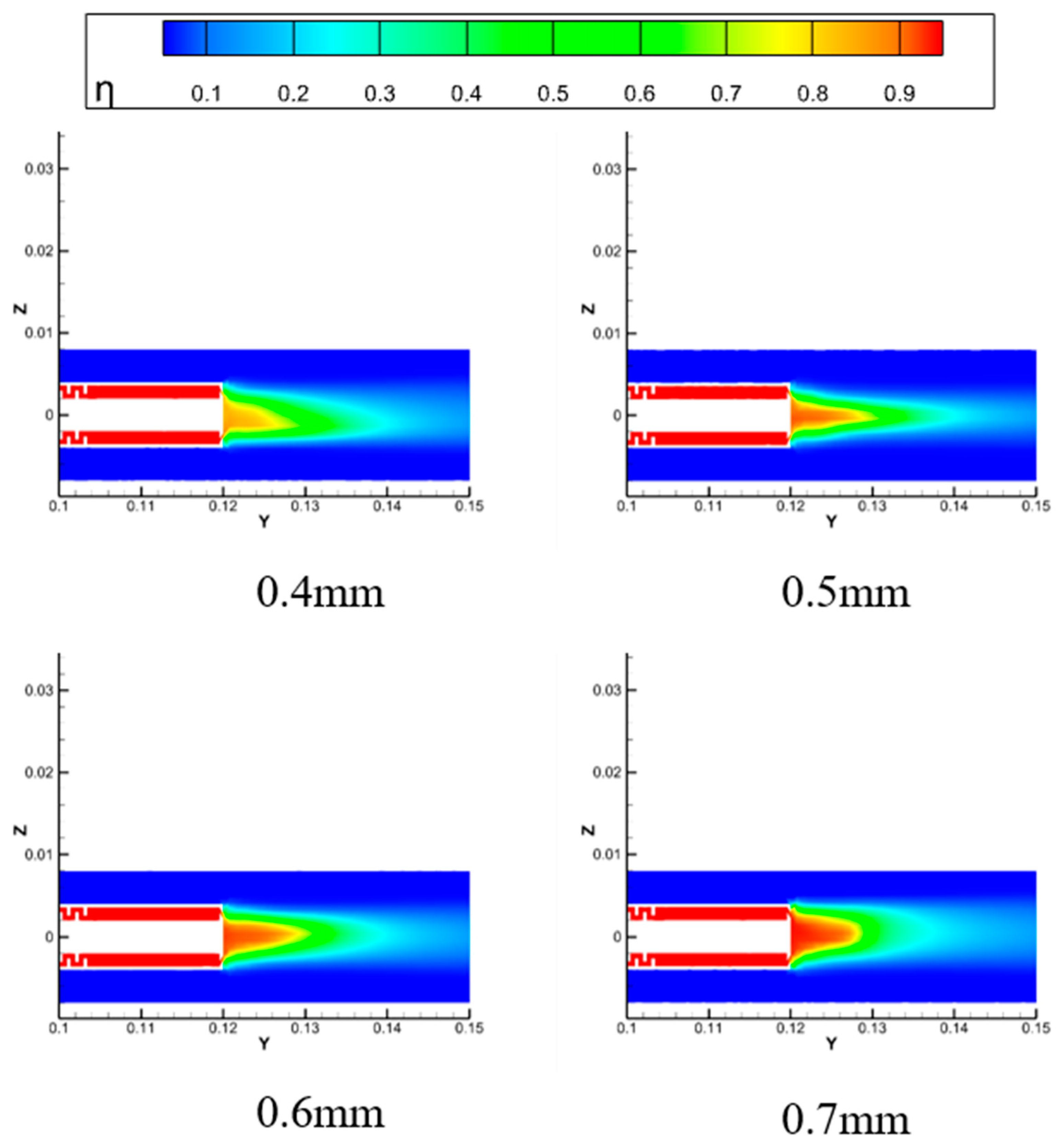
The distribution diagrams of longitudinal section temperature and cooling efficiency of hole probe under different outlet widths are shown in Figure 7 and Figure 8. It can be intuitively seen from the figure that as the width of the cooling ring increases, the cooling area of the hole probe lens mirror becomes larger. The reason is that when the width of the cooling ring is small, the airflow outflow is small. Although the cold flow velocity is fast, the gas flow rate is low. At this time, the lateral expansion of the cold flow is poor, and the mixing zone between the cooling airflow and the high-temperature environment is far away from the surface of the probe. Therefore, the hole probe cannot be fully cooled.
When the width of the cooling ring is 0.4 mm, the average surface temperature of the probe is much higher than 330 K, and the cold air cannot be unblocked laterally. When the width of the cooling ring increases to 0.6 mm, the average surface temperature of the probe is already below 330 K, and the lateral expansion of the cold air becomes good. When the width of the cooling ring increases to 0.6 mm and 0.7 mm, the cold airflow rate is larger and the cold airflow velocity is slower. There is more distribution of cooling air near the hole probe, and the lateral diffusion of cold air is better. The cold air blown out of the impact ring spreads more to the surrounding area, but due to the slower flow velocity, it is not fully cooled for the distant thermal environment field, resulting in a rapid temperature rise. This can also be seen intuitively from the cloud map of the cooling efficiency distribution of the hole probe in Figure 8.
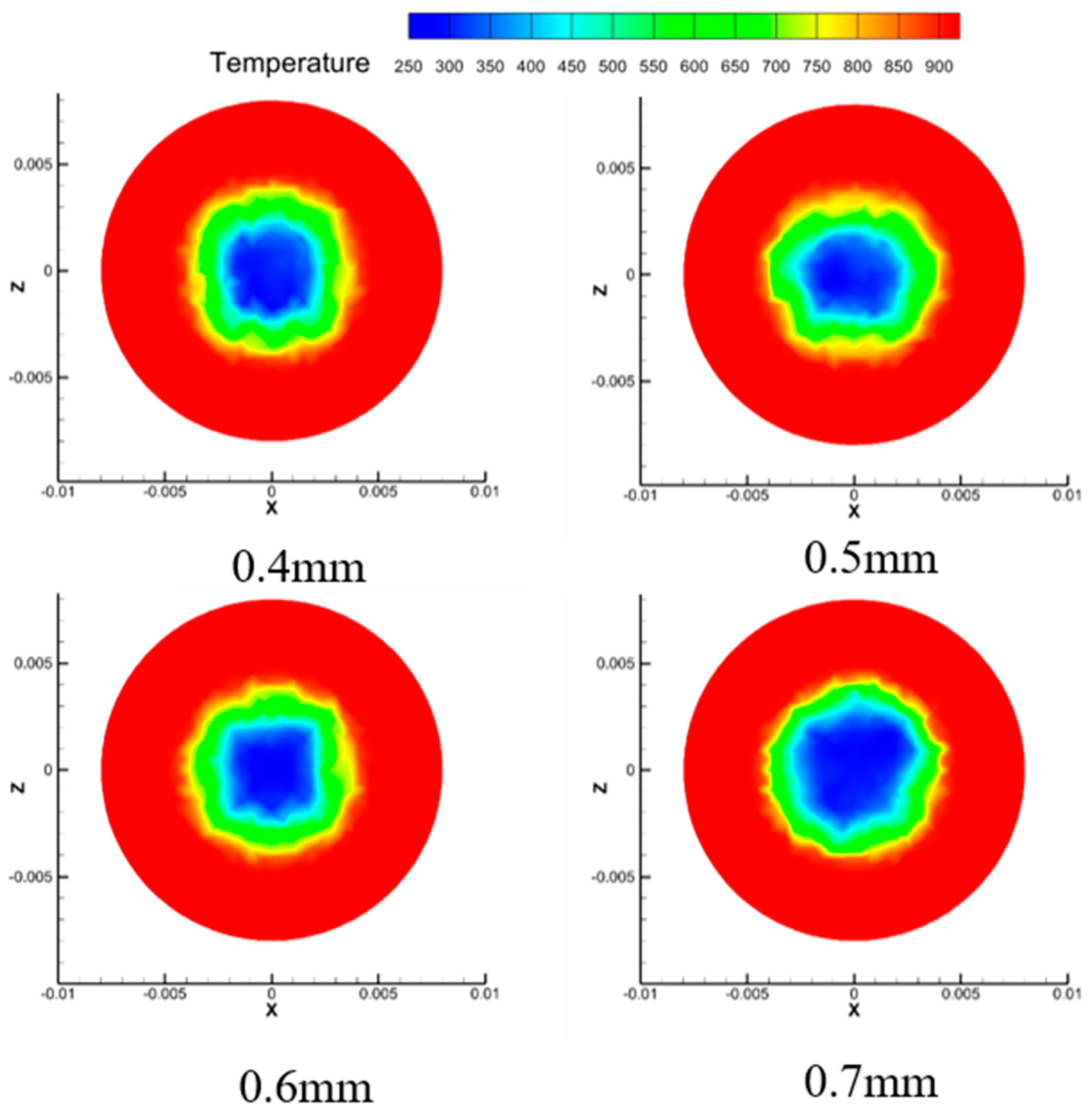
As the width of the cooling ring decreases, the mixing zone between the cooling airflow and the mainstream high temperature gradually moves away from the probe surface, as shown in Figure 9 and Figure 10. When the width of the cooling ring is small, the lateral diffusion of cold air is poor, the range of cold air blown out by the impact ring is small, and the impact heat transfer of the probe mirror is not comprehensive enough, so the cooling efficiency is not high. When the width of the cooling ring is 0.6 mm, the average surface temperature of the probe is below 330 K, and the lateral diffusion of cold air becomes good. When the width of the cooling ring is large, the lateral diffusion of cold air is good, and the cold air blown out of the impact ring spreads more around the ring, resulting in a larger heat exchange area with the probe mirror surface and more sufficient impact heat exchange, leading to a lower temperature of the probe mirror surface. When the width of the cooling ring increases by 0.1 mm, the average surface temperature of the probe decreases by 44 K, the highest surface temperature of the probe decreases by 57 K, and the flow rate through the impact ring decreases by 0.44 mL/s. When the width of the cooling ring increases by 0.2 mm, the average surface temperature of the probe decreases by 58 K, the highest surface temperature of the probe decreases by 60 K, and the flow rate through the impact ring decreases by 1.12 mL/s. When the width of the cooling ring increases by 0.3 mm, the average surface temperature of the probe decreases by 88 K, the highest surface temperature of the probe decreases by 100 K, and the flow rate through the impact ring decreases by 2.07 mL/s. As the width of the cooling ring increases, the frictional resistance at the outlet of the cold flow decreases, and the flow rate of the impact ring is reduced. Therefore, the lateral diffusion of cold air on the probe mirror surface is enhanced.

4.2. The Influence of Opening Angle on the Cooling Characteristics of Hole Probe

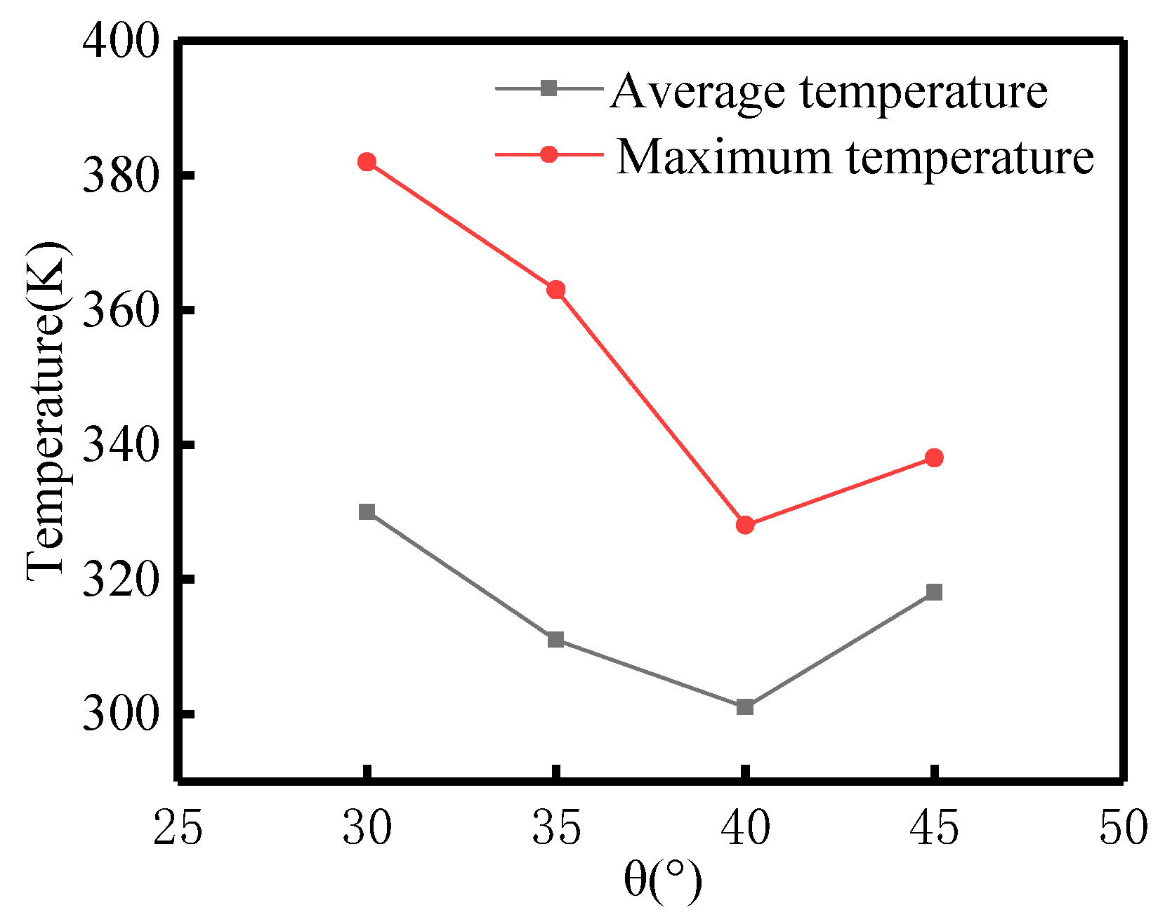
By analyzing Figure 11, it can be concluded that the average and maximum temperatures of the probe mirror surface decrease first and then increase with the opening angle of the cooling ring, and the cooling efficiency of the probe mirror surface increases first and then decreases. Among them, the average temperature of the probe mirror decreased from 330 K to 301 K, and the highest temperature of the probe mirror decreased from 382 K to 363 K, indicating a significant cooling effect on the mirror surface. As the opening angle of the cooling ring increases to a suitable angle, the cooling airflow impacts the probe mirror in an appropriate form, forming a stable film protective layer and improving the cooling performance.
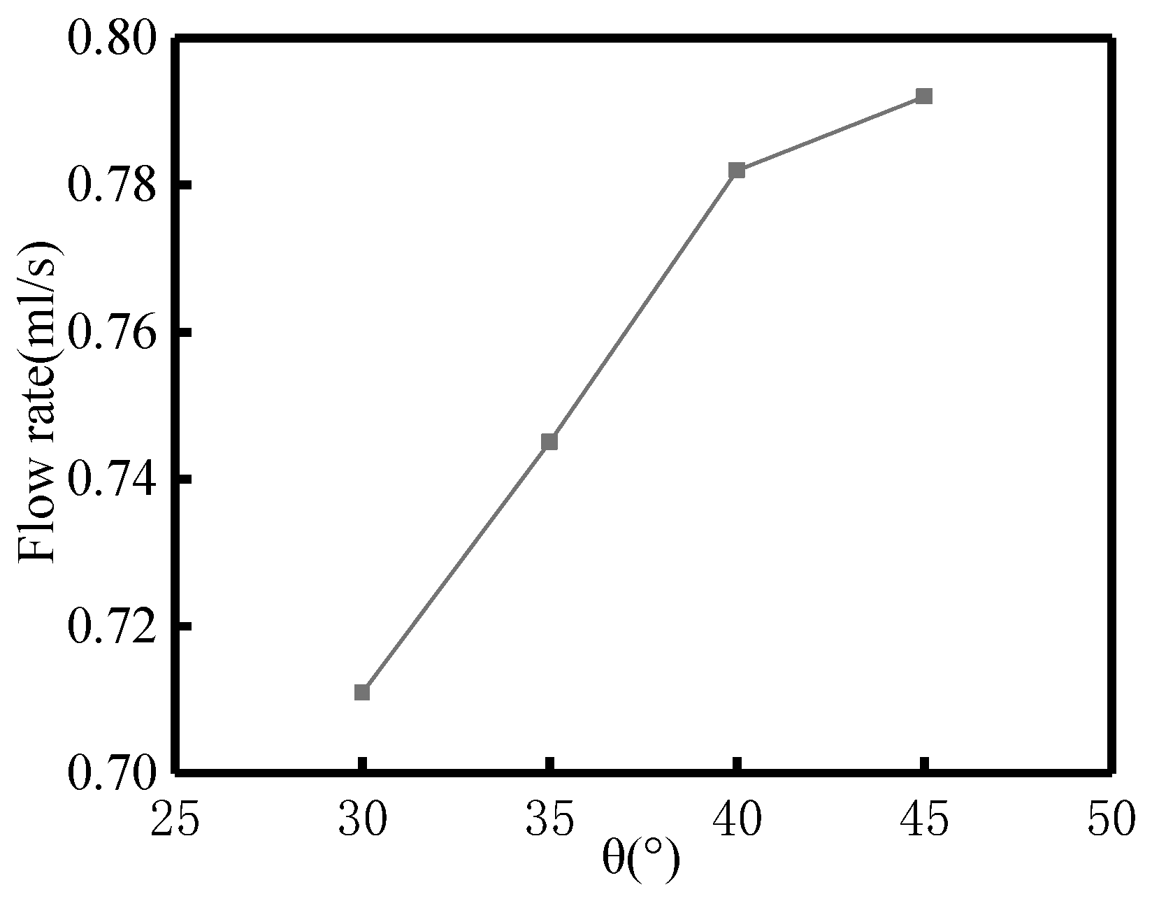
By analyzing Figure 12, it can be concluded that the cold flow outlet flow rate of the annular probe gradually increases with the increase in the cooling ring opening angle, and the mirror cooling efficiency of the probe gradually increases. Among them, the cold flow outlet flow rate of the annular probe increased from 0.711 mL/s to 0.792 mL/s, and the cooling effect of mirror cooling was more significant. When the angle of the cold flow slit reaches 40°, the maximum temperature, average temperature, and cooling efficiency of the curve reach their optimal results. Within a certain range, the larger the angle of the cold flow opening, the lower the mirror temperature of the hole probe, and the greater the amount of cold flow consumed.
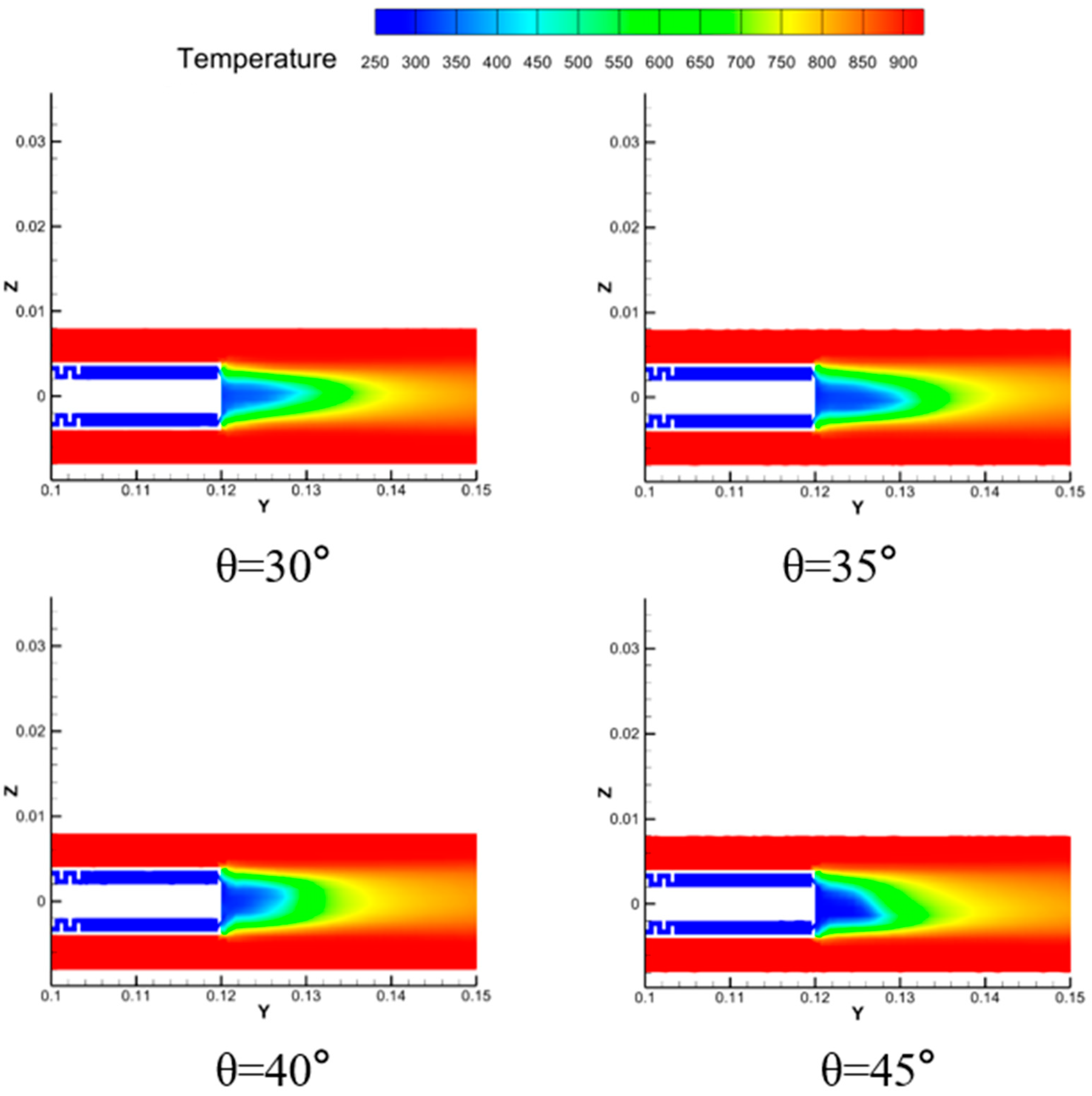
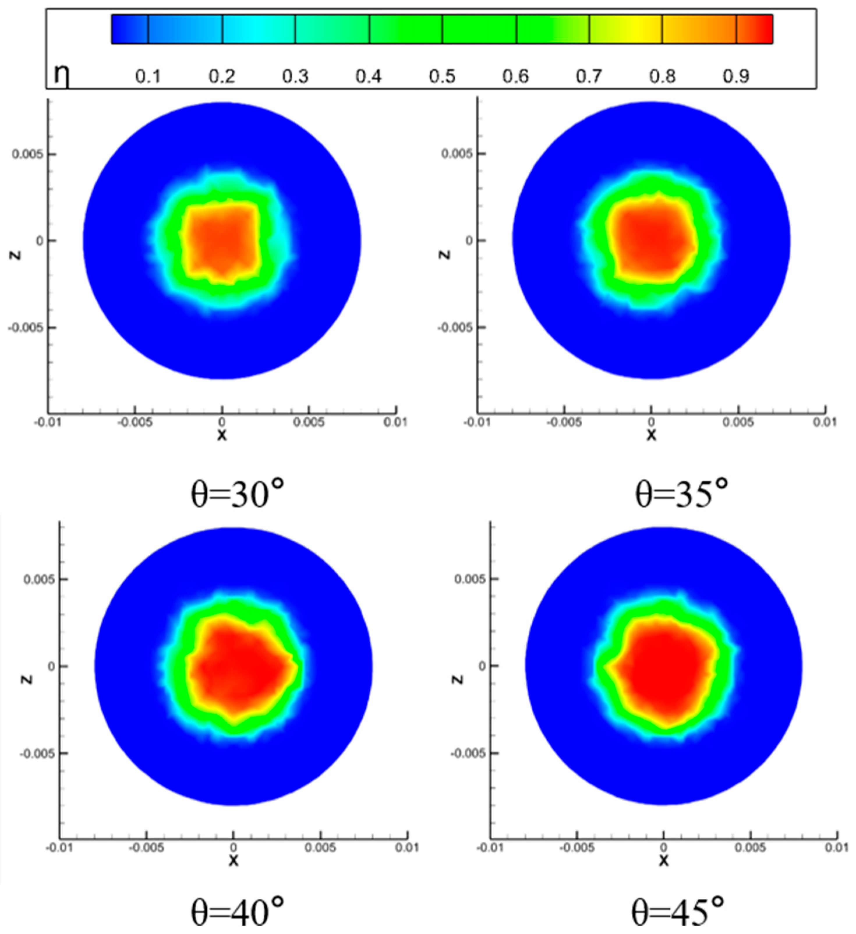
Figure 13 and Figure 14 show the temperature and cooling efficiency distribution of a circular cooling structure model with a slot width of 6 mm under the conditions of cold flow inlet pressure of 0.5 MPa, inlet temperature of 285 K, and cold flow of air. The influence of slot angles of 30 degrees, 35 degrees, 40 degrees, and 45 degrees on the cooling characteristics of the hole probe was analyzed. When the cold flow is sprayed at 30°, the cooling effect of the flow field behind the three-stage pressure drop structure is significant. However, when the droplets are sprayed at 35°, the cooling effect is better, with a larger cooling range than the 30° spray. Similarly, when sprayed at 40° or 45°, the cooling effect of the front section of the probe surface is significantly better than the previous two. When the inclination angle of the hole increases from 40° to 45°, the total amount of cold air at the cooling outlet of the hole probe decreases, and the average cooling efficiency decreases. This indicates that the airflow has a certain momentum direction, and after being impacted at a larger angle, the airflow can reach the probe mirror faster, forming a strong cooling area.
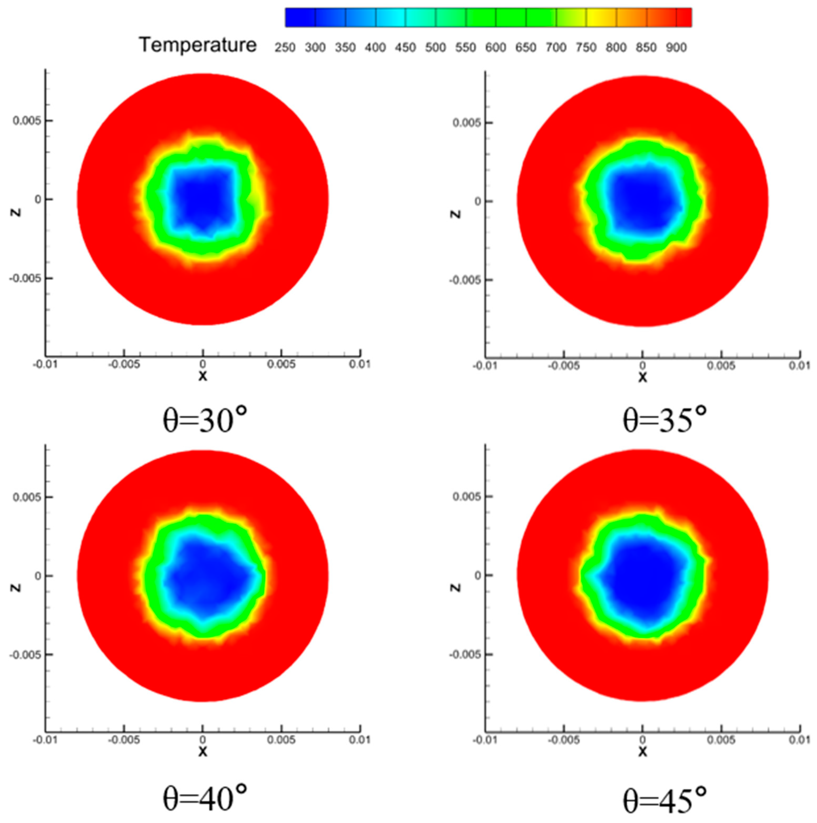
When the opening angle is small, the temperature in the high-temperature mixing zone is not low, resulting in a higher surface temperature of the probe, as shown in Figure 15 and Figure 16. When the mixing zone is close to the surface of the probe, the high-temperature mainstream is significantly affected, and the surface temperature of the probe is lower, resulting in a better cooling effect; when the mixing zone is far away from the surface of the probe, the surface temperature of the probe is higher and the cooling effect is poor. However, reasonable control of the opening angle can still ensure that the temperature does not exceed 330 K. When the opening angle increases from 30 degrees to 40 degrees, the average temperature of the probe mirror decreases from 330 K to 301 K. Without changing the opening width and position or reducing the opening angle within a certain range, there is a better cooling effect. The larger the opening angle, the farther away the direction of the cooling airflow is from the flat surface, making the mixing zone closer to the probe surface.

4.3. The Effect of Mixing Liquid Nitrogen on the Cooling Characteristics of Hole Probe

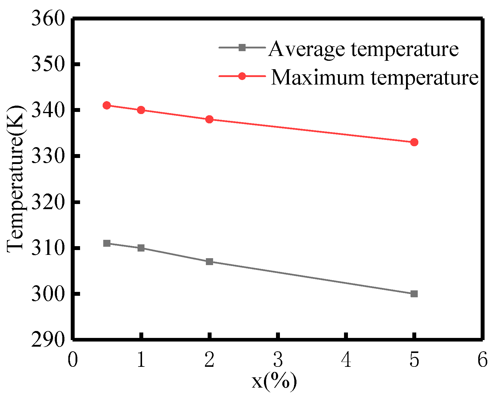
By analyzing Figure 17, it can be concluded that the average and maximum temperatures of the probe mirror surface are significantly reduced after mixing cold air with liquid nitrogen. The average temperature decreases from 311 K to 300 K, and the maximum temperature decreases from 341 K to 333 K, indicating a significant cooling effect. When the mixing ratio of liquid nitrogen reaches 5%, the maximum temperature, average temperature, and cooling efficiency of the curve reach their optimal results. The larger the proportion of liquid nitrogen mixed, the lower the mirror temperature of the hole probe.
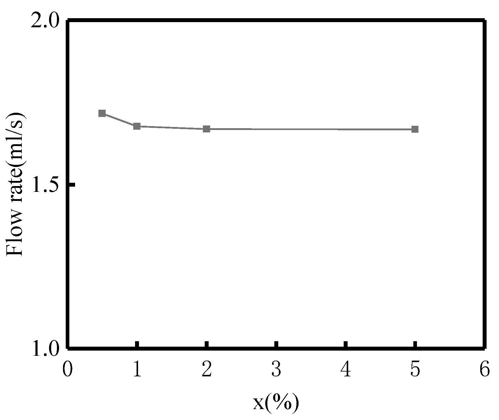
Figure 18 shows the distribution of flow rate at the cold flow outlet of the probe as a function of different proportions of mixed liquid nitrogen conditions. By analyzing the graph, it can be concluded that the cold flow outlet flow rate of the annular probe decreases significantly after mixing cold air with liquid nitrogen. The cold flow outlet flow rate of the probe decreases from 1.717 mL/s to 1.668 mL/s, with a certain degree of decrease in flow rate. When the mixing ratio of liquid nitrogen reaches 5%, the maximum temperature, average temperature, and cooling efficiency of the curve reach their optimal results. The larger the proportion of liquid nitrogen mixed, the lower the mirror temperature of the hole probe.
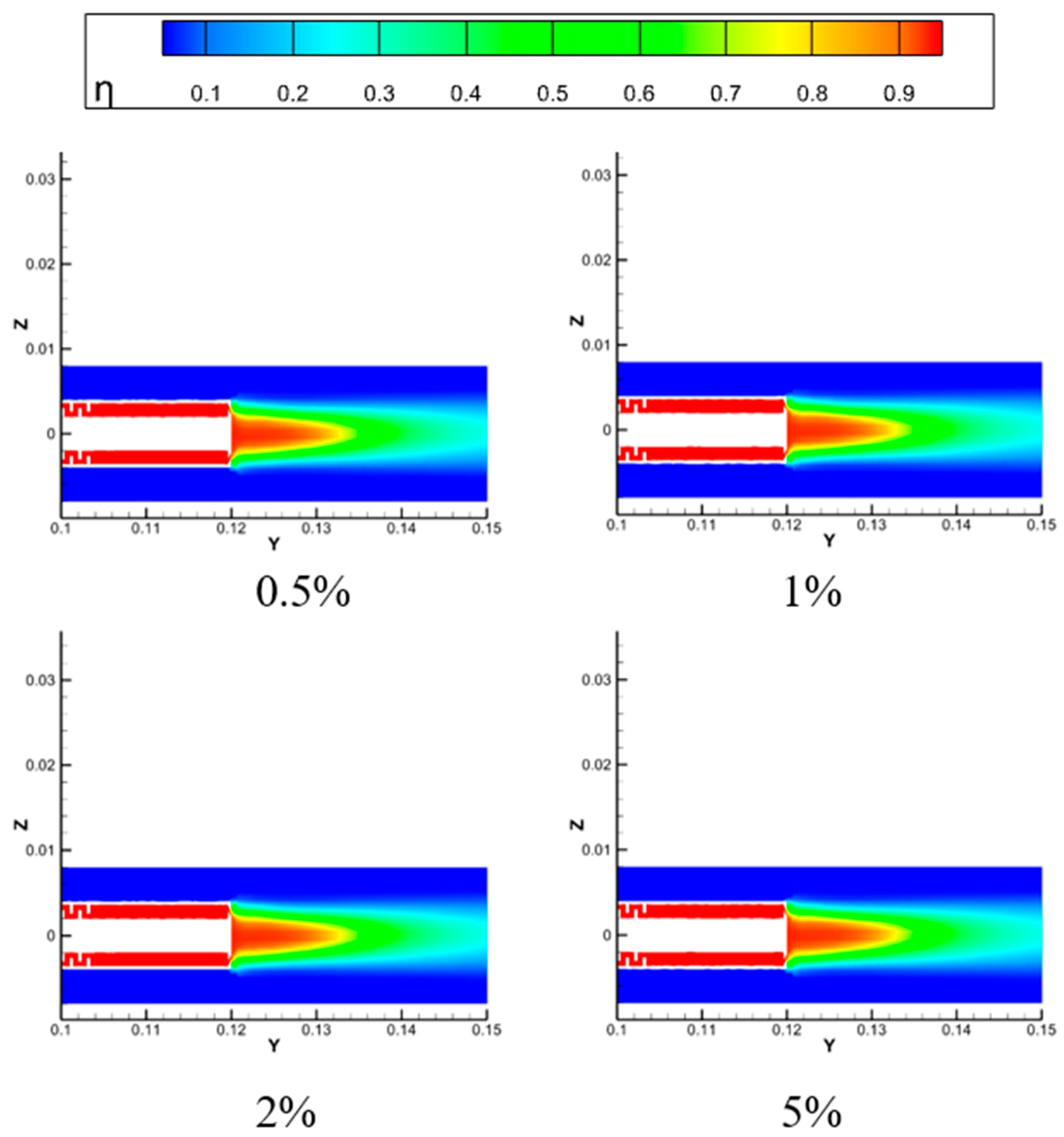
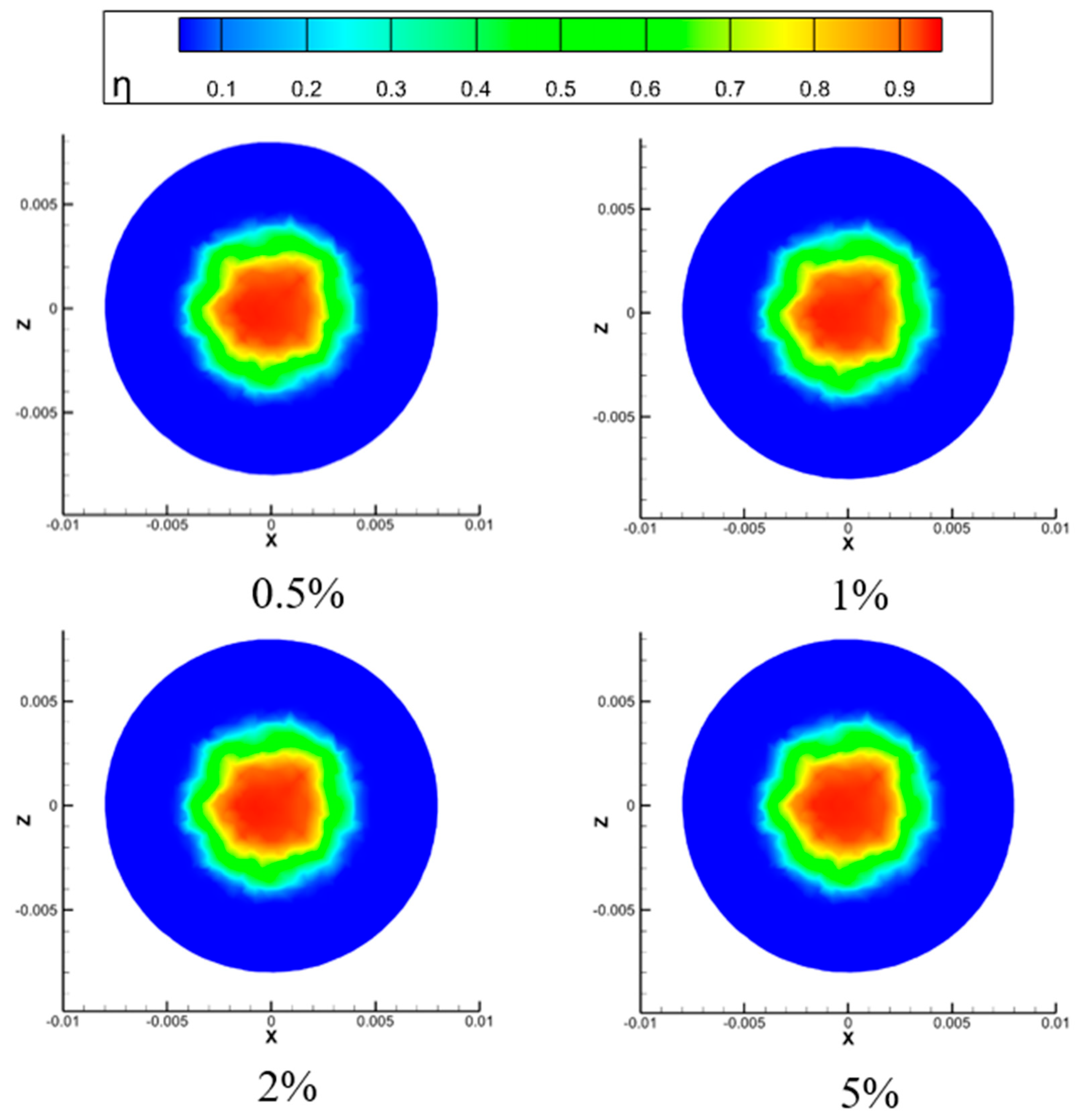
The distribution diagrams of longitudinal section temperature and cooling efficiency of the borehole probe under different mixed liquid nitrogen conditions are shown in Figure 19 and Figure 20. Under the conditions of a cold flow inlet pressure of 0.5 MPa, a cooling ring width of 0.6 mm, and an inlet temperature of 285 K, analyze the effect of mixing nitrogen gas in the cold flow on the cooling characteristics of the borehole probe. This article sets the nitrogen blending ratios of 0.5%, 1%, 2%, and 5% for comparative analysis. By analyzing Figure 19, it can be concluded that the average temperature and maximum temperature of the probe mirror surface are significantly reduced after mixing nitrogen into the cold airflow. The average temperature decreases from 311 K to 300 K, and the maximum temperature decreases from 341 K to 333 K, indicating a significant cooling effect. The analysis shows that the highest temperature, average temperature, cooling efficiency, and flow rate of the cold airflow are optimal when the nitrogen mixing ratio is 5%. Trace amounts of liquid nitrogen vaporization will absorb a certain amount of heat. When the mixing ratio is increased, the vaporization of liquid nitrogen rapidly reduces the temperature of the cold flow, effectively cooling the surface of the probe and improving cooling efficiency.
The larger the flow rate of liquid nitrogen in cold air, the wider the effective cooling range, and the better the cooling effect. However, it is necessary to comprehensively consider the flow rate and cost of liquid nitrogen storage tanks to obtain the optimal value of mixed liquid nitrogen flow rate. It can be seen that the local temperature after the impact ring decreases with the increase in flow rate proportion, and the decrease in local temperature after the impact ring is not significant. Therefore, it is not advisable to use a high flow rate ratio when the cooling effect is not significantly improved, as shown in Figure 21 and Figure 22. When the proportion of nitrogen mixed increases by 0.5%, the average surface temperature of the probe decreases by 1 K, the maximum surface temperature of the probe decreases by 1 K, and the flow rate through the impact ring decreases by 0.03 mL/s. When the proportion of nitrogen mixed increases by 1.5%, the average surface temperature of the probe decreases by 4 K, the maximum surface temperature of the probe decreases by 3 K, and the flow rate through the impact ring decreases by 0.041 mL/s. When the proportion of nitrogen mixed increases by 4.5%, the average surface temperature of the probe decreases by 11 K, the maximum surface temperature of the probe decreases by 8 K, and the flow rate through the impact ring decreases by 0.042 mL/s. When the mixing ratio of liquid nitrogen is larger, the vaporization of liquid nitrogen absorbs more heat, and the cooling effect of the entire cold flow is more significant, which improves the cooling efficiency of the hole probe.

5. Conclusions

This study conducted numerical simulations of the active cooling characteristics of an aircraft engine endoscope probe by establishing a three-dimensional fluid–solid conjugate heat transfer numerical model. This model can accurately reflect the flow, impact, and gas film coverage of the cooling gas in the cold flow channel and accurately reflect the temperature distribution of the probe mirror surface, providing reliability for quantitative evaluation of cooling methods.
(1)
The cooling gas in the annular structure can effectively reduce the temperature of the probe mirror, and the larger the outlet width, the better the cooling effect. The best annular cooling structure studied in this article is a circular ring structure with an outlet width of 0.7 mm. At a cold flow temperature of 285 K and a pressure of 0.5 MPa, the temperature of the endoscope probe can be reduced to 300.25 K, and the cooling effect of the hole probe mirror surface is the best. At the same time, the flow rate also rapidly decreases, reaching 0.62 mL/s at an outlet width of 0.7 mm, which not only effectively cools but also saves cold air volume. As the width of the cooling ring increases, the frictional resistance at the outlet of the cold flow decreases, and the flow rate of the impact ring is reduced. Therefore, the lateral diffusion of cold air on the probe mirror surface is enhanced. The width of the cooling ring outlet is a key parameter that affects the cooling efficiency of the probe.
(2)
The opening angle of the hole probe has a significant impact on the cooling effect of the hole probe. The larger the opening angle, the lower and then higher the average and maximum temperatures of the endoscope probe surface. As the opening angle of the cooling ring increases to a suitable angle of 40°, the cooling airflow impacts the probe mirror in an appropriate form, forming a stable film protective layer and improving the cooling performance. There is an optimal value for the opening angle of the cooling ring.
(3)
The larger the proportion of mixed liquid nitrogen, the lower the temperature of the probe mirror. A 5% proportion of mixed liquid nitrogen can reduce the temperature of the probe mirror by about 11 K. As the proportion of mixed liquid nitrogen in the cold air increases from 0.5% to 5%, the wall temperature of the hole probe gradually decreases and reaches a minimum value of 300 K at a mixing ratio of 5%. The cold flow rate also gradually decreases, reaching 1.67 mL/s at a mixing ratio of 5%. This indicates that the use of mixed liquid nitrogen for thermal protection measures in high-temperature environments in the future has broad prospects.
This study mainly conducted parametric and quantitative research on the active cooling scheme of endoscopic probes, proposed some optimization rules, and provided theoretical basis for the development of new hole probe probes in the future, providing guarantee for the operation and detection of aircraft engines. Further research can be conducted from the following aspects: studying the cooling characteristics of probes in more complex practical working environments; optimizing research using different cooling media; explore applications through sensors or motors.

Author Contributions

Conceptualization, H.Z. and R.X.; methodology, H.Z.; software, H.Z. and R.X.; validation, R.X.; formal analysis, J.P.; investigation, J.P.; resources, H.Z. and J.P.; data curation, L.J.; writing—original draft preparation, R.X.; writing—review and editing, R.X.; visualization, L.J.; supervision, C.F.; project administration, C.F.; funding acquisition, C.F. All authors have read and agreed to the published version of the manuscript.

Funding

This research received no external funding.

Data Availability Statement

The original contributions presented in the study are included in the article, further inquiries can be directed to the corresponding author.

Conflicts of Interest

The authors declare no conflict of interest.

References

  1. He, J.; Xue, W.; Zhang, W.; Huang, W.; Zhang, K.; Liu, C.; Wang, Y. Analysis and Development Prediction of Technical Characteristics of Aircraft Engine Turbine Components. Gas Turbine Test. Res. 2025, 38, 20–32. [Google Scholar] [CrossRef]
  2. Xie, W.; Luo, J. Research progress of laser additive manufacturing technology in turbine blade materials. China Mater. Prog. 2025, 44, 750–760. [Google Scholar]
  3. Yan, G.; Yan, H.; Jiang, N.; Liu, Y.; Liang, Y.; Zhao, J. Experimental Study on Flow and Heat Transfer Performance of Air Coolers for New Aircraft Engines. Aircr. Engines 2023, 49, 48–53. [Google Scholar]
  4. Wen, Q.; Pei, X.; Tian, H.; Hou, L. Study on the Influence of Air Oil Heat Exchanger on the Overall Performance of Variable Cycle Aircraft Engine. Propuls. Technol. 2023, 44, 39–48. [Google Scholar]
  5. Li, Y. Analysis of Damage and Repair Technology of Aircraft Engine Blades. Intern. Combust. Engine Parts 2025, 108–110. [Google Scholar] [CrossRef]
  6. Lai, J. Overview of Cooling Technology for Aircraft Engine Turbine Blades. New Ind. 2021, 11, 39–40. [Google Scholar]
  7. Xiao, Y.; Cheng, R.; Sun, Y.; Zhou, C.; Xue, X.; Shang, S. Numerical simulation of phase change medium injection cooling for high-temperature components of aircraft engines. Aero Engine 2025, 51, 90–96. [Google Scholar]
  8. Fei, W.; Dan, Y.; Wang, M.; Tan, X.; Zhang, J. Numerical Study on Ultrasonic Film Cooling of Supersonic Turbine Blades. Propuls. Technol. 2016, 37, 916–921. [Google Scholar]
  9. Chen, S.; Dan, Y.; Zhang, J.; Tan, X.; Fei, W. Flow characteristics and film cooling properties of supersonic flow field in turbine blade cascade. J. Aeronaut. Dyn. 2013, 28, 2448–2454. [Google Scholar]
  10. Li, Z.; Zhang, Y.; Dong, W.; Chen, J.; Deng, B. Optimization design of efficient arrangement of gas film cooling holes on the end wall of turbine blades. J. Shanghai Jiao Tong Univ. 2025, 1–17. [Google Scholar] [CrossRef]
  11. Li, X.; Zhang, S.; Ye, Z.; Chen, J. Research on Thermal Protection Performance of Infrared Temperature Probe for Turbine Blades. Therm. Power Eng. 2024, 39, 97–105. [Google Scholar]
  12. Ye, Z.; Li, X.; Liu, Y.; Tan, Z.; Huai, X. Numerical simulation study on the protective performance of infrared temperature probe. J. Eng. Thermophys. 2024, 45, 205–211. [Google Scholar]
  13. Zhang, J.; Sun, B.; Zheng, L. Experimental study on supersonic film cooling with discrete holes in a circular straight pipe. J. Aeronaut. Dyn. 2013, 28, 813–818. [Google Scholar]
  14. Xue, H.; Chen, X.; Zhang, X. Research on wall temperature calculation of axisymmetric vectoring nozzle under various forms of film cooling. Adv. Aerosp. Eng. 2014, 5, 404–410. [Google Scholar]
  15. Zhang, X.; Wang, X. Comparative study on cooling effects of various film cooling models. J. Aeronaut. Dyn. 2002, 17, 475–479. [Google Scholar]
  16. Zhang, T. Research on the Design of Film Cooling Structure for Tail Nozzle. Master’s Thesis, Dalian University of Technology, Dalian, China, 2021. [Google Scholar]
  17. Zhai, G.; Yang, H.; Gong, W.; Wu, F.; Zeng, J.; Fu, X.; Gao, T. Numerical Analysis on Thermal and Flow Performance of Honeycomb-Structured Microchannel Cooling Plate for IGBT. Energies 2025, 18, 4455. [Google Scholar] [CrossRef]
  18. Vekariya, P.B.; Subbaiah, R.; Mashru, H.H. Hydraulics of microtube emitters: A dimensional analysis approach. Irrig. Sci. 2011, 29, 341–350. [Google Scholar] [CrossRef]
  19. Wang, H.; Xie, S.; Sai, Q.; Zhou, C.; Lin, H.; Chen, E. Experiment study on pressure drop of a multistage letdown orifice tube. Nucl. Eng. Des. 2013, 265, 633–638. [Google Scholar] [CrossRef]
  20. Zhang, S.; Zheng, H.; Zhang, Z.; Zhang, T.; Yang, X. Performance evaluation of film holes used for cooling the optical window of a sensor probe. Numer. Heat Transf. Part A Appl. 2025, 86, 6029–6054. [Google Scholar] [CrossRef]
  21. Xie, B.; Peng, F.; Lin, H.; Zhang, J.; Han, X.; Zhou, L.; Zhou, B. Research and application of a digital industrial endoscope protection fixture Chongqing Changan Automobile Co., Ltd. Jiangbei Engine Fact. 2020, 379–381. [Google Scholar] [CrossRef]
  22. Tang, Z.; Wang, W. Error behavior analysis during engine hole probing. Equip. Manag. Maint. 2022, 39–40. [Google Scholar] [CrossRef]
  23. Wei, X. Risk Management in the Inspection Process of Aircraft Engine Holes. Aviat. Maint. Eng. 2018, 43–45. [Google Scholar] [CrossRef]
  24. Sun, H. Application of Industrial Endoscope in CFM56 Civil Aviation Engine Maintenance. Sci. Technol. Inf. 2019, 17, 77–78. [Google Scholar]
  25. Xie, G.; Liu, C.; Niu, J.; Ye, L.; Wang, R. Experimental investigation on analogy principle of conjugate heat transfer for effusion/impingement cooling. Int. J. Heat Mass Transf. 2020, 147, 118919. [Google Scholar] [CrossRef]
  26. Menter, F.R. Two-equation eddy-viscosity turbulence models for engineering applications. AIAA J. 2012, 32, 1598–1605. [Google Scholar] [CrossRef]
Figure 1. Side view of cooling model for endoscope probe.
Aerospace 12 00962 g001
Figure 2. Top view of cooling model for endoscope probe.
Aerospace 12 00962 g002
Figure 3. Calculation domain of cooling model for endoscope probe.
Aerospace 12 00962 g003
Figure 4. Grid independence verification.
Aerospace 12 00962 g004
Figure 5. Temperature distribution of probe mirror surface under different cold flow outlet widths.
Aerospace 12 00962 g005
Figure 6. Flow distribution of cold flow outlet under different widths of cold flow outlet.
Aerospace 12 00962 g006
Figure 7. Temperature distribution of longitudinal section of borehole probe.
Aerospace 12 00962 g007
Figure 8. Distribution of cooling efficiency of longitudinal section of borehole probe.
Aerospace 12 00962 g008
Figure 9. Temperature distribution of the mirror surface of the hole probe.
Aerospace 12 00962 g009
Figure 10. Distribution of mirror cooling efficiency of hole probe.
Aerospace 12 00962 g010
Figure 11. Temperature distribution of probe mirror surface at different seam angles.
Aerospace 12 00962 g011
Figure 12. Flow distribution of cold flow outlet at different opening angles.
Aerospace 12 00962 g012
Figure 13. Temperature distribution of longitudinal section of hole probe at different opening angles.
Aerospace 12 00962 g013
Figure 14. Distribution of cooling efficiency of longitudinal section of hole probe at different opening angles.
Aerospace 12 00962 g014
Figure 15. Temperature distribution of the mirror surface of the hole probe at different opening angles.
Aerospace 12 00962 g015
Figure 16. Distribution of mirror cooling efficiency of hole probe at different opening angles.
Aerospace 12 00962 g016
Figure 17. Temperature distribution of probe mirror surface under different proportions of liquid nitrogen mixing conditions.
Aerospace 12 00962 g017
Figure 18. Flow distribution of cold flow outlet under different proportions of mixed liquid nitrogen conditions.
Aerospace 12 00962 g018
Figure 19. Temperature distribution of longitudinal section of borehole probe.
Aerospace 12 00962 g019
Figure 20. Distribution of cooling efficiency of longitudinal section of borehole probe.
Aerospace 12 00962 g020
Figure 21. Temperature distribution of the mirror surface of the hole probe.
Aerospace 12 00962 g021
Figure 22. Distribution of mirror cooling efficiency of hole probe.
Aerospace 12 00962 g022
Table 1. Boundary conditions.
ParameterNumerical Value
Mainstream inlet temperature/K900
Mainstream inlet pressure/Pa101,325
Mainstream export temperature/K900
Mainstream export pressure/Pa101,325
Cold flow temperature/K285
Exit width/mm0.4, 0.5, 0.6, 0.7
Opening angle/°30, 35, 40, 45
Mixing ratio of liquid nitrogen/%0.5, 1, 2, 5
Table 2. Conditions for lattice independence verification.
Temperature/KPressure/Pa
Hot flow inlet900101,325
Cold flow inlet250500,000
Disclaimer/Publisher’s Note: The statements, opinions and data contained in all publications are solely those of the individual author(s) and contributor(s) and not of MDPI and/or the editor(s). MDPI and/or the editor(s) disclaim responsibility for any injury to people or property resulting from any ideas, methods, instructions or products referred to in the content.