Article

Angular Motion Stability of Large Fineness Ratio Wrap-Around-Fin Rotating Rockets

1
School of Aerospace Engineering, Beijing Institute of Technology, Beijing 100081, China
2
Xi’an Modern Control Technology Research Institute, Xi’an 710065, China
*
Author to whom correspondence should be addressed.
Aerospace 2025, 12(10), 890; https://doi.org/10.3390/aerospace12100890
Submission received: 17 July 2025 / Revised: 21 September 2025 / Accepted: 29 September 2025 / Published: 30 September 2025

Abstract

Long-range rotating wrap-around-fin rockets may exhibit non-convergent conical motion at high Mach numbers, causing increased drag, reduced range, and potential flight instability. This study employs the implicit dual time-stepping method to solve the unsteady Reynolds-averaged Navier–Stokes (URANS) equations for simulating the flow field around a high aspect ratio wrap-around-fin rotating rocket at supersonic speeds. Validation of the numerical method in predicting aerodynamic characteristics at small angles of attack is achieved by comparing numerically obtained side force and yawing moment coefficients with experimental data. Analyzing the rocket’s angular motion process, along with angular motion equations, reveals the necessary conditions for the yawing moment to ensure stability during angular motion. Shape optimization is performed based on aerodynamic coefficient features and flow field structures at various angles of attack and Mach numbers, using the yawing moment stability condition as a guideline. Adjustments to parameters such as tail fin curvature radius, tail fin aspect ratio, and body aspect ratio diminish the impact of asymmetric flow induced by the wrap-around fin on the lateral moment, effectively resolving issues associated with near misses and off-target impacts resulting from dynamic instability at high Mach numbers.

1. Introduction

Long-range rockets typically have two stabilization methods. One is to provide gyroscopic stability through spin, and the other is to generate stabilizing moments using tail fins. For tube-launched rockets to be implemented, the tail fins must be folded, and among all folding schemes, the wrap-around fins (WAFs) that allow circumferential folding are the most optimal solution. To meet the speed and range demands of rockets, mitigate mass imbalance, thrust misalignment, and aerodynamic asymmetry, as well as streamline the control system, wrap-around-fin rockets commonly utilize rotational flight.
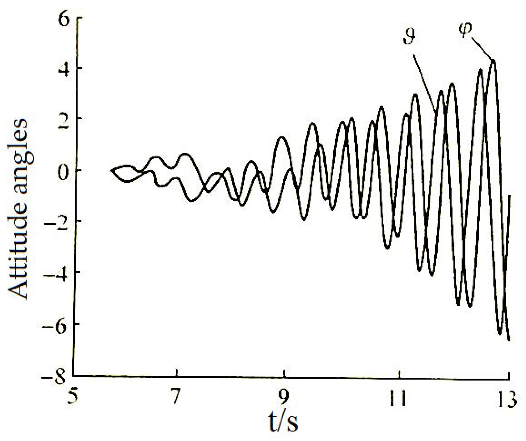
Wrap-around-fin rotating rockets generate force and moment perpendicular to the attack angle plane, referred to as out-of-plane force/moment in this context. Its generation is mainly caused by two factors. Firstly, the Magnus effect induced by the coupling of the angle of attack and rotational motion causes asymmetric distortions in the flow on both sides of the attack angle plane, resulting in out-of-plane forces and moments known as Magnus force/moment [1]; secondly, the asymmetry in the shape of the wrap-around fin induces special characteristics of side force and yawing moment [2]. Although the out-of-plane force is usually only 1~10% of the normal force, the out-of-plane moment has a significant impact on the dynamic stability of the rocket. The divergent conical motion induced by it can lead to flight failure. For example, the 140 mm wrap-around-fin rocket from Spain started to exhibit diverging conical motion 1.5 s after engine operation ceased, causing a 60% reduction in flight speed over the next 1.5 s, resulting in 9 catastrophic flights out of 28 experiments [3]. Diverging conical motion has also been observed during the development of controlled and uncontrolled rockets in China [4,5], as illustrated in Figure 1; therefore, the study of conical motion stability in rotating rockets is an important research field. Accurately predicting the aerodynamic characteristics of rotating rockets and gaining a deep understanding of the mechanisms generating out-of-plane force/moment will be an important foundation for stability analysis.
Researchers have conducted extensive studies on the longitudinal aerodynamic characteristics, self-induced rolling moment, and rolling moment reversal issues associated with wrap-around-fin rockets. Research shows that flat-plat-fin (FPF) and wrap-around-fin rockets with the same projected area and shape exhibit the same static stability coefficient, pressure center coefficient, and pitch damping at small angles of attack [6]. Stevens conducted experiments to compare the aerodynamic characteristics of flat-fin and wrap-around-fin rockets, revealing the issue of multiple reversals of the rolling moment for the wrap-around-fin rocket at supersonic speeds [2]. Subsequently, many researchers studied the effects of geometric parameters, such as the curvature radius, leading edge, and trailing edge shapes of wrap-around fins, on the rolling moment through experiments and steady-state numerical calculations. The results indicate that the strong shock waves on the concave surface of wrap-around fins, vortex systems at the connection of the convex surface and body, and the mutual interference of adjacent fin shock waves are the main reasons for the generation and reversal of the self-induced rolling moment [7,8,9,10,11,12]. Different wave and vortex systems near the flat fins and wrap-around fins directly affect the distribution of surface pressure, leading to significant differences in out-of-plane force/moment characteristics between the two. Additionally, the reversal of the rolling moment may change the rotation direction of the rocket, influencing the rotation-induced Magnus forces and moments, which could play a critical role in the dynamic stability of the rocket under critical conditions.
When in rotation, the out-of-plane force and moment of a wrap-around-fin rocket consist of a static component (static side force and yawing moment) and a Magnus component (Magnus force and moment). The former is only associated with the roll angle and is independent of the rotation rate, while the latter is induced solely by the rotation rate. Examining pressure distribution during the reversal of the rolling moment shows that the wrap-around-fin configuration displays a significant non-axisymmetric trait, where the static out-of-plane force and moment are relatively more pronounced than the Magnus force and moment at low rotation rate. G. Abate studied the impact of base cavities on the aerodynamic characteristics of rotating wrap-around-fin rockets through flight experiments, finding that there is a solution for eliminating dynamic instability regions by optimizing the rotation rate, geometric configurations of the fin and body, and geometric configurations of the cavity [13]. J. Morote and G. Liano conducted numerical calculations on the steady aerodynamic characteristics of a 140 mm wrap-around-fin rocket using the inviscid Euler equations, investigating the effects of changes in fin span and chord length on the aerodynamic characteristics. They successfully reduced the out-of-plane moment characteristics of the rocket through modifications [3]. Guoqing Zhang obtained the aerodynamic characteristics of wrap-around-fin rockets by solving the steady N-S equations, focusing on the effects of factors such as fin aspect ratio, curvature radius, installation angle, and number of fins on the out-of-plane force and moment characteristics. The results indicate that reducing the fin aspect ratio or increasing the curvature radius leads to reduced out-of-plane force characteristics [14]. These two studies have limited investigation into the mechanism of induced out-of-plane force and moment caused by non-axisymmetric shapes and have overlooked the impact of rotational motion. In earlier work, Omer and Gokmen utilized ballistic experimental data to investigate the impact of the Magnus effect on the flight stability of wrap-around-fin missiles under transonic and low supersonic conditions. The results indicate that considering only the static out-of-plane moment characteristics of the wrap-around fin may lead to erroneous outcomes, highlighting the necessity to simultaneously consider the static out-of-plane force/moment, Magnus force/moment for an accurate analysis of missile flight stability [15].
Therefore, this study conducted numerical simulations of the flow field around wrap-around-fin rockets under supersonic conditions with steady and unsteady rotation by solving the unsteady Reynolds-averaged Navier–Stokes equations, revealing the flow mechanisms inducing out-of-plane force/moment. This includes the structures of shock waves/expansion waves induced by the fins and their interference effects on the missile body. The study also compared and analyzed the contributions of the Magnus force/moment induced by rotational motion and the side force/yawing moment generated by non-axisymmetric shapes to the overall out-of-plane force/moment characteristics of the rocket. The variations in aerodynamic characteristics with angle of attack and Mach number were also calculated. The rocket’s angular motion process was analyzed by combining the angular motion equations. The conditions that the aerodynamic moment coefficients must meet for dynamic stability were derived. Subsequently, through shape optimization, such as altering the curvature radius of the fins, fin aspect ratio, and body aspect ratio, the out-of-plane force/moment of the wrap-around-fin rocket was reduced, effectively resolving issues associated with near misses and off-target impacts resulting from dynamic instability at high Mach numbers. In conclusion, this study explains the potential and reasons for the divergence of angular motion in wrap-around-fin rockets from an aerodynamic perspective, offering strong references and guidance for the design of related rotating rockets.

2. Numerical Approach

2.1. Numerical Methods

The fluid motion control equations in this study adopt the integral form of the Navier–Stokes equations based on the implicit dual time-stepping method:
t V W d V   +   Γ ε V Q d V   +   F G d A   =   V H d V
W = ρ ρ u ρ v ρ w ρ E ,   Q = p u v w T ,   F = ρ v ρ v u + p i ρ v v + p j ρ v w + p k ρ v E + p v ,   G = 0 τ x i τ y i τ z i τ i j v j + f ,   Γ = θ 0 ρ T θ v ρ I ρ T v θ H δ ρ v ρ T H + ρ C P
where W is a convective term, Γ and Q denote the preconditioning matrix and the primitive variables, F and G are the inviscid and viscous flux vectors, H is the source term, and V represents the cell volume. In Equation (2), ρ represents the density, p denotes the pressure, τ is the shear stress, and v = [u, v, w] is the fluid velocity in the moving reference frame. In the preconditioning matrix, I represents the identity matrix, δ equals 1 in an ideal gas, Cp is the specific heat capacity, H is enthalpy, and the expressions for parameters θ and ρT are as follows:
ρ T = ρ T p = c o n s t = p / R T 2 ,   θ = 1 / U r 2 ρ T / ρ C p
where Ur is the local reference velocity; for an ideal gas, its expression is
U r = λ c , v , c ,   v < λ c λ c < v < c v > c
where c is the speed of sound and λ is a small quantity on the order of 10−5 to prevent singularities.
The finite volume method is used to solve the governing equations, the second-order upwind scheme is applied for spatial discretization, the Roe Flux Difference Splitting scheme is used for convective flux, and the gradient is solved using the least squares method. The rotation of the missile induces strong shear flow, thus the SST k-ω model [16] was employed in numerical simulations of the rotational flow around the rockets. It accurately captures phenomena such as shear flow from rotation, asymmetric adverse pressure gradient flow, and asymmetric flow separation. The dual time-step method comprises a physical time step that describes the motion of the object, as well as an inner virtual time step for converging the Reynolds-averaged N-S equations. In this context, t denotes the physical time step, while ε signifies the virtual time step in the time integration algorithm. During numerical computations, the rotation rate is initially set to 0 for steady-state calculations, and then transient calculations are performed using the results from the steady-state calculations as the initial condition, enabling rapid and stable convergence of results.

2.2. Pitch Damping Stability Derivatives

The Pitch Damping Stability Derivatives of a rocket were calculated using the transient planar pitching method (also referred to as the forced planar pitching or forced oscillation method) [17]. In this approach, the rocket’s motion about its center of mass in the angle of attack plane is described as follows:
α ( t ) = α 0 + Asin ( ω t )
where A is the pitch motion amplitude, α 0 is the mean angle of attack, and ω is the pitch angular velocity. For forced planar pitching, the pitch rate and angle-of-attack rate are equal; that is,
ω = α ˙
For simplification, a reduced pitch frequency k and the pitch frequency f are defined as
k = ω D V ,   f = 1 T = k V 2 π D
where V is the free-stream velocity, D is the rocket diameter, and T denotes the period of oscillation.
According to the test results in reference [17], for unsteady pitch motion calculations, the number of physical time steps for each oscillation cycle is set as N = 200, and the duration of each physical time step is
Δ t = T N = 2 π D N k V
The first-order Taylor series expansion of in-plane forces and moments for transient planar pitching motion is
C j ( t ) = C j 0 + C j α α ( t ) + C j q ω ( t ) D V + C j α ˙ α ˙ ( t ) D V , j = N , m ( N o r m a l   f o r c e , P i t c h i n g   m o m e n t )
where Cj0 is the zero-angle-of-attack static coefficient and C is the angle-of-attack derivative coefficient. Integrating the above equation yields
C j q + C j α ˙ = 2 V L [ C j ( t ) C j 0 C j α ( t ) ] d α α ˙ ( t ) d α
Substituting Equations (5) and (7) into Equation (10) results in
C j q + C j α ˙ = 2 V π A D 0 T C j ( t ) cos ( 2 V k D t ) d t

2.3. Equations of Angular Motion and Stability Criteria

The homogeneous equations for linearized angular motion of the missiles take the following form [18,19], which allows for the investigation of how complex angles of attack respond to initial disturbances:
Δ ¨ + H i P Δ ˙ M + i P T Δ = 0 ,   Δ = α + i β
The specific expressions for the parameters H, M, T, and P are
H = ρ S / 2 m C L α C D k y - 2 C m q + C m α ˙ M = ρ S / 2 m L k y - 2 C m z α T = ρ S / 2 m C L α k x - 2 C m y α , ω ¯ P = I x / I y ω x / V
where k x , y = I x , y / m L 2 . The roots of the characteristic equation can be expressed as
l 1 , 2 = 1 2 H i P ± H i P 2 + 4 M + i P T 2
Setting l1 = λ1 + 1, l2 = λ2 + 2, then λi (i = 1, 2) is the damping factor; ensuring its value is less than zero guarantees the dynamic stability of the rotating rocket. Through derivation, the sufficient and necessary condition for the stability of the angular motion of the rotating projectile can be obtained as follows:
H > 0 1 1 / S g > 0 1 / S g < 1 S d 2
where the gyroscopic stability factor Sg = P2/4M, and the dynamic stability factor Sd = 2T/H − 1. The criteria for the derivative of the lateral moment coefficient can be determined based on the stability conditions mentioned above.
If Sd < 0, then
1 1 / S g < S d < 0
Substituting the expression of the stability factor into the equation results in
1 4 M P 2 < 2 T H 1
Setting τ = 1 4 M / P 2 and substituting the specific expression of each term into the above equation results in
I x 2 I y C m q + C m α ˙ + I x 2 m L 2 C L α + C D < C m y α , ω ¯ < 1 τ I x 2 I y C m q + C m α ˙ + I x C D 2 m L 2 + τ + 1 I x 2 m L 2 C L α
If Sd > 0, then
0 < S d < 1 1 / S g
Substituting the expression of the stability factor into the equation results in
τ + 1 I x 2 I y C m q + C m α ˙ + I x C D 2 m L 2 + 1 τ I x 2 m L 2 C L α < C m y α , ω ¯ < I x 2 I y C m q + C m α ˙ + I x 2 m L 2 C D + C L α
According to Equations (18) and (20), the stability region of the rocket is influenced by two types of parameters. The first type consists of the rocket’s intrinsic physical parameters, such as mass and length, which are independent of the calculation conditions (such as Mach number). The second type includes the aerodynamic forces and moment coefficients, which are influenced by both the rocket’s shape and the calculation conditions.
In this study, the left side of Equation (18) and the right side of Equation (20) are approximately zero; therefore, the sign of Sd determines the direction of the stability region. Simplifying the right side of Equation (18) gives the following:
1 τ I x 2 I y C m q + C m α ˙ + I x C D 2 m L 2 + τ + 1 I x 2 m L 2 C L α = τ + 1 I x 2 m L 2 C L α τ 1 I x 2 I y M zz τ 1 I x C D 2 m L 2
Similarly, simplifying the left side of Equation (20) gives the following:
τ + 1 I x 2 I y C m q + C m α ˙ + I x C D 2 m L 2 + 1 τ I x 2 m L 2 C L α = τ + 1 I x 2 I y M zz τ 1 I x 2 m L 2 C L α + τ + 1 I x C D 2 m L 2
where τ > 1, C L α > 0, M zz < 0, C D > 0. Hence, if the rocket’s shape remains constant, an increase in C L α and M zz leads to an increase in the stability region, while an increase in C D results in a decrease in the stability region. When the rocket’s shape changes, the situation becomes extremely complex due to simultaneous variations in the rocket’s intrinsic physical parameters and aerodynamic coefficients.

3. Computational Conditions and Validation

3.1. Models and Grids

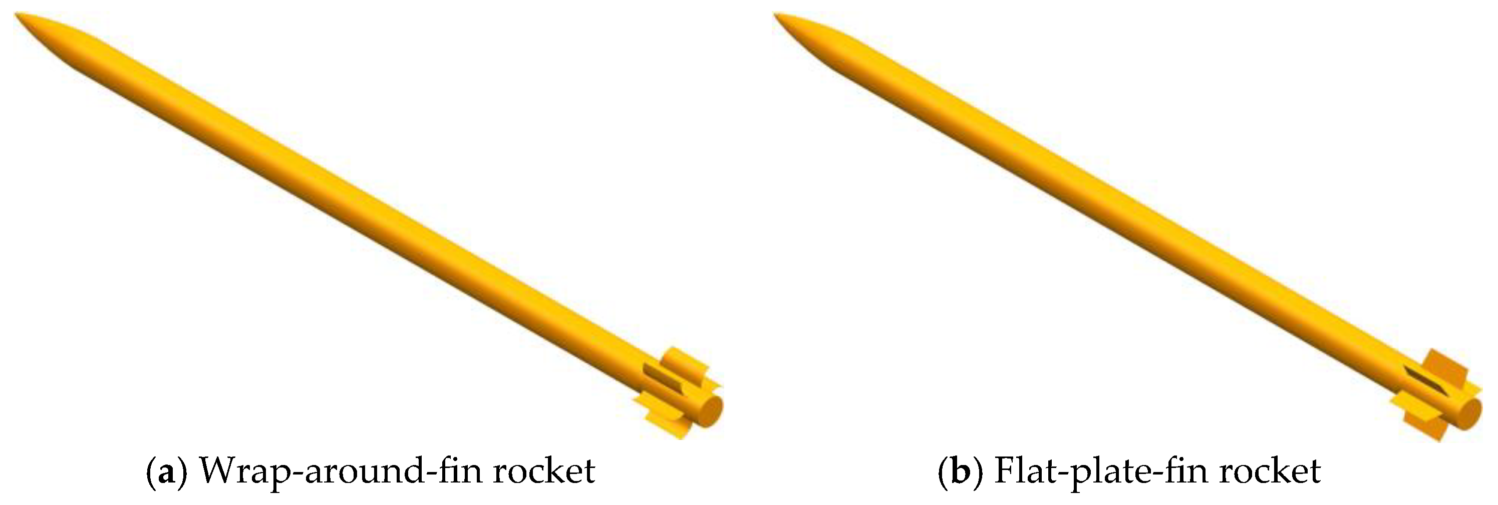
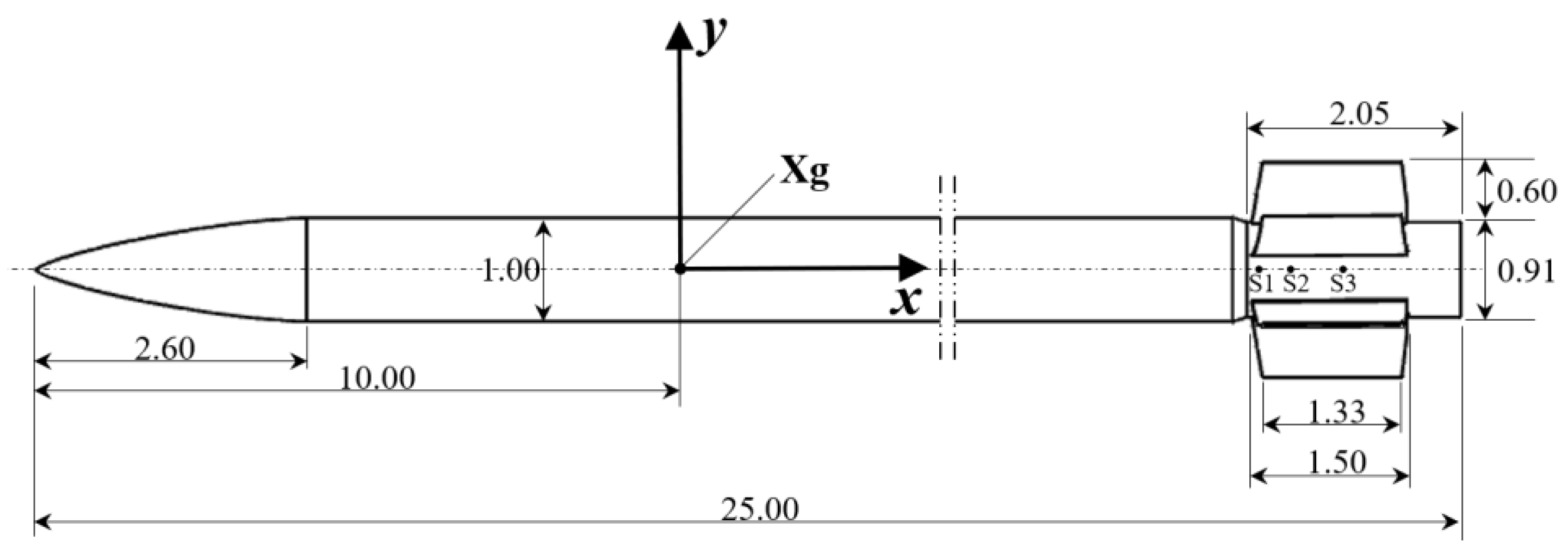
Figure 2 shows the geometric parameters of the rocket, as well as the coordinate system. The longitudinal axis of the rocket is the axis of rotation and coincides with the X-axis. In this study, a positive rotation rate is defined as pointing towards the positive X-axis direction, meaning that the rotation rate is positive when the convex side of the wrap-around fin faces the wind and negative otherwise. The original body’s fineness ratio is L/D = 25, with a reference length Lref = 7.65 m and reference area Sref = 0.0707 m2. The ratio of the distance from the center of mass to the head vertex to the length of the projectile is xg/L = 0.396. In the study, a flat-plate fin rocket with the same projected area and shape as shown in Figure 3 was set as a control for the wrap-around-fin rocket.
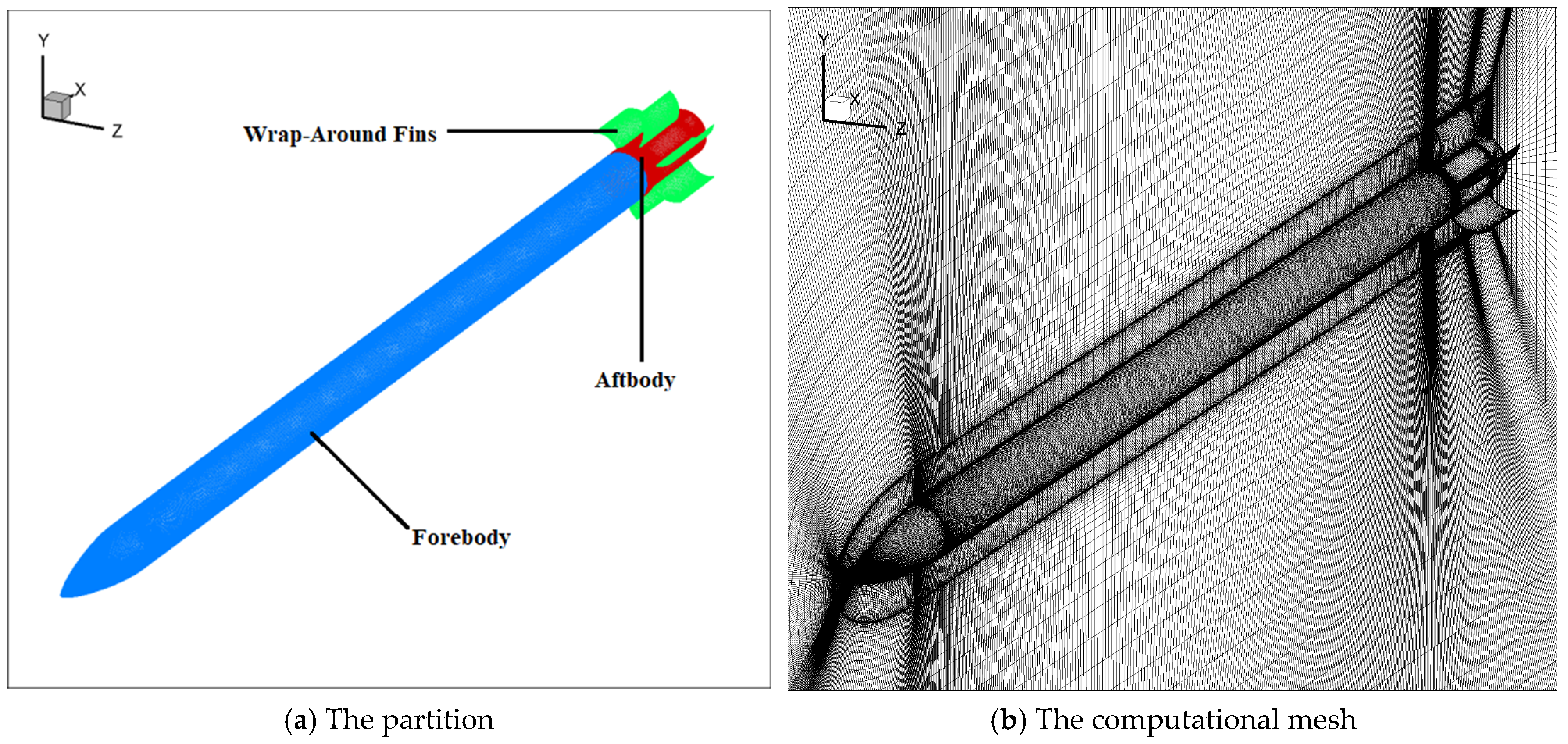
Figure 4 shows the schematic of the rocket’s partition and computational mesh. To facilitate the analysis of the force characteristics of different parts of the rocket, the blue section is defined as the forebody, the red section as the aftbody (with some contraction in the tail section), and the green section as the six fins. The computational grid is composed of hexahedral structured grids, ensuring that the first layer grid height meets y+ < 1, and the wall grid growth rate is maintained below 1.1. The projectile surface has 360 longitudinal and 200 circular grid nodes, with 60 nodes in the spanwise direction, totaling approximately 9.72 million grid cells.

3.2. Computational Conditions

The grid boundaries in the front and circumferential direction of the rocket are set to free-stream boundary conditions, the grid boundary in the rear of the rocket is the pressure outlet, and the rocket surface is set to a no-slip adiabatic boundary condition. Free-stream parameters are set according to the atmosphere at a height of 10 km, with the incoming static pressure of p = 26,500 Pa and a static temperature of T = 233 K. The numerical computation includes Mach numbers of Ma = 1.5, 2.5, 3.5, 4.5 and angles of attack α = 2°, 4°, 6°, 8°, 10°. The dimensionless rotation speed Ω equals the equilibrium rotation speed at different Mach numbers, specifically Ω = 0.00688, 0.00455, 0.006, 0.00911.

3.3. Validation of Unsteady Numerical Methods

3.3.1. Validation of Rotation Method

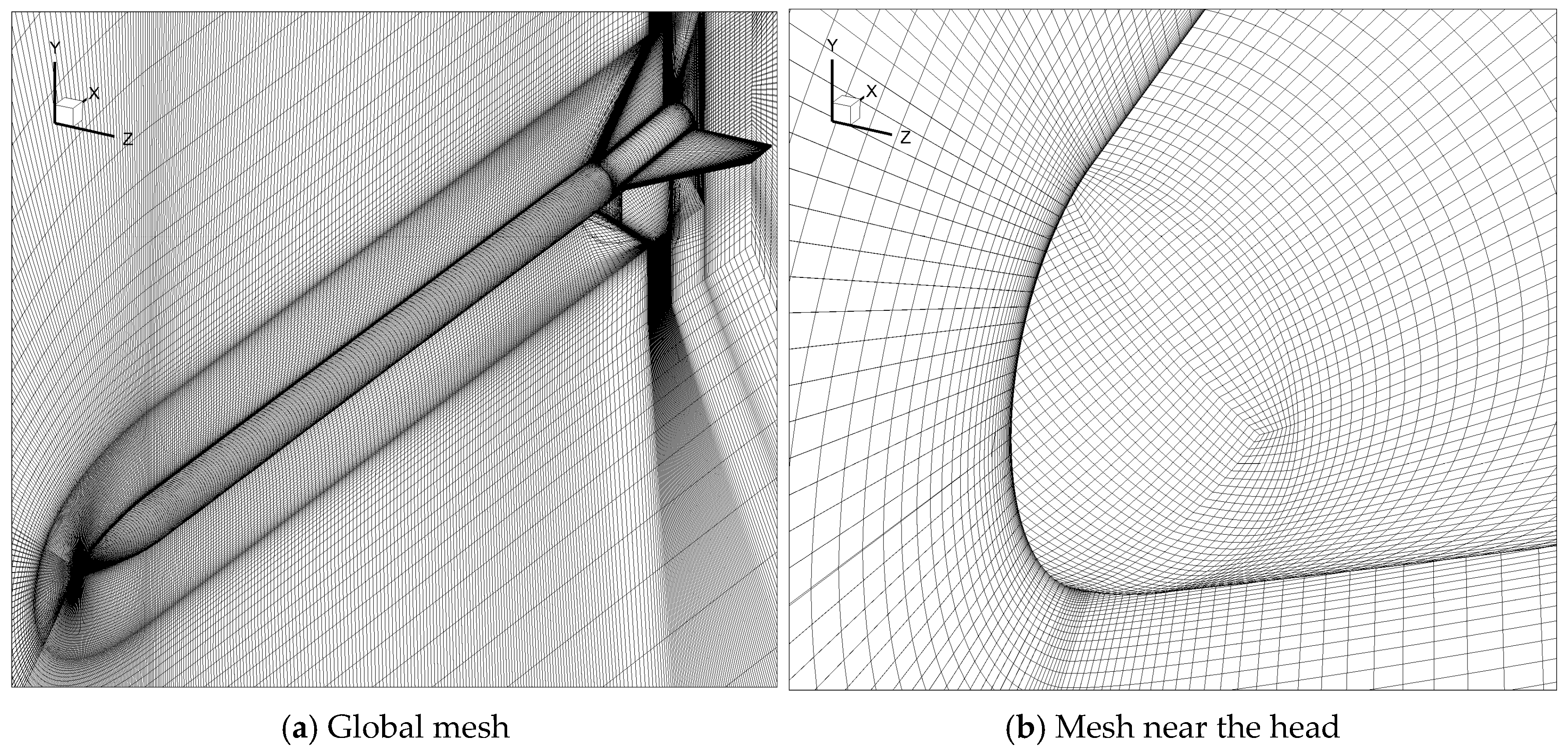
Figure 5 shows the schematic diagram of the large fineness ratio rocket Apache [20], with a diameter D = 0.0508 m. The Apache consists of a 3D arch-shaped head, a cylindrical projectile body of 21.88 D, and four fins with an installation angle of 2°. The fineness ratio of the rocket is L/D = 24.88. The Reynolds number is ReD = 1.54 × 10⁷, Mach number Ma = 3.0, angle of attack α = 0°, 4°, 8°, 12°, and non-dimensional rotation rate Ω = 0.011. The reference length Lref = 7.65 m, reference area Sref = 0.0707 m2, and the distance of the center of gravity from the head vertex is xg = 0.69 m. The grid is shown in Figure 6. The height of the first grid layer at the wall is 2 × 10⁻⁶ m, ensuring the non-dimensional distance y+ ≤ 1. The boundary conditions are the same as those for the rocket in Section 3.1.
The rotational motion of the aircraft primarily affects its lateral aerodynamic characteristics; thus, the influence on the longitudinal aerodynamic characteristics can be neglected. During the validation of the numerical method, the calculated results of out-of-plane force/moment were compared with the experimental data [20]. Figure 7 compares simulations and experiments of the out-of-plane force/moment for Apache. The results show that within 8° of the angle of attack, the computational results agree well with the experimental data. As the angle of attack increases, the discrepancy between the two grows, but this error is still acceptable. Due to the large fineness ratio of the rocket body and the complexity of the axial flow field, the current method has limited accuracy in capturing effects such as boundary layer transition, flow separation, and dissipation of separation vortices at higher angles of attack; therefore, to ensure the reliability of the computational results, the angle of attack range in this study is limited to 0° < α < 12°.

3.3.2. Validation of Grid Independence

Subsequently, grid and time-step independence were verified. Grid independence verification was conducted using the Apache shape. Three sets of grids with different numbers were chosen for grid independence verification at an angle of attack α = 12.0°, and the specific parameters of the grid on the surface are shown in Table 1.
Table 2 shows the relative percentage errors of the mean values of normal force, side force, pitching moment, and yawing moment coefficients. According to Table 2, the relative errors of normal force and pitching moment for the Coarse and Moderate grids compared to the Fine grid are within 0.3%, while the relative errors of side force and yawing moment are within 7%. Considering both computational accuracy and resource factors, the Moderate grid was used for calculations in subsequent research.

3.3.3. Validation of Time-Step Independence

Time-step independence verification was conducted using the shape in Figure 3. The calculation conditions are Ma = 3.5, α = 10°, and non-dimensional rotation rate Ω = 0.006. Three different time steps were used for the calculations, where the rotation period is t = 2π/ω. Figure 8 shows the results of time step independence validation. The relative error between ∆t1 and ∆t3 is within 4%, while the relative error between ∆t2 and ∆t3 is within 0.5%; therefore, ∆t2 can be considered to satisfy the criterion of time-step independence.
In conclusion, the numerical method used in this study meets the aerodynamic force calculation requirements for a large fineness ratio rotating rocket at small angles of attack. In future calculations, the Moderate grid set and a time step ∆t2 will be utilized.

4. Results and Discussion

4.1. Variation in Aerodynamic Characteristics with Angle of Attack and Mach Number

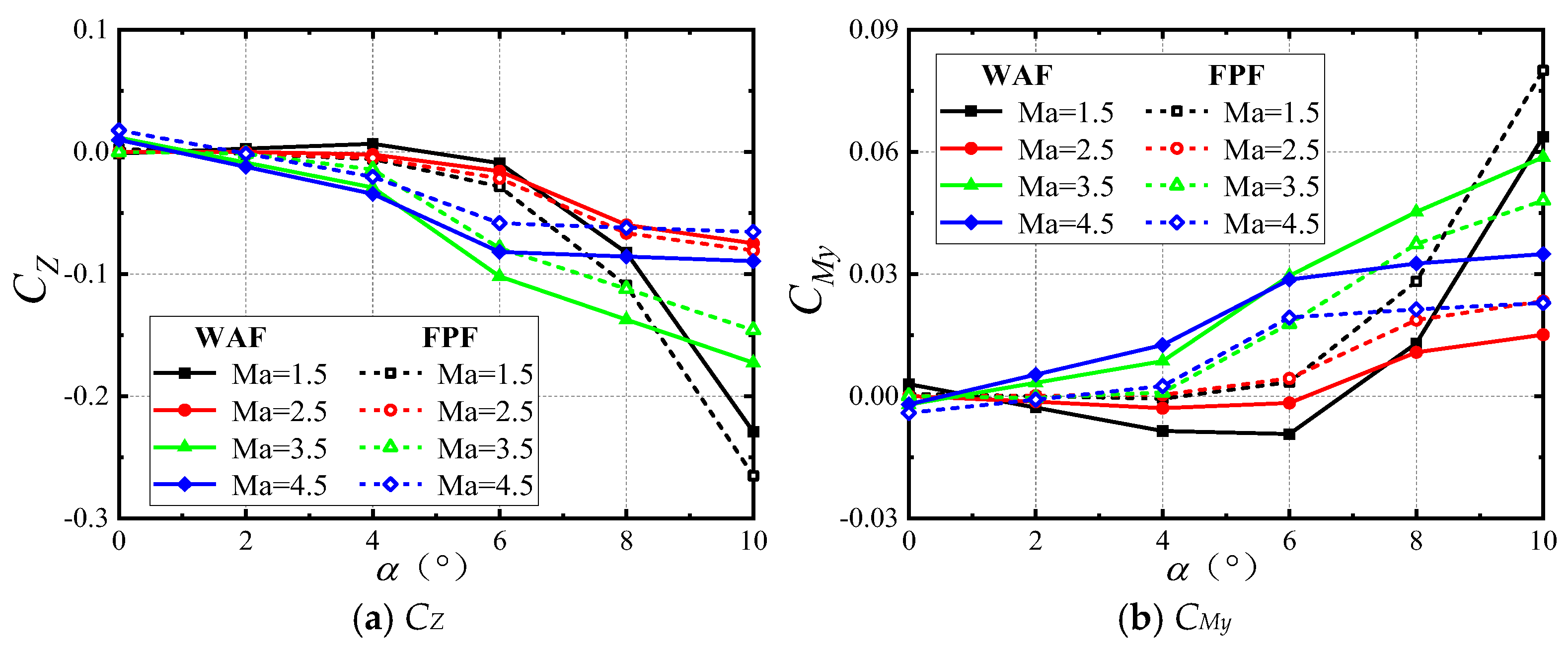
Figure 9 illustrates the curves of time-averaged out-of-plane force and moment coefficients with angle of attack for rockets at Ma = 1.5, 2.5, 3.5, and 4.5. The figures show that the trends of time-averaged out-of-plane force and moment coefficients for wrap-around-fin and flat-fin configurations are similar, but with some quantitative differences. The time-averaged out-of-plane force and moment coefficients of wrap-around-fin and flat-fin rotating rockets exhibit approximately linear changes within the range of 0° < α < 4°. As the angle of attack increases, the out-of-plane force and moment coefficients demonstrate nonlinear trends. At Ma = 1.5, there is a near-exponential growth trend for the out-of-plane force and moment, while at other Mach numbers, the increase in the out-of-plane force and moment coefficients is relatively slow. Comparing the curves at different Mach numbers reveals that at Ma = 1.5, the wrap-around-fin configuration exhibits a reversal in the time-averaged out-of-plane force and moment with increasing angle of attack, a phenomenon that disappears as the Mach number increases.
Figure 10 shows the curves of time-averaged out-of-plane force and moment coefficients with respect to angle of attack for the components of the wrap-around-fin and flat-fin rockets at Ma = 1.5 and 3.5. Analysis of the out-of-plane moment coefficient curve of the WAF rocket shows that when Ma = 1.5, the time-averaged out-of-plane moment of the forebody is very small within the range of 0° < α < 4°, while that of the aftbody is significant. Although the tail fin’s out-of-plane moment partially offsets the aftbody’s out-of-plane moment, the total value still surpasses that of the forebody, resulting in a negative total out-of-plane moment for the entire rocket. As the angle of attack increases, the time-averaged out-of-plane moment of the forebody rapidly increases. By α = 8°, the sum of the time-averaged out-of-plane moments of the forebody and the tail fin exceeds that of the aftbody, thereby changing the total time-averaged out-of-plane moment from negative to positive. At a high Mach number of Ma = 3.5, the angle between the wing leading-edge shock wave and the tail fin decreases. This reduction in angle weakens the aerodynamic interference of the tail fin on the aftbody, leading to a decrease in the time-averaged out-of-plane moment coefficient of the aftbody. At this point, the time-averaged out-of-plane moment of the tail fin is maximized, ensuring that the total time-averaged out-of-plane moment remains positive and prevents any reversal phenomenon. The forebody of the rocket in the flat-fin configuration is the same as that in the wrap-around-fin configuration, thus inducing the same out-of-plane moment due to rotation. However, the differences in the out-of-plane moments of the aftbody and the tail fin section will lead to variations in the yawing moment characteristics of the entire rocket. Within the range of 0° < α < 6°, the magnitudes of the out-of-plane moments of the aftbody and tail fin of the flat-fin configuration are small and opposite in direction. As a result, after the moments of the aftbody and tail fin cancel each other, the magnitude is smaller than that of the forebody, leading to a positive total out-of-plane moment. When α > 6°, both the aftbody and tail fin have out-of-plane forces in the same direction as the forebody, resulting in a positive total out-of-plane moment without any reversal.
In conclusion, the differences in the time-averaged out-of-plane force and moment between the wrap-around-fin and flat-fin configurations mainly stem from the tail fin and aftbody. Compared with the flat fin, at low Mach numbers, the wrap-around-fin configuration exhibits stronger aerodynamic interference on the aftbody, potentially causing the combined out-of-plane moment of the aftbody and tail fin to oppose that of the forebody, leading to a reversal of the total out-of-plane moment. As the Mach number increases, the aerodynamic interference of the tail fin on the aftbody diminishes, eliminating the reversal phenomenon.

4.2. The Effect of Rotational Motion on Aerodynamic Characteristics

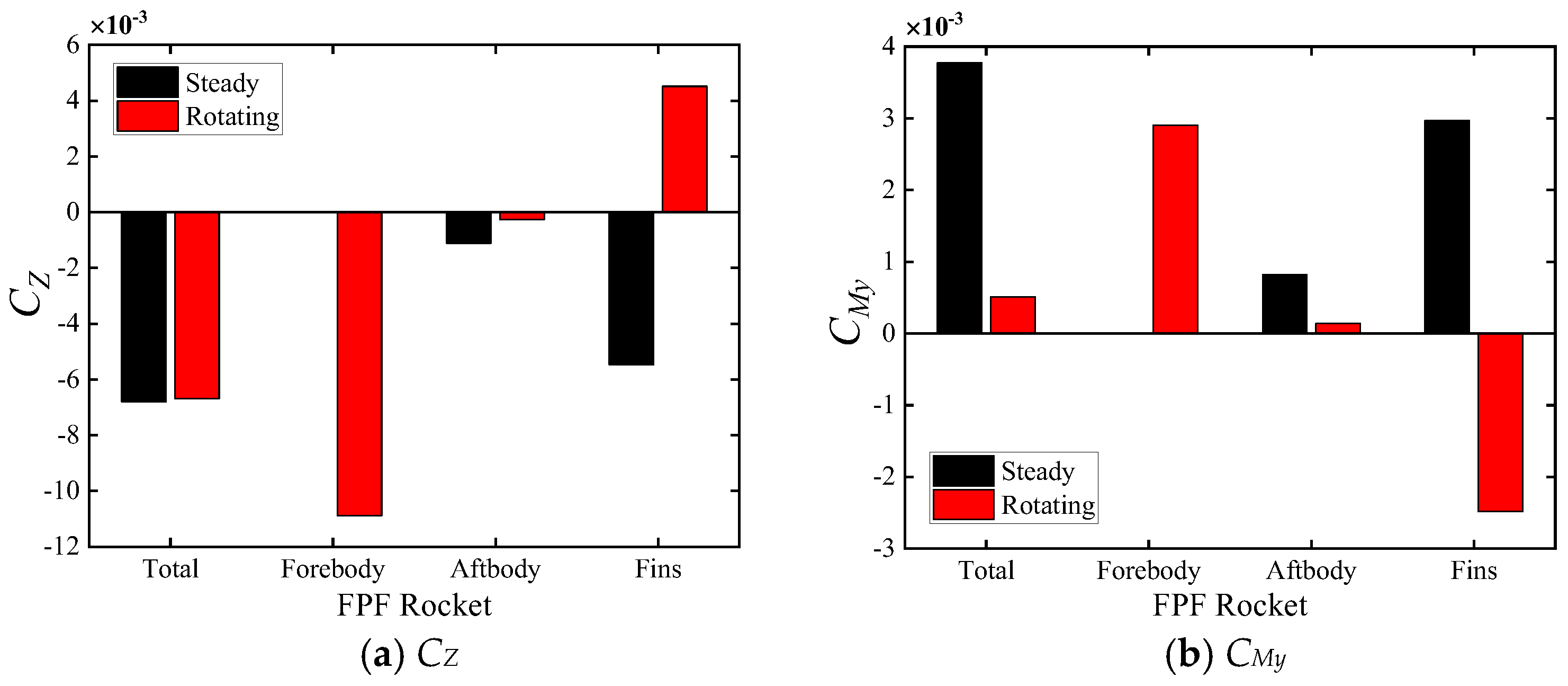
To study the effect of rotating motion on the side force and yawing moment characteristics of the rocket, steady and unsteady calculations were performed for rockets with flat and wrap-around fins. Figure 11 and Figure 12 show the time-averaged side force and yawing moment of flat-fin and wrap-around-fin rockets at Ma = 3.5 and α = 4°. The time-averaged values obtained from steady-state calculations are fitted using a Fourier series based on steady aerodynamic characteristics at 20 evenly spaced positions with a roll angle of 0° to 60°. The time-averaged values from unsteady calculations are obtained by fitting a Fourier series to the aerodynamic characteristics within one roll cycle.
Based on Figure 11, for the FPF rocket, rotational motion has a negligible effect on the total side force of the rocket, but it significantly reduces the rocket’s total yawing moment. With a large fineness ratio, the rotational motion causes the side force on the forebody to change from zero to non-zero. Compared with other areas, the magnitude of the yawing moment on the forebody is significant, leading to a substantial forward shift in the lateral aerodynamic center. This results in a reduction in the total yawing moment of the rocket, possibly even causing a change in orders of magnitude. For the tail fin, the side force when not rotating is determined by the fin’s mounting angle. When rotating, the side force is determined by the effective angle of attack obtained by adding the flight angle of attack, wing mounting angle, rotation rate-induced angle of attack, and wing–body interference effects, leading to a reversal compared with when not rotating. The side force and yawing moment on the aftbody are both very small, resulting in minimal impact on the total aerodynamic characteristics of the rocket.
Based on Figure 12, for the WAF rocket, the rotational motion results in an increase of approximately 24% in the total side force and a decrease of approximately 10% in the total yawing moment. Overall, the effect is not significant. The side force and yawing moment on the forebody are the same as those of the flat-fin rocket; however, they are no longer the dominant factors of the total side force and yawing moment. The forces on the wrap-around fins in a steady state are determined by the asymmetry of their shape, and the rotation-induced effective angle of attack slightly weakens the side force caused by the asymmetric configuration of the wrap-around fins. As a result of the aerodynamic interference from the wrap-around fin, the aftbody also generates significant side force and yawing moment. Moreover, the effects of these forces and moments are opposite to the direction of the forces on the wrap-around fin itself. For the WAF rocket, the side force and yawing moment on the wrap-around fin and the aftbody of the rocket dominate the total side force and yawing moment.

4.3. Typical Flow Mechanisms Induced by Flat Fins and Wrap-Around Fins

In this section, an analysis of the flow characteristics around the rockets is conducted. Figure 13 shows the variation curves of the side forces on the aftbody and fins with roll angle at Ma = 3.5, α = 4°, and Ω = 0.006. The side force coefficient curve induced by the six fins exhibits six oscillation cycles. The phase angles of the force variations on the rear body and fins are the same. Additionally, there are significant differences in the side force characteristics between the two rocket shapes. Therefore, a flow analysis is conducted at a roll angle of approximately 73°, where the side force reaches its extremum. Specific details can be found in Figures S1 and S2 of the Supplementary Materials.
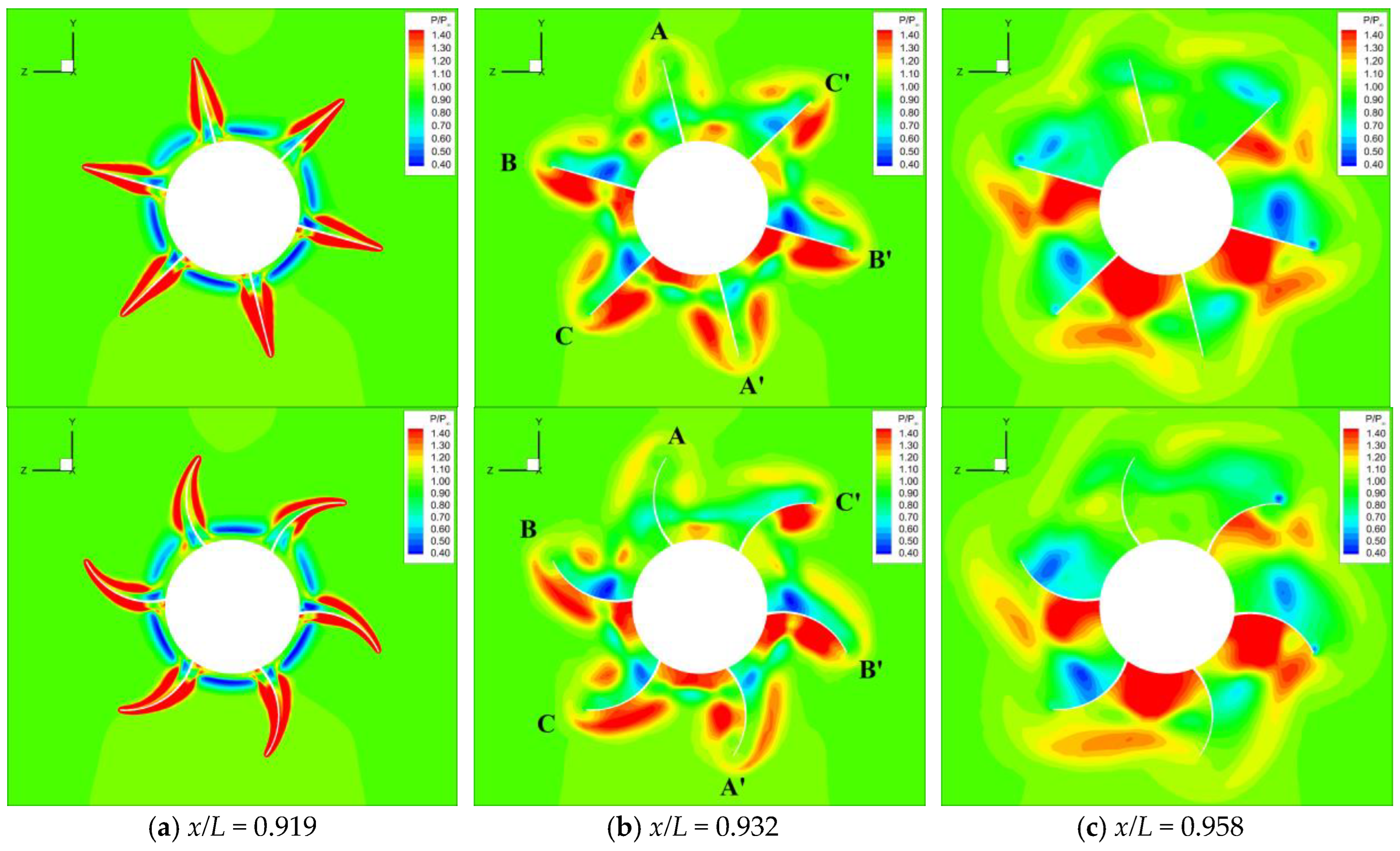
Figure 14 compares the dimensionless pressure coefficient distribution contour maps of the two tail fin configurations in three sections. The section positions have been provided in Figure 2 (S1~S3). Figure 14a shows that due to the curvature of the wrap-around fin, the shock wave surface at its leading edge will also exhibit a certain curvature. In Figure 14b, for the flat-fin configuration, Fin B and Fin B’ generate -Z-direction side force, Fin C and Fin C’ produce + Z-direction side force, while the contribution of Fin A and Fin A’ to the forces on the tail fin is not significant. Since the angle of attack, rotation rate, and roll angle are relatively small at this time, there is a certain symmetry about A-A’ in the flow field near the flat fin, resulting in lower values for the side force and yawing moment generated on the flat fin. For the wrap-around fin configuration, the pressure distribution near the tail fin is very similar to that of the flat-fin configuration, but the flow field is entirely asymmetric.
Comparing the flow fields of the two tail fin configurations reveals that following the shock waves on the convex surface of the wrap-around fin, the flow area and the air expansion speed increase, and the pressure decreases compared with the flat-fin configuration; after the concave surface shock waves, the flow area decreases and the leading edge shock waves converge, resulting in higher pressure near the wing surface compared with the flat-fin configuration. Therefore, the greater pressure difference between the concave and convex surfaces of the wrap-around fin results in greater aerodynamic forces. Figure 14c shows that as the airflow progresses rearward, the impact of the wrap-around fin on the leading edge shock wave continues to be influential, further increasing the differences compared with the flow field of the flat fin. In conclusion, the curvature of the wrap-around fin increases the asymmetry of the flow field near the tail fin, significantly increasing the side force and yawing moment acting on the wrap-around fin.

4.4. Influence of the Aspect Ratio of the Tail Fin on Aerodynamic Characteristics

Numerical calculations in this section focused on the flow field and aerodynamic features of wrap-around-fin rocket shapes with aspect ratios of 0.236, 0.301, and 0.405. The study varied the wrap-around-fin length S and chord length C along the normal projected area of the tail fin while maintaining consistency to analyze the impact of aspect ratio on the out-of-plane force and moment characteristics of the wrap-around-fin rocket. Figure 15 depicts schematic diagrams of wrap-around fins with varying aspect ratios.
Figure 16 presents bar charts of the time-averaged out-of-plane force and moment characteristics of three tail fin aspect ratio shapes. The graph shows that as the aspect ratio increases from 0.236 to 0.405, the total out-of-plane force coefficient increases by approximately 40%, and the total out-of-plane moment coefficient increases by approximately 70.3%. Although the time-averaged out-of-plane force of the forebody contributes significantly to the total out-of-plane force, the out-of-plane moments on the fore and aft bodies cancel each other out due to their locations relative to the center of mass, resulting in a relatively small contribution of the forebody to the out-of-plane moment. The out-of-plane force and moment on the tail fin increase by approximately 160% with the change in aspect ratio, which is the dominant factor causing the changes in total out-of-plane force and moment.
Surface pressure coefficient distribution curves and flow field cloud maps were plotted at typical moments for analysis. Please refer to Figures S3–S5 in the Supplementary Materials. The results indicate, the main reasons for the increase in out-of-plane force and moment with an increase in the aspect ratio of the tail fin are twofold: firstly, after the aspect ratio increases, the flow compression and expansion effects caused by the curvature of the concave and convex surfaces are enhanced, leading to an increase in static additional angle of attack; secondly, the increase in length results in a higher rotation line speed at the wingtip, providing a larger rotational additional angle of attack at the wingtip.
Figure 17 shows the time-averaged normal force and pitching moment coefficients of shapes with different aspect ratios. As the aspect ratio increases from 0.263 to 0.405, the rocket experiences an increase of approximately 3.8% and 12.4% in the time-averaged normal force and pitching moment coefficients, respectively, with little change in longitudinal aerodynamic characteristics. Due to the significant increase in the out-of-plane moment coefficient with increasing aspect ratio, the larger the aspect ratio, the greater the absolute value of the ratio between the out-of-plane moment and pitching moment coefficients, leading to an increased proportion of destabilizing moment, making the rocket more prone to flight instability.

4.5. Influence of the Fineness Ratio of the Rocket Body on Aerodynamic Characteristics

Figure 18 shows the curves of the time-averaged out-of-plane force and out-of-plane moment of the rocket with Ma = 3.5 and α = 4° as functions of the fineness ratio of the rocket body. At L/D = 15, the contribution of the forebody to the time-averaged out-of-plane force of the entire rocket is only 12%, and its contribution to the time-averaged out-of-plane moment is approximately 8%, with the aftbody and fin dominating the time-averaged out-of-plane force and moment; conversely, at L/D = 25, the contribution of the forebody to the time-averaged out-of-plane force of the entire rocket reaches approximately 65%, and its contribution to the time-averaged out-of-plane moment increases to 50%. If the fineness ratio is increased further, the forebody may dominate the time-averaged out-of-plane force and moment of the entire rocket.
The distribution along the rocket axis of the time-averaged out-of-plane force and moment coefficients for shapes with different fineness ratios has been analyzed. Please refer to Figures S6–S8 in the Supplementary Materials. The analysis results indicate that the changes in out-of-plane force and moment are primarily generated by the aftbody behind the center of gravity. Additionally, with an increase in the rocket’s fineness ratio, the absolute value of the ratio between the out-of-plane moment and pitching moment coefficients increases, indicating a larger proportion of destabilizing moment, making the rocket more prone to flight instability.

4.6. Stability Analysis of Angular Motion

Due to the small proportion of the tail fin’s weight in the total weight of the rocket, this study only considers the influence of changes in the fineness ratio of the forebody on the structural parameters, neglecting the effects of tail fin shape and tail fin aspect ratio on the rocket’s mass. Table 3 provides specific structural parameters for shapes with different fineness ratios. The JH-1 shape represents the original large fineness ratio wrap-around-fin shape, the PZ shape represents its counterpart flat-fin shape, and the JH-2 and JH-3 shapes represent wrap-around-fin shapes with fineness ratios of 20 and 15, respectively.
Figure 19 shows the variation curves of the pitching moment coefficients for different shapes within one pitching cycle. The tail fin shape, fineness ratio of the body, and aspect ratio of the tail fin all have specific effects on the pitching moment during the pitching vibration of the rocket: the tail fin shape and aspect ratio have a relatively minor impact, while the effect of the body’s fineness ratio is more pronounced.
The aerodynamic coefficients and their derivatives at zero angle of attack are summarized in Table 4. A and B represent the original flat-fin and wrap-around-fin shapes, and B1–B4 correspond to the results at different Mach numbers; C and D represent shapes with different aspect ratios, neglecting the impact of aspect ratio changes on mass distribution, hence sharing the structural parameters with A and B; E and F represent shapes with different body fineness ratios; Shapes C–F are all wrap-around-fin configurations. Equations (18) and (20) can be used as criteria for angular motion stability.
Rockets experience complex disturbances during flight, leading to additional angles of attack and sideslip angles. For wrap-around-fin rockets with large fineness ratios, at small angles of attack, the aerodynamic characteristics vary approximately linearly with the angle of attack, allowing the use of linearized angular motion equations for stability analysis. As the angle of attack increases, the aerodynamic characteristics exhibit a nonlinear trend, making the linearized angular motion equations inapplicable. Hence, this study analyzed the angular motion stability of the rocket with an initial angle of attack of zero and an initial disturbance angular velocity of Δ ˙ = α ˙ + i β ˙ = 0.05 + i 0.05 (deg/s) based on the linearized angular motion equations.

4.6.1. Influence of Tail Fin Shapes

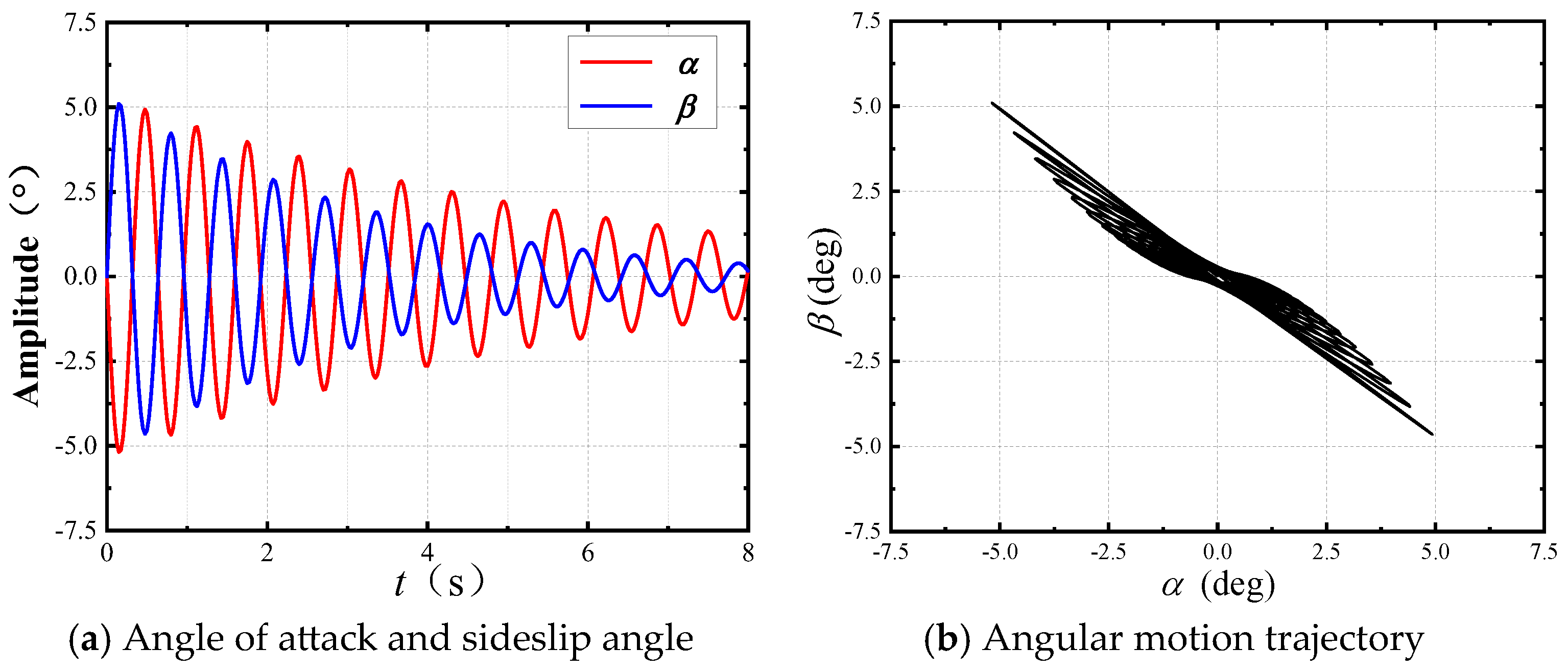
Figure 20 and Figure 21 show the dynamic angle of attack and sideslip angle responses, as well as the angular motion trajectories of the flat-fin rocket and wrap-around-fin rocket (Cases A and B3) at Ma = 3.5. For a given initial disturbance, the angle of attack and sideslip angle of the flat-fin rocket both converge to zero, and the angular motion trajectory rapidly contracts towards zero; conversely, the angle of attack and sideslip angle of the wrap-around-fin rocket diverge, and the angular motion trajectory gradually moves away from zero during motion.
The aerodynamic data in Cases A and B3 from Table 4 indicate that the differences in axial force coefficients and longitudinal aerodynamic parameter derivatives between the flat-fin rocket and the WAF rocket are minimal, although the differences in pitch damping moment coefficient are slightly larger, but still within 10%; thus, the magnitude of the yawing moment coefficient derivative C my α , ω ¯ is the key factor determining the stability of the rocket. Table 5 provides the stability conditions and results of angular motion stability for the two configurations mentioned above. The differences in intrinsic physical parameters between flat-fin and wrap-around-fin shapes were neglected when analyzing stability. Due to the small difference in aerodynamic characteristics other than the lateral aerodynamic properties of the two shapes, their stability regions are very close. The C my α , ω ¯ for the flat-fin rocket meets the stability conditions, resulting in converging angular motion; however, the C my α , ω ¯ for the wrap-around-fin rocket is one order of magnitude larger than that of the flat-fin rocket, surpassing the stability boundary and causing divergent angular motion.

4.6.2. Influence of the Fin’s Aspect Ratio

Figure 22 and Figure 23 show the dynamic angle of attack and sideslip angle responses, as well as the angular motion trajectories for Cases C and D. According to Figure 22a, at an aspect ratio of 0.301, the rocket’s angle of attack and sideslip angle response curves oscillate significantly over a large range and exhibit a divergent trend. The phase trajectory in Figure 22b is similar to that in Figure 21b, but with a slow divergence speed, near the critical state transitioning from divergence to convergence. Figure 23 shows that as the aspect ratio further decreases to 0.236, the rocket’s angle of attack and sideslip angle converge towards zero, transforming the originally divergent angular motion into convergence; however, it takes a relatively long time to converge back to the initial position.
According to the data for Cases B3, C, and D (Table 4), the rocket’s C x and C y α decrease as the aspect ratio decreases, while the absolute value of m zz significantly increases. Equation (21) shows that variations in C x and m zz lead to an enlargement of the stability region, while variations in C y α result in a reduction in the stability region. Table 6 presents the angular motion stability conditions and stability assessment results for shapes with different aspect ratios. As the tail fin aspect ratio decreases to 0.301, the substantial change in C y α plays a leading role, and as the aspect ratio decreases further, the change in C y α becomes minimal, thus C x and m zz take on a dominant role. Compared with Case B3, the C my α , ω ¯ of Case C decreased by 30%, but the right stability boundary simultaneously decreased by 25%; therefore, the C my α , ω ¯ of Case C still lies outside the stability domain, failing to meet the conditions for angular motion stability, resulting in angular divergence. As the aspect ratio decreases to 0.236, the right stability boundary of Case D increases, while C my α , ω ¯ decreases further, meeting the conditions for stable flight, thus leading to angular convergence.
As the aspect ratio changes, both longitudinal and lateral aerodynamic parameters undergo significant changes, leading to a lack of a direct intuitive relationship between the range of angular motion stability boundaries and the aspect ratio changes. Therefore, the angular motion stability of shapes with different aspect ratios may require individual analysis. Overall, although both stabilizing moment and out-of-plane moment decrease as the aspect ratio decreases, the out-of-plane moment changes more rapidly; in other words, the ratio of stabilizing moment to out-of-plane moment increases with decreasing aspect ratio, favoring stable flight.

4.6.3. Influence of the Body’s Fineness Ratio

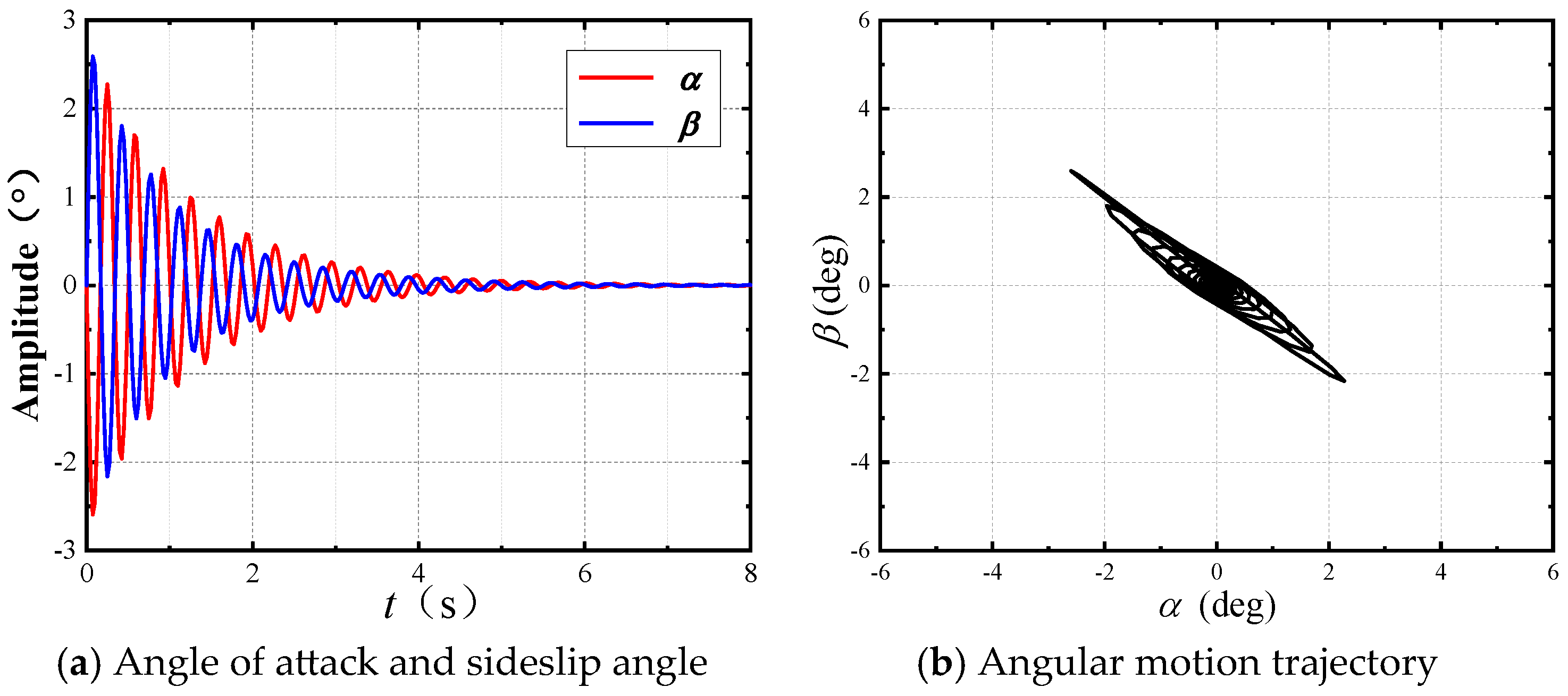
Figure 24 and Figure 25 present the dynamic responses of angle of attack and sideslip angle, as well as the angular motion trajectories of Case E and Case F. In Case E, the values of angle of attack and sideslip angle generated by the initial angular velocity disturbance gradually decrease, and the rocket’s phase trajectory gradually returns to the vicinity of the original position. In Case F, the convergence speed of the angle of attack and sideslip angle generated by the initial disturbance is very fast, and the trajectory converges to zero within a short period. Compared with Case B3 in Figure 21, it can be seen that as the fineness ratio decreases, the angular motion of the wrap-around-fin rocket changes from divergence to convergence, with an accelerated convergence speed.
Table 7 presents the angular motion stability conditions and stability assessment results for shapes with different forebody fineness ratios. According to the table, the angular motion stability domain of the rocket significantly increases as the forebody fineness ratio decreases. The data in Table 3 indicate that as the fineness ratio decreases, the values of Ix/Iy and Ix/mL2 increase, resulting in a greater influence of the aerodynamic coefficients on the size of the stability region. Data for Cases B3, E, and F in Table 4 show that as the fineness ratio of the body decreases, the changes in C x and C y α are relatively small, while m zz significantly increases, leading to an enlargement of the stability region. Furthermore, the rocket’s C mz α increases slightly, while C my α , ω ¯ decreases by approximately 30%. At the same time, the pitch-damping moment coefficient of the rocket increases fourfold, leading to a higher ratio of stabilizing moment to out-of-plane moment, making flight instability less likely to occur.

4.6.4. Influence of Mach Numbers

Figure 26 shows the dynamic responses of angle of attack and sideslip angle at different Mach numbers, corresponding to Cases B1, B2, and B4 in Table 4. At Ma = 1.5 and Ma = 2.5, the angles of attack and sideslip generated by initial angular velocity disturbances gradually decrease. Decay is faster at Ma = 1.5, with sideslip converging more quickly than the angle of attack; however, the decay is slower at Ma = 2.5, making it difficult to converge to zero within a short period. At Ma = 4.5, the angles of attack and sideslip generated by initial angular velocity disturbances gradually increase and tend to diverge. A comparison with Figure 21a shows that the rates of increase in angle of attack and sideslip are faster, potentially leading to flight instability within a relatively short time.
Figure 27 shows the angular motion phase trajectories of the wrap-around-fin rocket at different Mach numbers. At Ma = 1.5 and Ma = 2.5, the initial disturbance angular velocity causes the rocket to generate angles of attack and sideslip, which then gradually decay towards the initial state. For Ma = 1.5, the range of complex angles of attack rapidly decreases over time, indicating stable angular motion, while for Ma = 2.5, although the complex angle of attack shows a converging trend, the disturbance decay rate is very small, suggesting that the rocket’s angular motion at Ma = 2.5 is near the critical state between convergence and divergence. Combining Figure 27c with Figure 21b reveals that at Ma = 3.5 and Ma = 4.5, the radius of the complex angle curves gradually increases, signifying a divergence in angular motion, with Ma = 4.5 demonstrating a faster divergence speed, suggesting a greater distance from the convergence boundary at Ma = 4.5.
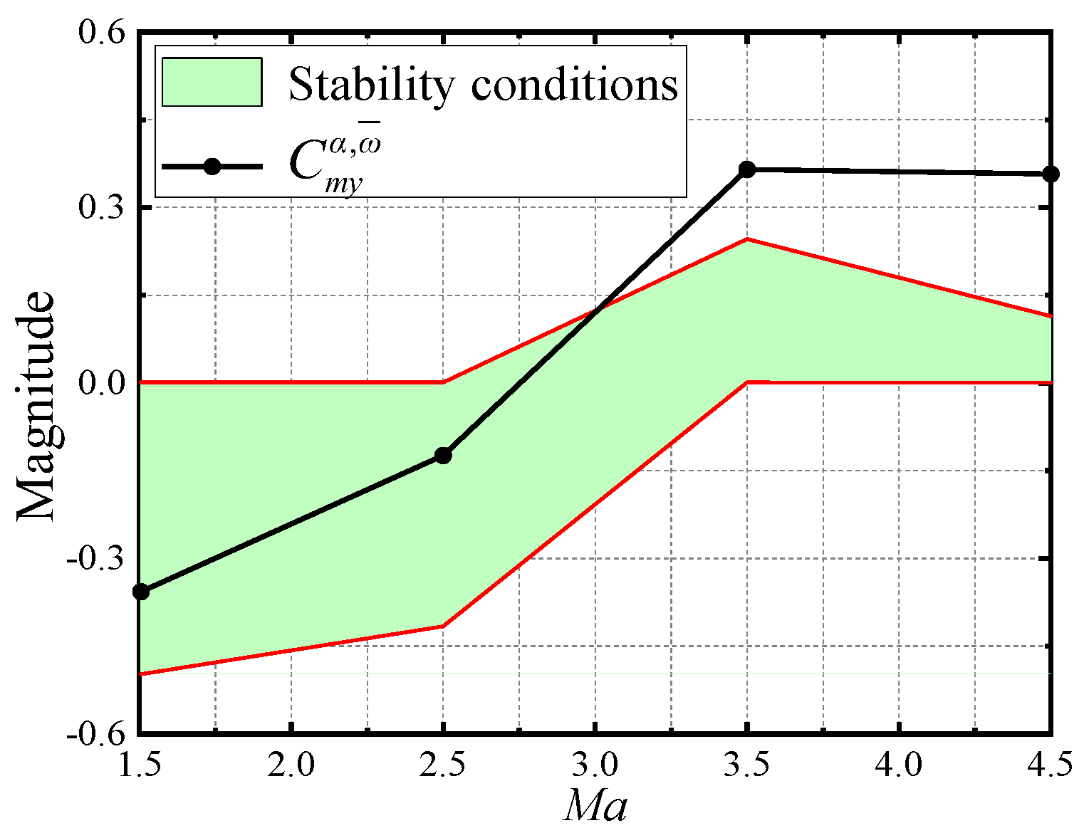
Table 8 presents the stability analysis results of the wrap-around-fin rocket at different Mach numbers based on Equations (18) and (20), and the angular motion stability region and yawing moment coefficient derivative distribution diagram in Figure 28 were plotted using the data in the table. At lower Mach numbers, Sd > 0, and the stability region is distributed in the negative axis direction, while at higher Mach numbers, Sd < 0, and the stability region is distributed in the positive axis direction. Figure 28 shows that at low Mach numbers, the stability region is large, reducing the likelihood of flight instability; however, as the Mach number increases, the stability region significantly shrinks, posing challenges for stable flight. The angular motion stability region becomes very small and C my α , ω ¯ deviates from the stable region when the Mach number reaches 4.5; thus, the angular motion diverges within a short period, which is consistent with the analysis results shown in Figure 26 and Figure 27.

5. Conclusions

This study analyzed the aerodynamic characteristics and flow field structure of a large fineness ratio rotating wrap-around-fin rocket by solving the URANS equations. The side force and moment coefficients obtained from numerical calculations and experiments were compared to validate the reliability of the numerical method. The study derived the conditions necessary for the yawing moment coefficient to ensure stability during angular motion by incorporating the equations of angular motion. By varying the tail fin shape, tail fin aspect ratio, and body fineness ratio, the study investigated the effects of geometry and Mach number on the stability of the rotating wrap-around-fin rocket’s angular motion. The following conclusions were drawn:
(1)
The differences in time-averaged out-of-plane force and moment between the wrap-around-fin and flat-fin rockets primarily stem from the tail fin and aftbody. The static out-of-plane force and moment generated by the non-planar symmetry of the wrap-around-fin configuration dominate the overall out-of-plane force and moment, which may play a decisive role in flight stability under critical conditions.
(2)
The concave flow passage of the wrap-around fin contracts, maintaining high pressure due to the convergence of the shock wave, while the convex flow passage expands, causing airflow acceleration and pressure reduction, resulting in a strong asymmetry in pressure distribution on both sides of the wing that also disturbs the body, leading to significant side force and yawing moment characteristics.
(3)
As the aspect ratio of the tail fin decreases, the out-of-plane force and moment of the tail fin and aftbody significantly decrease, leading to a reduction in the overall out-of-plane force and moment coefficients; the pitching moment coefficient decreases slowly with the decrease in tail fin aspect ratio, resulting in a decrease in the ratio of unstable moment to stable moment, making the rocket more likely to maintain stable flight.
(4)
As the fineness ratio of the body decreases, the out-of-plane force and moment coefficients of the forebody significantly decrease, leading to a reduction in the overall out-of-plane force and moment coefficients; the pitching moment coefficient is minimally affected by the body fineness ratio, thus the ratio of unstable moment to stable moment decreases, making the rocket more likely to maintain stable flight.
(5)
The angular motion stability boundaries of wrap-around-fin rockets and flat-fin rockets are very close, but the yawing moment coefficient of wrap-around-fin rockets is larger, more likely to exceed the angular motion stability boundaries, and thus more likely to cause flight instability. The stability region and the derivative of the yawing moment coefficient may change signs as the Mach number increases; thus, a special critical stability state may exist. An increase in Mach number reduces the range of the stability region, making it more difficult for the rocket to maintain stable flight.
This study had some limitations. First, the angular motion stability of wrap-around-fin rotating rockets was only analyzed at small angles of attack, with angular motion stability at large angles of attack not analyzed. Second, complex elastic deformations may cause significant changes in lateral aerodynamic characteristics when the wrap-around-fin rocket has a large fineness ratio, thereby affecting flight stability. This factor was not considered here. Significant progress has been achieved in our research in these two aspects, and we will discuss them in subsequent studies.
Supplementary Materials

The following supporting information can be downloaded at: https://www.mdpi.com/article/10.3390/aerospace12100890/s1. Figure S1: Distribution of pressure around the aftbody in the circumferential direction; Figure S2: Surface dimensionless pressure coefficient distribution of Section 3 (φ = 73°); Figure S3: Transient distribution curves of the out-of-plane force and moment on a single tail fin; Figure S4: Pressure coefficient contour plot inside the midsection of the tail fin (x/L = 0.94); Figure S5: Pressure coefficient distribution inside the midsection of the tail fin when positioned at θ = −45°; Figure S6: Distribution of time-averaged out-of-plane force coefficient along the rocket axis; Figure S7: Distribution of time-averaged out-of-plane moment coefficient along the rocket axis; Figure S8: Time-averaged normal force and pitching moment coefficients at different fineness ratios.

Author Contributions

Conceptualization, J.L.; methodology, J.Y.; validation, Z.Y.; investigation, Z.Y.; data curation, Z.Y.; writing—original draft preparation, Z.Y.; writing—review and editing, J.L. and J.Y. All authors have read and agreed to the published version of the manuscript.

Funding

This research was supported by the National Natural Science Foundation of China (Grant No. 12472234).

Data Availability Statement

The results files for the numerical calculations are too large to be published online. If necessary, the data presented in this study can be made available by the corresponding author upon request.

Conflicts of Interest

The authors declare no conflicts of interest.

Nomenclature

CFin chord length: mMy Yawing   moment ,   N   m
CMyYawing moment Coefficient, My/qLrefSrefMZ Pitching   moment ,   N   m
CMzPitching moment Coefficient, MZ/qLrefSref m zz Pitch damping moment coefficient
C my α , ω Yawing moment coefficient derivative to angle of attack and rotation ratepFreestream static pressure, Pa
q Dynamic   pressure ,   ρ V 2 / 2
C mz α Pitching force coefficient derivative with respect to angle of attackSFin span, m
SrefReference area, πD2/4, m2
CNNormal force coefficients, FN/qSrefTFreestream static temperature, K
CP Pressure   coefficient ,   p / p tRotation period, s
CxAxial force coefficient t Time step, s
C y α Normal force coefficient derivative with respect to angle of attackxgDistance from center of mass to head vertex, m
CZSide force coefficients, FZ/qSrefVFreestream velocity, m/s
DBody diameter, mαAngle of attack, deg
FNNormal force, NβSideslip angle
FZSide force, NθCircumferential angle, deg
Ix, IyMoment of inertia, kg·m2ρDensity, kg/m3
LBody length, mφRotation angle, deg
LrefReference length, mωRotational rate, rad/s
mMass of the rocket, kgΩDimensionless rotational rate, ωD/2V
MaMach number

References

  1. Sturek, W.B.; Dwyer, H.A.; Kayser, L.D.; Nietubicz, C.J.; Reklis, R.P.; Opalka, K.O. Computations of Magnus Effects for A Yawed, Spinning Body of Revolution. AIAA J. 1978, 16, 687–692. [Google Scholar] [CrossRef]
  2. Stevens, F.; On, T.; Clare, T. Wrap-around vs. Cruciform Fins—Effects on Rocket Flight Performance. In Proceedings of the Mechanics and Control of Flight Conference, Anaheim, CA, USA, 5–9 August 1974. [Google Scholar] [CrossRef]
  3. Morote, J.; Liaño, G. Stability Analysis and Flight Trials of a Clipped Wrap Around Fin Configuration. In Proceedings of the AIAA Atmospheric Flight Mechanics Conference and Exhibit, Providence, RI, USA, 16–19 August 2004. [Google Scholar] [CrossRef]
  4. Zhao, L.; Yang, S.; Jiao, Q. Several Methods for Improving Asymptotic Stability of Coning Motion of Wrap-around-Fin Rockets. J. Solid Rocket Technol. 2010, 33, 369–372. [Google Scholar]
  5. Yan, X.; Yang, S.; Zhang, C. Coning Motion of Spinning Missiles Induced by the Rate Loop. J. Guid. Control Dyn. 2010, 33, 1490–1499. [Google Scholar] [CrossRef]
  6. Sawyer, W.C.; Monta, W.J.; Carter, W.V.; Alexander, W.K. Control Characteristics for Wrap-around Fins on Cruise Missiles Configurations. J. Spacecr. Rocket. 1982, 19, 150–154. [Google Scholar] [CrossRef]
  7. Washington, W. Experimental Investigation of Rolling Moment for a Body-Wing-Tail Missile Configuration with Wrap around Wings and Straight Tails at Supersonic Speeds. In Proceedings of the 10th Atmospheric Flight Mechanics Conference, Gatlinburg, TN, USA, 15–17 August 1983. [Google Scholar] [CrossRef]
  8. Edge, H.L. Computation of the Roll Moment for a Projectile with Warp-around Fins. J. Spacecr. Rocket. 1994, 31, 615–620. [Google Scholar] [CrossRef]
  9. Paek, S.-K.; Park, T.-S.; Bae, J.-S.; Lee, I.; Kwon, J.H. Computation of Roll Moment for Projectile with Wraparound Fins Using Euler Equation. J. Spacecr. Rocket. 1999, 36, 53–58. [Google Scholar] [CrossRef]
  10. Huffman, R., Jr.; Tilmann, C.; Buter, T.; Bowersox, R. Experimental Investigation of the Flow Structure in the Vicinity of a Single Wrap-around Fin at Mach 2.9. In Proceedings of the 14th Applied Aerodynamics Conference, New Orleans, LA, USA, 17–20 June 1996. [Google Scholar] [CrossRef]
  11. McIntyre, T.C.; Bowersox, R.D.W.; Goss, L.P. Effects of Mach Number on Supersonic Wraparound Fin Aerodynamics. J. Spacecr. Rocket. 1998, 35, 742–748. [Google Scholar] [CrossRef]
  12. Daniels, P.; Hardy, S.R. Roll-Rate Stabilization of a Missile Configuration with Wrap-around Fins. J. Spacecr. Rocket. 1976, 13, 446–448. [Google Scholar] [CrossRef]
  13. Abate, G.; Hathaway, W. Aerodynamic Test and Analysis of Wrap around Fins with Base Cavities. In Proceedings of the 32nd Aerospace Sciences Meeting and Exhibit, Reno, NV, USA, 10–13 January 1994. [Google Scholar] [CrossRef]
  14. Zhang, G.Q.; Yu, S.C.M.; Schlüter, J. Aerodynamic Characteristics of a Wrap-around Fin Rocket. Aircr. Eng. Aerosp. Technol. 2016, 88, 82–96. [Google Scholar] [CrossRef]
  15. Tanrikulu, O.; Mahmutyazicioglu, G. Magnus Effects on Stability of Wraparound-Finned Missiles. J. Spacecr. Rocket. 1998, 35, 467–472. [Google Scholar] [CrossRef]
  16. Menter, F.R. Two-Equation Eddy-Viscosity Turbulence Models for Engineering Applications. AIAA J. 1994, 32, 1598–1605. [Google Scholar] [CrossRef]
  17. Bhagwandin, V.A.; Sahu, J. Numerical Prediction of Pitch Damping Stability Derivatives for Finned Projectiles. J. Spacecr. Rocket. 2014, 51, 1603–1618. [Google Scholar] [CrossRef]
  18. Murphy, C.H. Free Flight Motion of Symmetric Missiles. July 1963. Available online: https://apps.dtic.mil/sti/html/tr/AD0442757/ (accessed on 28 September 2025).
  19. Han, Z. Exterior Ballistics of Projectiles and Rockets; Beijing Institute of Technology Press: Beijing, China, 2008. [Google Scholar]
  20. Carman, J. A Study of the Magnus Effects on a Sounding Rocket at Supersonic Speeds. In Proceedings of the 8th Aerospace Sciences Meeting, Aachen, Germany, 19–21 January 1970. [Google Scholar] [CrossRef]
Figure 1. The non-converging conical motion observed in flight experiments.
Aerospace 12 00890 g001
Figure 2. The geometric parameters.
Aerospace 12 00890 g002
Figure 3. Schematic diagrams of the two configurations.
Aerospace 12 00890 g003
Figure 4. The schematic of the rocket’s partition and computational mesh.
Aerospace 12 00890 g004
Figure 5. Schematic diagram of the Apache.
Aerospace 12 00890 g005
Figure 6. Schematic of the mesh.
Aerospace 12 00890 g006
Figure 7. Comparison between simulations and experiments.
Aerospace 12 00890 g007
Figure 8. Results of time-step independence validation.
Aerospace 12 00890 g008
Figure 9. Time-averaged out-of-plane force and moment coefficient curves with respect to angle of attack.
Aerospace 12 00890 g009
Figure 10. Curves of time-averaged out-of-plane moment coefficients for each component with respect to angle of attack at Ma = 1.5 and 3.5.
Aerospace 12 00890 g010
Figure 11. Time-averaged aerodynamic characteristics of the flat-fin rocket in steady and rotating states.
Aerospace 12 00890 g011
Figure 12. Time-averaged aerodynamic characteristics of the WAF rocket in steady and rotating states.
Aerospace 12 00890 g012
Figure 13. Variation curves of out-of-plane force coefficients with respect to the roll angle.
Aerospace 12 00890 g013
Figure 14. Dimensionless pressure distribution maps of flat-fin and wrap-around-fin rockets.
Aerospace 12 00890 g014
Figure 15. Schematic diagrams of wrap-around fins with varying aspect ratios.
Aerospace 12 00890 g015
Figure 16. Time-averaged out-of-plane force and moment characteristics of shapes with different aspect ratios.
Aerospace 12 00890 g016
Figure 17. Time-averaged normal force and pitching moment coefficients of different aspect ratio shapes.
Aerospace 12 00890 g017
Figure 18. Time-averaged out-of-plane force and moment concerning the fineness ratio of the rocket body.
Aerospace 12 00890 g018
Figure 19. Variation curves of the pitching moment coefficients in one pitching cycle.
Aerospace 12 00890 g019
Figure 20. Angular motion of FPF rocket (Case A).
Aerospace 12 00890 g020
Figure 21. Angular motion of WAF rocket (Case B3).
Aerospace 12 00890 g021
Figure 22. Angular motion of Case C (S/C = 0.301).
Aerospace 12 00890 g022
Figure 23. Angular motion of Case D (S/C = 0.236).
Aerospace 12 00890 g023
Figure 24. Angular motion of Case E (L/D = 20).
Aerospace 12 00890 g024
Figure 25. Angular motion of Case F (L/D = 15).
Aerospace 12 00890 g025
Figure 26. Dynamic responses of angle of attack and sideslip angle at different Mach numbers.
Aerospace 12 00890 g026
Figure 27. Angular motion phase trajectories at different Mach numbers.
Aerospace 12 00890 g027
Figure 28. The stability conditions and C my α , ω ¯ distribution at different Mach numbers.
Aerospace 12 00890 g028
Table 1. Parameters of the grid on the surface.
ApacheCoarseModerateFine
Longitudinal345360505
Spanwise716091
Circular140200180
Total (Mil.)6.479.7212.82
Table 2. Results of grid independence verification.
Difference (%)CnCzCmzCmy
Coarse–Fine−0.29−1.11−0.176.73
Moderate–Fine−0.13−0.62−0.123.26
Table 3. Structural parameters of different shapes.
ShapeFinFineness Ratiom (kg)Ix (kg·m2)Iy (kg·m2)
JH-1WAF254356.82170
PZFPF254356.82170
JH-2WAF203423.91000
JH-3WAF152412.4381.5
Table 4. Aerodynamic coefficients and their derivatives under different shapes and Mach numbers.
CaseShapeL/DS/CMaSdSg C x C y α C mz α C my α , ω m zz
APZ250.4053.5−12.96−4.57 × 10−50.4058.166−1.6790.023−0.418
B1JH-1250.4051.5165.55−2.77 × 10−50.57310.978−3.644−0.357−0.457
B2JH-1250.4052.563.22−1.62 × 10−50.4509.884−2.723−0.124−0.423
B3JH-1250.4053.5−217.51−4.52 × 10−50.4078.168−1.6990.365−0.381
B4JH-1250.4054.5−237.31−1.70 × 10−40.3417.295−1.0430.357−0.342
CJH-1250.3013.5−141.66−7.93 × 10−50.3227.157−0.9670.231−0.433
DJH-1250.2363.5−83.01−8.39 × 10−50.3137.071−0.9140.176−0.755
EJH-2200.4053.5−105.96−3.95 × 10−50.3817.963−1.7350.314−0.906
FJH-3150.4053.5−32.72−5.08 × 10−50.3637.879−1.7840.239−1.769
Table 5. Stability conditions and stability of angular motion.
Case S d Stability Conditions C my α , ω ¯ Stability
A<00.0005 < C my α , ω ¯ < 0.25320.023Yes
B3<00.0006 < C my α , ω ¯ < 0.24600.365No
Table 6. Stability of angular motion for shapes with different aspect ratios.
CaseS/C S d Stability Conditions C my α , ω ¯ Stability
B30.405<00.0006 < C my α , ω ¯ < 0.24600.365No
C0.301<00.0003 < C my α , ω ¯ < 0.18070.231No
D0.236<0−0.0002 < C my α , ω ¯ < 0.22970.176Yes
Table 7. Stability of angular motion for shapes with different fineness ratios.
CaseL/D S d Stability Conditions C my α , ω ¯ Stability
B325<00.0006 < C my α , ω ¯ < 0.24600.365No
E20<0−0.0004 < C my α , ω ¯ < 0.47200.314Yes
F15<0−0.0035 < C my α , ω ¯ < 1.03660.239Yes
Table 8. Stability of angular motion for shapes with different Mach numbers.
CaseMa S d Stability Conditions C my α , ω ¯ Stability
B11.5>0 0.4981   <   C my α , ω ¯ < 0.0008−0.357Yes
B22.5>0 0.4163   <   C my α , ω ¯ < 0.0007−0.124Yes
B33.5<0 0.0006   <   C my α , ω ¯ < 0.24600.365No
B44.5<0 0.0005   <   C my α , ω ¯ < 0.11410.357No
Disclaimer/Publisher’s Note: The statements, opinions and data contained in all publications are solely those of the individual author(s) and contributor(s) and not of MDPI and/or the editor(s). MDPI and/or the editor(s) disclaim responsibility for any injury to people or property resulting from any ideas, methods, instructions or products referred to in the content.