
Compliance Control of a Cable-Driven Space Manipulator Based on Force–Position Hybrid Drive Mode

Abstract
1. Introduction
2. Modeling
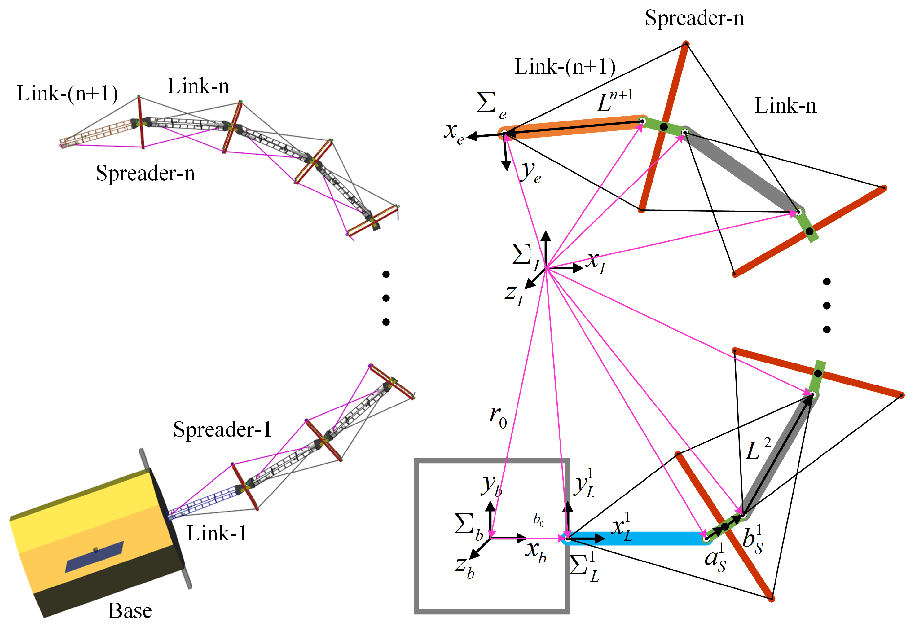
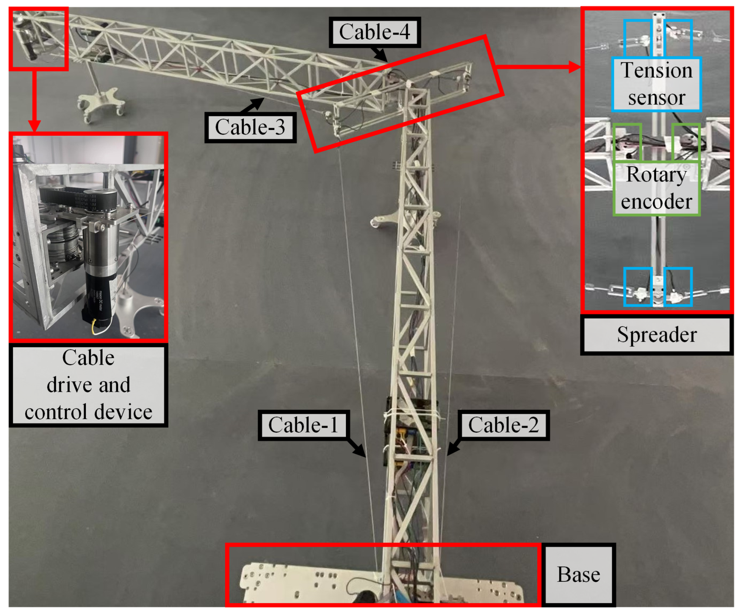
2.1. Description
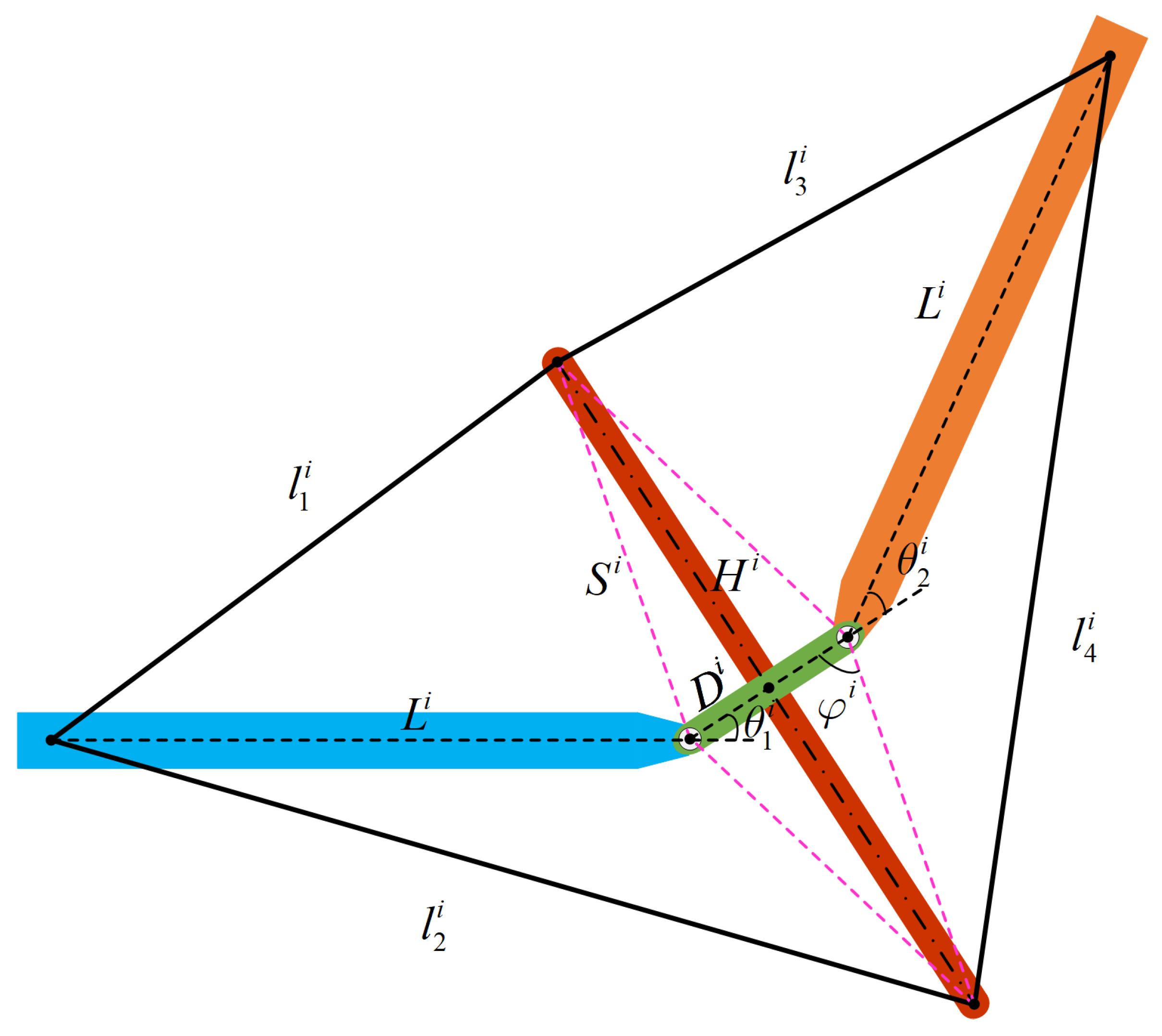
2.2. Joint-to-Cable Kinematics
- Assume that the manipulator only moves in the plane, and the small motion in the z-axis direction is neglected.
- Assume that there is no gravity during the movement of the manipulator.
- Assume that the tendons on both sides of the suspender are fixed in the same horizontal plane, ignoring the position deviation of the tendon’s fixed position.
2.3. Force Mapping
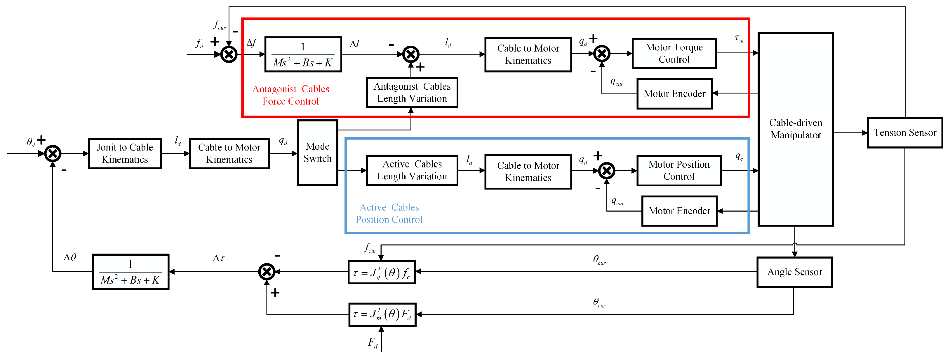
3. Compliance Control
4. Simulation and Experiment
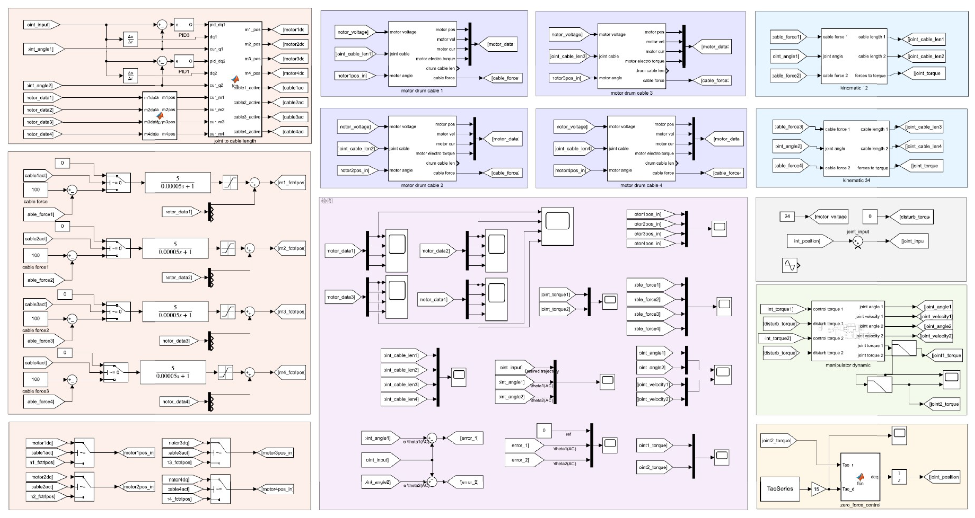
4.1. Simulation Environment
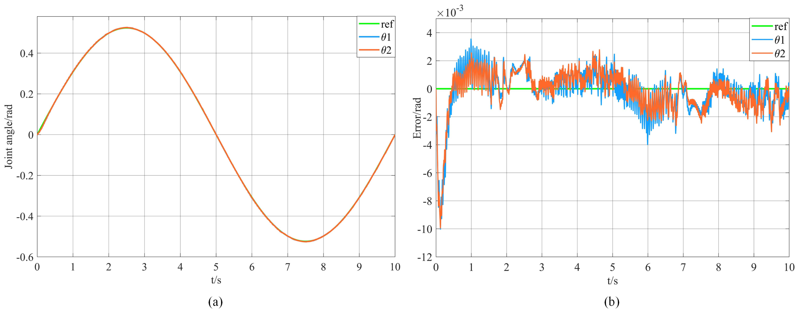
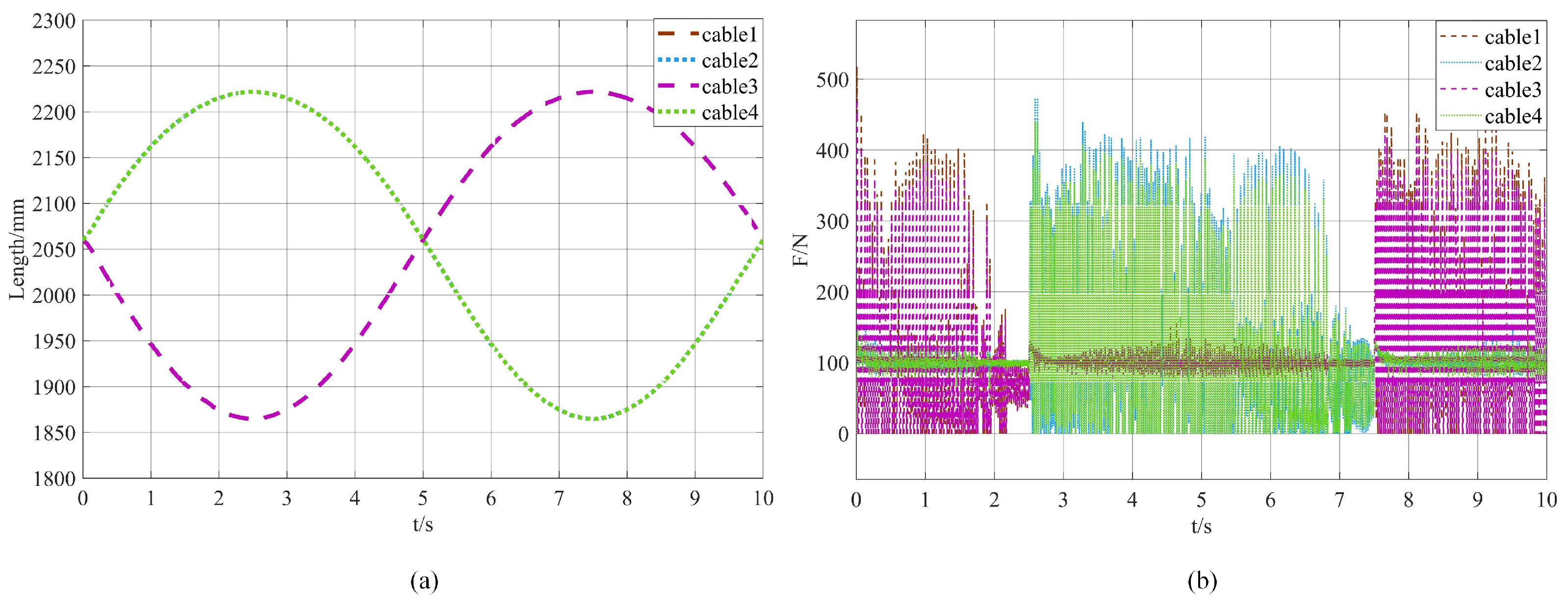
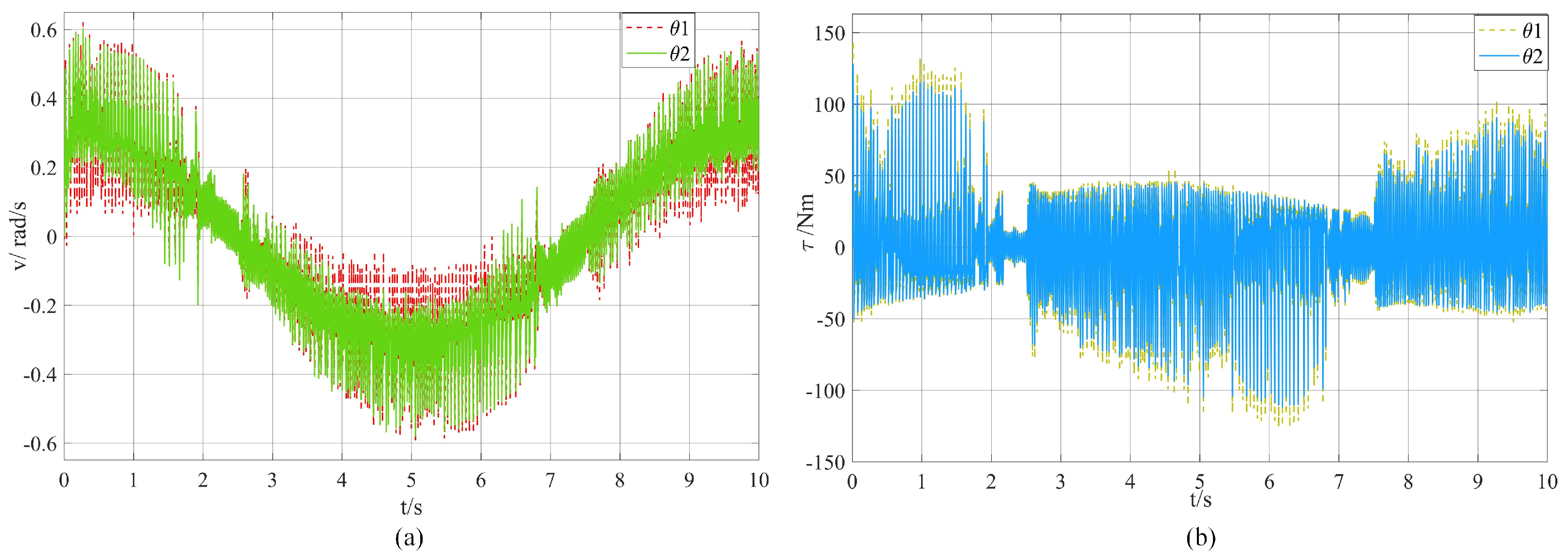
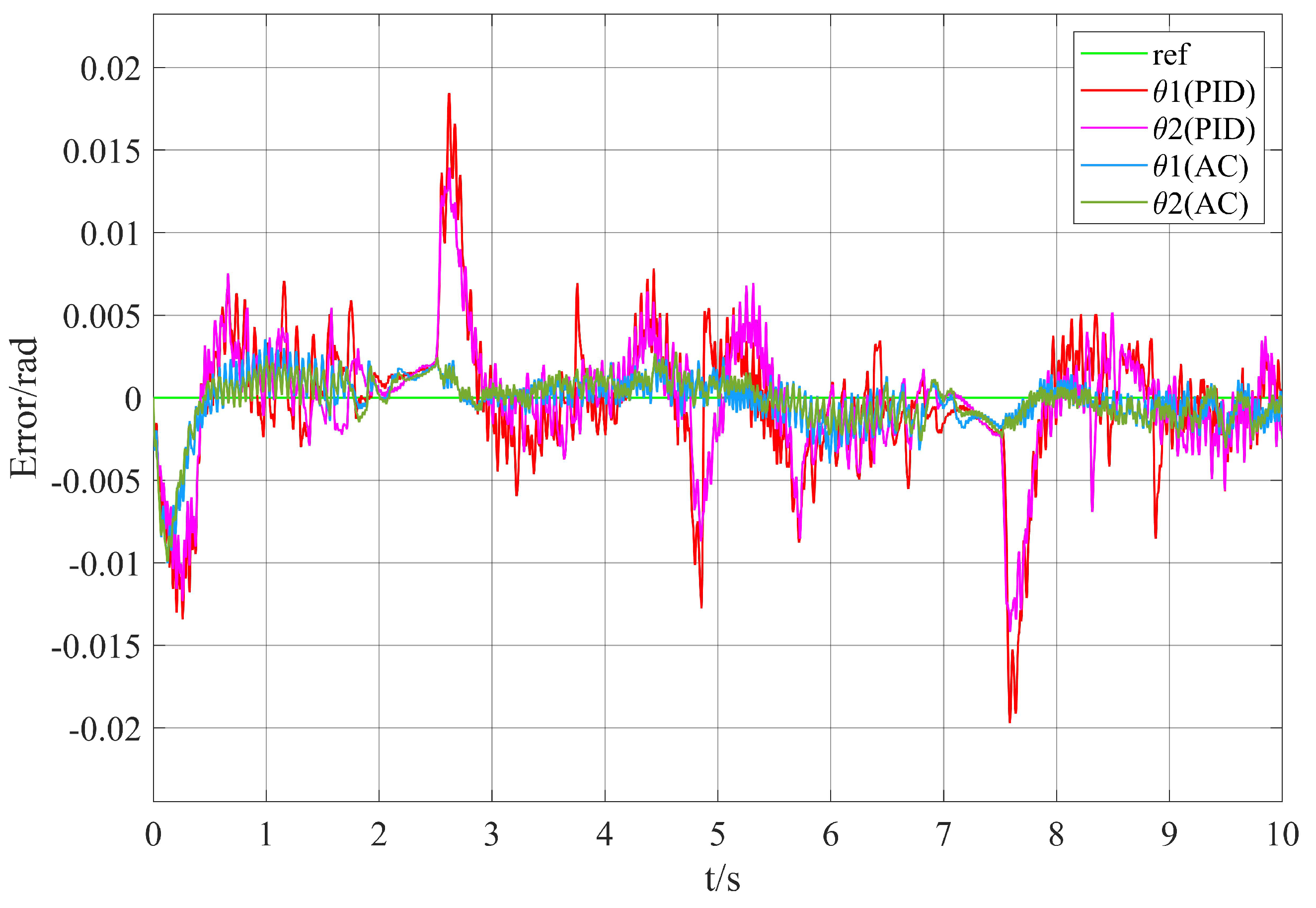
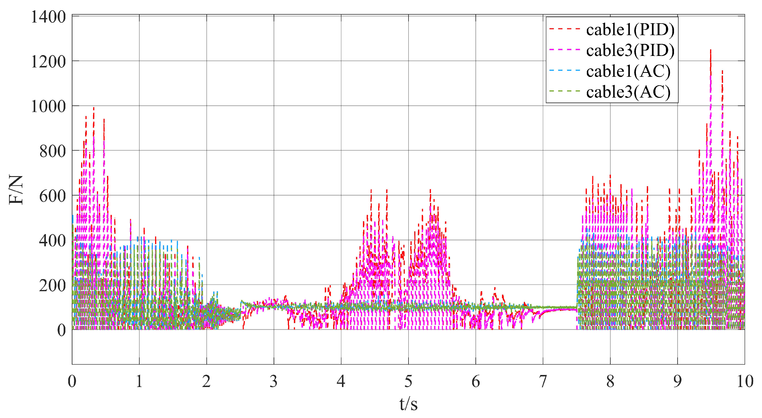
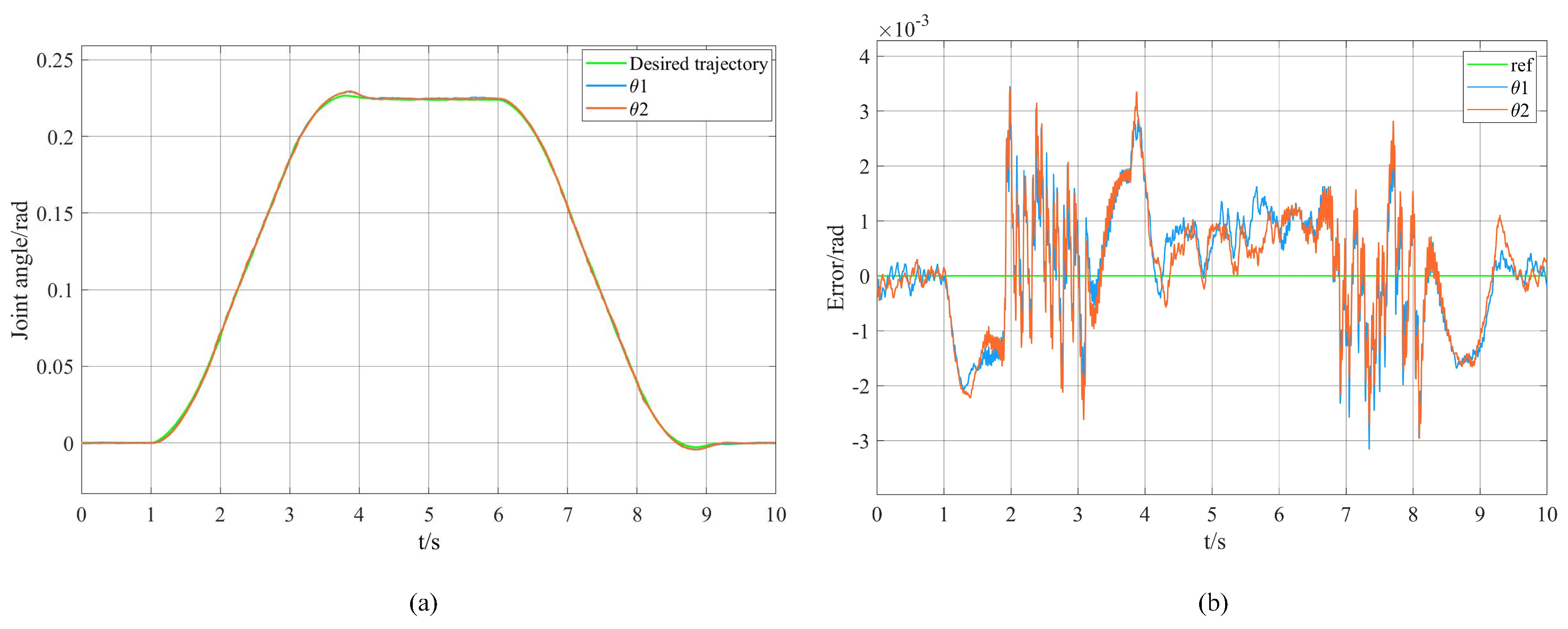
4.2. Trajectory Tracking Simulation
4.3. Zero-Force Drag Simulation
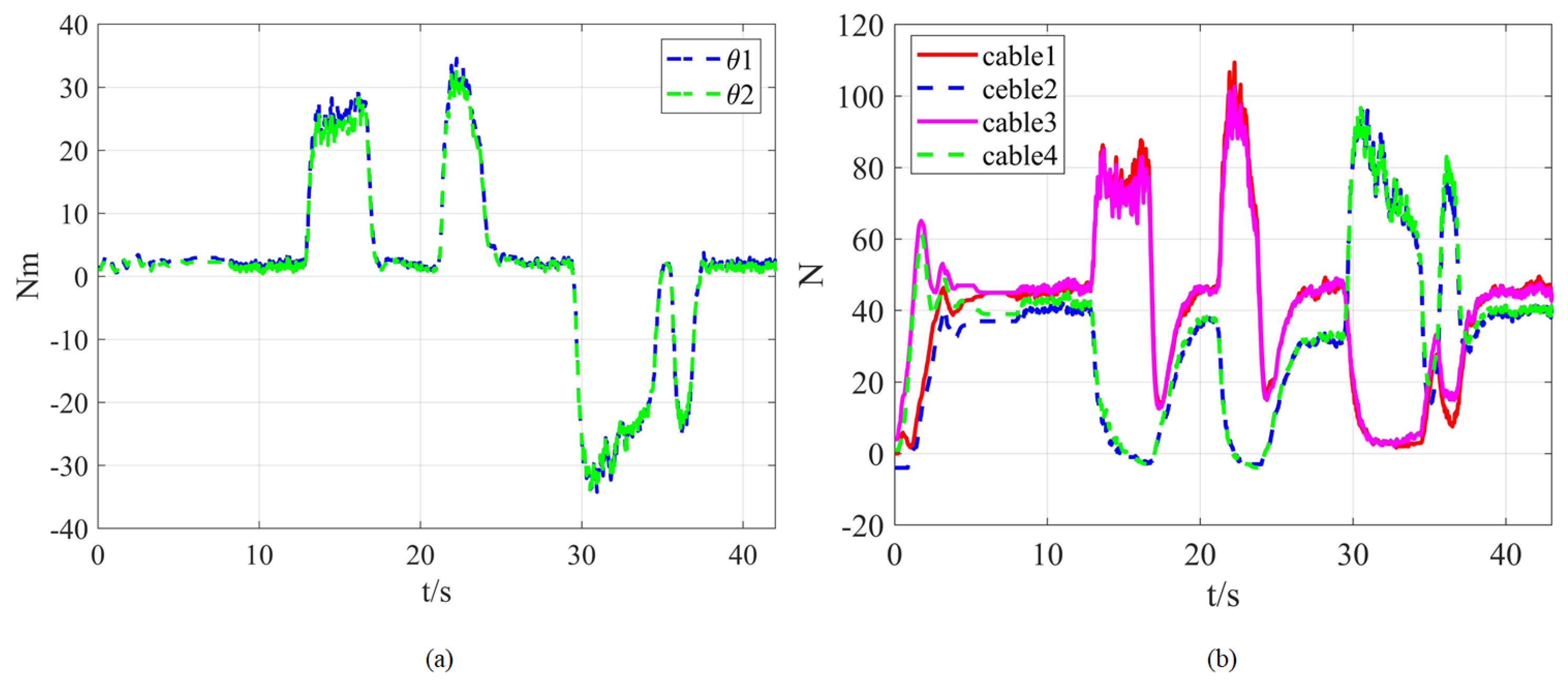
4.4. Experiment
5. Conclusions
Author Contributions
Funding
Data Availability Statement
Conflicts of Interest
References
- Doggett, W.R.; Stohlman, O.R.; Teter, J.; Song, K.; White, B.; Oh, C.J.; Mikulas, M. In-Space Modular Assembly: An Approach for Reliable, Affordable, Precision Space Apertures. In Proceedings of the AIAA SCITECH 2024 Forum, Orlando, FL, USA, 8–12 January 2024. [Google Scholar]
- Wang, L.; Zhu, H.; Xu, W.; Meng, N. Thermal-Structural Analysis of a Large Space Hoop-Column Antenna under Unidirectional Solar Radiations. Thin-Walled Struct. 2024, 198, 111695. [Google Scholar] [CrossRef]
- Nair, M.H.; Rai, M.C.; Poozhiyil, M. The New Era of Walking Manipulators in Space: Feasibility and Operational Assessment of Assembling a 25 m Large Aperture Space Telescope in Orbit. Acta Astronaut. 2024, 225, 1061–1071. [Google Scholar] [CrossRef]
- Garcia-Luis, U.; Gomez-San-Juan, A.M.; Navarro-Medina, F.; Ulloa-Sande, C.; Yñigo-Rivera, A.; Peláez-Santos, A.E. Optimizing Space Telescopes’ Thermal Performance through Uncertainty Analysis: Identification of Critical Parameters and Shaping Test Strategy Development. Aerospace 2024, 11, 231. [Google Scholar] [CrossRef]
- Orlov, V.; Monakhova, U.; Ovchinnikov, M.; Ivanov, D. Fuelless On-Orbit Assembly of a Large Space Truss Structure Using Repulsion of the Service Spacecraft by Robotic Manipulators. Aerospace 2024, 11, 635. [Google Scholar] [CrossRef]
- Friend, R.B. Orbital Express Program Summary and Mission Overview. In Proceedings of the Sensors and Systems for Space Applications II; SPIE: Bellingham, WA, USA, 2008; Volume 6958, pp. 11–21. [Google Scholar]
- Nair, M.H.; Rai, M.C.; Poozhiyil, M.; Eckersley, S.; Kay, S.; Estremera, J. Robotic Technologies for In-Orbit Assembly of a Large Aperture Space Telescope: A Review. Adv. Space Res. 2024, 74, 5118–5141. [Google Scholar] [CrossRef]
- Papadopoulos, E.; Aghili, F.; Ma, O.; Lampariello, R. Robotic Manipulation and Capture in Space: A Survey. Front. Robot. AI 2021, 8, 686723. [Google Scholar] [CrossRef] [PubMed]
- Doetsch, K. Canada’s Role on Space Station. Acta Astronaut. 2005, 57, 661–675. [Google Scholar] [CrossRef]
- Sato, N.; Wakabayashi, Y. JEMRMS Design Features and Topics from Testing. In Proceedings of the 6th International Symposium on Artificial Intelligence, Robotics and Automation in Space (iSAIRAS), Montreal, QC, Canada, 18–22 June 2001. [Google Scholar]
- Boumans, R.; Heemskerk, C. The European Robotic Arm for the International Space Station. Robot. Auton. Syst. 1998, 23, 17–27. [Google Scholar] [CrossRef]
- Crane, C.D., III; Duffy, J.; Carnahan, T. A Kinematic Analysis of the Space Station Remote Manipulator System (SSRMS). J. Robot. Syst. 1991, 8, 637–658. [Google Scholar] [CrossRef]
- Doggett, W.R.; Dorsey, J.T.; Jones, T.C.; King, B. Development of a Tendon-Actuated Lightweight In-Space MANipulator (TALISMAN). In Proceedings of the 42nd Aerospace Mechanism Symposium, Baltimore, MD, USA, 14–16 May 2014. [Google Scholar]
- D’Ambrosio, M.; Capra, L.; Brandonisio, A.; Silvestrini, S.; Lavagna, M. Redundant Space Manipulator Autonomous Guidance for In-Orbit Servicing via Deep Reinforcement Learning. Aerospace 2024, 11, 341. [Google Scholar] [CrossRef]
- Doggett, W.R.; Dorsey, J.; Jones, T.C. Improvements to the Tendon-Actuated Lightweight In-Space MANipulator (TALISMAN) System. In Proceedings of the AIAA SPACE 2015 Conference and Exposition, Pasadena, CA, USA, 31 August–2 September 2015. [Google Scholar]
- Dorsey, J.; Doggett, W.R.; Jones, T.C.; King, B. Application of a Novel Long-Reach Manipulator Concept to Asteroid Redirect Missions. In Proceedings of the 2nd AIAA Spacecraft Structures Conference, Kissimmee, FL, USA, 5–9 January 2015. [Google Scholar]
- Liu, D.; Chen, L. Dual-Arm Space Robot On-Orbit Operation of Auxiliary Docking Prescribed Performance Impedance Control. Aerospace 2024, 11, 867. [Google Scholar] [CrossRef]
- Calanca, A.; Muradore, R.; Fiorini, P. A Review of Algorithms for Compliant Control of Stiff and Fixed-Compliance Robots. Ieee/Asme Trans. Mechatronics 2016, 21, 613–624. [Google Scholar] [CrossRef]
- Hogan, N. Impedance Control: An Approach to Manipulation. In Proceedings of the 1984 American Control Conference, San Diego, CA, USA, 6–8 June 1984; pp. 304–313. [Google Scholar]
- Bajo, A.; Simaan, N. Hybrid Motion/Force Control of Multi-Backbone Continuum Robots. Int. J. Robot. Res. 2016, 35, 422–434. [Google Scholar] [CrossRef]
- Li, J.; Lam, J.; Liu, M.; Wang, Z. Compliant Control and Compensation for A Compact Cable-Driven Robotic Manipulator. IEEE Robot. Autom. Lett. 2020, 5, 5417–5424. [Google Scholar] [CrossRef]
- Su, T.; Niu, L.; He, G.; Liang, X.; Zhao, L.; Zhao, Q. Coordinated Variable Impedance Control for Multi-Segment Cable-Driven Continuum Manipulators. Mech. Mach. Theory 2020, 153, 103969. [Google Scholar] [CrossRef]
- He, G.; Fan, Y.; Su, T.; Zhao, L.; Zhao, Q. Variable Impedance Control of Cable Actuated Continuum Manipulators. Int. J. Control Autom. Syst. 2020, 18, 1839–1852. [Google Scholar] [CrossRef]
- Mazare, M.; Tolu, S.; Taghizadeh, M. Adaptive Variable Impedance Control for a Modular Soft Robot Manipulator in Configuration Space. Meccanica 2022, 57, 1–15. [Google Scholar] [CrossRef]
- Liang, X.; He, G.; Su, T.; Wang, W.; Huang, C.; Zhao, Q.; Hou, Z.-G. Finite-Time Observer-Based Variable Impedance Control of Cable-Driven Continuum Manipulators. IEEE Trans. Hum.-Mach. Syst. 2022, 52, 26–40. [Google Scholar] [CrossRef]
- Zhang, L.; Jia, L.; Yang, P.; Li, Z.; Zhang, Y.; Cheng, X.; Mu, Z. A Convolutional Dynamic-Jerk-Planning Algorithm for Impedance Control of Variable-Stiffness Cable-Driven Manipulators. Micromachines 2022, 13, 2021. [Google Scholar] [CrossRef] [PubMed]
- Li, W.; Huang, X.; Yan, L.; Cheng, H.; Liang, B.; Xu, W. Force Sensing and Compliance Control for a Cable-Driven Redundant Manipulator. IEEE/ASME Trans. Mechatron. 2024, 29, 777–788. [Google Scholar] [CrossRef]
- Li, Z.; Shang, W.; Zhang, B. Hybrid Impedance Control of Cable-Driven Parallel Robots Using Adaptive Friction Compensation. IEEE Trans. Ind. Electron. 2025, 72, 703–713. [Google Scholar] [CrossRef]
- Zhou, B.; Li, S.; Zi, B.; Chen, B.; Zhu, W. Multi-Objective Optimal Design of a Cable-Driven Parallel Robot Based on an Adaptive Adjustment Inertia Weight Particle Swarm Optimization Algorithm. J. Mech. Des. 2023, 145, 083301. [Google Scholar] [CrossRef]
- Sun, H.; Tang, X.; Ge, S.S. Compliant Tracking Control and Force Redistribution for a Portable Cable-Driven Robot. IEEE/ASME Trans. Mechatron. 2024, 1–12. [Google Scholar] [CrossRef]
- Chen, Q.; Li, M.; Wu, H.; Liu, W.; Peng, J. Design, Self-Calibration and Compliance Control of Modular Cable-Driven Snake-like Manipulators. Mech. Mach. Theory 2024, 193, 105562. [Google Scholar] [CrossRef]


| Physicial Structure | Parameters |
|---|---|
| Manipulator Mass | = 5.804 kg |
| Spreader Mass | = 1.368 kg |
| Manipulator Length | L = 1.952 m |
| Spreader Height | h = 0.37 m |
| Motor Reducer Radius | r = 0.03 m |
Disclaimer/Publisher’s Note: The statements, opinions and data contained in all publications are solely those of the individual author(s) and contributor(s) and not of MDPI and/or the editor(s). MDPI and/or the editor(s) disclaim responsibility for any injury to people or property resulting from any ideas, methods, instructions or products referred to in the content. |
© 2025 by the authors. Licensee MDPI, Basel, Switzerland. This article is an open access article distributed under the terms and conditions of the Creative Commons Attribution (CC BY) license (https://creativecommons.org/licenses/by/4.0/).
Share and Cite
Xiang, R.; Xu, H.; Li, X.; Zhu, X.; Meng, D.; Xu, W. Compliance Control of a Cable-Driven Space Manipulator Based on Force–Position Hybrid Drive Mode. Aerospace 2025, 12, 69. https://doi.org/10.3390/aerospace12010069
Xiang R, Xu H, Li X, Zhu X, Meng D, Xu W. Compliance Control of a Cable-Driven Space Manipulator Based on Force–Position Hybrid Drive Mode. Aerospace. 2025; 12(1):69. https://doi.org/10.3390/aerospace12010069
Chicago/Turabian StyleXiang, Runhui, Hejie Xu, Xinliang Li, Xiaojun Zhu, Deshan Meng, and Wenfu Xu. 2025. "Compliance Control of a Cable-Driven Space Manipulator Based on Force–Position Hybrid Drive Mode" Aerospace 12, no. 1: 69. https://doi.org/10.3390/aerospace12010069
APA StyleXiang, R., Xu, H., Li, X., Zhu, X., Meng, D., & Xu, W. (2025). Compliance Control of a Cable-Driven Space Manipulator Based on Force–Position Hybrid Drive Mode. Aerospace, 12(1), 69. https://doi.org/10.3390/aerospace12010069