Abstract
Enhancing thermal efficiency and minimizing weight are prevailing issues in aero engines. Owing to its hollow structure, the twin-web turbine disc exhibits remarkable weight reduction properties, while its enhanced cooling constitutes a novel challenge. In this study, a twin-web turbine disc cavity system is numerically investigated. To enhance the cooling effect and minimize pressure loss, a multi-objective genetic algorithm and Kriging surrogate model are employed to optimize the radial height of the pre-swirl nozzle and receiver hole in the disc cavity system. The results indicate that the overall performance of Opt-3, derived from the Technique for Order Preference by Similarity to the Ideal Solution method within the Pareto frontier, is superior. This configuration achieves a uniform low distribution of rotor temperatures while maintaining moderate pressure losses. Notably, the maximum temperature is reduced by 21.1 K compared to the basic model, with pressure losses remaining largely unchanged. Additionally, an increase in the flow ratio leads to a reduction in both the maximum temperature and average temperature of the back web while simultaneously increasing the temperature of the front web and augmenting pressure losses. However, it is important to note that the degree of variation in these parameters diminishes with increasing flow ratios.
1. Introduction
Enhancing the thermal efficiency of the engine in aero-engine development requires raising the gas temperature at the turbine inlet. Nevertheless, this approach has the potential to greatly diminish the longevity of high-temperature components [1]. Hence, there is an urgent need for enhanced cooling techniques, and the study of twin-web turbine discs (TWDs) offers a promising new avenue [2].
Most contemporary research primarily focuses on the flow and heat transfer characteristics within the single-web turbine (SWD) cavity. Shen et al. [3] investigated the temperature drop in a radial pre-swirl system employing various impeller configurations. Xia et al. [4] introduced a double-row pre-swirl nozzle designed to enhance heat transfer at greater radii. Additionally, further studies have been conducted on the optimization of pre-swirl systems, aiming to reduce the temperature of cooling air while increasing adiabatic efficiency [5,6]. As depicted in Figure 1, the twin-web turbine (TWD) exhibits distinct structural differences from the SWD. Specifically, it features a hollow disc configuration, resulting in an inner cavity between the two webs. This design facilitates coolant flow, thereby enhancing heat transfer, which is beneficial for mitigating local thermal stress in the turbine disc and extending its service life and mechanical strength. However, given the overall similar structural characteristics, in-depth theoretical analyses and optimization methods associated with the SWD disc cavity may be applied to the investigation of the TWD [7]. Zhao [8] previously conducted research on a hollow turbine disc cooling structure, revealing that cooling efficiency improved with the implementation of both center and high intakes. Zhang [9,10] developed a model incorporating curved ribs within the inner cavity to enhance heat transfer. Li [11,12] proposed an innovative TWD design featuring staggered pin fins located in the inner cavity, with the objective of achieving minimal weight and temperature while adhering to stress limitations. Furthermore, Ma [13,14] established a TWD cavity system equipped with a high-radius pre-swirl system. Ma’s study initially implemented the pre-swirl method to enhance heat transfer within the TWD cavity; however, it did not account for the relationship between cooling performance and pressure loss.
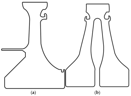
Figure 1.
Schematic diagram of (a) a SWD and (b) a TWD.
Machine learning is frequently employed in complex engineering design to establish the nonlinear correlation between structural parameters and design objectives [15]. It is then integrated with heuristic algorithms to address diverse optimization design challenges [16], including optimizing aero engine performance [17,18] and designing aerospace spacecraft [19]. The surrogate model method has emerged as a viable solution for addressing costly multi-objective problems in aeronautical engineering applications. These models employ adaptive sampling approaches, resulting in a significant reduction in objective evaluation [20,21]. The configuration of the turbine disc cavity system is intricate, and the process of multi-objective optimization typically involves the exploration of a wide range of design possibilities. Various types of surrogate models are accessible, including radial basis functions [22], support vector machines [23], and Kriging models [24]. The Kriging model is widely utilized due to its great accuracy in fitting and predicting nonlinear situations. It is frequently employed in turbine-machinery design [25,26,27].
Multi-objective optimization technology based on a surrogate model has been widely applied to optimization designs with high computational cost, such as turbine blade airfoils [28], axial flow compressor rotors [29], aerodynamic and acoustical airfoils [30], etc. A variety of multi-objective optimization methods are used in these applications, including naturally inspired evolutionary algorithms, gradient-based algorithms, and surrogate-based algorithms. Among them, the NSGA-II algorithm is one of the most widely used multi-objective evolutionary optimization algorithms proposed by Ded et al. [31]. The algorithm shows sufficient robustness. In the NSGA-II algorithm, each target parameter is treated individually, and standard genetic manipulations of mutation and crossover are performed on the design. The selection process is based on two main mechanisms: “non-dominant sort” and “crowding distance sort”. In recent years, it has often been used in spacecraft multi-objective optimization design [32,33]. In turbine research, the NSGA-II algorithm is also widely used. Liu et al. [34] predicted the nonlinear dynamics and optimized the damping performance of the bladed disc system through the surrogate model, and Zhang et al. [35] conducted simulation analysis and experimental research on the Pareto optimal assembly scheme of the multistage rotor. However, the surrogate model and multi-objective optimization technology are rarely applied to the optimal design of the disc cavity of the TWD, which limits the development of the new turbine disc.
In this paper, we employ a Kriging surrogate model alongside a Non-Dominated Sorting Genetic Algorithm (NSGA-II) to optimize the TWD cavity system. The methodology underlying this optimization process is elaborated upon in Section 2. Initially, we assess the primary geometric factors influencing the performance of steam turbines, utilizing the Latin Hypercube Sampling (LHS) technique to systematically sample the significant geometric parameters. A Kriging proxy model is constructed based on Computational Fluid Dynamics (CFD) responses, facilitating a parametric analysis of the pre-swirl system’s impact on the temperature and pressure loss within the TWD cavity system. The Pareto front is generated through the NSGA-II algorithm, and the optimal design parameters along this front are ascertained using the Technique for Order Preference by Similarity to the Ideal Solution (TOPSIS) method. In Section 3, we validate the advantages of the proposed optimal structure in enhancing cooling efficiency and mitigating pressure loss through a comprehensive analysis of flow and heat transfer. Additionally, we investigate the effects of the inlet flow ratio on maximum temperature and pressure loss. Section 4 presents the conclusion of this study, summarizing key findings and implications for future research.
2. Methodology
2.1. CFD Calculation
2.1.1. Calculation Model
This study introduces the design of a TWD cavity system. The model consists of a TWD, two rotor-stator cavities, and an inner cavity. The hub incorporates a total of 60 pre-swirl nozzles, each with a diameter of 5 mm. In addition, coolant outlets, also with a diameter of 5 mm, are uniformly distributed along the periphery of the disc. The front web is fitted with reception holes measuring 8 mm in diameter. Notably, a coolant outlet seam is positioned on the right side of the disc, featuring a fluid width of 3 mm that extends along the edge of the disc. During operation, coolant is initially directed from pre-swirl nozzle 1 into rotor-stator cavity 1 to facilitate cooling of the external wall of the front web. The freezing rotor surface method is used at the transition interface. From there, it flows into the inner cavity through the receiver holes, where it merges with the coolant entering from the inlet-mid and subsequently exits through the outlet-mid. Coolant from nozzle 2 is routed into rotor-stator cavity 2 before being expelled through the outlet seam. Figure 2 illustrates the dimensions of the system, while Table 1 delineates the key parameter values associated with the design.
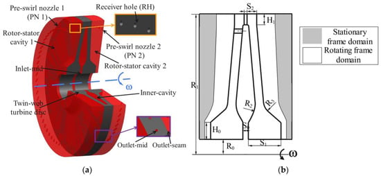
Figure 2.
Three–dimensional geometry (3/4 model) (a) and structural parameters (b) of the TWD.

Table 1.
Parameter values of TWD.
For similar rotating disc cavity models, in order to save computing resources, a partial period domain is generally selected for CFD simulation (CFX 17.2) [36]. In this paper, 60 receiver holes and pre-swirl nozzles on both sides are respectively arranged. Consequently, to optimize computational resources, a periodic domain model representing 1/60 of the TWD cavity system is employed for the subsequent calculations. The calculation domain of the model includes fluid domain 1, fluid domain 2, and solid domain. Rotor-stator cavity 1 and inner cavity are combined into one fluid domain 1, while rotor-stator cavity 2 is considered fluid domain 2. The TWD is regarded as a solid domain consisting of GH4169 superalloy, which has excellent high-temperature resistance at 1200 K. Its thermodynamic parameters can be found in the literature [9].
2.1.2. Boundary Conditions and Grids
To simulate the heat transfer of turbine blades, a uniform heat flux boundary condition of 420,000 W/m2 was applied on the surface adjacent to the disc edge of the high-temperature blades [37]. The interface between the fluid domain and the solid domain was employed as the coupling interface for information transfer, and adiabatic boundary conditions were adopted for the other walls. During the optimization process, the relevant boundary conditions remain unaltered. Among them, the inlet mass flow rate of the inlet-mid and all the nozzle was 0.0083 kg/s, and the total inlet temperature was 700 K. The outlet-mid and outlet-seam were set as an average static pressure outlet of 1 MPa. The rotational speed of TWD was 10,000 rev/min. Coolant was an ideal gas with a specific heat value of 4182 (J/kg∙K), thermal conductivity value of 0.6 (W/m∙K), and dynamic viscosity calculated using Sutherland’s law.
In the fluid domain adjacent to the solid structures, the presence of the boundary layer results in elevated temperature and velocity gradients. Consequently, the grid resolution is increased at the fluid–solid interface, as well as at the coolant inlets, outlets, and reception holes. Following this approach, the boundary layer within 15 units of the walls of these three fluid domains was refined to a first-layer mesh with a thickness of 0.05 mm, with a growth rate set at 1.1. The grid configuration is illustrated in Figure 3a.
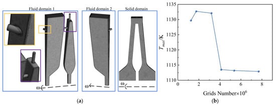
Figure 3.
(a) Grid diagram and (b) grid independence verification.
Due to the rise in centrifugal temperature and the uniform heat flux applied to the edge of the disc by the simulated blade, the maximum temperature of the TWD invariably occurs at the edge of the disc. This constitutes the most conspicuous indicator for assessing cooling efficiency. Hence, the maximum temperature of the TWD is employed to verify the grid independence. Figure 3b illustrates how the value of decreases to less than 1 K when the number of grids surpasses 6,108,524. The grid number is chosen for further calculation in order to strike a compromise between calculation speed and accuracy.
2.1.3. Numerical Methods
In the optimization design work of this paper, fluid flow and heat transfer are the primary focuses, and steady-state analysis is adequate to capture the principal characteristics of the system [38]. Consequently, the fluid motion and heat transfer within the rotating cavity are delineated by the steady-state three-dimensional Reynolds mean Navier-Stokes (RANS) equation.
Xu’s rotating disc experiment [39] is used to verify the accuracy of the turbulence model. In Xu’s experiment, the edge of the disc was heated with a resistance wire with a heating power of 1100 W to simulate the heat transferred by the blade. The coolant with a mass flow rate of 200 kg/h from the air collecting chamber through 30 evenly arranged pre-swirl holes impacts the rotating disc, convective heat transfer with the disc surface, and then outflow from the disc edge. According to the geometric and boundary conditions in reference, a simulation model was established to verify the turbulence model using the same near-wall mesh treatment as in this paper. In order to save computing resources, a period domain is selected for simulation. A period domain includes a pre-swirl hole.
In order to eliminate the influence of the coolant temperature of the inlet on the temperature distribution of the disc surface, the temperature of each point on the windward side minus the inlet temperature is taken as the excess temperature of the windward side . Figure 4 shows the calculation model and the comparison between the calculated results and the experimental data. The results show that the test data of the turbulence model are more consistent with the trend of the experimental data. Among them, the test data of is in better agreement with the experimental data of high radius position. Therefore, in this paper, the turbulence model is chosen for subsequent calculations.
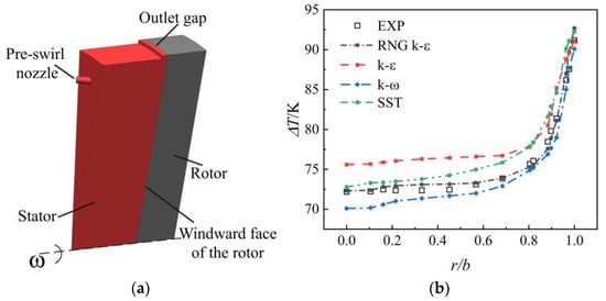
Figure 4.
(a) Simulation model and (b) turbulence model validation results.
2.2. Optimization Calculation
In this study, a Kriging surrogate model in conjunction with a multi-objective genetic algorithm is employed to optimize the design of a twin-web turbine (TWD) cavity system. Figure 5 illustrates the flow diagram of the optimization process. The optimization problem is defined by identifying the design variables and optimization objectives. Subsequently, the hyper-cube approach is utilized to calculate the number of training samples that fall within a specified range of variables. CFD simulations are conducted for each scenario outlined in the training sample. The results from the CFD numerical calculations are utilized to generate a training sample comprising the values of the design variables and optimization objectives. This training sample is then employed to train the selected surrogate model. Test samples are generated randomly, and the optimization objective for the test samples is determined using both the trained surrogate model and CFD computations. If the error meets the specified criteria, the multi-objective genetic algorithm is applied to identify the optimal design point. Conversely, if the error does not satisfy the requirements, an increase in the sample size is necessitated.
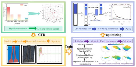
Figure 5.
Optimization process.
2.2.1. Identification of Significant Variables
Numerous factors affect the temperature and pressure of a TWD cavity system, but it requires a lot of computing power to optimize these parameters jointly. As a result, an analysis of the distinctive significance of crucial factors in the TWD cavity system is required. Kong [40,41] highlighted that the flow status and temperature distribution of coolant in a turbine disc cavity system are directly influenced by pre-swirl nozzle and receiver holes.
To quantitatively identify the critical parameters influencing the flow heat transfer performance, the random forest algorithm (RF) was employed to analyze the effects of key structural parameters on the cooling performance of the system, such as the height and angle of the pre-swirl nozzles and receiver holes in the TWD cavity system. Using an independent decision tree as the fundamental building block, RF chooses specific samples at random from the data set and produces a result for each tree based on the properties of the object. The relevance of the structural characteristics affecting the target variable is determined by calculating the depth of the split point, which is where the variable is located. This method is commonly used to explore the significance of attributes in order to achieve the goal of dimensionality reduction [42].
In this paper, the interpretable variables selected include the radial height of the pre-swirl nozzle and the receiving hole (RPN1, RPN2, RRH), the angle of the pre-swirl nozzle and the receiving hole (APN1, APN2, ARH). The parameters and ranges of parameter feature importance are shown in Table 2. The orthogonal experimental table was established with six variables, and 40 groups of samples were acquired. The tmax under the corresponding structure was computed by CFD and was utilized as the dataset of the random forest algorithm.

Table 2.
Parameters and ranges of feature importance are studied.
Figure 6 demonstrates the random forest diagram and the result of feature importance on . As Figure 6b shows, the radial position of the nozzle and receiver hole has a greater impact on the heat transfer performance in the TWD cavity system than the angle. The parameters for the radial height of the pair of nozzles were found to have significance values of 0.47 and 0.22, respectively. The heat transfer performance of individual components is greatly affected by the varying radial height of the nozzles, with the influence size being PN1 > PN2 > RH. The interaction between PN1 and RH has a significant impact on the flow condition of the coolant in the rotor-stator cavity 1 and the inner cavity. The matching relationship between PN1 and RH plays a crucial role in this effect. However, the impact of PN2 heat transfer properties is subject to specific restrictions.
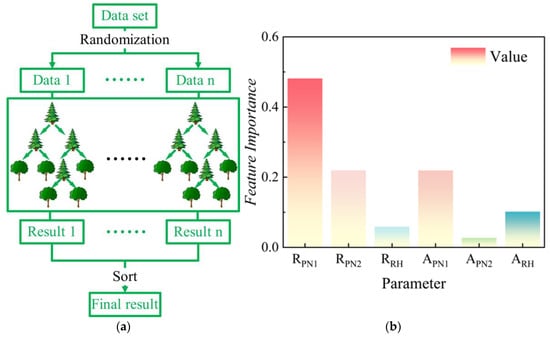
Figure 6.
(a) Random forest diagram and (b) result of feature importance.
Typically, the flow and heat transfer properties of the TWD cavities are highly responsive to changes in the radial height of each component. Thus, this article optimizes the radial position of the nozzle and receiver hole.
2.2.2. Optimization Objective
In turbine design, an increase in cooling performance is usually accompanied by a loss of aerodynamic performance. In this paper, the coolant in rotor-stator cavity 1 is mixed with the coolant in the inner cavity through the receiver holes. The mixing process inevitably results in pressure loss and local entropy increase. The maximum temperature of the turbine disc is the most intuitive influence on the cooling performance.
Therefore, two optimization objectives are defined as the maximum temperature and dimensionless pressure loss .
where, is the outlet pressure of the outlet-mid, and and are the average pressure and average velocity of the two entrances in the fluid domain 1, respectively, which are calculated by Formulas (2) and (3).
The optimization targets should be in the same order of magnitude, and the output of genetic algorithm optimization is the global minimum. Therefore, it is necessary to transform the optimization objectives to ensure that the three optimization objectives are in the same order of magnitude level. Normalization involves mapping data to a uniform range between 0 and 1. Normalizing the training data ensures that all variables contribute equally to the learning process, preventing any single variable from overwhelming the training.
where, represents the current sample value, and represent the minimum and maximum values in the sample, respectively.
2.2.3. Optimal Scheme Design
Optimal scheme design plays a crucial role in the optimization strategy that relies on surrogate models. LHS is a widely used and user-friendly experimental design technique that offers effective global parameter search. The approach was initially suggested by McKay et al. [43]. The design matrix of the LHS comprises a column for each factor, with the column determined by the random selection of N levels. Due to its random generation, the matrix exhibits excellent space-filling characteristics. Furthermore, this sampling technique does not require additional diversity in order to achieve more dimensions, and this independence is a significant advantage of the sampling scheme [44]. This study utilized a total of 40 sampling locations to examine pre-swirl nozzles 1 and 2, as well as receiver holes (RPN1, RPN2, RRH), at various radial heights. Table 3 displays the range of input variables. Figure 7 displays the locations where representative samples were taken. Forty groups of data were used for training samples in a cube design, and eight groups of data were randomly picked as test samples.

Table 3.
Range of the input variable.
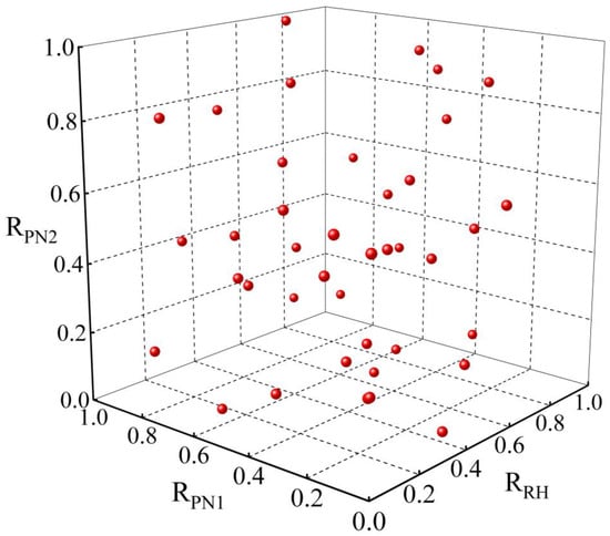
Figure 7.
Latin Hypercube Sampling Points.
2.2.4. Surrogate Model
This research utilizes an LHS experimental design to acquire samples, which are then subjected to CFD calculations as a response. The provided data samples are utilized to train the Kriging surrogate model. In the context of a multidimensional optimization problem, the Kriging surrogate model is capable of estimating the value of unknown points by utilizing the known data points. This work utilizes the conventional spatial correlation function to assign initial values of 0.5 for the length scale θ and 1 for the smoothness degree parameter p. The L-BFGS-B optimization algorithm is employed to determine the hyperparameters of the model and efficiently optimize the relevant hyperparameters, thereby enhancing the model’s ability to accurately fit the data and improving prediction accuracy.
Three radial height parameters are used as input factors, while dimensionless loss and normalized maximum temperature are used as output variables in the Kriging surrogate model presented in this paper, as indicated by Formulas (5) and (6). The division of the training set and test set among the 40 samples obtained via the LHS experimental design is not predetermined. The test set is comprised of eight randomly chosen samples. The details and confirmation are displayed in Table 4 and Figure 8.
where, and are dimensionless parameters after normalization, respectively.

Table 4.
Comparison of the predicted value with the actual value of the test set.
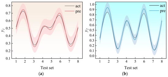
Figure 8.
Test set validation of output parameters: (a) y1 and (b) y2.
In Figure 8, the post-script act corresponds to the value computed by CFD, whereas the pre-script reflects the value forecasted by the Kriging model. The margin of error is 10%, and all test data fall within the acceptable range of error. The results demonstrate the exceptional effectiveness of the Kriging model in accurately capturing the correlation between input and output variables, resulting in dependable and resilient predictions, as evidenced by the R2 value of 96%.
2.2.5. Multi-Objective Genetic Algorithm
In this paper, two objective functions are defined.
The specific operating conditions for the termination of the optimization algorithm in this paper are described as follows:
- (1)
- The congestion distance calculated in NSGA-II exceeds the threshold;
- (2)
- Individuals are at the Pareto frontier;
- (3)
- In each generation of the updated model, the number of individuals added is less than 10% of the first non-dominant frontier population.
In the optimization process, the crossover probability is 0.8, the mutation probability is 0.1, the initial population size is 2000, the termination condition of iteration generation is 500, and finally, 29 new samples are obtained.
Determining the optimal design solution through multi-objective optimization design point decision is a difficult procedure that requires making trade-offs between several competing objectives. Prior to making a decision in multi-objective optimization, the dimensions and scales of the target space should be unified because different targets may have different dimensions. TOPSIS is employed in this paper’s decision-making procedure. This technique for reducing Euclidean dimensionality is frequently applied in multi-objective optimization decision-making processes [45,46]. The literature [47] contains the fundamental ideas.
3. Results
3.1. Optimization Results
Figure 9 displays both the fitness values achieved during the optimization process and the final Pareto solution. A Pareto solution is a group of optimal solutions in a multi-objective problem, where each target is optimized to its fullest extent, but further optimization of one objective would require compromising the optimization of other objectives. The solutions are mutually non-dominant, meaning that no single option is superior to the other in achieving all goals. This is determined by evaluating the dominant relationship between the alternatives.
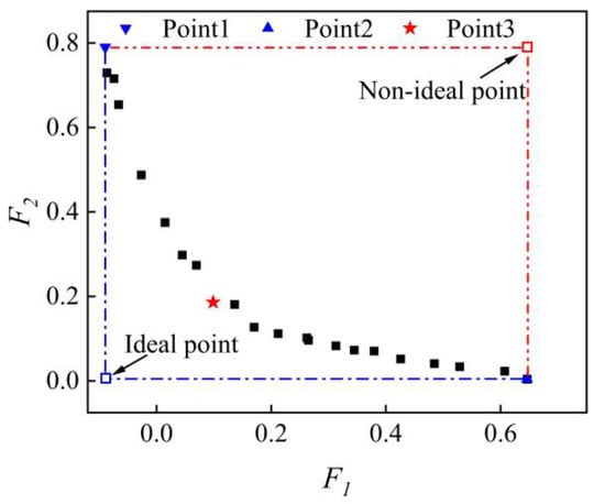
Figure 9.
Pareto front with NSGA-II.
Points 1 and 2 in Figure 9 represent extreme Pareto solutions. This provides us with hypothetical ideal point and non-ideal point. Based on these two points, point 3 is the ultimate optimal design point that the TOPSIS approach yields. The achievement of equilibrium between cooling effectiveness and pressure loss at this juncture validates the feasibility of multi-objective optimization methodologies. However, this essay simply highlights the greatest aspects of the framework; other design considerations still hold true for other requirements.
Table 5 displays the optimized outcomes of the structural parameters. Table 6 presents the outcomes of the Kriging surrogate model and CFD computation, along with the discrepancies between them. The relationship between the cooling impact and the relative pressure loss is clearly positive. Opt1–3 is the outcome of a multi-objective optimization process. The surrogate model used to estimate the pressure loss coefficient has an error rate of approximately 3%, while the error rate for estimating the cooling impact is around 4%. Furthermore, Opt-3 can also attain superior overall performance compared to the other two endpoints. When the primary factor to consider is the heat transfer coefficient, the Opt-1 structure can attain the lowest local high temperature. However, the pressure loss associated with the Opt-1 structure is more than four times greater than that of the Opt-3 structure. Similarly, the Opt-2 structure has the lowest relative pressure loss, although it has the least effective cooling capability. This work presents the relative optimal findings of the design variables in the pre-swirl system of a TWD cavity. The results are based on a Kriging surrogate model that is driven by a large number of CFD computations. This research provided a common comparison of the Bas model in order to verify the superiority of the optimization model.

Table 5.
Optimized design variables and optimization results of structural parameters.

Table 6.
Kriging surrogate model and CFD calculation results and errors.
Figure 10a shows the average and maximum TWD surface temperatures for the four scenarios. The mean temperature of the TWD surface is intricately linked to the heat transfer coefficient. The Opt-1 structure has the lowest temperature, while the Opt-2 structure has the highest temperature. The temperatures of the remaining three structures are similar. The location of failure resulting from thermal issues consistently occurs in close proximity to the area with the greatest temperature. Therefore, the maximum temperature of the rotor surface serves as another crucial measure for assessing the effectiveness of the cooling system. Both the maximum temperature and the average temperature exhibit similar patterns of variation. In the optimized model, it can be concluded that the front web temperature of TWD is lower than the back web temperature. The Opt-3 structure achieves the most efficient cooling effect by maintaining the lowest maximum temperature and a reasonably low average temperature. It is important to mention that the disparity between the average and highest temperatures of the Bas structure is minimal, suggesting that the temperature distribution on the surface of the Bas structure is relatively even.
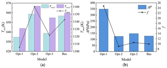
Figure 10.
Comparison of (a) rotor surface temperature and (b) pressure difference of inlet and outlet.
In Figure 10b, the dimensionless pressure loss and pressure differential at the inlet and exit of the TWD cavity system with various ideal designs are compared. The Opt-1 structure exhibits a significantly greater pressure difference compared to the other structures. Similarly, when comparing the Opt-2, Opt-3, and Bas structures, the pressure difference increases for the receiver hole located at a lower radial location. The radial position of the receiver hole is a significant factor in determining the pressure loss of the TWD disc cavity system. At a low radius, the presence of a receiver hole might cause significant pressure loss as a result of coolant mixing. However, as the radial position increases to a particular height, the stress level rises, and the reliability decreases.
The Opt-3 configuration obtained from the Pareto optimal solution using the TOP-SIS method demonstrates excellent overall performance, effectively improving the cooling effect while keeping pressure loss low. When compared to Opt-1, the maximum temperature increased by 16.1 K, and the pressure loss decreased by 201.2 kPa. In comparison to Opt-2 and the base model, the maximum temperature of the TWD decreased by 38.7 K and 21.1 K, respectively, while the pressure loss stayed relatively constant.
3.2. Flow and Heat Transfer
Figure 11 displays the temperature distribution and flow patterns within the TWD cavity system. The results indicate that the presence of a high-radius pre-swirl nozzle has a significant impact on the cooling effect in a system with a receiver hole. However, within the rotor-stator cavity 2, where there is an absence of a receiver hole, the lower nozzle generates a more expansive cryogenic area. It is important to mention that receiver holes with varying heights will have a considerable impact on the flow condition of the coolant in the cavity. This, in turn, will affect the overall cooling effectiveness and the pressure loss resulting from mixing.
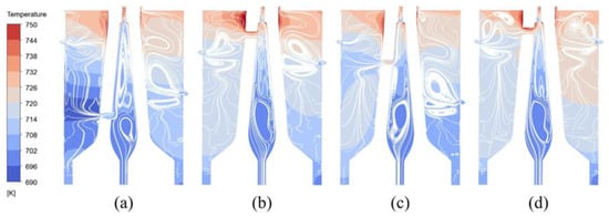
Figure 11.
Temperature contours and streamlines of (a) Opt-1, (b) Opt-2, (c) Opt-3, and (d) Bas.
The flow state within the inner cavity has similarities to the “source-sink” flow. However, the receiver hole has an impact on the establishment and development of the four regions. When the receiver hole is located at a small radius, as depicted in Figure 11a, the coolant within the rotor-stator cavity 1 enters the inner cavity through the receiver hole. This impedes the complete expansion of the source region and is constrained by the coolant in the inner chamber, causing it to flow along the radial direction. Currently, the coolant temperature is low, resulting in improved cooling efficiency for Opt-1. However, this also leads to higher pressure loss. In contrast, Figure 11b,d demonstrate that the jet flow at the receiver hole significantly impacts the formation of the sink region. This is also the primary reason for the minimal pressure loss resulting from the temperature difference and mixing between the front and back webs of Opt-2 and Bas. The structure Opt-3 involved the use of a jet at the receiver hole to disrupt the Ekman layer close to the front web, resulting in an intensified heat transfer effect due to increased turbulence. However, the impact on the Ekman layer close to the back web was minimal. The structure Opt-3 exhibits a significant disparity in temperature between the front and back webs due to this reason.
Figure 12 displays the convective heat transfer coefficients at the walls of TWD rotor-stator cavity 1 (a), inner cavity (b), and rotor-stator cavity 2 (c). The rotor-stator cavity 1 exhibits a pattern of initially growing and then decreasing, with the largest convective heat transfer coefficient observed near the entrance of the receiver hole. Furthermore, the jet expelled from the nozzle will induce oscillations in the curve within a certain range. The convective heat transfer coefficient of Opt-1 is significantly greater than that of other models. The four models exhibited analogous patterns within the internal cavity. The convective heat transfer coefficient experiences a dramatic change, particularly near the exit of the receiver hole, as a result of the standing vortex formed below and behind the direction of rotation. As the radius of this mutation increases, the cooling of the high-temperature zone becomes increasingly disadvantageous. Nevertheless, as a result of the nozzle jet’s impact on the rotor wall, the flow direction is altered, leading to the formation of a disturbance vortex in the opposite direction at the outer edge. This, in turn, causes a significant increase in the convective heat transfer coefficient, resulting in a “peaking” mutation. To summarize, both Opt-1 and Opt-3 demonstrate elevated convective heat transfer coefficients in the three spinning cavities, leading to increased cooling mass.

Figure 12.
Convective heat transfer coefficient of (a) rotor-stator cavity 1, (b) inner cavity, (c) rotor-stator cavity 1.
Figure 13 displays the Nusselt number for the front web outer wall, front web inner wall, back web inner wall, and back web outer wall of the TWD. It is important to mention that, unlike the variation in convective heat transfer coefficient, all four models exhibit similar alterations in the Nusselt number at the entry of the receiver hole as a result of the coolant converging. Due to the greater coolant temperature at the high radius and its flow against the direction of the radius, the Nusselt number initially reduces and subsequently grows. Conversely, the coolant flow along the radius of the low radius raises the Nusselt number along the radius. Specifically, when the receiver hole is positioned at a larger radius, the heat transfer efficiency in the high-temperature region will be diminished. This is also a significant factor contributing to the elevated maximum temperature of Opt-2. However, near the exit of the receiver hole, there is an area with a low local Nusselt number that is located below and behind the direction of rotation. This is caused by the viscous dissipation of the corner resulting from the disorderly reflux. Furthermore, as the jet exiting the receiver hole does not collide with the back web wall, it does not significantly affect the Nusselt number of the back web wall. Furthermore, the impact of PN2 on the Nusselt number was restricted.
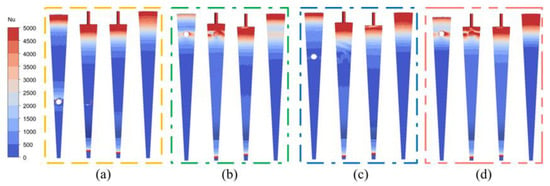
Figure 13.
Wall Nusselt number of (a) Opt-1, (b) Opt-2, (c) Opt-3, and (d) Bas.
3.3. Influence of Flow Ratio
In order to further understand the cooling effect and pressure loss caused by the mixing of coolant in the inner cavity, the influence of nozzle 1 and inlet-mid flow ratio on the four models is also studied. Under the condition of different flow ratios, the total flow rate, rotating speed, heat flow, and other operating conditions of the system remain unchanged, and only the flow rate of the nozzle and the inlet-mid is changed. The specific settings are shown in Table 7, where indicates the mass flow at PN1 and indicates the mass flow at inlet-mid, .

Table 7.
Flow ratio design.
The maximum and average temperature changes in the rotor under different flow ratios are shown in Figure 14. In the legend in Figure 14b, the superscript represents different structures, with the subscript ave1 representing the front web and ave2 representing the back web. With the increase in flow ratio, each parameter shows a monotonically changing trend. It is worth noting that when the flow ratio changes from zero, there is a mutation. This is due to the dramatic change in the flow state in the rotating cavity as the inlet flow begins to be generated at the nozzle. In addition, for the maximum temperature of the rotor, the change of the nozzle still has a more severe impact. With the increase of the flow ratio, the maximum temperature decreases, but the downward trend gradually decreases. Opt-1 is the most drastic change, and the change of Opt-2 is not obvious, which is the same as our optimization goal.
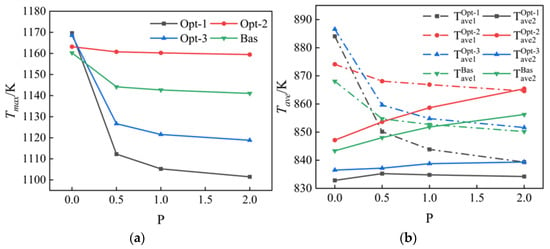
Figure 14.
(a) Maximum temperature and (b) average temperature at different mass flow ratios.
Interestingly, as shown in Figure 14b, the mean temperature changes of the front and back web showed different trends. Due to the great changes in the flow state in the inner cavity, especially the formation of four zones of flow destroyed by the jet at the receiver hole, higher heat transfer efficiency at the front web resulted in a temperature drop. The impact of the jet in the back web is small, but the temperature of the coolant increases, resulting in an increase in the average temperature of the back web.
Figure 15 shows the pressure loss and dimensionless loss at different flow ratios. With the increase in flow ratio, the jet momentum at the receiver hole increases, resulting in a gradual increase in pressure loss, especially in Opt-1. This is what happens when heat transfer is extremely enhanced. Again, increasing cooling efficiency in this system results in higher pressure losses. In the dimensionless variation, the calculated dimensionless loss is larger because the inlet velocity at the nozzle is small. In general, the change in pressure loss is the exact opposite of the change in temperature. Opt-1 and Opt-2 are the most extreme structures, respectively.
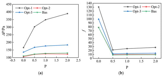
Figure 15.
(a) Pressure loss and (b) dimensionless loss at different flow ratios.
4. Conclusions
To enhance the flow heat transfer performance of the twin-web turbine disc, this study focuses on the radial positions of nozzle 1, the receiver hole, and nozzle 2 as the primary variables. The impact of the pre-swirl system on flow dynamics and heat transfer within the TWD disc cavity was investigated through numerical simulations. Utilizing a database generated from CFD, a hybrid approach combining Kriging and the NSGA was developed to identify Pareto frontiers aimed at maximizing cooling effect while minimizing pressure losses. Subsequently, the TOPSIS decision-making method was employed to recommend an optimal design configuration. The key conclusions are summarized as follows:
- (1)
- An optimization approach integrating Kriging and NSGA is developed and implemented in the optimization procedure to acquire a Pareto frontier with a prediction error of less than 5%. The optimal design configuration can be derived from the Pareto frontier in accordance with the requirements;
- (2)
- The Opt-3 structure acquired through the Pareto optimal solution derived by the TOPSIS method exhibits superior comprehensive performance and is capable of enhancing the cooling effect while maintaining low-pressure loss. Compared with Opt-1, the maximum temperature rose by 16.1 K, and the pressure loss dropped by 201.2 kPa. In contrast, compared with Opt-2 and the base model, the maximum temperature of TWD decreased by 38.7 K and 21.1 K, respectively, while the pressure loss remained largely unchanged;
- (3)
- The radial positioning of the nozzle and the receiving hole plays a crucial role in influencing both flow dynamics and heat transfer characteristics. In the optimal configuration proposed in this study, a significant enhancement in the convective heat transfer coefficient within the stator cavity of the two rotors is observed. The jet emerging from the outlet of the receiving hole disrupts the formation of the Ekman layer within the inner cavity, thereby augmenting the Nusselt number in this region and concurrently reducing pressure losses;
- (4)
- As the flow ratio increases, all four structural configurations demonstrate analogous characteristics. The trend of change exhibits a consistent decline, with the maximum temperature of the TWD gradually decreasing and pressure losses progressively increasing. Furthermore, the average temperature of the front web rises, while the average temperature of the back web experiences a gradual decline attributable to the alterations in flow conditions.
Author Contributions
Conceptualization, Y.G.; Methodology, Y.G.; Software, Y.G. and W.S.; Validation, W.S.; Investigation, Y.G.; Writing—original draft, Y.G.; Writing—review and editing, S.W. and W.S.; Visualization, Y.G.; Project administration, S.W.; Funding acquisition, S.W. All authors have read and agreed to the published version of the manuscript.
Funding
The authors gratefully acknowledge the financial support for this project from the National Science and Technology Major Project of China (No. Y2022-III-0003-0012 and No. J2019-Ⅲ-0023-0067).
Data Availability Statement
Data available on request from the authors.
Conflicts of Interest
The authors declare no conflicts of interest.
References
- Kim, Y.I.; Song, S.J. Unsteady measurement of core penetration flow caused by rotating geometric non-axisymmetry in a turbine rotor-stator disc cavity. Exp. Therm. Fluid Sci. 2019, 107, 118–129. [Google Scholar]
- Zhang, M.; Yao, Q.; Sun, S.; Li, L.; Hou, X. An efficient strategy for reliability-based multidisciplinary design optimization of twin-web disk with non-probabilistic model. Appl. Math. Model. 2020, 82, 546–572. [Google Scholar]
- Shen, W.; Wang, S.; Liang, X. Effect of Impellers on the Cooling Performance of a Radial Pre-Swirl System in Gas Turbine Engines. Aerospace 2024, 11, 187. [Google Scholar] [CrossRef]
- Xia, Z.L.; Wang, S.F.; Zhang, J.C. A Novel Design of Cooling Air Supply System with Dual Row Pre-Swirl Nozzles. J. Appl. Fluid Mech. 2020, 13, 1299–1309. [Google Scholar]
- Lee, J.; Lee, H.; Park, H.; Cho, G.; Kim, D.; Cho, J. Design optimization of a vane type pre-swirl nozzle. Eng. Appl. Comput. Fluid Mech. 2021, 15, 164–179. [Google Scholar]
- Shen, W.; Wang, S.; Wang, M.; Dong, W.; Zhang, K. Transient response and volume model of steam cooling in a rotor–stator disk cavity of gas turbines. Therm. Sci. Eng. Prog. 2024, 53, 102701. [Google Scholar]
- Zhang, M.; Gou, W.; Yao, Q.; Li, L.; Yue, Z. Investigation on heat transfer characteristic and optimization of the cooling air inlet for the twin-web turbine disk. J. Phys. Conf. Ser. 2017, 885, 012011. [Google Scholar]
- Zhao, X.; Xu, G.; Luo, X.; Deng, H. Cooling structure on double-web turbine disk with equal mass scheme. J. Beijing Univ. Aeronaut. Astronaut. 2019, 35, 527–531. [Google Scholar]
- Zhang, M.; Gou, W.; Li, L.; Wang, X.; Yue, Z. Multidisciplinary design and optimization of the twin-web turbine disk. Struct. Multidiscip. Optim. 2016, 53, 1129–1141. [Google Scholar]
- Zhang, M.; Gou, W.; Li, L.; Yang, F.; Yue, Z. Multidisciplinary design and multi-objective optimization on guide fins of twin-web disk using Kriging surrogate model. Struct. Multidiscip. Optim. 2017, 55, 361–373. [Google Scholar]
- Li, L.; Tang, Z.; Li, H.; Gao, W.; Yue, Z.; Xie, G. Convective heat transfer characteristics of twin-web turbine disk with pin fins in the inner cavity. Int. J. Therm. Sci. 2020, 152, 106303. [Google Scholar]
- Li, L.; Tang, Z.; Li, H.; Tong, F.; Gao, W. Multidisciplinary design optimization of twin-web turbine disk with pin fins in inner cavity. Appl. Therm. Eng. 2019, 161, 114104. [Google Scholar]
- Ma, A.; Wu, Q.; Zhou, T.; Hu, R. Effect of Inlet Flow Ratio on Heat Transfer Characteristics of a Novel Twin-Web Turbine Disk with Receiving Holes. Case Stud. Therm. Eng. 2022, 34, 101990. [Google Scholar]
- Ma, A.; Liu, F.; Zhou, T.; Hu, R. Numerical investigation on heat transfer characteristics of twin-web turbine disk-cavity system. Appl. Therm. Eng. 2020, 184, 116268. [Google Scholar]
- Cai, S.; Mao, Z.; Wang, Z.; Yin, M.; Karniadakis, G.E. Physics-informed neural networks (PINNs) for fluid mechanics: A review. Acta Mech. Sin. 2021, 37, 1727–1738. [Google Scholar]
- Zuhal, L.R.; Palar, P.S.; Shimoyama, K. A comparative study of multi-objective expected improvement for aerodynamic design. Aerosp. Sci. Technol. 2019, 91, 548–560. [Google Scholar]
- Jilin, L.; Shunwen, X.; Yi, L.; Xiwen, D.; Ao, T.; Lin, D. Multi-objective optimisation of heat transfer and structural strength of aero-piston air-cooled engine cylinder based on orthogonal test. Therm. Sci. Eng. Prog. 2024, 50, 102500. [Google Scholar]
- Zhang, M.; Liu, D.; Liu, Y. Recent progress in precision measurement and assembly optimization methods of the aero-engine multistage rotor: A comprehensive review. Measurement 2024, 235, 114990. [Google Scholar]
- Jia, X.; Zhou, D.; Hao, J.; Ma, Y.; Peng, Z. Dynamic simulation based on feature transfer learning with source domain adaptive optimization: Application of data-driven model for aero-engines. Measurement 2023, 223, 113786. [Google Scholar]
- Cheng, S.; Zhan, H.; Shu, Z.; Fan, H.; Wang, B. Effective optimization on Bump inlet using meta-model multi-objective particle swarm assisted by expected hyper-volume improvement. Aerosp. Sci. Technol. 2019, 87, 431–447. [Google Scholar]
- Ghafariasl, P.; Mahmoudan, A.; Mohammadi, M.; Nazarparvar, A.; Hoseinzadeh, S.; Fathali, M.; Chang, S.; Zeinalnezhad, M.; Garcia, D.A. Neural network-based surrogate modeling and optimization of a multigeneration system. Appl. Energy 2024, 364, 123130. [Google Scholar]
- Ye, Y.; Wang, Z.; Zhang, X. Cascade ensemble-RBF-based optimization algorithm for aero-engine transient control schedule design optimization. Aerosp. Sci. Technol. 2021, 115, 106779. [Google Scholar]
- Wang, L.; Deng, L.; Ji, C.; Liang, E.; Wang, C.; Che, D. Multi-objective optimization of geometrical parameters of corrugated-undulated heat transfer surfaces. Appl. Energy 2016, 174, 25–36. [Google Scholar]
- Gao, H.; Zio, E.; Wang, A.; Bai, G.; Fei, C. Probabilistic-based combined high and low cycle fatigue assessment for turbine blades using a substructure-based kriging surrogate model. Aerosp. Sci. Technol. 2020, 104, 105957. [Google Scholar]
- Yu, J.; Wang, Z.; Chen, F.; Yu, J.; Wang, C. Kriging surrogate model applied in the mechanism study of tip leakage flow control in turbine cascade by multiple DBD plasma actuators. Aerosp. Sci. Technol. 2019, 85, 216–228. [Google Scholar]
- Kaya, H.; Tiftikçi, H.; Kutluay, M.; Sakarya, E. Generation of surrogate-based aerodynamic model of an UCAV configuration using an adaptive co-Kriging method. Aerosp. Sci. Technol. 2019, 95, 105511. [Google Scholar]
- Raul, V.; Leifsson, L. Surrogate-based aerodynamic shape optimization for delaying airfoil dynamic stall using Kriging regression and infill criteria. Aerosp. Sci. Technol. 2021, 111, 106555. [Google Scholar]
- Huang, X.; Wang, P.; Xin, F.; Li, L. Line sampling based fuzzy simulation coupled with adaptive Kriging for estimating failure possibility of simplified turbine disk. Aerosp. Sci. Technol. 2023, 142, 108613. [Google Scholar]
- Zhao, W.; Chen, J.; Liu, Y.; Xiang, H.; Li, B. Prescreening surrogate-model-assisted multi-objective aerodynamic optimization design of highly loaded axial compressor in heavy-duty gas turbine. Appl. Therm. Eng. 2024, 254, 123813. [Google Scholar]
- Shahri, M.H.; Habibzadeh, S.; Madadi, A. Three-dimensional optimization of squealer-tip for a transonic axial-flow compressor rotor blade. Heliyon 2024, 10, e23665. [Google Scholar]
- Deb, K.; Pratap, A.; Agarwal, S.; Meyarivan, T. A fast and elitist multi-objective genetic algorithm: NSGA-II. IEEE Trans. Evol. Comput. 2002, 6, 182–197. [Google Scholar]
- Huang, J.; Yao, W.-X. Multi-objective design optimization of blunt body with spike and aerodisk in hypersonic flow. Aerosp. Sci. Technol. 2019, 93, 105122. [Google Scholar]
- Lim, H.; Kim, H. Multi-objective airfoil shape optimization using an adaptive hybrid evolutionary algorithm. Aerosp. Sci. Technol. 2019, 87, 141–153. [Google Scholar]
- Liu, Z.; Wang, P.; Zhao, Y.; Xie, Y.; Zhang, D. Nonlinear dynamic prediction and design optimization of bladed-disk based on hybrid deep neural network. Int. J. Non-Linear Mech. 2024, 162, 104721. [Google Scholar]
- Zhang, X.; Fu, X.; Fu, B.; Du, H.; Tong, H. Multi-objective optimization of aeroengine rotor assembly based on tensor coordinate transformation and NSGA-II. CIRP J. Manuf. Sci. Technol. 2024, 51, 190–200. [Google Scholar]
- Shen, W.; Wang, S. Large eddy simulation of turbulent flow and heat transfer in a turbine disc cavity with impellers. Int. Commun. Heat Mass Transf. 2022, 139, 106463. [Google Scholar]
- Ma, J.; Liu, G.; Yao, G.; Li, J.; Gong, W.; Lin, A. Investigations of a turbine pre-swirl system with high temperature drop efficiency through the design of a novel vane-shaped receiver hole. Energy 2024, 301, 131632. [Google Scholar]
- Anibal, J.L.; Martins, J.R. Adjoint-based shape optimization of a plate-fin heat exchanger using CFD. Appl. Therm. Eng. 2024, 252, 123570. [Google Scholar]
- Xu, G.-Q.; Zhang, S.; Lu, X.; Ding, S.-T.; Tao, Z.; Lei, B. Experimental investigation on heat transfer in shrouded rotating disk with high-positioned air inflow. J. Aerosp. Power 2006, 21, 820–823. (In Chinese) [Google Scholar]
- Kong, X.; Lu, B.; Liu, Y.; Chen, H. Experimental Study on the Outlet Flow Field and Cooling Performance of Vane-Shaped Pre-Swirl Nozzles in Gas Turbine Engines. SSRN Electron. J. 2023, 44, 102878. [Google Scholar]
- Kong, X.; Huang, T.; Liu, Y.; Chen, H.; Lu, H. Effects of pre-swirl radius on cooling performance of a rotor-stator pre-swirl system in gas turbine engines. Case Stud. Therm. Eng. 2022, 37, 102250. [Google Scholar]
- Bandaru, S.N.S.A. Machine Learning-Based Bridge Load Posting Prediction; Louisiana State University and Agricultural & Mechanical College: Baton Rouge, LA, USA, 2022. [Google Scholar]
- McKay, M.D.; Beckman, R.J.; Conover, W.J. A Comparison of Three Methods for Selecting Values of Input Variables in the Analysis of Output from a Computer Code. Technometrics 2000, 42, 55–61. [Google Scholar]
- Tian, K.; Gao, T.; Huang, L.; Xia, Q. Data-driven non-intrusive shape-topology optimization framework for curved shells. Aerosp. Sci. Technol. 2023, 139, 108405. [Google Scholar]
- Zheng, N.; Liu, P.; Wang, X.; Shan, F.; Liu, Z.; Liu, W. Numerical simulation and optimization of heat transfer enhancement in a heat exchanger tube fitted with vortex rod inserts. Appl. Therm. Eng. 2017, 123, 471–484. [Google Scholar]
- Sui, Z.; Sui, Y.; Wu, W. Multi-objective optimization of a microchannel membrane-based absorber with inclined grooves based on CFD and machine learning. Energy 2021, 240, 122809. [Google Scholar]
- Sayyaadi, H.; Mehrabipour, R. Efficiency enhancement of a gas turbine cycle using an optimized tubular recuperative heat exchanger. Energy 2012, 38, 362–375. [Google Scholar] [CrossRef]
Disclaimer/Publisher’s Note: The statements, opinions and data contained in all publications are solely those of the individual author(s) and contributor(s) and not of MDPI and/or the editor(s). MDPI and/or the editor(s) disclaim responsibility for any injury to people or property resulting from any ideas, methods, instructions or products referred to in the content. |
© 2024 by the authors. Licensee MDPI, Basel, Switzerland. This article is an open access article distributed under the terms and conditions of the Creative Commons Attribution (CC BY) license (https://creativecommons.org/licenses/by/4.0/).