Article

Adaptive Attitude Roll Control of Guided Projectile Based on a Novel Unidirectional Global Sliding Mode Algorithm

School of Energy and Power Engineering, Nanjing University of Science and Technology, Nanjing 210094, China
*
Author to whom correspondence should be addressed.
Aerospace 2024, 11(8), 683; https://doi.org/10.3390/aerospace11080683
Submission received: 16 July 2024 / Revised: 9 August 2024 / Accepted: 11 August 2024 / Published: 20 August 2024

Abstract

:
Aimed at addressing the strong nonlinearity and strong external disturbances that cause flight control issues in conventional guided projectiles, as well as the slow response and structural vibrations that often occur in sliding mode control systems, which have a detrimental impact on the control effect and ultimate hit precision, a new type of fast and robust control algorithm with a unidirectional mode has been designed. The objective is to design an optimized aerodynamic shape for the projectile and to establish a dynamic model of the roll channel and a motion model of the entire trajectory. The dynamics of a new global terminal sliding mode are proposed, and an adaptive parameter term is realized by calculating the state of the critical sliding mode surface, which ensures that the tracking error converges within a finite time. Its combination with an adaptive approaching law is used to further speed up convergence while damping the structural vibration of the system. The bias error of the roll angle is constructed as the controller and simulation calculations are conducted on the basis of the aforementioned framework. The stability and time convergence of the control system are demonstrated through Lyapunov theory. The results indicate that, in comparison to the conventional terminal sliding mode controller, the designed controller exhibits a markedly rapid convergence rate and stronger robustness in tracking the command signal. Moreover, it also maintains a stable motion attitude of the projectile throughout the entire process. The superior control effect under different guidance schemes and the strong external disturbances also further reflect the anti-jamming capability and tracking performance of the system.

1. Introduction

The two-dimensional trajectory correction projectile represents the integration of a precise guidance kit with a conventional projectile. The dispersion of the impact point is reduced through a limited number of corrections, thereby ensuring that the projectile falls within a small area centered on the target [1,2,3]. This approach not only achieves the same striking effect as precision-guided munitions but also significantly reduces the manufacturing cost, thereby facilitating the development of a universal module, caliber-compatible system, with efficient destruction capabilities.
In a conventional trajectory correction projectile, the guidance kit is typically situated in the bullet area, thereby generating the requisite normal force that enables the rudder to roll through the aerodynamic force [4,5,6]. Although this structure has certain control advantages, it will be subjected to strong airflow shock and unpredictable external disturbances under the high-speed and high-rotation motion state. The motor that drives the control flaps will also be designed on the basis of the structural dimensions of its location, and the roll rate and motion state of the rudder will directly affect the flight attitude and control effect of the projectile. Based on this requirement, the control device and special engineering constraints mean that choices and sacrifices will have to be made in terms of the robustness of the control system and the corrective capability of the actuating mechanism. In addition, since the correction projectile only relies on the rolling motion of the structure of the control flaps to realize the trajectory correction, it is difficult to adjust the error in a single direction to satisfy the range and lateral deviation of two motion directions, so it is not possible to precisely control its motion trajectory while realizing the steady flight state. Therefore, in the face of a nonlinear and time-varying dynamical system, how to design a reliable projectile model, and a control method with high precision and strong robustness, has become a research hotspot among scholars.
At present, various control theories are applied to the attitude control and trajectory correction of guided projectiles. Among them, the sliding mode control theory has attracted the attention of and recognition from scholars at home and abroad, due to its superior robustness. Xue Fang et al. [7] designed a sliding mode control method using a multi-power approaching law, and the results show that the controller maintains a good control effect during aerodynamic parameter disturbance. Cheng Wang and Xugang Wang [8] designed a terminal sliding mode controller by decoupling the pitch and yaw channel of the projectile, and the simulation results confirmed that the controller has good robustness under parameter perturbation. In addition, Cheng Wang et al. [9] demonstrated the application of an inverse sliding mode control strategy on the basis of disturbance compensation for projectiles in hypersonic motion, and the results confirm that the control system has a strong anti-jamming capability and tracking accuracy. Jiang Shang et al. [10] designed a non-singular terminal sliding mode controller using an exponential approaching law, and the method confirms better guidance control performance when attacking targets with different maneuvering forms. Jixia Han et al. [11] designed a controller by combining sliding mode observers with sliding mode control methods, which significantly reduced the uncertainties in the system. Comprehensive analysis reveals that the main methods to weaken vibrations and to improve the control effect in the sliding mode control system are eliminating the discontinuous functions in the control input and reducing the switch frequency of the controller. Although replacing the sign function with the saturation function [12,13,14], or combining dynamic control methods with various observers and differentiators, can enhance the gliding property of the signal input, it is easy to facilitate the amplification of disturbances within the system, which can lead to the stimulation of forced vibrations and an increase in actual energy consumption. The computational process of a high-order sliding mode control system is cumbersome and requires differential information of a certain order [15,16,17].
In summary, this study takes into account the strong nonlinearity brought about by the drastic changes in aerodynamic parameters and the practical control problems that make guidance kits vulnerable to external disturbances. This study details our efforts to establish a structure with enhanced aerodynamic characteristics and a system model. In light of the challenges posed by dynamic coupling and flight control, a UGTSMC (unidirectional global terminal sliding mode control) algorithm with adaptive coefficients is proposed. The combination of a roll angle command in the guidance strategy and the design of a roll torque controller for the control flaps is also considered. Finally, the efficacy of the designed controller is validated through numerical simulations, demonstrating enhanced roll channel control and model performance under different guidance input signals and strong equivalent interference.

2. System Modeling of a Conventional Guided Projectile

The projectile model studied in this paper is a high-spinning guided projectile, with a diameter of 0.122 m, and the structure of the control flaps positioned at the tail section of the projectile. As shown in Figure 1, M f , M F , and M c are the friction moment, aerodynamic moment, and control moment of the projectile, respectively. A and B are the control flap positions of the conventional and designed projectile, respectively. M a and M b are the corresponding acting moments by the airflow. When it undergoes high-spinning motion at a small attack angle of Q°, the torque from the airflow will result in the projectile being in a low-head state. The rear-positioned structure makes the pressure center of the whole projectile (that is Point C) move back, which is conductive to ensuring the motion stability under nonlinear changes in terms of aerodynamic parameters. The total length of the projectile is 0.666 m; the lengths of the main body part and the control flaps of the projectile are 0.567 m and 0.099 m, respectively. Taking the vertex of the bullet as a reference point, the distance from the center of mass of the main body and the control flap component is 0.375 m and 0.614 m, respectively. In addition, the motor that drives the rudder will be designed in accordance with the structural dimensions of the projectile. The space dimension at the tail area is much larger than that of the bullet area. Therefore, the output controllable torque can be significantly enhanced in the actual design, and the same correction effect can be achieved while shortening the length of the kit.

2.1. The Dynamics Model of Projectile

During the whole motion process, the main body and the control flaps part of the projectile are two independently existing rotating structures, so it is necessary to establish their dynamic models. Firstly, the ground coordinate system O E , the ballistic coordinate system O V (it rotates with the change in velocity vector, which is a rotating coordinate system), the projectile axis coordinate system O A (its X-axis is the projectile axis, which is a dynamic coordinate system that rotates as the change in the position of the projectile axis; its spatial orientation is determined by the pitch angle and the azimuth angle of the projectile axis), the projectile body coordinate system O B , and the second axis coordinate system O A 2 (which is mainly used to determine the azimuth of the projectile axis relative to the velocity and to calculate the aerodynamic force) are established. As documented in the literature [18] and in the related project of our research group, in accordance with the established coordinate system, the model of X, Y, Z axis motion or rotation established in this paper is transformed from a projectile body coordinate system to a projectile axis coordinate system. The main body component of the projectile model has been established.
{ ω ˙ x f = M xz M f I x f ω ˙ y = ( M 2 + M c 2 ) ( ω x f I x f + I x a ω x a ) ω z I y + ω z 2 tan φ 2 ω ˙ z = ( M 3 + M c 3 ) + ( ω x f I x f + I x a ω x a ) ω y I y ω y ω z tan φ 2 γ ˙ f = ω x f ω z tan φ 2
where ω x f is the rolling angular velocity of the projectile’s main body around the x-axis; ω y and ω z are the rolling angular velocities of the projectile around the y-axis and z-axis, respectively; M xz represents the polar damping moment caused by the rotation of the projectile around the x-axis; M k and M c k (taking 2 and 3) represent the components of the aerodynamic moment of the projectile’s main body and the control moment in the y-axis and z-axis directions, respectively; M f is the frictional resistance moment; I y is the equatorial moment of inertia; I x f represents the polar moments of inertia of the projectile’s main body; φ 2 is the azimuth angle of the projectile’s axis; γ f is the roll angle of the main body, which is used to observe whether the main body component of the projectile can sustain a high-spinning state throughout the entirety of the control process.
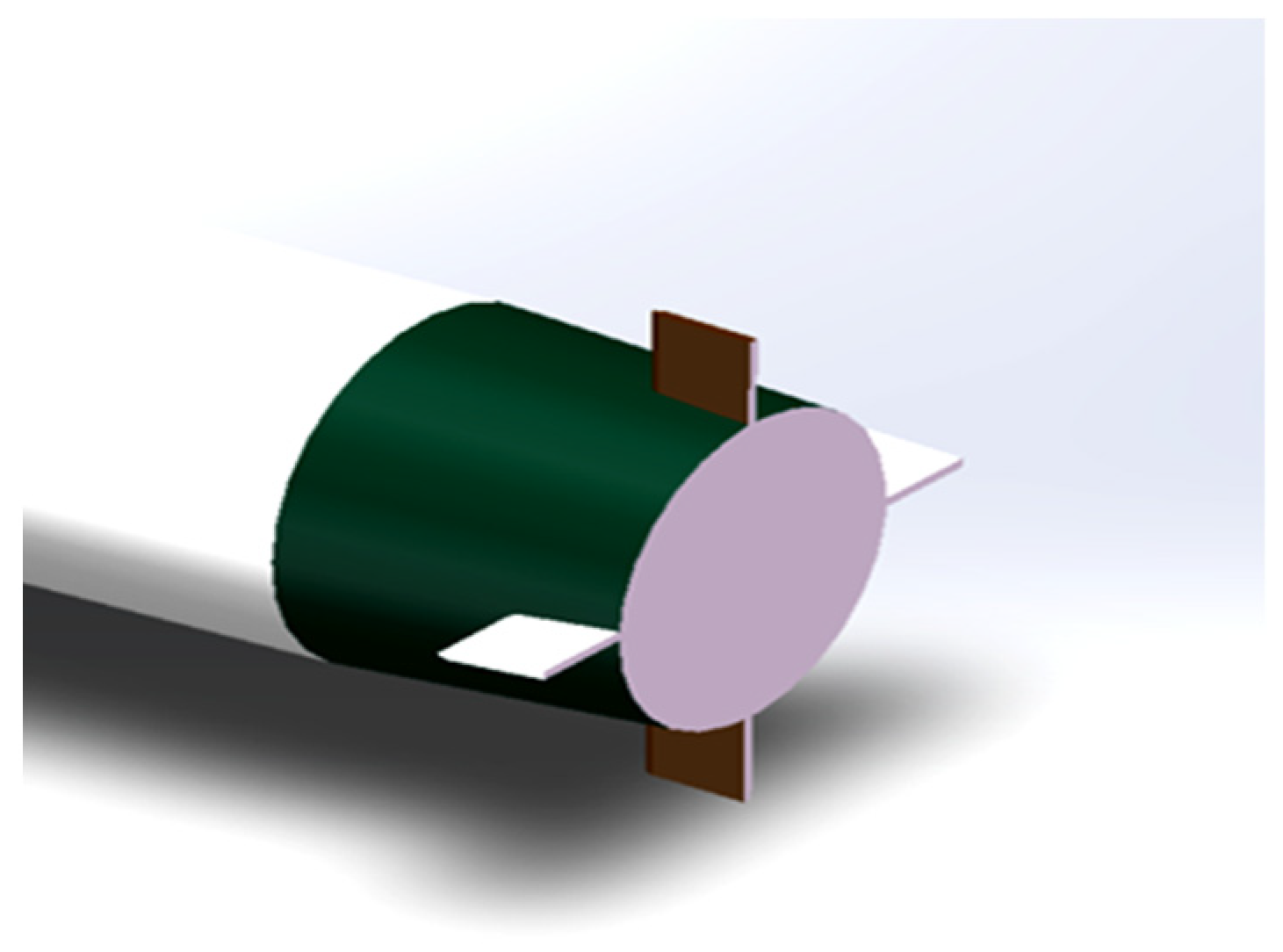
The control of the ballistic trajectory relies only on the rolling motion of control flaps under different phases. It comprises four rudders with fixed rudder deflection angles, as shown in Figure 2.
The model of roll control channel is established:
{ ω ˙ x a = M x z a + M xw + M c + M f I x a γ ˙ a = ω x a ω z tan φ 2
where ω xa is the rolling angular velocity of the control flaps around the x-axis; γ a represents the roll angle of the control flaps; M x z a and M xw are the gyroscopic moment and the polar damping moment of the control flaps component; M c is the control moment acting on the rudder. Here, M x z a and M xw are:
{ M x z a = 1 2 ρ ( v r ) 2 S L C x a δ a M xw = 1 2 ρ v r S L D C L p a ω x a
where ρ , v r , S , L , D , δ a are the air density, the velocity of the projectile relative to the air, the cross-sectional area, the length of the projectile, the diameter of the projectile, the deflection angle of the control flaps, respectively; C x a and C L p a are the coefficients for gyroscopic moment and polar damping of the control flaps component, respectively.

2.2. The Frictional Torque Model

It is assumed that various weak frictional torques can be neglected. The effects between the control flaps and the main body of the projectile during the relative rolling motion can be expressed as follows
M f = F f sgn ( ω x a ω x f ) [ k s + k v ( ω x a ω x f ) ]
where k s and k v are the coefficients of frictional resistance and relative motion resistance, respectively, k s , k v 0 , and they are fixed values, in which F f = ( F x + F y + F g ) . The three variables represent the total amount of aerodynamic drag, aerodynamic lift, and self-gravity of the projectile, respectively. These are expressed as follows
F x = f 1 ( C d , C d 0 , δ a , v , ω x 2 , ω y 2 , ω z 2 )
F y = f 2 ( C L a , v r , δ 2 , δ 1 , v p , ω x 2 , ω y 2 , ω z 2 )
F g = f 3 ( m , g , θ a , φ 2 )
where f 1 , f 2 and f 3 represent 3 × 1 matrices related to the variables; δ 1 and δ 2 represent the high and low attack angle and the directional attack angle; ω x 2 , ω y 2 and ω z 2 are the components of the wind speed in the velocity coordinate system along the x-, y-, and z-axes, respectively; transformation matrix from the O A to the O V and O A 2 is O A V and O A A 2 ; can be expressed as follows
= O A V O A A 2 [ 1 0 0 ]

2.3. The State Space of Whole System

In summary, considering the internal and external uncertainty disturbances in the system, such as the modeling error and aerodynamic parameter variations, the state variables of the system are defined as [ x 1 , x 2 ] T = [ γ a , ω x a ] T , the control variable is designed as u = M c , and the system model of the control channel model is transformed as follows:
{ x ˙ 1 = f 1 + Δ f 1 + ( g 1 ( x 1 ) + Δ g 1 ( x 1 ) ) x 2 + d 1 x ˙ 2 = f 2 + Δ f 2 + ( g 2 ( x 2 ) + Δ g 2 ( x 2 ) ) u + d 2
where d 1 and d 2 represent unknown comprehensive disturbances; Δ g 1 ( x 1 ) and Δ g 2 ( x 2 ) represent parameter uncertainties in the model. The control channel model can be simplified, and its specific form is given by the following
{ x ˙ 1 = f 1 + g 1 ( x 1 ) x 2 + E D 1 x ˙ 2 = f 2 + g 2 ( x 2 ) u + E D 2
where the error disturbance terms are transformed into equivalent disturbances E D 1 and E D 2 , E D 1 = Δ f 1 + d 1 + Δ g 1 ( x 1 ) x 2 , E D 2 = Δ f 2 + d 2 + Δ g 2 ( x 2 ) u , where f i and g i (   ) are functions defined as follows:
f i = [ f 1 f 2 ] = [ ω z tan φ 2 M f + M x z a + M x w I x a ] g i ( x ) = [ g 1 ( x 1 ) g 2 ( x 2 ) ] = [ 1 1 I x a ]
Here, the following is assumed:
(1) The rolling angle and angular velocity of motion attitude for the guided projectile can be measured, and the transmission of the command signal is smooth and continuous.
(2) The equivalent disturbance E D i ( i = 1 , 2 ) and its first-order derivative are assumed to be continuous and bounded E D i E D max .
According to the defined coordinate system and forces, the kinematic parameter model of the ballistic trajectory is established as follows
{ d θ a = 1 m v cos φ 2 ( ( F x + F y + F g ) [ 0 1 0 ] + F c cos γ a ) d ψ 2 = 1 m v ( ( F x + F y + F g ) [ 0 0 1 ] + F c sin γ a )
where θ a and ψ 2 represent the flight-path inclination angle and flight-path azimuth angle, respectively; F c = 1 2 ρ ( v r ) 2 S L C n d , where C n d is the lift coefficient of the control surface.
This study takes the system model as the research object under the preconditions of limited state variables x 1 , x 2 , the saturation and limitations of control variables u , as well as unknown bounded conditions φ 1 , φ 2 . The control quantity M c is obtained through the design of a sliding mode dynamic and a controller with optimal performance, which facilitate the rapid convergence of the roll angle and rolling angular velocity to a small neighborhood around zero within a finite time, thereby ensuring that the system is in a balanced and stable state ultimately.

3. The Design of Robust Roll Control System Based on Dynamics Model

A two-layer control architecture is constructed for the nonlinear roll control of the projectile model. Among them, the upper control is based on the dynamics model of the roll channel, and the control torque of the control flaps component is used as an input. The controller is constructed by designing the new global terminal sliding mode control algorithm and an adaptive approaching law to obtain the desired roll angle and rolling angular velocity. According to the desired impact point, the lower layer outputs the desired command control signals of the projectile in different stages of the whole trajectory.

3.1. The Relevant Lemmas

Lemma 1.
Consider a nonlinear system  x ˙ = f ( x ) , and assume the existence of a Lyapunov function  V ( x )  and parameters  α > 0 , β > 0 , 0 κ 1 , satisfying the following conditions:
(1)  V ( x )  is a positive definite function;
(2) The inequality  V ˙ + α V + β V κ 0  holds.
If the system state converges to the origin within a finite time and the convergence time depends on the initial state, then it satisfies
T ( x 0 ) 1 α ( 1 κ ) In ( α V 1 κ + β β )

3.2. The Design of the Upper Control Algorithm

The high-frequency vibration and the approach rate of rapid advance in the traditional nonlinear sliding mode control will influence the application of the control method and the control effect [19,20,21]. Accordingly, an adaptive sliding mode control algorithm is proposed based on the roll characteristics of the designed model, which is capable of achieving a rapid convergence rate while damping the vibration significantly.
The general nonlinear control system is as follows
x ˙ = f i ( x ) + g ( x ) u + d
where f ( x ) R n , g ( x ) R n × n and the elements in f ( x ) and g ( x ) are continuous, x = [ x 1 , , x n ] T R n denotes the state variables of the system, and d = [ d 1 , , d n ] T denotes the composite equivalent disturbance.
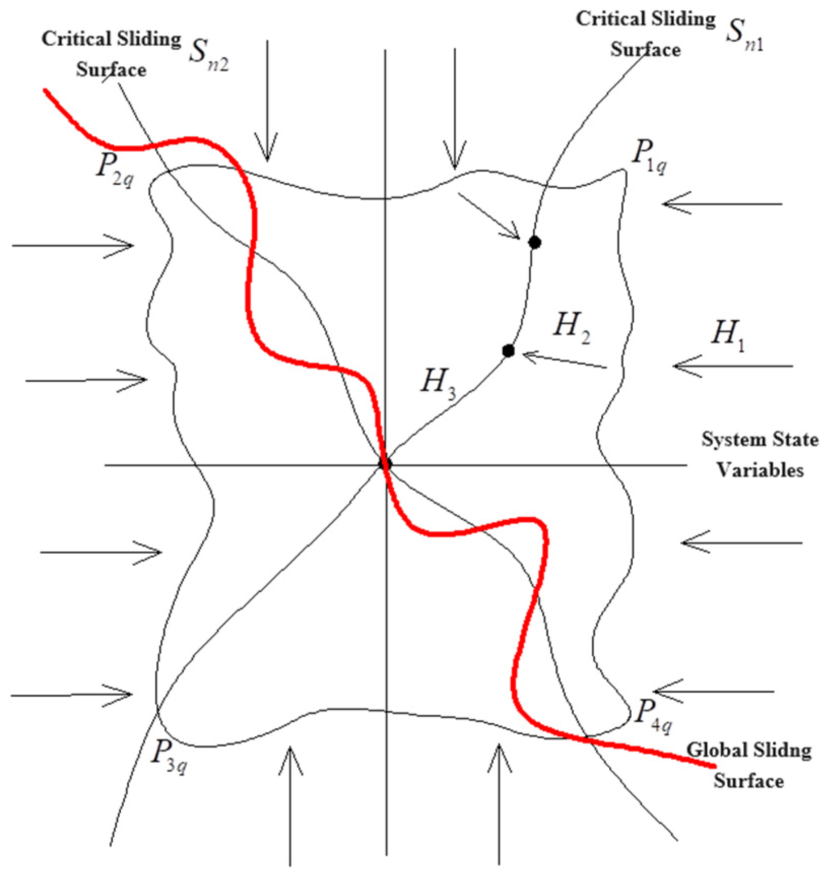
The theoretical framework of this proposed control theory is based on the assumption that a positive invariant set, designated as Q, exists within the process of the system approaching the origin. Furthermore, it is postulated that the acting scope of this region can be adjusted by tuning the parameters at any time. The whole convergence process is divided into two stages: The first stage involves the rapid approach of the system from an unknown direction to the critical buffer sliding surface. After reaching this surface, the final global sliding mode surface will adjust the parameter terms adaptively by calculating the state of the system. The second stage involves the motion process from crossing the critical surface to the final sliding mode surface. Due to the rapidity of the UGTSMC dynamics and the adaptive parameter, the system reaches the sliding mode surface accurately within the region Q until it moves to the origin on the sliding surface. This process design can alleviate the back surge caused by the fast approach rate to the sliding mode surface, which is “the unidirectional motion”. The structure of the UGTSMC also ensures a fast convergence process and improves the robustness of the system. The whole control process is shown in Figure 3.
The critical sliding mode dynamics are first given as follows
{ s n 1 = x ˙ + k 1 x n p 1 / q 1 s n 2 = x ˙ + k 2 x n p 2 / q 2
where x = [ x 1 , x n ] T R n , the condition k 1 , k 2 > 0 is used to ensure the stability of the critical sliding mode surface, and k 1 k 2 is used to avoid the overlap of the critical switching surface; p 1 > q 1 , p 2 > q 2 .
Taking suitable points p 1 q , p 2 q , p 3 q , p 4 q on the critical sliding surface so that the origin and its inclusion are inside the region, the system space within the critical surface can be s n 1 , s n 2 divided into four subspaces. In this case, it is known that s n 1 ( p 1 q ) = 0 , s n 1 ( p 2 q ) = 0 , s n 2 ( p 3 q ) = 0 , s n 2 ( p 4 q ) = 0 . Now, the region of the positive invariant set can be expressed as follows
Q = { ( x , x ˙ ) | p n q , n = 1 , 2 , 3 , 4 }
Within each subspace, the control system is forced to approach the sliding surface in a unidirectional motion. The adaptive parameter term is designed as follows:
C 1 i = { C 11 , s n 1 0 , s n 2 0 C 12 , s n 1 0 , s n 2 0 C 13 , s n 1 0 , s n 2 0 C 14 , s n 1 0 , s n 2 0 C 2 i = { C 21 , s n 1 0 , s n 2 0 C 22 , s n 1 0 , s n 2 0 C 23 , s n 1 0 , s n 2 0 C 24 , s n 1 0 , s n 2 0
where C = [ C 1 i , C 2 i ] represents the set of adaptive parameter terms for the global terminal sliding mode dynamics. Here, i denotes the number of subspaces i ( 1 , 2 , 3 , 4 ) , and each basic parameter term is assigned a value based on the corresponding calculation. One set of these can be represented as follows
{ C 11 = Δ I B 2 Δ I B 1 C 12 = Δ I B 1 Δ I B 2
where Δ I = ( D 2 B 2 ) ( D 1 B 1 ) , ( B 1 , B 2 , D 1 , D 2 ) are determined based on the values of the subdivided subspaces, such that each set of parameter terms corresponds to its respective subspace; K 1 B 1 B 2 = 1 , K 2 D 1 D 2 = 1 , K 1 and K 2 are constant values, where K 1 , K 2 > 0 . Here, Χ ( O ) = [ ( A 1 , A 2 ) , ( B 1 , B 2 ) , ( C 1 , C 2 ) , ( D 1 , D 2 ) ] , where each array of parameters is used to calculate the corresponding adaptive parameter terms, so the four subdivided subspaces have eight basic parameter terms.
In order to realize better control performance and compensate for uncertain equivalent disturbances effectively, the new sliding mode dynamics is designed as follows:
s c = x + α x ˙ + 1 β x p / q
where α and β are designed as the adaptive parameters, β 0 ; p , q are positive odd numbers, p q .
Theorem 1.
For the control channel model in the system space, the sliding mode dynamics designed is adopted. When the error term e ( t ) in the control variable is in the sliding mode surface, it can approach zero with a faster convergence rate and stronger robust performance in a limited time, so that the whole control system reaches a stable state.
Proof of Theorem 1.
When the control error term is completely convergent, that is, e ( t ) = 0, it can be written as
s c = e ( t ) + 1 β e ( t ) p / q + α e ˙ ( t ) = 0
It is assumed that the convergence time of the error is T e , that is e T e ( t ) = 0 , and the initial error term e T 0 ( t ) is bounded and non-zero. After moving the item and integrating it, we can obtain the following
T 0 T E E x = T 0 T E E 1 α 1 β x p / q
This sliding mode dynamics ensures that the velocity at which the system state deviates from s = 0 is mainly determined by x ˙ = 1 α 1 β x p / q . The dual coefficient setting of α and β guarantees the rapidity and stability of the convergence process. Therefore, the convergence time is as follows
T e = α β ( q q p e ( t ) 1 p q C )
Combined with Equation (19), the UGTSMC surface in the balanced state can be written as follows:
s c c = x 1 + C 1 i x 2 + 1 C 2 i x 1 p / q
In addition, in order to ensure that the control process has a smoother trend while ensuring a fast convergence speed, a proportional coefficient between the velocity and the relative distance is proposed. This can be expressed as follows
s ˙ q = k sgn ( s c c ) Δ V 1 Δ R r ( s c c )
where Δ R represents the relative distance between the projectile and the target, and it can be expressed as Δ R = f ( x , y , z , x c , y c , z c ) , where ( x , y , z ) and ( x c , y c , z c ) are the positions of the projectile and the target at the current time; Δ V represents the current velocity of the projectile.
The controller has a better control performance and can theoretically be realized by increasing the value of r or decreasing the value of k within a finite time. The effect of k sgn ( s c c ) is to drive the control variables to approach the sliding mode surface at a faster convergence rate while damping the step characteristic of the sign function. The setting of the proportional coefficient also allows the system to relatively suppress the back surge caused by excessive convergence speed, thereby reducing the disturbance impact on the control system. The aforementioned factors contribute to the overall robustness of the system. □

3.3. The Lower-Layer Control Command

The lower control outputs the command signals in different motion stages by calculating the motion state and relative position of the projectile according to the different target sets.
F n = { n 1 , T < T c 1 f ( n 2 ) , T c 1 T < T c 2 f ( n n ) , T c n T < T n
where T represents the motion time; n 1 is the output instruction when it is uncontrolled; T c 1 and T n represent the time points of the starting controlling and ending control state in the whole control process, respectively; T c i and f ( n i ) , i = 1 , 2 n represent the end control time points and the control command output in different control stages, respectively, which can be function items or fixed values according to the different motion states.

3.4. The Designed Robust Autopilot Based on the Control Algorithm

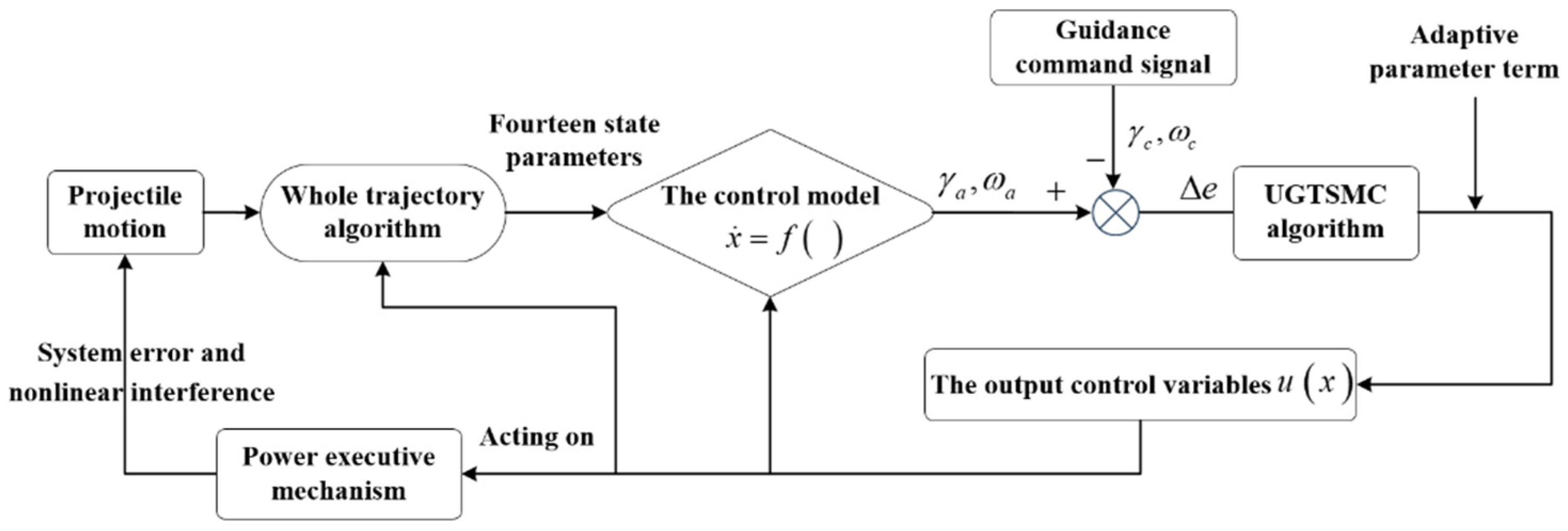
The dynamic trajectory of the projectile during its motion is controlled by the roll angle of the control flaps. A robust roll autopilot is designed by combining the sliding mode surface with the adaptive parameter items, so that the roll angle can be quickly and stably tracked to the guidance command. Set the commanded roll angle of the control flaps as γ c and the commanded rolling angular velocity as ω c . The process is shown in Figure 4.
Therefore, the tracking error of the roll angle is defined as e 1 = γ a γ c , e 2 = γ ˙ a γ ˙ c , and the error model of the roll autopilot can be represented as follows:
{ e ˙ 1 = e 2 e ˙ 2 = M xz + M x w + M c + M f I x a γ ¨ c
Based on the reconstructed error dynamic model of the control channel, a global terminal sliding surface is designed, and its derivation can be expressed as follows:
s ˙ s = C 1 i ( γ ¨ a γ ¨ c ) + γ ˙ a γ ˙ c + 1 C 2 i p q ( γ a γ c ) p / q 1 ( γ ˙ a γ ˙ c )
The controller for the roll channel is designed in combination with Equation (24) as follows
u = 1 C 1 i g 2 [ C 1 i ( f 2 y ¨ c ) + k sgn ( s s ) + x ˙ 1 + C 2 i q p e p / q 1 e ˙ + r s s y ˙ c ]
Proof. 
Consider choosing the following Lyapunov function
V = 1 2 s s 2
The derivation of the time using V and substituting in
V ˙ = s 2 s ˙ 2 = [ γ a γ c + α ( γ ˙ a γ ˙ c ) + 1 w k 2 ( γ a γ c ) p / q 1 ] [ w k 1 ( γ ¨ a γ ¨ c ) + γ ˙ a γ ˙ c + 1 w k 2 p q ( γ a γ c ) p / q 1 ( γ ˙ a γ ˙ c ) ] [ γ a γ c + α ( γ ˙ a γ ˙ c ) + 1 w k 2 ( γ a γ c ) p / q 1 + Δ φ ] [ k tanh ( s 2 ) r ( s 2 ) ] = [ s 2 ] [ k tanh ( s 2 ) r ( s 2 ) ]
Therefore, it follows that from Lemma 1:
V ˙ + 2 r V 1 / 2 + 2 h V 0
Thus, the control system can converge to any small neighborhood near zero in finite time, with the convergence time being:
T ( x 0 ) 1 α In ( 2 α V + 2 β 2 )
Theorem 2.
For the dynamic model (10) and (11) of the roll channel of a guided projectile, the designed sliding mode controller (28) can make the error of the roll angle and rolling angular velocity converge to zero in a very short time. There will be no instability or vibration, so as to achieve steady tracking with the command signal.

4. The Simulation Verification

This section focuses on the model of the roll channel and the whole motion trajectory. Considering the modeling errors and unknown internal and external disturbances, the control effect of the system and the motion attitude of the projectile are simulated and calculated during the control process. In addition, the aerodynamic parameters of the projectile under different operating conditions were obtained using the computational fluid dynamics software Fluent 2022. The simulation model is shown in Figure 5. Here, only the parameter values at 1.0M are provided. C d , C n d , C d 0 , C L p a , C x a and C L a are set as 0.4978, 0.7581, 8.0112, −0.006068, 0.0578, and 2.5485, respectively. The values of the basic parameters of the projectile and the guidance control parameters are presented in Table 1 and Table 2, respectively.

4.1. The Control Effects of the Roll Channel

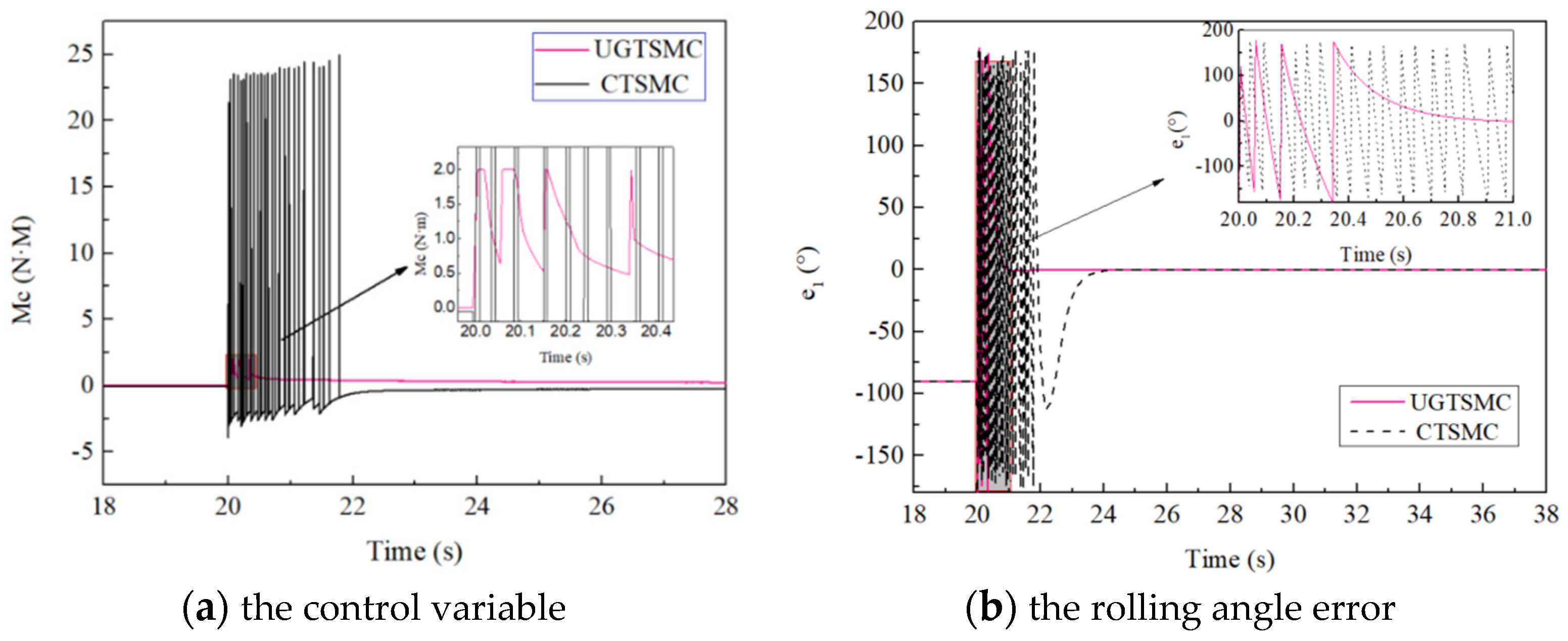
Considering the special structure and motion characteristics of the projectile, the guidance strategy is designed to initiate the controlled state of the guidance signal input at 20 s of motion (that is, when it moves near the highest point of the trajectory). In addition, the CTSMC (conventional terminal sliding mode control) method with no switching term and effective chatter suppression is designed to compare the control effect with the new method. The figure illustrates the variation curves of the control variable and the roll angle error for the UGTSMC and CTSMC. The sliding surface and controller of the CTSMC are designed as follows
{ s t = x 2 + r 2 x 1 z q / z p u t = 1 g 2 [ f 2 y ¨ c + z q r 2 z p e ( z q z p ) / z p e ˙ + A ]
where r 2 > 0 and is set to be 3; both z q and z p are positive odd numbers, z q > z p ; the z q , z p and A are set to be 7, 5 and 3.
It is evident from Figure 6a that both control methods can achieve a stable state on the control variable for a period of time after starting control. However, compared with the CTSMC (Hsinchu, Taiwan), the UGTSMC does not produce large singular values or strong vibration in the whole control process, reducing the high energy consumption or system instability caused by it. The control torque is kept within 2.0 NM during the whole motion process, and the control torque is only 0.9 NM in the steady state. The limited input of the control variable also makes the control system more suitable for the actual engineering applications of the projectile. As shown in Figure 6b, the guidance control error of the proposed control algorithm converges smoothly to zero within 0.9 s after starting control, and the error is basically kept at 0° during the remaining movement time, which ensures that the roll angle of the control flaps is always in high agreement with the roll angle of the guidance command. There is no fluctuation or large error in the whole convergence process, which further ensures the accuracy of the control effect. The new sliding mode dynamics here plays a role in accelerating the convergence rate, and the introduction of adaptive parameter terms and adaptive convergence law after crossing the critical sliding mode surface also converge to the sliding mode surface in a relatively stable state.

4.2. The Control Effect Analysis of the Motion Attitude

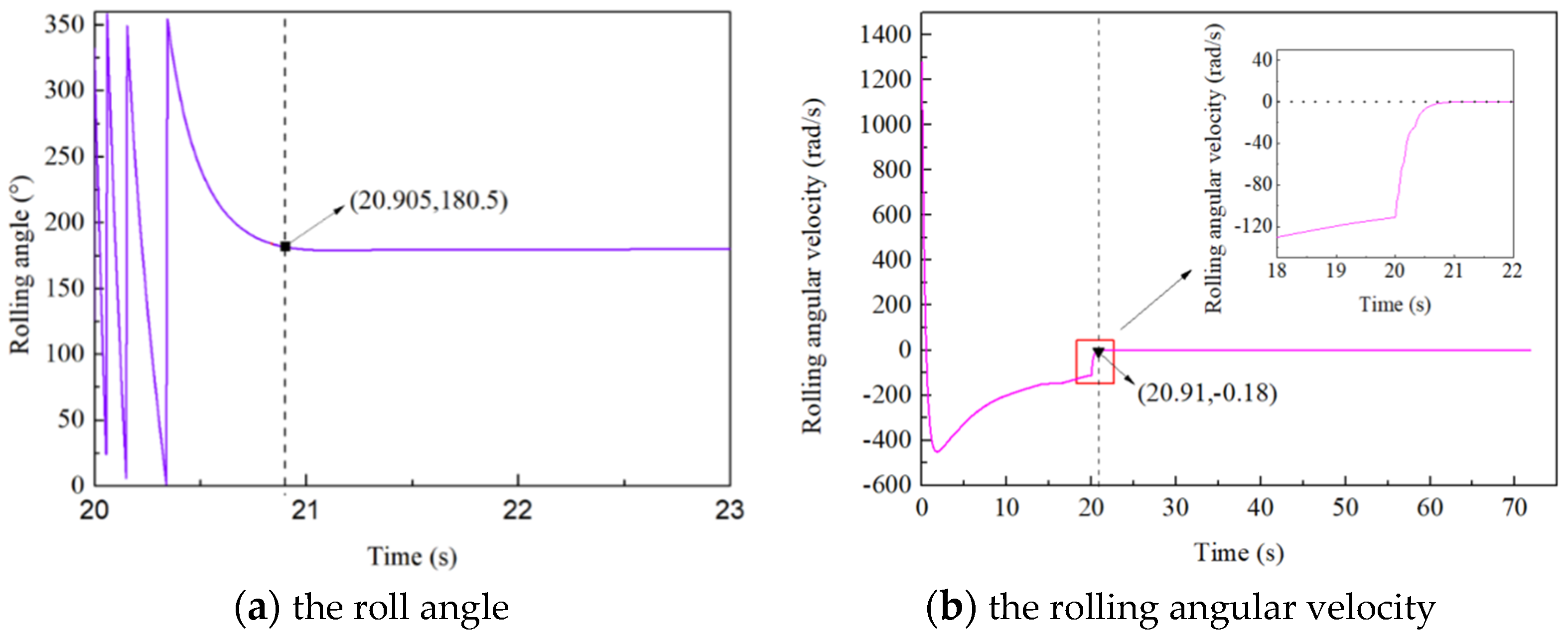
Figure 6 shows the variation curves of two state variables, namely the roll angle and the rolling angular velocity of the control flaps. As illustrated in Figure 7a, it can be observed that the actual roll angle achieves a stable control effect within 0.9 s after starting control. Throughout the entire process, the projectile rotates less than four cycles, which significantly improves the response speed to achieve a stable state. During this period, the rolling angular velocity of the control flaps is also reduced from 118 rad/s to 0.18 rad/s due to the control torque, and it is basically maintained at zero in the remaining motion time. This guarantees that the control flaps will not exhibit any sudden or erratic movements, while also determining the actual direction of motion based on the output value of the roll angle.
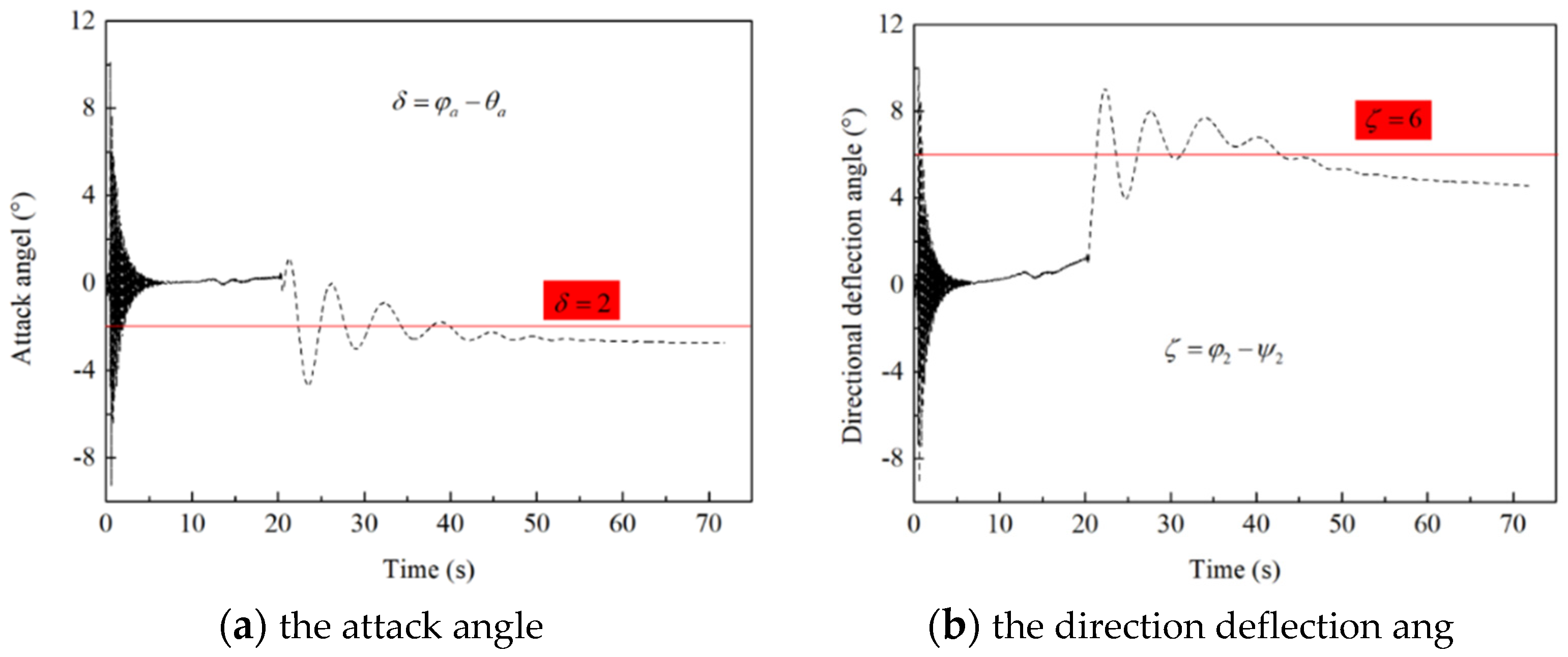
The change curves of motion attitude with the projectile during the control process are also given, as shown in Figure 8. As can be seen, the change trend of the attack angle and the direction deflection after starting control are smooth and slow. And the maximum value of the attack angle and direction deflection is 4 degrees and 8 degrees, respectively. The positive and negative values only indicate the movement direction of the projectile, and the changes in the values are within the controllable range of the ballistic deviation correction. In the second half of the motion, the values of the two variables are finally in a relatively steady state, maintained at −2 degrees and 6 degrees. The smooth change trend and the final steady state mean that the projectile will not be destabilized or dropped in the control process.
In addition, considering that excessive modeling errors and unknown strong external disturbances may cause the system to diverge or lead to significant deviations, it is important to verify the anti-jamming capability of the designed controller under large disturbances. Therefore, the strong disturbances added to each stratum of the control channel are designed as follows
{ E D 1 = 0.3 sin ( 4 t ) + 0.15 cos ( 3 t ) E D 2 = 0.2 cos ( 2 t ) + 0.4 sin ( t )
where E D 1 and E D 2 are the equivalent perturbations for the angular velocity channel and the roll angle channel, respectively.
Figure 9a shows a partial estimation diagram of the model equivalent disturbance. From the figure, it can be seen that the two sets of disturbances vary over time within a range of ±0.6, and both are in a relatively strong disturbance state. However, it can be observed from Figure 9b (that is, the error graph of the roll angle based on this disturbance) that the entire control system begins to approach the stable state at 1.0 s, and it is not until 6.0 s that the actual roll angle is fully matched with the command, at which point the steady state is realized. The required time is relatively long, and the convergence speed is relatively slow, which can be attributed to the unknown strong disturbances in the model. However, there are no vibration or control divergences throughout the process, and the convergence process is also in a relatively smooth change.

4.3. The Simulation Calculations under Different Control Parameter and Guidance Strategies

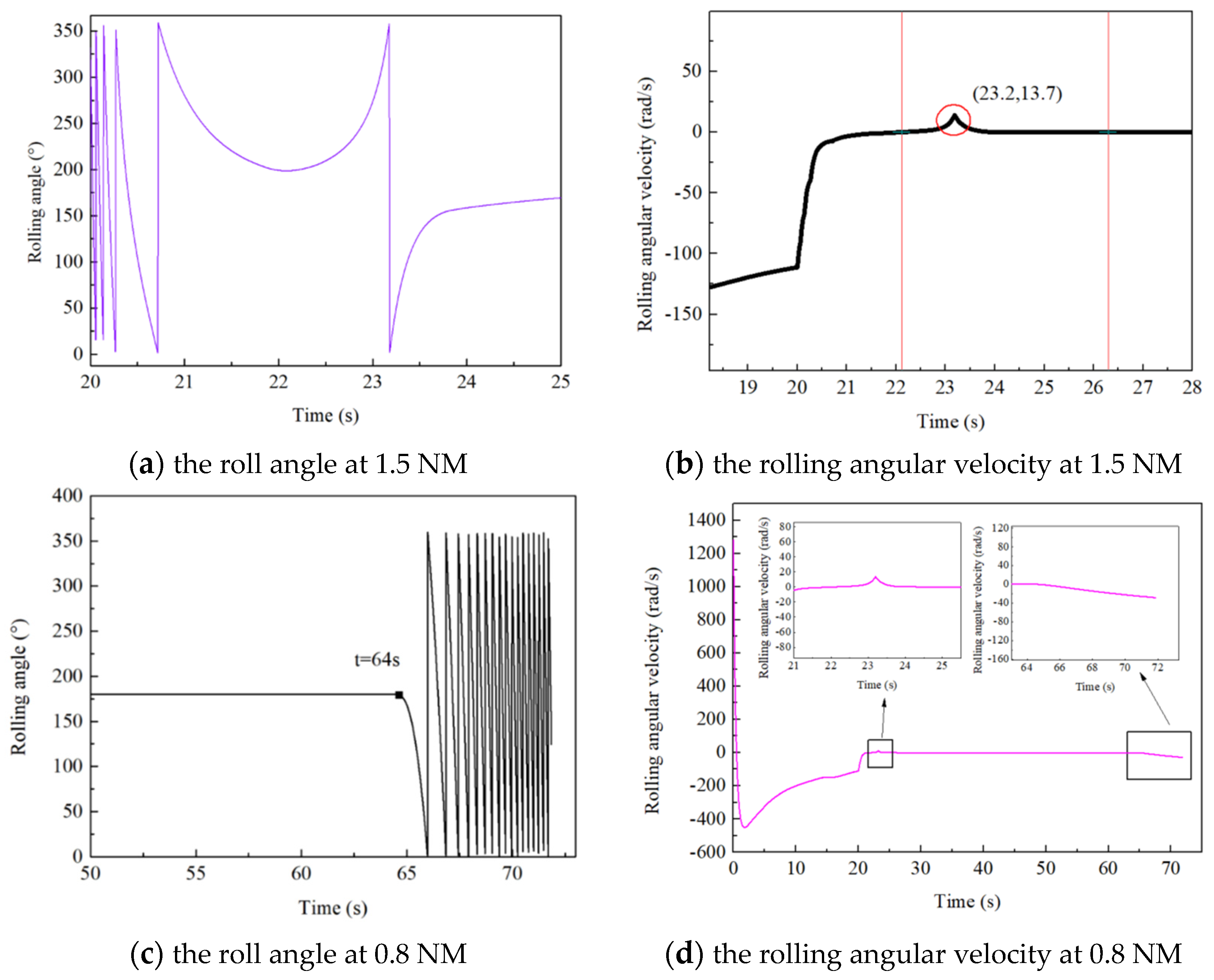
Considering the special engineering constraints in this model and further aligning with practical design requirements, the limitation of the control torque was designed as 1.5 NM and 0.8 NM, respectively, so as to observe the change in the control effect under different values.
As seen from Figure 10a, the roll angle undergoes convergence motion with a steady state after the spin reduction effect of the control torque and then floats within a small range of the steady-state neighborhood. The time required for the system to reach the steady control effect is 6.6 s. The long time required and the inability to precisely control the roll angle show the influence of the weak output control torque on the actual control effect. In addition, compared with the curve of the roll angle when the control torque is 2.0 NM, it can be seen that due to the reduced output control torque, the projectile rotates one more cycle during the control convergence process. Therefore, when it is close to the steady state, the roll angle has a convergence process of reverse roll and then reaching the steady state.
A partial change curve of the roll angle and the rolling angular velocity change rules are shown in Figure 10c,d. It can be clearly seen that in addition to the above situation, at the end of the trajectory (when T is greater than 64 s), the projectile suddenly appears to make 360° of continuous rolling movement. The rolling angular velocity at this time increases from stable near 0 rad/s to 36 rad/s in the corresponding time. At this point, the projectile has transitioned from a controlled state to an uncontrolled state. This instability is a consequence of the insufficiently sized set control torque, which is unable to be replicated in the model at the conclusion of the motion.
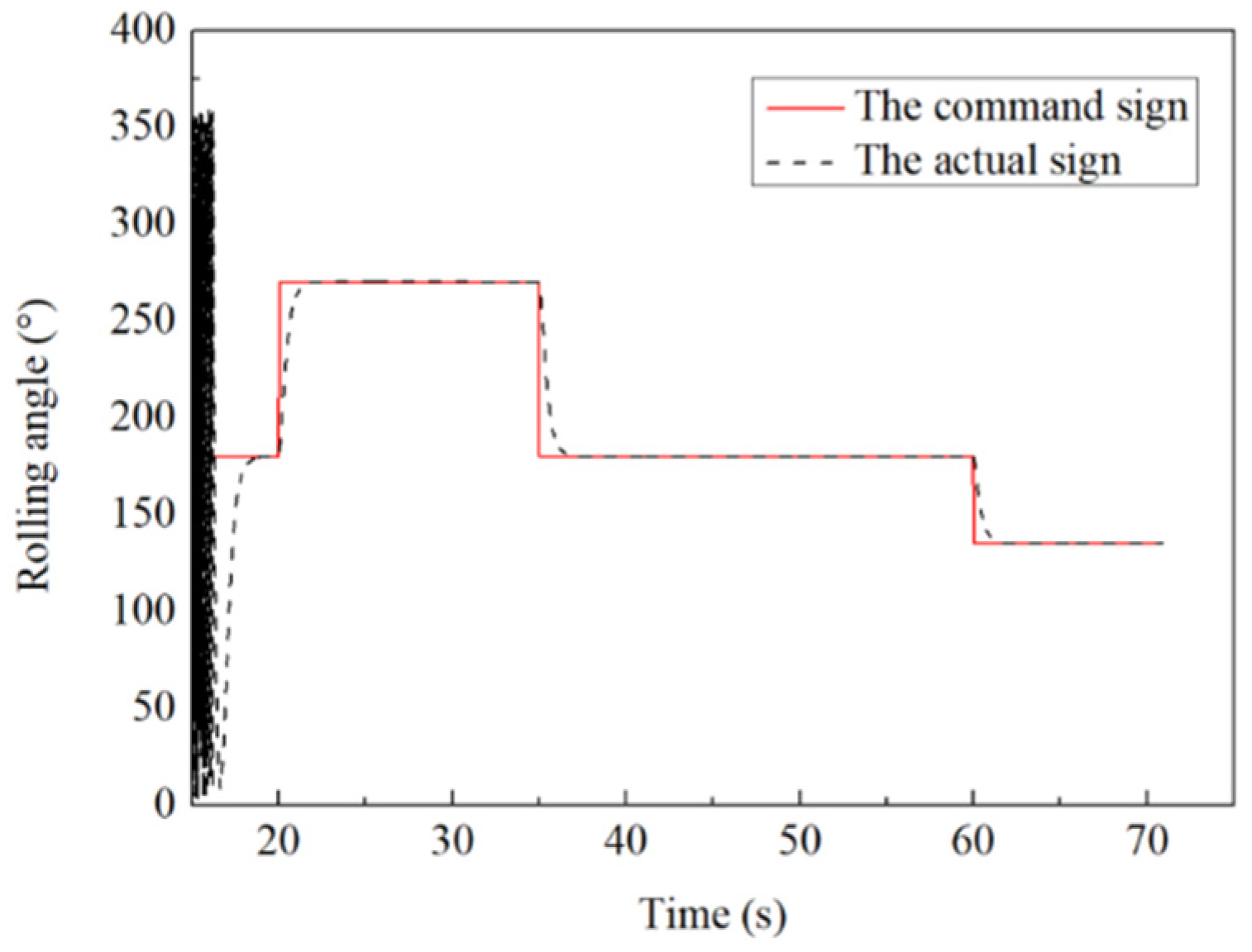
The varied guidance strategies pose a greater challenge to the effectiveness of the control system and better match the actual motion of the projectile. Therefore, the design scheme is as follows: Before the projectile reaches its highest point, the control moment is maintained towards the range direction at 180°. In the second half of the trajectory, the guidance command signals in both directions of deviation and range are adjusted successively and simultaneously. Accordingly, the T c 1 , T c 2 and T c 3 are set to 20, 35 and 60. The f ( n 2 ) , f ( n 3 ) and f ( n n ) are set to 270, 180 and 135. The simulation results are shown in Figure 11. It can be observed that the roll angle remains stable in a roll state before control initiation. After starting control, the actual roll angle consistently aligns with the guidance command signal, and the tracking error is found to be negligible. As a result, the final hit accuracy of the projectile is guaranteed. The transition between different setting stages also achieves tracking of the command signal within a short period of time, with no phenomenon of angle fluctuation back and forth.

5. Conclusions

In this study, a system model of a projectile structure with superior aerodynamic characteristics is designed. To address the nonlinear control issues resulting from the model dynamic coupling and the conventional sliding mode vibration, a global terminal sliding mode control algorithm with a uniaxial approach state is proposed. The sliding mode controller is designed by combining the guidance command signals. The numerical simulation results indicate the following:
(1) This control method can achieve tracking of the command signal within 0.9 s and then maintain a continuous and stable control effect during the remaining movement. There is no vibration or instability during the whole motion process and the large equivalent disturbance state, which confirms that the designed controller has both better rapidity and stronger robustness. In addition, the control system can still realize the precise control effect under different guidance strategies, which is conducive to ensuring the smooth attitude of the projectile while greatly improving the precision hitting efficiency of the target.
(2) During the whole control process, the attack angle and directional deflection of the projectile are basically kept at about −2 degrees and 6 degrees, respectively. The small change amplitude and smooth change process ensure that the projectile has a good motion attitude, so that it will not cause a large impact or uncontrolled state on the projectile in the control stage.
(3) Based on the design model, the optimal value of the control torque is 2.0 NM; the limited and small input of the control torque during the whole motion process ensures that the designed control system has a certain practical engineering value.
The designed control method has absolute superiority compared to traditional terminal sliding mode methods and solves the problems of “slow response” and “difficult control” in the roll control channel of guided projectiles under disturbance conditions, which confirms that it has superior rapidity and strong robustness.

Author Contributions

The conceptualization, methodology, validation, data curation, writing—original draft preparation and review and editing, S.G.; the project administration and the funding acquisition, L.W.; the supervision, J.F. All authors have read and agreed to the published version of the manuscript.

Funding

The support for this article comes from the national preliminary equipment projects. The number of this project is JA2020111.

Data Availability Statement

The datasets generated and/or analyzed during the current study are available from the corresponding author on reasonable request.

Conflicts of Interest

The authors declare no conflicts of interest.

Abbreviations

O E ground coordinate system
O V ballistic coordinate system
O A projectile axis coordinate system
O B projectile body coordinate system
O A 2 second axis coordinate system
M a , M b the corresponding acting moments by the airflow
ω x f the rolling angular velocity of the projectile’s main body around the x-axis
ω xa the rolling angular velocity of the control-flaps around the x-axis
ω y , ω z the rolling angular velocities of the projectile around the y-axis and z-axis
M xz the polar damping moment of the projectile around the x-axis
M x z a the polar damping moment of the control-flaps component around the x-axis
M k , M c k the components of the aerodynamic moment of the projectile’s main body and the control moment in the y-axis and z-axis directions
M f the frictional resistance moment
M xw the gyroscopic moment of the control-flaps
M c the control moment acting on the rudder
I y the equatorial moment of inertia
I xf the polar moments of inertia of the projectile’s main body
φ 2 the azimuth angle of the projectile’s axis
γ f the roll angle of the main body component
γ a the roll angle of the control-flaps
ρ , v r the air density and the velocity of the projectile relative to the air
S , L the cross-sectional area and the length of the projectile
D , δ a the diameter of the projectile and the deflection angle of the control-flaps
C x a , C L p a the coefficients for gyroscopic moment of the control-flaps and polar damping of the main body
k s , k v the coefficients of frictional resistance and relative motion resistance
F x the total amount of aerodynamic drag
F y the total amount of aerodynamic lift
F g the total amount of self-gravity
ω x 2 , ω y 2 , ω z 2 the components of the wind speed in the velocity coordinate system around x, y, and z axis
d 1 , d 2 the unknown comprehensive disturbances;
Δ g 1 ( x 1 ) , Δ g 2 ( x 2 ) the parameter uncertainties in the model
E D 1 , E D 2 the equivalent disturbances
θ a , ψ 2 the flight-path inclination angle and flight-path azimuth angle
C n d the lift coefficient
p 1 q , p 2 q , p 3 q , p 4 q the suitable points on the critical sliding surface
k 1 , k 2 the coefficient of the critical sliding mode surface
Q the region of the positive invariant
s n 1 , s n 2 the critical sliding surface
C = [ C 1 i , C 2 i ] the adaptive parameter terms for the global terminal sliding mode dynamics.
( A 1 , A 2 ) , ( B 1 , B 2 ) , ( C 1 , C 2 ) , ( D 1 , D 2 ) eight basic parameter terms on the four subdivided subspaces
T e the convergence time of the error
e T 0 ( t ) the initial error term
α , β the dual coefficient setting of the sliding surface
Δ R the relative distance between the projectile and the target
Δ V the current velocity of the projectile.
T the motion time
n 1 the output instruction when it is uncontrolled
T c 1 , T n the time points of starting controlling and ending control state in the whole control process
T c i the end control time points in different control stages
f ( n i ) the control command output in different control stages
γ c the commanded roll angle of the control-flaps
ω c the commanded rolling angular velocity
e 1 the tracking error of the roll angle
C d the drag coefficient
C d 0 the zero-lift drag coefficient
C L a the lift coefficient

References

  1. Wang, Z.Y.; Shi, J.G.; Chang, S.J.; Li, Y.; Chen, Q.; Yi, W.; Wang, X. Review on development of technology of trajectory correction projectile. J. Ballist. 2021, 33, 1–12. [Google Scholar]
  2. Li, S.H.; Wang, X.Y.; Ding, S.Y. Research on the Theory and Application of Sliding Mode Control; Science Press: Beijing, China, 2022; pp. 28–55. [Google Scholar]
  3. Pang, B.C.; Jiang, S.J.; Zhao, C. Research on dynamic aerodynamic characteristics of spin tail canard layout projectiles and arrows based on numerical virtual flight. J. Proj. Arrows Guid. 2021, 41, 101–110. [Google Scholar]
  4. Zhong, Y.; Wang, L.M.; Li, Y. Calculation model of normal force of canard on spin stabilized two-dimensional trajectory correction projectile. J. Ballist. 2019, 31, 48–54. [Google Scholar]
  5. Ma, G.L. Control effect analysis of dual-spin projectile based on modified mass point trajectory model. Trans. Beijing Inst. Technol. 2019, 39, 777–783. [Google Scholar]
  6. Zhao, X.X.; Shi, J.G.; Wang, Z.Y. Study on angular motion characteristics and control stability with the fixed canard dual spin projectile. J. Harbin Inst. Technol. 2022, 54, 123–131. [Google Scholar]
  7. Fang, X.; Yang, W.J.; Fan, Z.; Zhang, K. Multi-Power Sliding-Mode Control for Hypersonic Vehicles. Solid Rocket Technol. 2018, 41, 258–264. [Google Scholar]
  8. Wang, C.; Wang, X.G. Terminal slip mode control of hypersonic guided projectiles. Syst. Eng. Electron. 2020, 42, 2859–2866. [Google Scholar]
  9. Wang, C.; Ma, J.J.; Zhang, X.L.; Wang, X.G.; Wu, Y.F. Backstepping sliding mode control of hypersonic guided projectiles based on disturbance compensation. J. Artill. Firing Control 2023, 12, 12–21. [Google Scholar]
  10. Jiang, S.; Tian, F.Q.; Sun, S.Y. Integrated design of spatial multi-constraint guidance and control for rolling naval gun guided projectiles. J. Aeronaut. 2019, 40, 32–41. [Google Scholar]
  11. Han, J.X.; Ma, F.Y.; Dian, S.Y. Terminal sliding mode control for uncertain systems based on nonlinear disturbance observers. Electro-Opt. Control 2020, 27, 29–34. [Google Scholar]
  12. Yin, T.T.; Jia, F.X.; Yu, J.Y.; Wang, X.O. Robust adaptive control of roll position of fixed rudder for dual-spin projectile with improved LuGre friction model. Acta Armamentarii 2019, 40, 2425–2432. [Google Scholar]
  13. Zhao, Z.H.; Cao, D.; Yang, J.; Wang, H. High-order sliding mode observer-based trajectory tracking control for a quadrotor UAV with uncertain dynamics. Nonlinear Dyn. 2020, 102, 2583–2596. [Google Scholar] [CrossRef]
  14. Xing, B.N.; Du, Z.H.; Du, C.X. Review of two-dimensional ballistic modified projectiles and their guidance control technology. J. Natl. Univ. Def. Technol. 2021, 43, 53–68. [Google Scholar]
  15. Zhang, X.; Yao, X.X. Research on roll control of fixed-wing dual-rotor correction components. Trans. Beijing Inst. Technol. 2020, 40, 386–395. [Google Scholar]
  16. Sherstinsky, A. Fundamentals of recurrent neural network and long short-term memory network. Nonlinear Phenom. 2020, 4, 132–142. [Google Scholar] [CrossRef]
  17. Lewis, F.W.; Jagannatan, S.; Yesildirak, A. Neural Network Control of Robot Manipulators and Non-Linear Systems; CRC Press: Boca Raton, FL, USA, 2020; pp. 1–12. [Google Scholar]
  18. Han, Z.P. Exterior Ballistics of Projectiles and Rockets; Beijing Institute of Technology Press: Beijing, China, 2008; pp. 25–39. [Google Scholar]
  19. Yin, T.T. Research on the Rolling Control System of Fixed Canard Rudder with a Spaced Duck Rudder Ballistic Correction Projectile; Nanjing University of Science and Technology: Nanjing, China, 2020; pp. 65–89. [Google Scholar]
  20. Yang, Z.W.; Wang, L.M. Movement characteristics of a dual-spin guided projectile subjected to a lateral impulse. Aerospace 2021, 8, 309. [Google Scholar] [CrossRef]
  21. Wang, Y. Analysis of Guidance and Corrective Strategy for a Spin-Stabilized Projectile Equipped with Fixed Canards; Nanjing University of Science and Technology: Nanjing, China, 2019; pp. 22–33. [Google Scholar]
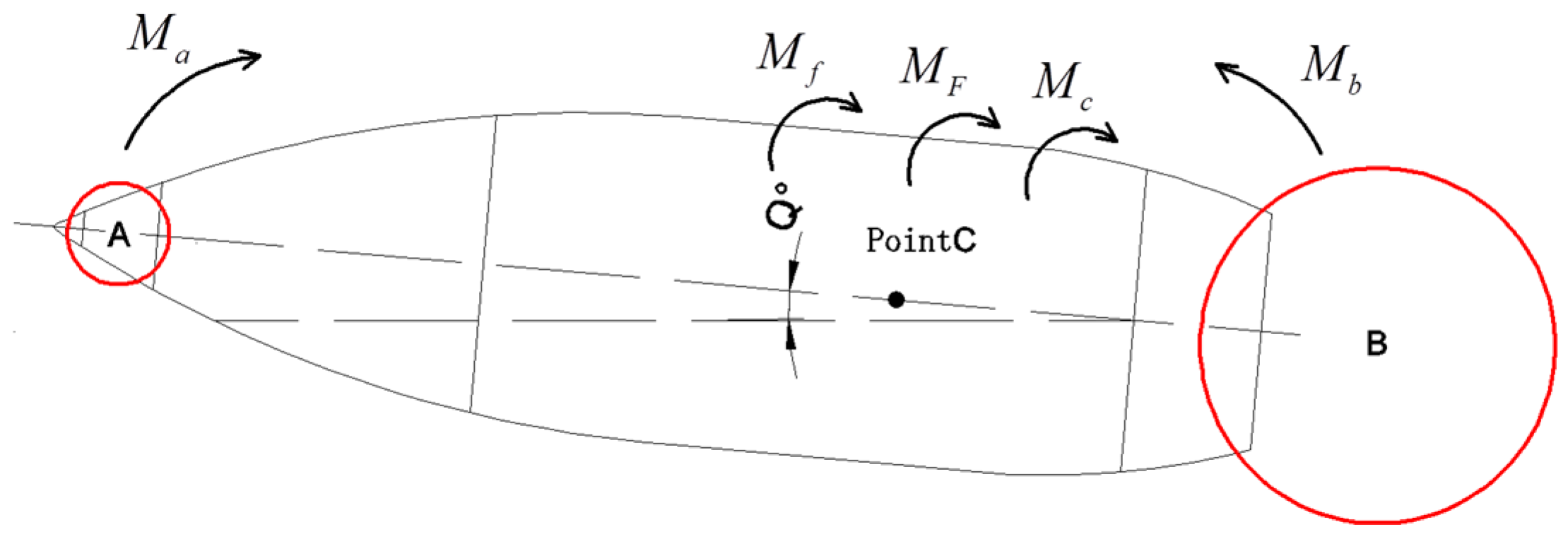
Figure 1. Control flap location diagram of a different projectile.
Aerospace 11 00683 g001
Figure 2. A sketch of the configuration with the control surfaces.
Aerospace 11 00683 g002
Figure 3. The whole convergence process of the designed control algorithm.
Aerospace 11 00683 g003
Figure 4. A structure diagram of the designed autopilot.
Aerospace 11 00683 g004
Figure 5. The flow field simulation model.
Aerospace 11 00683 g005
Figure 6. Comparison of the control effect.
Aerospace 11 00683 g006
Figure 7. The change curves of the state variable.
Aerospace 11 00683 g007
Figure 8. The change curves of the motion attitude.
Aerospace 11 00683 g008
Figure 9. The anti-jamming performance of the system.
Aerospace 11 00683 g009
Figure 10. The control effect at different control torques.
Aerospace 11 00683 g010
Figure 11. The system tracking performance in actual condition.
Aerospace 11 00683 g011
Table 1. The basic parameters of the projectile.
ParameterValueParameterValue
m / kg 22.15 I x a / ( kg m 2 ) 0.0034
L / m 0.668 I x f / ( kg m 2 ) 0.041
D / m 2 0.122 I y / ( kg m 2 ) 0.5069
Table 2. The setting parameters for the guidance control strategy.
ParameterValueParameterValueParameterValue
k 1 2 p 5 q 1 9
k 2 1 q 3 q 2 7
p 1 7 K 1 2 k 1
p 2 5 K 2 1 r 4
Disclaimer/Publisher’s Note: The statements, opinions and data contained in all publications are solely those of the individual author(s) and contributor(s) and not of MDPI and/or the editor(s). MDPI and/or the editor(s) disclaim responsibility for any injury to people or property resulting from any ideas, methods, instructions or products referred to in the content.