Article

Preliminary Sizing of High-Altitude Airships Featuring Atmospheric Ionic Thrusters: An Initial Feasibility Assessment

Department of Aerospace Science and Technology, Politecnico di Milano, Via La Masa 34, 20156 Milano, Italy
*
Author to whom correspondence should be addressed.
Aerospace 2024, 11(7), 590; https://doi.org/10.3390/aerospace11070590
Submission received: 28 June 2024 / Revised: 15 July 2024 / Accepted: 17 July 2024 / Published: 19 July 2024

Abstract

:
When it comes to computing the values of variables defining the preliminary sizing of an airship, a few standardized approaches are available in the existing literature. However, when including a disruptive technology in the design is required, sizing procedures need to be amended, so as to be able to deal with the features of any additional novel item. This is the case of atmospheric ionic thrusters, a promising propulsive technology based on electric power, where thrusters feature no moving parts and are relatively cheap to manufacture. The present contribution proposes modifications to an existing airship design technique, originally conceived accounting for standard electro-mechanical thrusters, so as to cope with the specific features of new atmospheric ionic thrusters. After introducing this design procedure in detail, its potential is tested by showing results from feasibility studies on an example airship intended for a high-altitude mission. Concurrently, the so-obtained results allow the demonstration of the sizing features corresponding to the adoption of atmospheric ionic thrusters at the current level of technology, comparing them to what is obtained for the same mission when employing a standard electro-mechanical propulsion system.

1. Introduction

Lighter-than-air (LTA) flying craft, currently employed or still in a design stage, are usually lofted according to two major paradigms, namely as passively controlled, non-propelled balloons or as actively controlled, propelled airships. In the latter case, existing realizations invariably make use of rather standard propulsion techniques, with propellers coupled to piston engines or electric motors [1,2].
As is widely known [3,4,5], among the missions that LTA craft can cover, high-altitude observation missions are particularly interesting since the peculiar atmospheric conditions—especially the good predictability and overall stability of the thermodynamic and chemical state of the atmospheric mixture at altitudes around 18–20 km from the ground—potentially allow the overcoming of the inherent weaknesses of these platforms, primarily bound to controllability [6,7,8,9], unfolding their potential as an alternative to more expensive aircraft and satellites. Currently, passively controlled balloons are employed for several missions, especially for gathering signals or measurements during the ascent or for relatively short-term signal relay in the higher layers of the atmosphere [10,11,12]. However, for image collection and signal relay while in a station-keeping attitude, active control and propulsion are required, at least to counter the stratospheric wind encountered at the target stationing altitude. The latter mission, often referred to as high-altitude pseudo-satellite (HAPS), is of special relevance for both civil and military purposes, yet it is very challenging from the design standpoint [13,14,15,16,17]. First, the exposure to high energy intensity and a chemically active gaseous mixture tends to degrade materials quicker than in other design problems in the aeronautical domain. Second, the design of the propulsion system for a high time between overhauls (TBO) so as to allow an almost-permanent deployment at altitude may become an issue similar to the case of satellites, given the articulated and uneasy procedures required for a safe descent and recovery, and for the re-deployment as well, which an overhaul would invariably require. As a matter of fact, high-altitude airships (HAA) are actually still in their infancy, with conceptual and experimental machines proposed and tested over the years [18,19,20], but with no standardized model having entered production to date.
To the aim of increasing the TBO of HAA platforms while additionally starkly decreasing the chance of detection, novel technology has been proposed for generating thrust, namely atmospheric ionic thrusters (sometimes referred to as ion-plasma thrusters) [21,22,23,24,25]. Working on the principle of ionizing air in proximity to electrodes and accelerating plasma through a voltage differential, these thrusters are currently capable of producing a modest thrust, which, however, can be profitably employed for propelling and controlling airships, since these platforms do not rely on aerodynamic lift (hence on wings pushed by a thrust force, and not even on a powered rotor) for staying aloft. Furthermore, featuring no moving parts at all, this type of thruster is generally simpler and cheaper to manufacture, and its TBO can be substantially extended over that typical to more standard propulsion systems.
Several technological aspects related to ion-plasma-based propulsion are currently under investigation within the scope of the EU-funded project IPROP [26]. Besides the optimal geometry and arrangement of the thrusters, the characterization of their performance is the focus of the technological part of the project. Another crucial step foreseen within IPROP, required to enable the adoption of novel atmospheric ionic thrusters on board, is the synthesis of corresponding preliminary sizing and lofting techniques. While being inspired by existing sizing techniques prepared for conventionally powered airships [27], new design algorithms need to cope with the specific features of atmospheric ionic thrusters.
The present work deals especially with the latter topic. Drawing on the technological data made available by the investigations carried out within the first stage of the project, where stable predictions of the performance associated with drafted thruster geometries have been made available, a preliminary sizing technique for airships employing atmospheric ionic thrusters has been envisaged. This has been inspired by existing techniques, typically employable for standard-propelled airships. It will be detailed in the methodological section. In particular, an inner sizing loop, so as to compute the weight of an airship corresponding to an assigned geometry and compliant with performance requirements coming from a target mission, is described at first. Then, an optimal algorithm is employed on top of the sizing loop so as to steer the selection of the geometrical parameters according to weight optimization logic.
Results from the application of the proposed algorithm have been investigated recently for two target missions, namely a demonstration mission where an airship mounting atmospheric ionic thrusters is sized for a short flight in proximity to the ground (the manufacture of this flying demonstrator is among the goals of the project IPROP), and a HAPS mission, where the machine is sized according to a totally different mission. An analysis of the first results of the application of this technology to the design of a low-altitude demonstrator has been presented elsewhere [28]. In the present contribution, numerical results will be shown concerning a high-altitude mission (the analysis of the feasibility and the preliminary design of this type of platform are among the long-term goals of the project IPROP). Parametric analyses, showing, in particular, the effect of a changing value of the technological parameters associated with the thrusters, allow not only to testify on the overall feasibility and expected performance of airships based on atmospheric ionic thrusters for propulsion but also to identify the most critical technological features in the corresponding design, in view of their further development.

2. Baseline Sizing Methodology for an Airship Featuring Standard Electric Propulsion

To explain more easily the peculiarities of the design methodology proposed for an airship pushed by atmospheric ionic thrusters, we recall at first a preliminary design procedure introduced by the authors for high-altitude airships [5], subsequently amended to allow for the design of airships stationing at an arbitrary altitude [29]. Those design schemes, already documented in full elsewhere, had been developed originally for the case of a standard electro-mechanical propulsion system. The modifications needed to cope with the specific features of atmospheric ionic thrusters are reported in a later section after reviewing the technical characteristics of atmospheric ionic thrusters relevant to the airship sizing procedure.
Referring to Figure 1 [29], for an airship featuring standard electro-mechanical propulsion (i.e., figuratively electric motors powering propellers), it is possible to envisage two logical layers, namely a sizing loop and an optimum-seeking loop. The sizing loop is conceptually an algorithm to compute preliminary sizing quantities-in particular, the weight breakdown, envelope volume, and installed thrust of an airship-starting from the assignment of a set of quantities defining a target mission (stationing altitude, climb and cruise speed, time duration, etc.), the technology adopted for the airship subsystems and components (e.g., battery chemistry, envelope density, etc.), as well as the general shape of the envelope (which influences its aerodynamic characteristics). The optimum-seeking loop implements a suitable optimization algorithm, which smartly steers a set of key sizing parameters in an automated fashion so as to reduce take-off mass to a minimum while satisfying a set of physical constraints.
An advantage of the proposed procedure (logically described by the scheme in Figure 1) is the automated computation of a complete set of design variables describing an airship sizing solution, which should be otherwise negotiated one by one. Furthermore, the optimization algorithm ensures compliance with respect to some technological constraints, which are naturally taken into account in the optimization algorithm. This procedure has been practically implemented in the suite Morning Star of the Department of Aerospace Science and Technology, Politecnico di Milano [5,28,29].
To illustrate this procedure in more depth, consider (as a possible practical instance) taking the shape of the airship envelope as a low-drag bi-ellipsoidal solid. The corresponding geometrical sizing can be fully assigned through its length L r and fineness ratio F R . The latter is defined as the ratio between the airship length L r and the top diameter 2 R of the airship envelope (R being the top radius). Concurrently, highly flexible solar cells are considered capable of adjusting to the local shape of the envelope. A symmetric placement of the cells to the left and right of the longitudinal plane of symmetry of the airship is hypothesized. The size of the cells and their placement are therefore assigned through limit azimuth values on a cross-section, namely ϑ i n and ϑ o u t , and through longitudinal positions of the extremities of the panels, measured along the longitudinal axis of the airship, namely through corresponding longitudinal coordinates x l e and x t e . This takes the overall set of parameters managed by the numerical optimizer to those in the array p = L r , F R , ϑ i n , ϑ o u t , x l e , x t e .
Other environmental and technological parameters for the sizing need to be assigned, yet they are considered constant in the optimization process. These parameters can be collected in a few major containers as follows:
  • Mission parameters. These are first the stationing altitude and geographical position (coordinates) on the start date of the mission. These features influence the thermodynamic state of the atmosphere, as well as wind (including its intensity and direction) and solar irradiance (including daylight time and radiation direction) along the mission profile. A reference profile with altitude for these characteristics has been worked out, obtained by weighting and averaging the values corresponding to geographical and temporal samples over the surface of the Earth and the time of the year. Such a profile can be employed to uncorrelate the sizing of the airship from a specific location and the start time of the mission. Further flight mechanics quantities include the buoyancy ratio at altitude, the climb/descent angle and velocity, and the cruise velocity with respect to the ground (typically null for a station-keeping mission).
  • Payload parameters. Payload mass and related power supply.
  • Envelope and systems parameters. Maximum acceptable wind speed for envelope sizing, envelope material (specified through its mass density as well as top-stress characteristics), and lifting gas (including purity level). Characteristics of the fins, septa, and stringers. Characteristics of the ballonet system.
  • Power system parameters. Battery chemistry (yielding specific energy and specific power characteristics), solar cell material (specified through its mass density and energy conversion efficiency), and motor characteristics (including the conversion efficiency of the electric motor and the propulsive efficiency of the propeller).
Starting from the assignment of these constant parameters and for a choice of the optimization parameters in p , it is possible to invoke a set of models and regressions, producing the sizing of all major subsystems on board. This set of instructions–namely constituting the sizing loop–make for a procedure to be called repeatedly by the optimum-seeking loop, changing the input parameters p seeking for a mass-optimal design solution, compliant with a set of constraints. These two logical components of the sizing algorithm are described in the following paragraphs.

2.1. Sizing Loop

The operations required for completing the sizing of an airship, starting from the value of the parameters specified in p and the assigned technological properties mentioned in the previous listing, are wrapped in the sizing loop, which can be synthetically described as follows.
  • Geometrical sizing of envelope and solar cells. Through the assignment of the parameters in p , it is immediately possible to build the complete geometry of the airship envelope, thus computing, in particular, its volume, area of the external surface, and area of the front and longitudinal sections. Correspondingly, the exact size of the solar cells and their orientation in space (dictated by the local orientation of the envelope surface) can be computed. An estimation of the zero-lift drag coefficient C D , 0 and drag due to lift coefficient K, configuring a classical parabolic polar for the airship, can be carried out based on regressions for the envelope, in particular involving its fineness ratio F R [27]. In the same fashion, it is possible to obtain estimations for the sensitivities C L α and C Q β (the latter representing that of the aerodynamic side force vs. the sideslip angle). Refinements of this preliminary estimation can be carried out based on the size of the fins and gondola (if any) [30], themselves in turn obtained from regressions of statistical data, given the size of the envelope (or payload and energy system for the case of the gondola).
  • Environmental conditions at stationing altitude and during climb. Through the assignment of the position on Earth and time of the year for the ascent, it is possible to compute from dedicated models the temperature, pressure, and density of air, the wind intensity and direction at altitude, and the solar irradiance (in terms of both intensity and direction). In particular, the International Standard Atmosphere (ISA) model can be employed for static air characteristics [31], whereas the Horizontal Wind Model (HWM) can be employed for obtaining the wind characteristics [32,33]. The SMARTS model can be adopted for the computation of direct and diffused irradiance at altitude [34].
    As pointed out earlier in this section, alternatively to the selection of a location and time of the year for the mission and to the corresponding explicit computation of all quantities just mentioned through models accounting for such information, it is possible to carry out this step in the sizing procedure employing an averaged model for the state of the atmosphere, as well as for the wind and solar irradiance, where each output quantity is only a function of the altitude. This averaged model has been prepared to start from the original ones [32,33,34], sampling the profile with altitude at nodal positions on Earth and time-wise along a yearly period. This choice is especially interesting for making comparisons among concurrent designs (for instance, design solutions obtained by changing the value of some parameters) without binding the solution to a specific location or time of the year for the start of the mission.
  • Computation of total power and energy required. Having assigned the target stationing altitude and having computed the wind characteristics along the climb and at altitude, it is possible to define the power P r (and the corresponding peak power P r , max ) and energy E required for a mission profile, composed of an ascent, stationing phase at altitude for a certain time, and descent.
    In particular, it is assumed that the airship is flying in climb/descent with a given climb angle γ c with an assigned heading and course. The angle of attack is computed correspondingly, considering the actual intensity of the horizontal wind to compute the angle of attack and the sideslip angle. Conversely, when at the stationing altitude, the airship is hypothesized to be always oriented with the wind so that, in particular, non-sideslip occurs. With these assumptions, it is possible to estimate the lift coefficient C L , the side force coefficient C Q , and correspondingly, the drag coefficient C D , the latter being a function of both C L and C Q (as well as bound to a constant C D , 0 component independent of the two) through the polar of the airship. The computation of power for propulsion is therefore possible in climb/descent by further assigning the climb speed V c , and at the stationing altitude as well, having computed the wind speed and having assigned a cruise speed V c r with respect to the ground (i.e., a ground speed in cruise). The latter may be null, typically in casein the case that the mission is that of station-keeping (yet in that case the velocity of the wind will not be null, and the power required for propulsion in cruise will be correspondingly non-null). The value of power can be computed at any time as P r = D V , as usual for flight performance computations, where drag D is obtained from dynamic pressure at each considered altitude along the flight profile, and the drag coefficient C D has been computed as just mentioned.
    Power for propulsion is complemented by the power required for the payload and by the power required for other plants on board, including losses (estimated via regressions). Once the time history of power along the mission profile is known, peak power and the energy required for the mission are easily obtained.
  • Computation of available power and energy. Available power and energy are estimated starting from the geometry of solar cells and from the mission profile. The latter provides a flight trajectory and the orientation of the airship along it (through the assumptions introduced at the previous point). This knowledge can be employed to define the power capture based on the irradiance data coming from the corresponding model. By comparing the power available and the power required (previous point), a power balance can be carried out, yielding the size of the batteries required for covering the mission.
    In particular, the energy quotas considered for battery sizing are obtained by integrating the difference between the power available from solar irradiance and the power required by the airship (for propulsion and systems operation), considering those conditions where this difference is negative. This means that when the power from irradiance exceeds the power required, as typical in daylight at cruising altitude, the airship is powered by solar energy. Conversely, at night and during climb and descent, the airship is typically fed by the batteries.
    Considering all segments in the mission profile where the power required exceeds the power available, corresponding values of energy quotas Δ E i are obtained. The maximum among them (namely Δ E max ) is selected within the sizing algorithm. Additionally, since batteries are associated with a top value of power that they can treat, the top value of the power flow from the batteries is considered to be well, as a possible constraint for battery sizing. The sizing operation can be, therefore, written in mathematical terms as the problem
    W b a t = 1 η d η m η p max Δ E max e b a t , P a P r max p b a t .
    In Equation (1), the values of e b a t and p b a t represent the specific energy and power of the battery, η d the battery discharge efficiency, η m the efficiency of the motors and η p the efficiency of the propeller. The values of e b a t and p b a t are typically related to one another through a specific choice of the chemistry of the battery [35].
  • Mass of power system. The power required for flight allows the assignment of the power of the motors and propellers W m . These are turned into corresponding masses and complemented by those of the power-trains and sub-plants (cables, power electronics, etc.), wrapped in W e l . Finally, the mass of the power system includes that of the batteries W b a t and solar cells W s c , obtained starting from their respective sizing (see previous points).
  • Stress analysis on envelope. With a knowledge of the dynamic pressure along the mission and of the maximum wind speed to sustain, as well as of the external pressure, it is possible to compute the pressure differential and its corresponding maximum Δ P i n o u t max along the mission profile, and from it the hoop stress and longitudinal stress on the envelope from regressions. It should be noted that, in the presence of inflatable ballonets, the pressure differential is typically constant during any altitude change. Conversely, when the ballonets are not present, like for almost-constant altitude missions, or when the airship is operating above its target altitude and ballonets are empty, the differential may indeed change with the altitude. When present, ballonets will be associated with a weight W b a l , computed via statistical regressions from their volume, in turn, intended to allow reaching the target altitude without increasing the stress on the envelope.
  • Mass of envelope. From the knowledge of the sizing of the envelope, its mass W e n v can be readily computed. It is noteworthy that the thickness of the envelope is assigned a priori since it is not considered to be a continuous variable, being based on the number of layers of the same material that are superimposed, hence not being practical to change in an optimization algorithm. In other words, the number of layers and their corresponding thickness are assigned among the constant parameters, and the sizing of the envelope is carried out accordingly. The mass of the lifting gas W l g and of the pressure system required to fill and pressurize the envelope are computed at this step as well, together with the masses of structural parts like the fins ( W t ) and inner diaphragms ( W s t r ), which are functions of the size of the envelope.
Following the definition of all the components in the breakdown of the total weight of the airship, it is possible to assemble the latter by simple sum, yielding
W = W e n v + W l g + W b a l + W s c + W b a t + W m + W e l + W g o n + W s t r + W t + W p l ,
where the component W p l represents the weight of the payload, and it is a known parameter in the design.

2.2. Optimum-Seeking Loop

The procedure just outlined produces a complete candidate sizing, corresponding in particular to a total weight W (as well as its breakdown, see Equation (2)), which has been chosen as the cost function of the minimization problem solved by the optimizer.
However, as demonstrated in Figure 1, the outcome of the sizing loop just outlined also needs to guarantee the satisfaction of three constraints.
  • Buoyancy. The buoyancy ratio B R of the airship should be over an assigned minimum. The latter is typically chosen very close to unity for HAAs for safety reasons unless the wind is expected to provide a steady and sufficiently predictable contribution to lift. This analytically yields
    c 1 : B R B h c r W < 0 ,
    where the target buoyancy ratio B R needs to be matched by that obtained from computations in the sizing loop, in particular considering the buoyancy force found at the cruising altitude of the airship ( B h c r ), which is the lowest encountered value, hence making the satisfaction of the constraint more requiring.
  • Envelope stress. The stress values on the envelope computed in the previous procedure are compared to the nominal stress values σ ¯ max , which the material adopted for the envelope can sustain (as obtained from a corresponding characterization). This yields
    c 2 : σ max σ ¯ max < 0 ,
    where the value of σ max measured along the mission profile has been obtained from the sizing loop, starting from the pressure differential Δ P i n o u t max .
  • Battery power flow. Within the sizing loop, the sizing of the power system (including, in particular, the battery) is carried out without considering the ability of the system to reload the battery in preparation for covering the energy requirement of those phases of the flight where the power harvested from the solar cells is lower than the power required. A corresponding constraint is therefore added, imposing that the energy stored in the batteries during those time frames when the power harvested is larger than that required to be at least equal to the energy released by the battery when the power flow from the solar cells is incapable of covering the requirements of the airship.
    In analytic terms, this constraint can be written by conceptually defining three time instants. First, a time instant t r e c corresponds to the start of a phase where solar power is recharging the battery, meaning sufficient power is harvested for that task and for covering the power required by the airship. Second, a time instant t d i s corresponds to inversion of the power flow, which is no longer charging the battery but where power is flowing from it since the harvested power is no longer sufficient to cover the power required by the airship. Finally, t r e c corresponds to the end of the latter discharging phase and corresponds to a new recharge-discharge cycle. It is possible to find this triple of time instant for each of the N c y c recharge-discharge cycles during a mission, thus allowing the identification of time boundaries for evaluating the integral of power. Additionally, for clarity, we introduce the power harvested by the solar cells as P s c and that flowing from the batteries as P d i s . All these definitions allow the construction of the following constraint
    c 3 : max i = 1 , , N c y c t r e c , i t d i s , i P s c P r d t + t d i s , i t r e c , i P d i s P r d t < 0 .
Having introduced the set of constraints for the optimal problem, a corresponding analytic description of the latter can be given as
min p W s . t . c 1 , c 2 , c 3 .
Given the general regularity of the solution with respect to the proposed optimization parameters, even considering the action of constraints, a gradient-based algorithm has been employed to numerically solve the optimal problem. The stability of convergence generally displayed by the proposed algorithm has allowed its adoption as a sizing tool to carry out several parameterized analyses, presented in the application section.

3. Airship Sizing Methodology Accounting for Atmospheric Ionic Thrusters

The sizing loop and optimal-weight-seeking algorithm presented in the previous Section 2, can be largely retained when dealing with atmospheric ionic thrusters instead of standard electric motor and propeller assemblies. However, in order to accurately describe the modifications required to the baseline design procedure when including this novel type of thrusters on board, a quick review of their geometry and associated technological parameters is required. This will be presented in the next subsection, followed by the proposed corresponding amendment to the design methodology.

3.1. Atmospheric Ionic Thrusters for Airships

Atmospheric ionic thrusters exploit the formation of ionized plasma from air and its acceleration between two electrodes set at a distance from one another and subject to an assigned voltage differential. A couple of such electrodes, composing the basic nucleus of the thruster, is made of an emitter and a collector. Clusters of emitters and collectors, geometrically arranged in parallel (with emitters to the front and collectors to the back), allow the upscaling of the propulsive yield of a single couple while retaining most of the power-conditioning apparatus and load-bearing structure, thus providing a way to set up a thruster in this fashion.
Current research efforts [21,22,23] (including the most recent developments within project IPROP) are investigating the properties of these thrusters with respect to the geometrical characteristics of the setup. In particular, the number of emitters and collectors (which might not be defined according to a 1:1 rule in a thruster but may be arranged in a way such that more than one emitter feeds a single collector), their mutual positioning and distances, the lofting and sizing of the emitters and (especially) of the collectors, all bear an impact on the performance of the resulting thruster. Concerning the shaping of collectors, a smart way of obtaining good aerodynamic and electrical properties for this component has been proved to be the adoption of thin airfoils (the target for aerodynamic performance, in particular, is that of minimizing drag). Further options are being investigated at the time of writing within project IPROP, but for the present paper, dealing with an initial assessment of feasibility and performance, we assume to work with this type of constructive technology. Therefore, where emitters are typically thin wires with no special aerodynamic properties, collectors need more care in terms of manufacture, choice of the material (so as to optimize weight vs. strength), and construction strategy as well (for instance, they might be built either as hollow structures similar to typical aircraft empennages or conversely as filled-in structures).
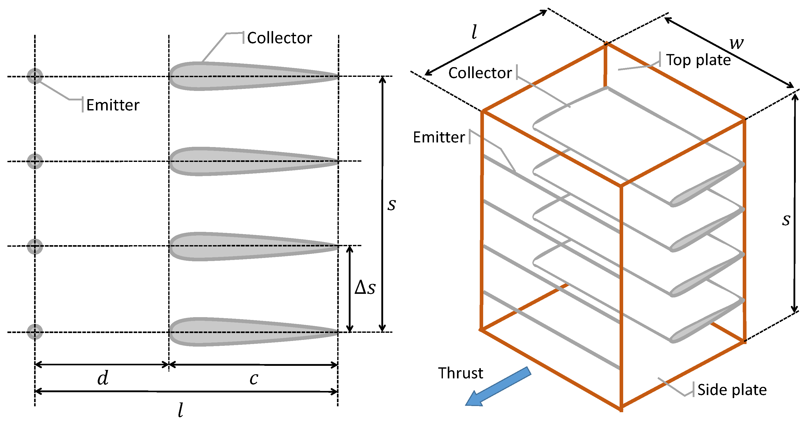
To the aim of setting up a computational procedure able to manipulate the variables that assign the geometry of the thruster according to an automated algorithm, the definitions in Figure 2 should be assumed. Considering a single emitter-collector couple in that figure, c is the chord of the collector, and d is the distance between the emitter and the leading edge of the collector. The sum of these distances gives l = c + d . Considering a cluster of more emitters and collectors forming a thruster, the distance between two adjoining collectors is defined as Δ s , whereas the total radial extension of the thruster is s, and it can be obtained from the number of collectors N c and the distance Δ s as s = N c Δ s .
The length l and height s define two components of the overall dimensions of the thruster. The last one, namely a measure of width w, is bound to the span of the collector. Due to the physics underlying the plasma-based propulsive effect, it is typical to have a minimum size constraint, which comes in terms of minimum gap d min between the emitters and collectors, a minimum span w min to reduce boundary effects close to the tips of the collectors, as well as minimum radial and longitudinal extensions (respectively s min and l min ) of the overall thruster.
The supporting structure of the thruster is composed of two side plates and load-bearing rods connecting them. Thanks to the generally low values of forces involved, a light material can be employed for the supporting structure.
The thruster is electrically fed, with voltage employed for regulating the intensity of thrust. The manipulation of electrical variables requires the employment of specific electric components, including a voltage booster. Typically employed out of the aeronautical domain, existing realizations of this component feature limited weight performance, expressed through a high value of the weight-to-power ratio. However, novel and more performing exemplars of this technology are under development within project IPROP to allow for easier adoption of this component on flying machines.
In terms of performance, similarly to the domain of turbomachinery, it is typical to define as characteristic figures of the proposed atmospheric ionic thruster structure a thrust-over-frontal area ratio T A m , thrust-over-weight T W m and thrust-over-volume T V m . Furthermore, a power efficiency measure can be defined through the parameter T P m , where P m is the power flow required from the electrical system to produce the corresponding thrust. From experiments, preliminary figures have been obtained for all these quantities within project IPROP, according to the general layout of the proposed specific implementation of the thrusters.
The material arrangement of atmospheric ionic thrusters on airships is currently a matter of investigation [23]. Different promising solutions are currently under investigation, up to now set up mostly considering the advantages and shortcomings of the mutual placement of multiple thrusters in a streamwise direction on the side of the envelope. The interaction of multiple streamwise aligned thrusters—which, in that configuration, take the name of longitudinal stages—is still under investigation [24,25], and results currently available appear to indicate the existence of constraints on the minimum longitudinal distance between the stages and a maximum recommendable number. This is explained by a significant increase in drag, besides thrust, associated with an increase in the number of stages. This, in turn, produces a progressively less steep increase of the net thrust per additional stage when the number of longitudinal stages is increased.
An option considered in the present study is that of arranging multiple thrusters sharing the frontal area, but set sufficiently apart in a longitudinal direction to allow considering the interaction between streamwise aligned thrusters negligible. Where the study of the detailed lofting of multiple thrusters on board the airship has not been included in the present work, the adoption of this layout allows some flexibility in the longitudinal placement of the thrusters, which is of great relevance for longitudinal balancing in static or near-hover conditions [7,9], as well as for maneuverability. These static balance (i.e., trimmability) and dynamic performance aspects (including both the configuration of the eigenmodes of the free response, bound to the inertia of the system, and controllability, bound to the positioning of thrust forces in the configuration), which of course constrain the positioning of thrusters, as well as that of stages in a streamwise close-coupled multi-stage arrangement, will be in the focus of further studies within IPROP.

3.2. A Sizing Methodology for Atmospheric Ionic Thrusters on Airships

From the standpoint of a sizing algorithm, the adoption of atmospheric ionic thrusters requires the definition of a series of geometrical and technological parameters while leaving one (or a set) of design parameters free to tune so as to cope with design requirements. The actual sizing value of this parameter (or this set of parameters) shall be defined based on the same type of requirement leading to the adoption of a certain electric motor in the baseline procedure (Section 2), namely the need to satisfy equilibrium conditions along the mission profile.
A difference between the sizing of atmospheric ionic thrusters and electric motor/propeller assemblies may lie in the fact that the former, where scaled up in size to increase thrust, may tend to concurrently increase drag, mostly due to the side plates and thruster cover (the latter has been assumed in the current implementation, but it is not necessarily always present), forming a nacelle for the thrusters, similar to ducted fans or jet engines on aircraft. Such an increase in drag needs to be assessed so as to avoid over-estimating the advantage on the net thrust of increasing the size of the thrusters.
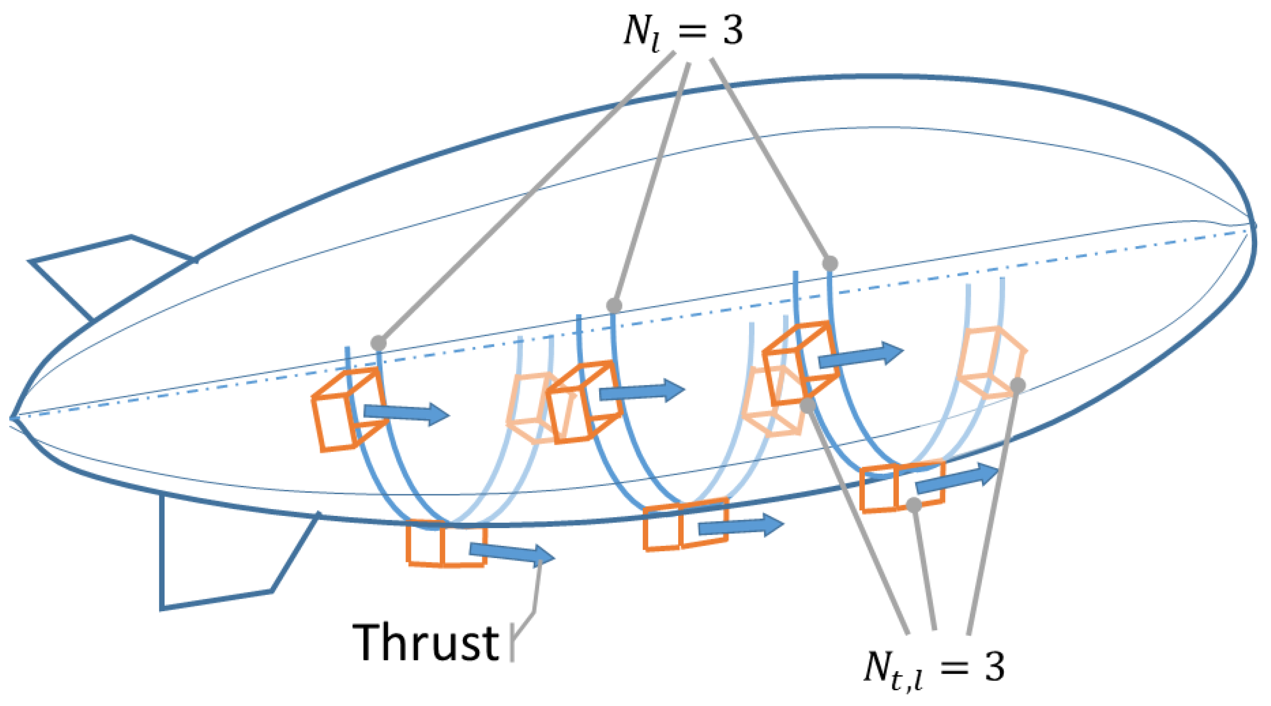
According to the topology presented in Figure 3, considered in the present work, it is assumed that the thrusters are placed on the lower half of the airship for obvious balance reasons (center of buoyancy above the center of gravity). Their number at a certain longitudinal section, N t , l , combined with the number of longitudinal stations N l , is such that the total number of thrusters is N t = N l N t , l .
Of course, the actual specific positioning of the thrusters on board will have an impact on free dynamics (through the corresponding positioning of the center of gravity and the values of the components of the inertia tensor) and the controlled response of the airship. However, this level of detail will be dealt with through an analysis of lofting (further on within project IPROP), which is triggered by the preliminary sizing presented in this work.
In the proposed sizing methodology, the amendment due to the adoption of atmospheric ionic thrusters is included at the level of the estimation of the thrust required for the mission profile (Section 2.1), as will be detailed in the following paragraphs.

3.2.1. Assigned Geometrical and Technological Parameters

First, it is assumed to work with assigned data concerning the following aspects.
  • Geometrical features of each thruster. In particular, referring to Figure 2, quantities l, w, and s are assigned (they are optimized in the laboratory, starting from basic theoretical models, currently being employed at Politecnico di Milano in conjunction with practical testing). This yields an a priori knowledge of the geometrical sizing of each thruster unit. In particular, it is assumed for simplicity that s = w implying a square front section of each thruster.
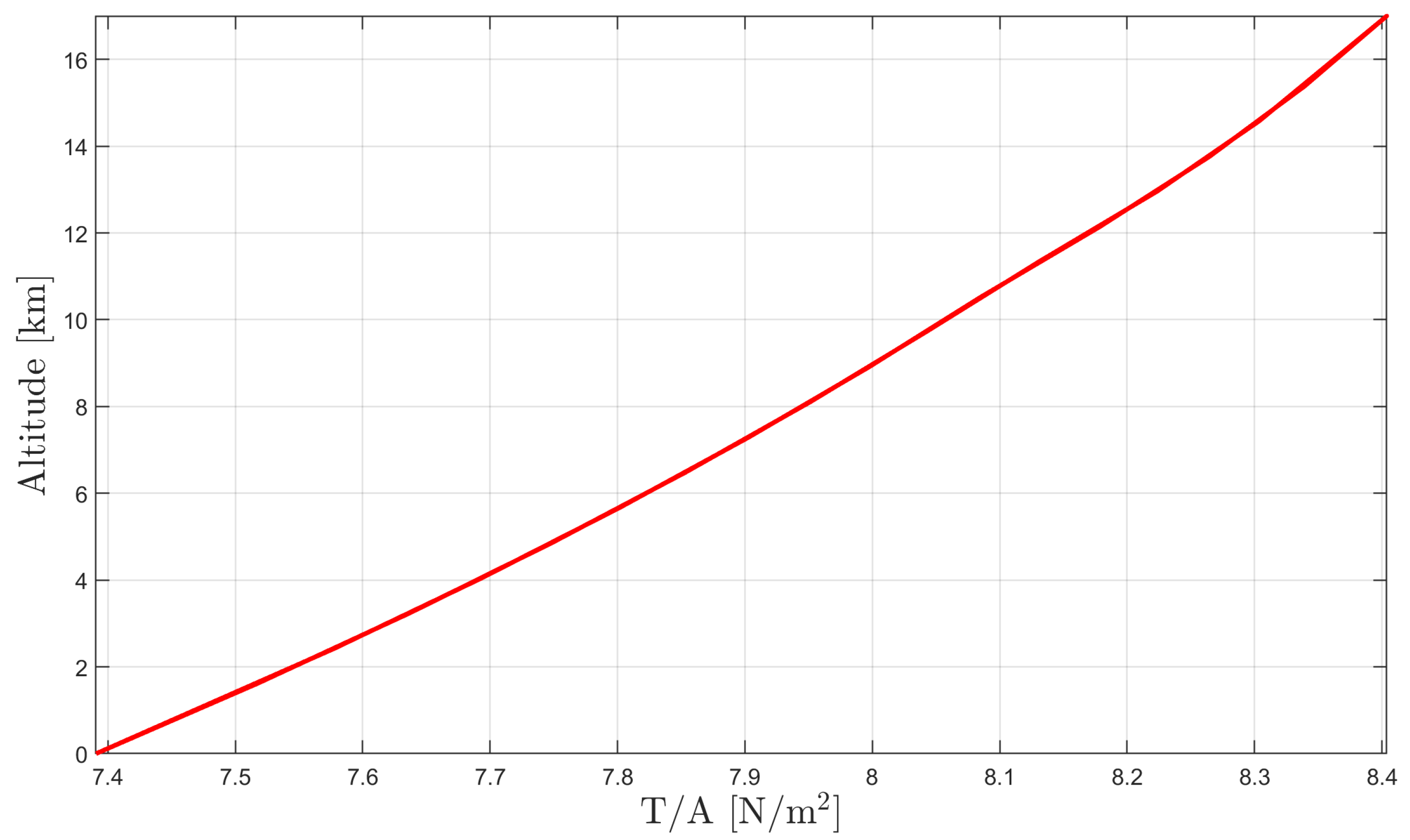
  • Thrust-to-frontal area. The value of the ratio T A m follows an assigned behavior with the altitude (similar to geometrical characteristics of the thruster, experimentation on the optimization of this value through a selection of the thruster configuration, supported by a dedicated theoretical model, is well underway within project IPROP). This relevant assumption is supported by the adoption of a certain geometry and general arrangement of the components within the thrusters (e.g., the relative numbers and positioning of emitters and collectors, the sizing of the basic components like c, d and Δ s , etc.). This behavior shows an increasing trend, yielding an increasing value of the ratio with the altitude [24,36], according to the law displayed in Figure 4. It can be observed that the T A m ratio is generally increasing with the altitude.
  • Thrust-to-power. The ratio T P m is a measure of the efficiency of the thruster, and it might bear an impact on the actual value of power required from the electrical system (and batteries in particular). The behavior of this quantity with altitude is currently a matter of investigation (among the aims of project IPROP). For the present work, assumptions on the behavior of the thermodynamic state of the atmosphere at altitude, known to bear an impact on the T P m ratio, have been employed to feed a preliminary first-principle model [24,36], thus producing the behavior in Figure 5.
    From the figure, it is immediate to check that T P m is decreasing with the altitude, yielding a less efficient conversion of the power fed to the thrusters into thrust when the airship approaches higher layers of the atmosphere.
  • Arrangement and number of thrusters. Based on the assumed size of the frontal area, in particular, considering the width w, it is possible to compute the maximum number of thrusters N t , l to put on a longitudinal station of the airship hull by simply considering the bottom half-circumference of that station and dividing it by the width of each thruster. However, it is interesting to study the effect of the placement of the thrusters, also considering reducing the top number of units that can be arranged on a longitudinal station (a dedicated paragraph is correspondingly included in the application section). To this aim, we introduce a blockage parameter ξ , considered to be assigned and constant and representing the share of the bottom half-circumference of a longitudinal station that can be taken over by the thrusters. When ξ = 1, the entire bottom half-circumference is available for the thrusters. Conversely, when (for example) ξ = 0.5, only half of the bottom half-circumference is available for placing thrusters, and correspondingly, gaps will appear between thrusters on the same longitudinal station.
  • Voltage booster. The voltage booster is associated with a technological figure, namely a ratio of the power over weight and to a voltage level. These quantities are considered to be assigned and constant.
It should be remarked that the assignment of these parameters corresponds to the definition of a certain structure of the thrusters and a corresponding characterization of their performance. These choices clearly influence the results. Given the relative immaturity of the atmospheric ionic thruster technology, since many of these quantities have been estimated through experiments in laboratories and not always from measurements in a relevant environment for high-altitude employment, the results presented in the application section take the meaning of a preliminary feasibility assessment (as cited in the title of this work). However, the employment of provisional figures of performance within the sizing procedure allows the illustration of its potential and draws some interesting preliminary results as well.

3.2.2. Amendments to the Baseline Sizing Procedure

As can be argued from the listing of parameters just introduced, the geometry of a single thruster is considered to be assigned completely, and its technological characterization is similarly available. Conversely, the number of thrusters to be put on board has not been assigned, in particular since the number of longitudinal stations N l is unknown, and the number of thrusters N t , l on a given longitudinal section is a function of the circumference of the cross-section of the airship.
Within the sizing loop proposed for airship sizing in the baseline scenario (Section 2.1), it is possible to carry out the computation of these additional parameters in a way that satisfies equilibrium along the mission profile.
This is conceptually similar to the baseline case, where thrust is obtained from an electric motor/propeller assembly. However, a significant difference with respect to the baseline case is in the relationship between the thruster size (hence its nominal thrust) and drag. Actually, at the level of the computation of the drag coefficient C D , 0 , an additional component due to the presence of the nacelles of the thrusters must be taken into account. To this aim, an inner iterative loop where the value of N l is solved has been envisaged as follows. The starting point is a first-guess sizing, where the number of longitudinal stations N l is considered N l = 1, and, consequently, the number of thrusters is N t = N t , l . Starting from this first-guess candidate solution, the following amendments to the original sizing procedure (Section 2.1) are included.
  • Compute the drag coefficient C D , 0 associated with the configuration of the thrusters. This can be performed starting from the drag coefficient value obtained for the airship without thrusters and estimating the additional contribution due to the nacelles of the thrusters. This step can be performed based on a model of the nacelle sides as flat plates. The drag coefficient of the plate is obtained as a function of the relative velocity and viscosity of air and of the length of the plate, which compose the Reynolds number. Then, the drag coefficient obtained for one nacelle can be multiplied by N t to obtain the total additional drag Δ C D , 0 , hence the actual value of C D , 0 .
  • Compute the drag for each node along the mission profile. From this time series of values, the maximum drag encountered over the mission as D t o t , max can be computed.
  • Compute the nominal available thrust. Based on the number of thrusters on board N t , assumed in the current run of the sizing loop, and based on the value of the thrust-to-area ratio T A m , it is possible to compute the actual value of thrust at the altitude corresponding to each time node along the mission, multiplying the total front area of all thrusters A m = w s N t by that ratio, thus yielding
    T = T A m w s N t .
  • Check the minimum difference of the thrust available vs. drag. Following the computation of the thrust available at every altitude and, correspondingly, the drag, it is possible to check whether the installed thrust is sufficient to compensate for the drag, especially in the worst conditions encountered along the profile. In analytic terms, that check corresponds to the evaluation of the constraint
    ( T D ) t o t , min > 0 .
    In case the constraint in Equation (8) is not satisfied, thrusters are added on a further longitudinal station, increasing the number N l by 1 and restarting from point 1. of this cycle, with a new total number of thrusters N t = N l N t , l . Conversely, if the inequality in Equation (8) is satisfied, the procedure is over.
Upon reaching convergence, the number of the thrusters will be such that their thrust will be able to balance the requirement of the mission even in the worst condition, accounting for the drag penalty due to the nacelles. With this inner sizing constraint satisfied, it is possible to size the batteries according to point 4. in Section 2.1 and Equation (1) in it (with the only caveat that the propeller efficiency η p and electric motor efficiency η m need to be taken out of the expression). The sizing loop then proceeds along points 5–7. in Section 2.1.
As a remark, it should be noted that the drag associated with the stream flowing within the thrusters has not been accounted for explicitly. This is due to the fact that the T A m figure specified for a certain atmospheric ionic thruster construction represents a net thrust. This is in accordance with what is typically done to provide the characteristic performance of any thruster (e.g., the thrust figure typically specified for a jet engine is not such that the drag of the flow blowing through the compressor and turbine vanes needs to be taken away from it in order to obtain the actual thrust).
Once the inner sizing loop producing the geometry and thrust of the propulsive system has been assigned, the corresponding mass can be assessed in order to amend the computation of the weight breakdown within an optimal design procedure, as presented in Section 2.1. The weight components associated with the atmospheric ionic thruster can be listed as follows:
  • Wires employed as emitters. Due to their very limited diameter, these components are associated with a negligible weight.
  • Collectors. Depending on the material employed and structural sizing (i.e., hollow or filled structure), the weight may vary significantly.
  • Load-bearing structure. Thanks to the relatively low value of force exerted by each thruster, its load-bearing structure can be manufactured with relatively light and flexible material. The cage structure naturally resulting from the setup of this type of thruster allows the obtaining of overall good levels of rigidity at the price of a mild global weight of the structure.
  • Nacelle. The material of the nacelle may be the same as the load-bearing structure. The sides of the nacelle may be actually part of it. The structural role of the nacelle top is typically not relevant; hence, this component can be manufactured from very light material.
  • Voltage booster. As pointed out, this component is typically not to be found in powerplants for aviation, and its corresponding weight-to-power figure may be somewhat penalizing, albeit already compatible with airship flight operations at the current level of technology. Ways to obtain a better value of this parameter are currently under study (within project IPROP).
The weight corresponding to atmospheric ionic thrusters can be related to their thrust through a thrust-to-weight parameter T W m , which accounts for the aggregated contribution of all the components in the previous listing, except the voltage booster. This allows the definition of the weight of the propulsive units W m from the knowledge of the top thrust, whereas the weight W v b of the voltage booster is typically computed separately, based on the power it has to deal with, which in turns is again related to the top thrust to be obtained from each thruster.
The weight breakdown in Equation (2) can be, therefore, built up according to a modified set of components, as
W = W e n v + W l g + W b a l + W s c + W b a t + W m + W e l + W v b + W g o n + W s t r + W t + W p l ,
wherein it should be observed that the weight of the gondola W g o n can be obtained as a function of the weight of the voltage booster W v b , as well as of the other components stored in the gondola according to the adopted baseline architecture.
The optimal problem introduced in Equation (6) remains unchanged. The addition of a further parameter (namely N l ) to be solved by the sizing algorithm does not alter the set of optimization parameters p . From a mathematical-numerical perspective, such an additional variable is not continuous and cannot be managed directly by a gradient-based algorithm working on continuous variables (listed in p ). For this reason, this quantity needs to be treated via the inner loop just introduced, nested inside the algorithm, leading to the evaluation of the merit function W. A value of N l can be obtained for each assigned set of parameters in p encountered along the numerical solution of the optimal problem.
It is relevant to remark that the solution obtained from the sizing procedure just outlined is totally dependent on the many assumptions on the geometrical and technological features of the thruster (as pointed out in Section 3.2.1). For this reason, an evaluation of the sensitivity of the outcome of the design procedure with respect to these parameters is of great interest, and it will be assessed in the application Section 4.

4. Application Studies

As pointed out in the introduction (Section 1), it is interesting to show the result of the application of the comprehensive sizing procedure described in this work. It has been explained in Section 3.2 how the original sizing algorithm recalled in Section 2, intended for airships featuring standard electro-mechanical propulsion, and practically wrapped in the suite Morning Star (which works in Matlab® R2019b), can be enriched with features so as to allow the sizing of an airship accounting for the specific features of atmospheric ionic thrusters. As an example application, considering the goals of the project IPROP, a high-altitude airship mission has been considered, with a realistic payload and mission profile, which will be introduced next. A comparative study is presented then, where an airship featuring standard electro-mechanical propulsion is sized to be able to fly that mission concurrently with another airship featuring atmospheric ionic thrusters. The outcome of this first analysis allows the comparison of the effect of the inclusion of atmospheric ionic thrusters in the design of airships with a high-altitude mission. The so-obtained design of a machine based on atmospheric ionic thrusters is then employed as a baseline for further analyses of the outcome of optimal sizing obtained for changing values of some parameters related to the mission profile or the technology of the components.

4.1. Baseline Mission Characteristics and Payload

In the following, the results of optimal sizing will be presented referring to a baseline high-altitude station-keeping observation mission, where the airship takes off, climbs to a cruising altitude h c r = 17 km (chosen according to the payload requirements and an a posteriori justification, shown later in this section), and keeps there for an active observation phase of the mission. It then descends back to the original take-off level. The entire mission duration is T = 48 h. This duration, which involves two daily recharge-discharge cycles besides the climb and descent phases, is well representative of a longer (virtually permanent) multi-day flight mission. All along the mission profile (including ascent and descent phases, and of course, the station-keeping phase at altitude), the airship faces realistic characteristics of the environment, and in particular, changing values with respect to the altitude of the atmospheric thermodynamic state, including temperature, pressure, and density, as well as of the horizontal wind and solar radiation (both in intensity and direction). As pointed out in the methodological section (Section 2.1), in order to simplify the analysis, thus focusing on aspects of more direct interest considering this example application, a representative profile for all cited quantities has been elaborated, averaging samples from locations at different geographical locations over an entire yearly cycle, obtained from state-of-the-art models (in particular, those described in [31,33,34]), so as to create a realistic reference profile with altitude, uncorrelated from any specific position or time of the mission.
The basic data defining the desired mission profile are reported in Table 1. It should be noted that for a station-keeping mission, the ground speed on the cruise is null, and the airspeed in that condition is dictated by the velocity of the wind at cruising altitude. The latter is, therefore, not a specification by the designer.
The payload for the mission has been designed so as to obtain state-of-the-art detection capabilities in the visual and infrared spectra, as well as a radar scanning ability through a synthetic aperture radar (SAR), thus yielding a monitoring capability of the ground from altitude through the weather. The selection of detection systems is reported in Table 2. This payload capability configures a complete airborne detection platform, merging the abilities of different existing flying systems in the same machine. The resulting weight of the payload reaches W p l = 576 kg, adsorbing a nominal power P p l = 14.85 kW.

4.2. Comparison of Design Solutions on Baseline Mission

The technology of onboard systems and components has been chosen to be as standard as possible so as to avoid unrealistic projections in the characteristics of the out-coming design. Furthermore, both the conventional airship based on electro-mechanical thrusters and the one based on atmospheric ionic thrusters share most of the choices concerning components, including, in particular, key contributors to the weight breakdown like the envelope and batteries. The data employed for the envelope material, battery, and electrical wiring in both designs are reported in Table 3.
Concerning the envelope material, data in Table 3 refer to a laminated material, based on a sandwich composed of Zylon® (Madrid, Spain) fibers in the middle as a load-bearing component, a Mylar® (PET) film (Chester, VA, USA) for an internal gas barrier layer, a Kapton® (PI) film (Tianjin, China) with an aluminum deposit and Corrosion Resistant Coating (CRC) as top weathering layer, and two EVOH films as adhesive layers between other functional layers [37]. Battery technology data refer to off-the-shelf products based on Lithium-Polymer chemistry. Electric cables are manufactured from standard copper wires.
Considering the airship based on standard electro-mechanical propulsion, this employs electric motors and propellers to propel the airship. In this case, the sizing of the propulsion system requires the definition of a technological relationship between the power needed for propulsion and the weight of the motor so as to define W m in Equation (2) based on the value of required power P r , max resulting from the mission. In particular, a linear relationship based on motors for industrial applications of comparable power as for the airship at hand has been employed, yielding P r , max g W m = 1905 kW/kg. Furthermore, as required according to Equation (1), values of the propeller and motor efficiency, respectively, of η P = 85% and η m = 95% have been assumed [38].
For the solution based on atmospheric ionic thrusters, the definition of a feasible solution requires not just the definition of the installed thrust (as for the electro-mechanical case), but conversely, it comes together with the definition of a general arrangement and the number of thrusters on board. As explained (Section 3.2.2), the reason for that is the dependence of both propulsion and drag on the number and sizing of the thrusters for this technology. As parameters for the sizing, a square frontal area has been hypothesized for each thruster, yielding a height of the thruster of s = w = 2 m. The length in the streamwise direction is l = 0.055 m, dictated by the arrangement and sizing of emitters and collectors currently under study within IPROP. The number of emitters and collectors within a thruster has been set to 80. It should be noted that these figures are very preliminary since atmospheric ionic thrusters are currently being developed primarily for smaller-scale applications [28]. The density of the collectors within the atmospheric ionic thrusters has been assumed at 50 kg/m3, corresponding to a styrofoam-based structure coated in light metal alloy, from experiments on prototypes developed within the activities of project IPROP. A 50% infill allows the actual reduction of this figure by the same amount without apparently producing any detrimental effect on structural stiffness. The density of the external structure of the thruster is assumed of 50 kg/m3, similar to that of the collectors. It has been practically checked that a load-bearing structure made of this material, where suitably lofted, allows the supporting of the range of loads to which the thruster should be subjected. The blockage parameter ξ , defining the share of the bottom half-circumference of a cross-section of the airship available for putting the thrusters (see Section 3.2.1), has been set to ξ = 1.
The thrust-to-area ratio T A m and thrust-to-power ratio T P m have been assigned as functions of the altitude, as shown in Figure 4 and Figure 5, respectively. Finally, a currently achievable value of W v b P m = 0.83 kg/kW has been assumed for the voltage booster.
The outcome of the weight-optimal sizing for both concurrent designs is reported in Table 4. Concerning the constraints in the optimal sizing, for both designs, the value of the buoyancy ratio has been set to B R = 0.93, the nominal stress limit has been set to σ ¯ max = 970 N/cm, and the specific energy of the battery to 450 J/kg.
The number of thrusters, defined only for the case of atmospheric ionic thrusters, is N l = 30 and N t , l = 41, yielding a total of N t = 1230 thrusters.
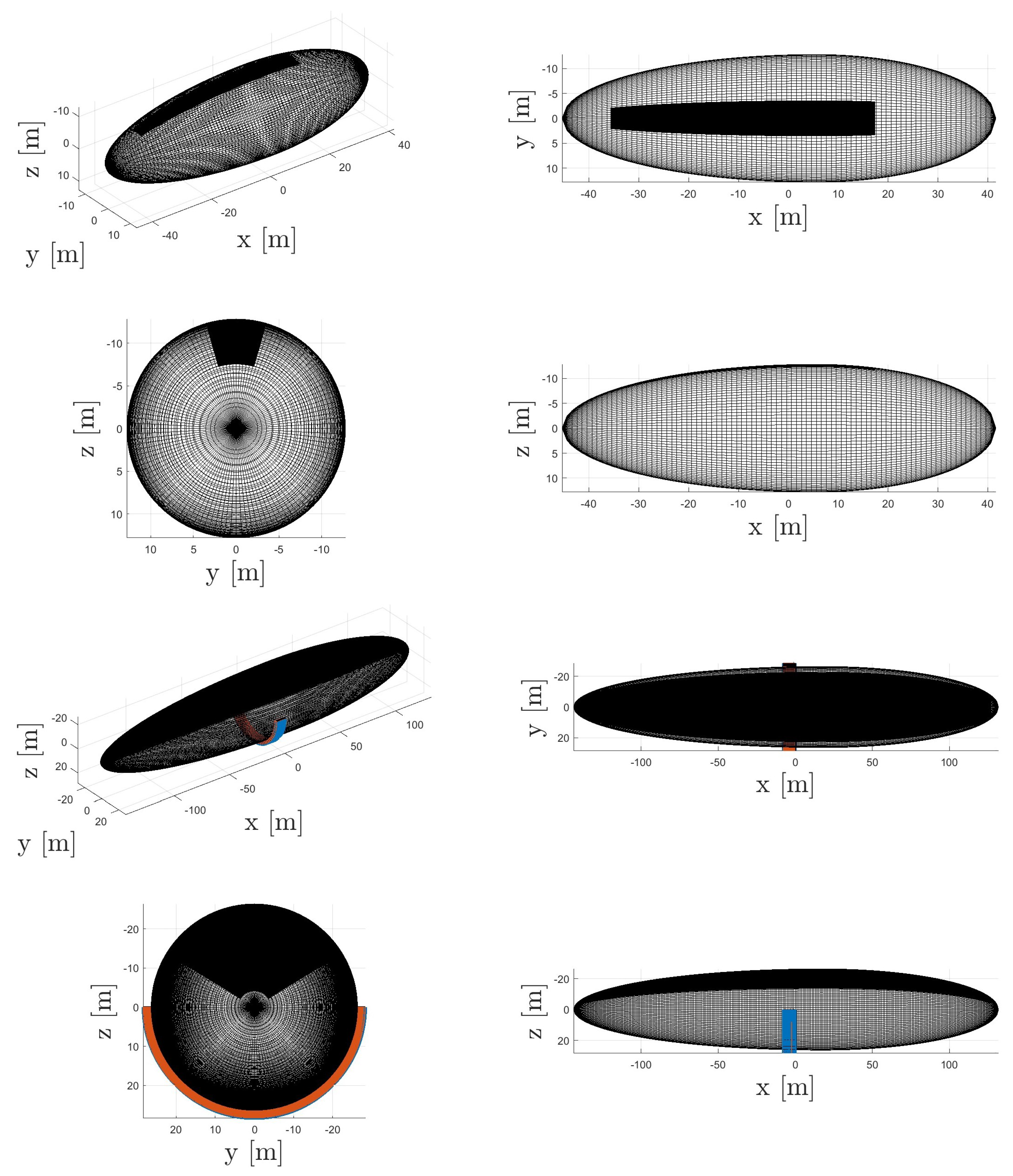
To help appreciate the features of the respective design solutions, the corresponding geometrical sizing has been reported in Figure 6. In these figures, it is possible to check the actual shape and geometrical sizing of the envelope, the extension and positioning of the solar cells, and, for the atmospheric ionic solution, the sizing of the thrusters. For the latter, the longitudinal positioning in the sketch is the result of an arbitrary assumption. As pointed out, future research will be devoted to the actual optimal placement of the thrusters on board in view of the obtainment of a desired dynamic performance.
From Table 4, it can be noticed that both airship designs correspond to a significant geometrical size. To allow for a direct visual comparison, despite very limited scientific validity due to the completely different missions for which the respective ships have been sized, it can be observed that the conventional airship compares well in size with the Zeppelin NT, whereas the one pushed by atmospheric ionic thrusters with the Zeppelin LZ129. According to the same comparison, the weight of the conventional design is less than one half that of the Zeppelin NT, with which it shares the general non-rigid construction, and similarly, the weight of the design based on atmospheric ionic thrusters is less than one half that of the Zeppelin LZ129, which however featured a radically different rigid structure. The relatively contained overall weight figures for the designs presented here are a result of the comparatively low payload compared to the transport airships just cited.
The fineness ratio of the ion-based design is higher, yielding a significantly slenderer shape compared to the standard propulsion case. The weight breakdown for the two designs at hand features some relevant differences, which can be linked to the constitutionally lower weight efficiency of the novel thrust generation system, which includes, for instance, a voltage-boosting component creating a weight offset with respect to the conventional design. A corresponding increase in the lifting volume, hence in the weight of the envelope and lifting gas, is obtained. This, in turn, corresponds to an increase in size, which pushes the energy balance towards higher values of drag and thrust, which tend to increase the requirement for energy harvesting and storage systems. Despite these differences, both designs appear feasible, with the novel one based on ion technology bringing in the strategic advantages mentioned in the introduction (Section 1), which include very low detectability and a higher TBO.
As a remark, it should be recalled that the results presented in this work have been obtained willingly as a preliminary forecast based on the current level of technology, i.e., without accounting for any assumption on the yield of future developments. The so-obtained preliminary results are, therefore, especially encouraging, showing that even with the strict assumptions just mentioned, a stratospheric design based on atmospheric ionic thrusters is theoretically feasible. Clearly, since project IPROP is largely dedicated to the increase in the technological readiness of atmospheric ionic thrusters and all related components (including the voltage booster), it is very likely that the figures just presented will be improved further, as the research in this field unfolds.

4.3. Effect of Mission and Technology Parameters on the Design Solution

The design solution obtained from the optimal sizing procedure in Section 4.2 shows that a significant difference exists between an airship sized considering conventional thrusters and that obtained from atmospheric ionic thrusters. As anticipated, it is interesting to investigate the sensitivity of the design solution obtained when the novel atmospheric ionic thrusters are mounted on board, and corresponding to changing values of some parameters either pertaining to the mission or bound to technological assumptions.

4.3.1. Effect of Stationing Altitude on the Design Based on Conventional and Atmospheric Ionic Thrusters

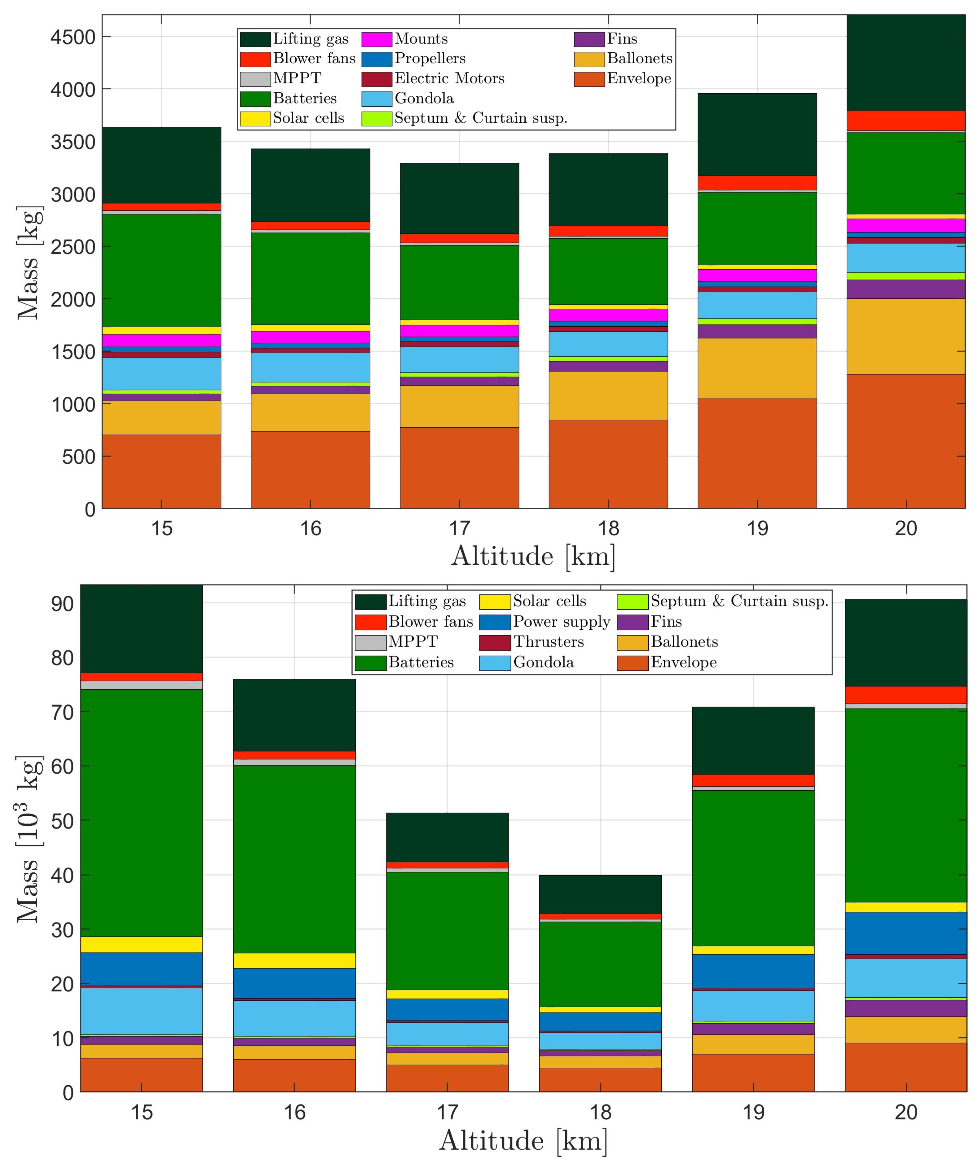
Considering the high-altitude mission of interest here, a relevant quantity to consider as a changing parameter is the target altitude for the stationing phase. In Figure 7, the change in the weight breakdown corresponding to weight-optimal solutions at different target altitude values is presented for the conventionally propelled airship (top plot) and the airship based on atmospheric ionic thrusters (bottom plot).
Looking at the results for the conventionally propelled airship (top plot in Figure 7), the choice of the reference altitude for the baseline design at h c r = 17 km can be reinforced a posteriori. As already pointed out, such an altitude value is ideal for the selected payload. Additionally, from the plot, it appears to correspond to a typical sweet spot for the overall weight of the machine. It should be underlined that the very existence of a condition of minimal weight is interesting in itself.
Considering the optimal altitude of h c r = 17 km, the trade-off resulting in the behavior of the weight breakdown portrayed in the plot can be explained according to at least four drivers. A lower level of radiation intensity and a more intense wind are encountered at a lower altitude, corresponding, respectively, to a higher weight of the batteries (which need to store more of the energy required for the mission) and installed thrust (needed to overcome a more intense drag). On the other hand, at higher altitudes, an increase of the ballonet sizing and a higher volume of lifting are observed, due, respectively, to the need for producing a buoyancy force with a lower density of external air and to the (non-linear) decrease in the pressure of air as more altitude is gained. The balance of all these antagonist effects bears the trend resulting in the plot of Figure 7.
From the bottom plot in Figure 7, the novel design based on atmospheric ionic thrusters appears to follow a more complex trend. In particular, it can be observed that the global weight minimum is obtained for an altitude of h c r = 18 km, which is different from that corresponding to the conventional propulsion case, and the increase trend of weight for a changing altitude is generally steeper than for the other case. Furthermore, the weight of the ballonet system is not monotonically increasing, in contrast with the previous case. To help explain these differences, it should be recalled that the optimal sizing algorithm accounting for atmospheric ionic thrusters computes the actual number of thrusters (this is not true for the conventional case, where only the overall installed power is computed), choosing it so as to simultaneously guarantee a sufficient propulsive power and produce a minimal-weight solution. However, the thrust required (due to drag) is also a function of the number of thrusters, as pointed out. This feature in the design procedure reflects an additional complexity in the sizing of the airship in the presence of atmospheric ionic thrusters, i.e., the inner link between the sizing of the thrusters and drag, besides the more obvious relation with thrust. The number of thrusters corresponding to the optimal solutions at increasing altitude presented on the bottom plot in Figure 7 is reported in Table 5.
The total number of thrusters N t for each sizing solution in Table 5 is obtained by multiplying N l and N t , l . Cross-checking Table 5 together with the right plot in Figure 7 allows the discovery of a correlation between the number of thrusters and the overall weight, which offers an interpretation of the trend just observed. As an additional driver yielding that trend, it should be pointed out that in the case of atmospheric ionic thrusters, the thrust produced by these thrusters increases with the altitude, through an increase in T A m , whereas the value of the thrust-to-power ratio T P m decreases, as mentioned in Section 3.2.1. This further trade-off contributes to producing an offset of the optimal altitude for this case, compared to the conventional propulsion case, and also supports the very existence of an optimum.

4.3.2. Effect of Envelope Density on the Design Based on Atmospheric Ionic Thrusters

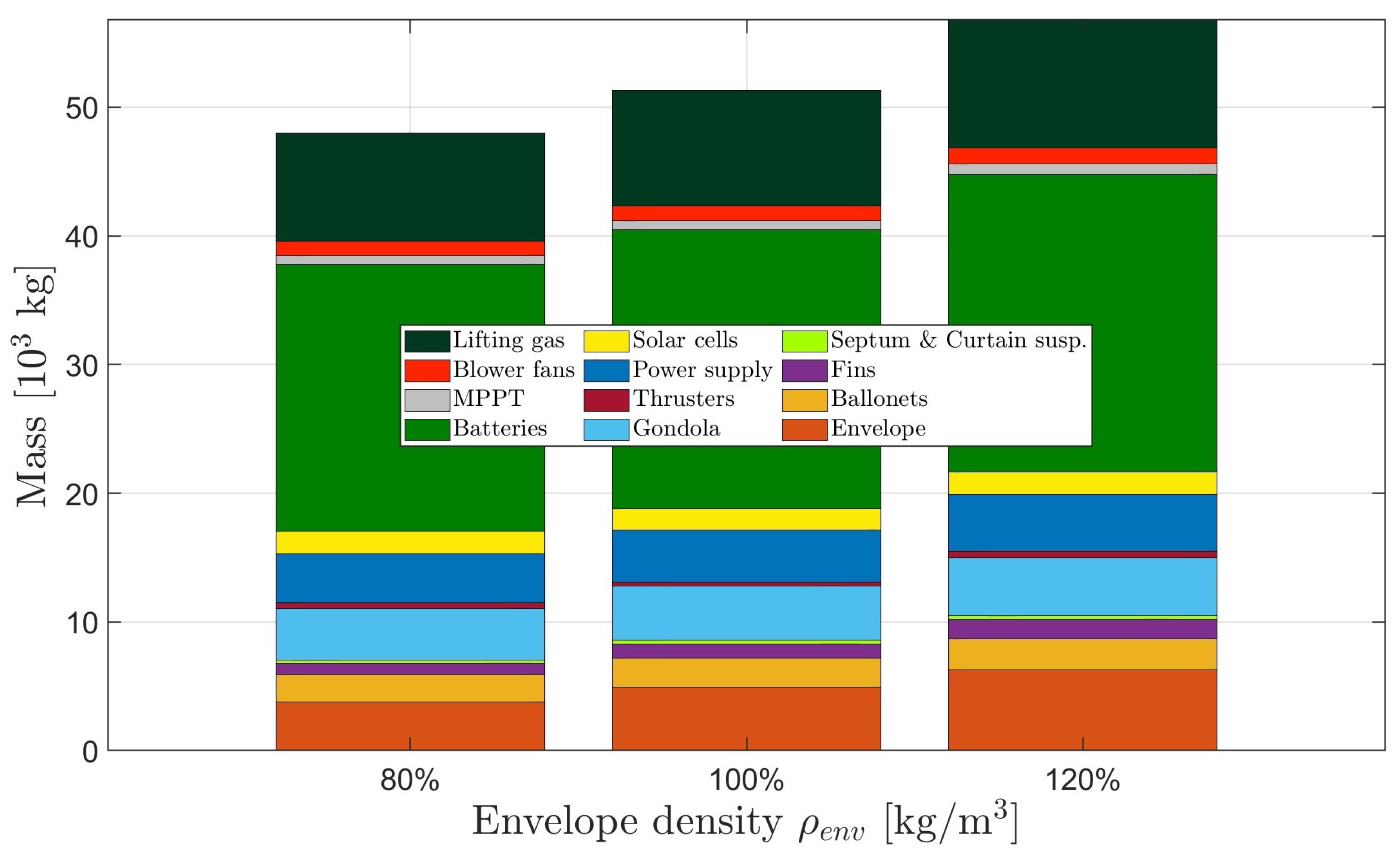
Considering the significant share taken by the envelope in the baseline design (see Section 4.2) and the level of innovation required for the manufacture of the airship envelope for a mission in the higher layers of the atmosphere (due to the mechanical stress bound to the wind, and to the extreme intensity of the solar radiation), a second interesting parameter is the density of the envelope. The plot in Figure 8 reports the result of the weight-optimal sizing of an airship featuring atmospheric ionic thrusters for two additional values of the envelope density, respectively, 80% and 120% of the baseline value.
The trend appears regular in all these cases for all weight components in the breakdown, corresponding to the fact that the number of optimal motors remains unchanged. An upscaling effect especially on the batteries and lifting gas (corresponding to an increase in size, not portrayed), and of course on the envelope, is found for increasing values of the envelope density. Furthermore, it can be noticed that the trend of the output total weight is considerably steep, showing a significant change in weight for the considered (relatively small) change in the density. Also a slightly non-linear increase can be noticed, with a weight penalty when increasing the envelope density from the baseline bigger than the weight saving when decreasing the density by the same percent amount.
These results show, on the one hand, that the effect of the density of the envelope is, as expected, sizeable. However, at least for the considered changes in this parameter, the outcome is not different to the point of altering the general geometric sizing of the airship (as can be seen from the lifting gas, which is proportional to volume), which remains in the size class of the baseline.

4.3.3. Effect of the Sizing of Atmospheric Ionic Thrusters

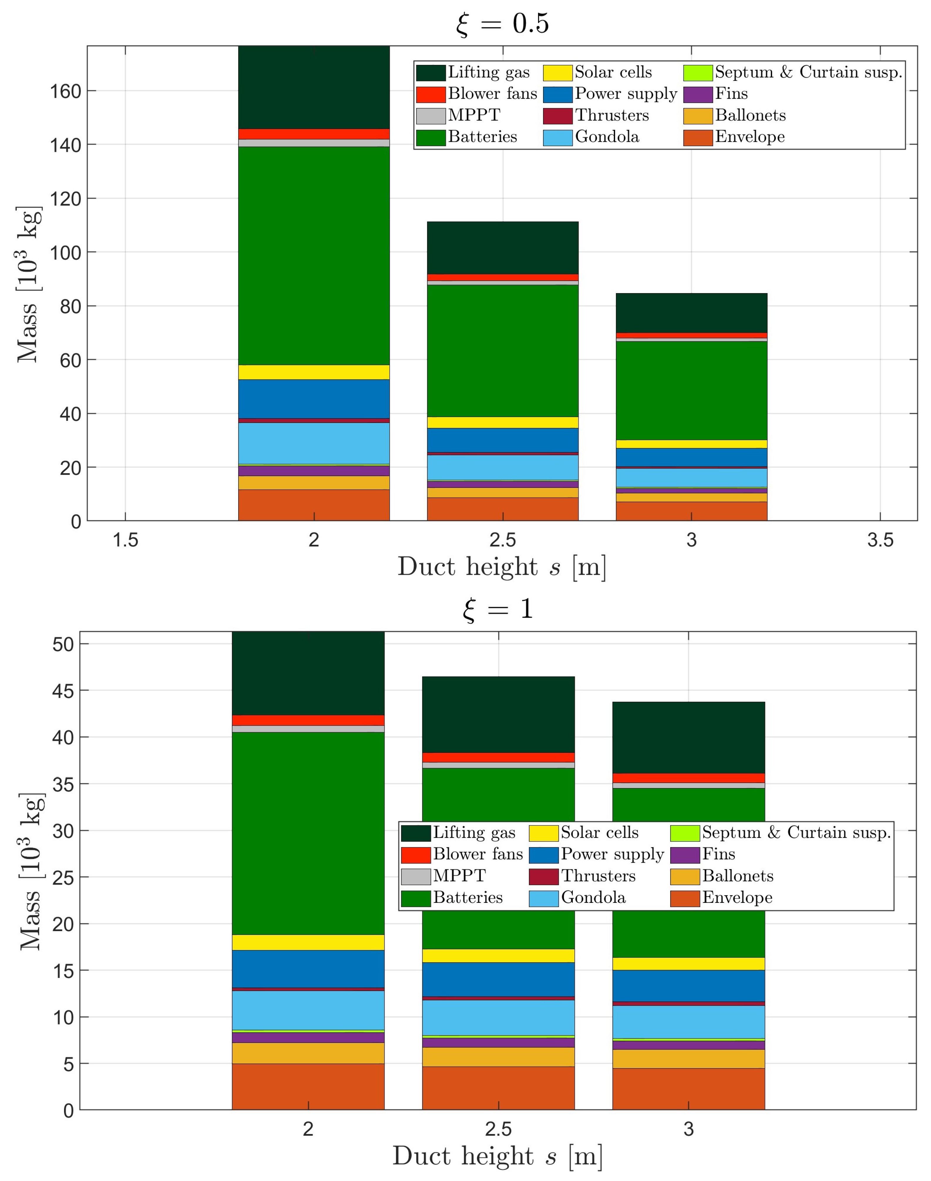
Considering the focus put in this paper on the development of a reliable technique capable of sizing an airship pushed by atmospheric ionic thrusters, it is interesting to show how this procedure can cope with two key parameters concerning the general sizing and arrangement of atmospheric ionic thrusters. In particular, it is hypothesized to change two parameters. The first is the maximum affordable blockage of the front section, already introduced as a non-dimensional parameter ξ ranging between 0 (extreme value, non-physical) and 1. Considering Figure 3, a value of ξ = 1 implies that the entire half-circle corresponding to the bottom half of a cross-section circumference of the airship can be taken over by the thrusters. A lower value of this parameter reduces the occupation of the frontal area, thus reducing the blockage of the front section of the airship due to the thrusters. Setting this parameter restricts the maximum number of thrusters per section, i.e., N t , l , to an extent that depends also on their geometrical sizing and the actual sizing of the airship envelope. Correspondingly, as a second parameter, the height s and width w of the front section of the thruster are increased while retaining a square shape (thus, they are treated as a single parameter, given that s = w , as observed).
The results obtained combining the changes in these parameters are reported in Figure 9. A blockage parameter of ξ = 0.5 or 1 is considered, respectively, for the top and bottom plots. In each plot, the value of the width and height of the thruster section is increased as reported.
The corresponding number of thrusters is reported in Table 6.
Comparing the plots in Figure 9, it is possible to notice that a stark change in the scale of overall mass values of the airship is obtained, in particular with a significantly higher weight (total, and proportionately for each component within it) for a lower value of the blockage parameter (top plot) than for a higher value of that parameter (bottom plot). Furthermore, on both plots (i.e., for both values of ξ ), it is possible to notice a decreasing trend of weight with respect to the sizing of the frontal area of a single thruster. The results reported in Table 6 help to explain the behavior just reported. For the lower value of the blockage parameter ( ξ = 0.5), a lower number of thrusters per section ( N t , l ) is encountered, yielding a generally higher number of sections upon which the thrusters are spread ( N l ). The total number of thrusters is generally significantly higher for ξ = 0.5 than for ξ = 1.0, implying a generally less efficient sizing solution.
The results in Figure 9 and Table 6, albeit interesting and apparently indicating a clear best practice in choosing a higher value of the blockage parameter, should be considered with caution. Actually, they ignore the possible positive coupling effect of thrusters working in series along a streamwise direction. Current research results within project IPROP tend to support a positive interaction effect of thrusters working in that configuration. Considering this effect (still to assess with precision) is likely to positively affect the overall efficiency of thrusters put in series, thus potentially reducing the need for higher N l when the blockage ξ is lower than unity compared to what has been obtained, thus, in turn, altering the balance shown in the results just introduced (Figure 9 and Table 6).

5. Conclusions

The present contribution has introduced an amendment to an original preliminary sizing algorithm for airships, developed by the authors considering electro-mechanical motors, so as to include atmospheric ionic thrusters in the design (under development within project IPROP). The so-identified procedure allows the keeping of the number of free sizing parameters to a minimum while coping with the specific features of this novel type of thruster and making use of the technological data pertaining to them as obtained from experiments. The sizing algorithm, which works in an automated fashion within the airship sizing suite Morning Star, returns a general sizing of the envelope and solar cells needed for energy harvesting, the weight breakdown including the propulsion system and batteries, and the number and general arrangement of the atmospheric ionic thrusters, when they are considered in the design. Such a sizing algorithm is based on a weight-optimal criterion, capable of producing a minimum-weight sizing complying with constraints coming from the mission profile and from technological limits.
Preliminary sizing results for the design of a high-altitude airship (HAA) with a payload and mission granting a top-tier high-altitude pseudo-satellite (HAPS) observation capability (as requested among the milestones of project IPROP), show that an airship based on atmospheric ionic thrusters is indeed feasible at the current technological level, albeit in association with a more requiring sizing solution compared to a case based on standard electro-mechanical propulsion.
An exploration of the space of design solutions has been carried out, considering changing values of the stationing altitude, envelope material, and assumptions on the thruster geometrical characteristics and arrangement. The study of the dependence of the optimal solution on the stationing altitude reveals the existence of an optimum, which is different yet not excessively dissimilar for the conventional and ion cases. The analysis of the dependence on the envelope material and the thruster characteristics shows clear trends in the overall weight and its breakdown, as well as a general detrimental upscaling effect when the arrangement of the thrusters is such that it leaves gaps between units on the same cross-section. A word of caution concerning the latter result is bound to the limits of the modeling of the interaction among thrusters in a streamwise series, which, when accounted for, may significantly alter the outcome of the analysis.
Further research on the design of HAAs featuring atmospheric ionic thrusters will follow within project IPROP, as the technology of these thrusters and the related systems is developed (also thanks to the experience gained through the design and planned manufacture of a low-altitude flying demonstrator). Besides updating the values pertaining to technological variables, research will especially target the implication of the dynamic behavior of the airship and its controllability bound to a detailed lofting of the weight components and the thrusters onboard.

Author Contributions

Conceptualization: all authors; methodology: all authors; software: C.E.D.R., S.C. and G.F.; validation: C.E.D.R., R.T., S.T., D.U. and G.F.; formal analysis: all authors; investigation: all authors; resources: all authors; data curation: C.E.D.R. and G.F.; writing—original draft preparation: C.E.D.R. and G.F.; writing—review and editing: all authors; visualization: G.F.; supervision: C.E.D.R., M.B. and S.C.; project administration: M.B.; funding acquisition: C.E.D.R., M.B. and S.C. All authors have read and agreed to the published version of the manuscript.

Funding

This project has received funding from the European Union’s Horizon Europe Research and Innovation Programme under grant agreement No. 101098900.

Data Availability Statement

The data used for generating all figures are available for download at the link https://doi.org/10.5281/zenodo.12781926.

Conflicts of Interest

The authors declare no conflict of interest. The funders had no role in the design of the study; in the collection, analyses, or interpretation of data; in the writing of the manuscript; or in the decision to publish the results. The content of this document reflects only the authors’ view. The European Commission is not responsible for any use that may be made of the information it contains.

References

  1. HyLight. 2022. Available online: https://www.hylight.aero (accessed on 27 June 2024).
  2. Kelluu Oy. 2023. Available online: https://kelluu.com (accessed on 27 June 2024).
  3. Colozza, A. Initial Feasibility Assessment of a High Altitude Long Endurance Airship; Technical Report NASA/CR–2003-212724; Analex Corp.: Fairfax, VA, USA, 2003. [Google Scholar]
  4. Chen, Q.; Zhu, M.; Sun, K. Analysis to Effects on Conceptual Parameters of Stratospheric Airship with Specified Factors. J. Comput. 2011, 6, 1055–1062. [Google Scholar] [CrossRef]
  5. Riboldi, C.E.D.; Rolando, A.; Regazzoni, G. On the feasibility of a launcher-deployable high-altitude airship: Effects of design constraints in an optimal sizing framework. Aerospace 2022, 9, 210. [Google Scholar] [CrossRef]
  6. Nagabhushan, B.L.; Tomlinson, N.P. Dynamics and control of a heavy lift airship hovering in a turbulent cross wind. J. Aircr. 1982, 19, 826–830. [Google Scholar] [CrossRef]
  7. Riboldi, C.E.D.; Rolando, A. Layout Analysis and Optimization of Airships with Thrust-Based Stability Augmentation. Aerospace 2022, 9, 393. [Google Scholar] [CrossRef]
  8. Riboldi, C.E.D.; Rolando, A. Thrust-based stabilization and guidance for airships without thrust-vectoring. Aerospace 2023, 10, 344. [Google Scholar] [CrossRef]
  9. Riboldi, C.E.D.; Rolando, A. Autonomous flight in near hover and hover for thrust controlled unmanned airships. Drones 2023, 7, 545. [Google Scholar] [CrossRef]
  10. Dubourg, V.; Raizonville, P.; Vargas, A.; Louvel, S. French balloon activities 2018–2021: National report. In Proceedings of the 43rd COSPAR Scientific Assembly, Sydney, Australia, 28 January–4 February 2021. [Google Scholar]
  11. Dubourg, V.; Louvel, S.; Venel, S.; Vacher, F.; Thomieux, F.; Deschamps, A. An update of the CNES stratospheric balloon activities. In Proceedings of the Aerospace Europe Conference 2023-10th EUCASS-9th CEAS, Lausanne, Switzerland, 9–13 July 2023. [Google Scholar]
  12. Involve Space. 2024. Available online: https://www.involvespace.eu (accessed on 27 June 2024).
  13. Wang, Q.; Chen, J.; Fu, G.; Duan, D.; Zhao, H. A methodology for optimisation design and analysis of stratosphere airship. Aeronaut. J. 2009, 113, 533–540. [Google Scholar] [CrossRef]
  14. Yu, D.; Lv, X. Configurations analysis for high-altitude/long-endurance airships. Aircr. Eng. Aerosp. Technol. 2010, 82, 48–59. [Google Scholar] [CrossRef]
  15. Baraniello, V.R.; Persechino, G. Conceptual Design of a Stratospheric Hybrid Platform for Earth Observation and Telecommunications. In Proceedings of the Aerospace Europe CEAS 2017 Conference, Bucharest, Romania, 16–20 October 2017. [Google Scholar]
  16. Gonzalo, J.; López, D.; Domínguez, D.; García, A.; Escapa, A. On the capabilities and limitations of high altitude pseudo-satellites. Prog. Aerosp. Sci. 2018, 98, 37–56. [Google Scholar] [CrossRef]
  17. Zhang, L.; Zhu, W.; Du, H.; Lv, M. Multidisciplinary design of high altitude airship based on solar energy optimization. Aerosp. Sci. Technol. 2021, 110, 106440. [Google Scholar] [CrossRef]
  18. Chu, A.; Blackmore, M.; Oholendt, R.G.; Welch, J.V.; Baird, G.; Cadogan, D.P.; Scarborough, S.E. A novel concept for stratospheric communications and surveillance: Star Light. In Proceedings of the AIAA Balloon Systems Conference, Williamsburg, VA, USA, 21–24 May 2007. [Google Scholar] [CrossRef]
  19. Smith, S.; Fortenberry, M.; Lee, M.; Judy, R. HiSentinel80: Flight of a High Altitude Airship. In Proceedings of the 11th AIAA Aviation Technology, Integration, and Operations (ATIO) Conference, Virginia Beach, VA, USA, 20–22 September 2011. [Google Scholar] [CrossRef]
  20. Yang, X.; Liu, D. Conceptual Design of Stratospheric Airships Focusing on Energy Balance. J. Aerosp. Eng. 2018, 31. [Google Scholar] [CrossRef]
  21. Belan, M.; Arosti, L.; Polatti, R.; Maggi, F.; Fiorini, S.; Sottovia, F. A parametric study of electrodes geometries for atmospheric electrohydrodynamic propulsion. J. Electrost. 2021, 113, 103616. [Google Scholar] [CrossRef]
  22. Belan, M.; Terenzi, R.; Trovato, S.; Usuelli, D. Effects of the emitters density on the performance of an atmospheric ionic thruster. J. Electrost. 2022, 120, 103767. [Google Scholar] [CrossRef]
  23. Kahol, O.; Belan, M.; Pacchiani, M.; Montenero, D. Scaling relations for the geometry of wire-to-airfoil atmospheric ionic thrusters. J. Electrost. 2023, 123, 103815. [Google Scholar] [CrossRef]
  24. Gomez-Vega, N.; Brown, A.; Xu, H.; Barrett, S.R.H. Model of Multistaged Ducted Thrusters for High-Thrust-Density Electroaerodynamic Propulsion. AIAA J. 2023, 61, 767–779. [Google Scholar] [CrossRef]
  25. Gomez-Vega, N.; Barrett, S.R.H. Order-of-Magnitude Improvement in Electroaerodynamic Thrust Density with Multistaged Ducted Thrusters. AIAA J. 2024, 62, 1342–1353. [Google Scholar] [CrossRef]
  26. Grant ID: HORIZON-EIC-2022-PATHFINDEROPEN-01, No. 101098900, IPROP-Ionic Propulsion in the Atmosphere. 2023–2027. Available online: https://pat.polimi.it/iprop-project/ (accessed on 27 June 2024).
  27. Carichner, G.E.; Nicolai, L.M. Fundamentals of Aircraft and Airship Design; AIAA Education Series; American Institute of Aeronautics and Astronautics, Inc.: Reston, VA, USA, 2013. [Google Scholar]
  28. Riboldi, C.E.D.; Belan, M.; Cacciola, S.; Terenzi, R.; Trovato, S.; Usuelli, D.; Familiari, G. Preliminary sizing of a low-altitude airship including ion-plasma thrusters. In Proceedings of the 34th Congress of the International Council of the Aeronautical Sciences (ICAS2024), Florence, Italy, 9–13 September 2024. [Google Scholar]
  29. Riboldi, C.E.D.; Rolando, A.; Cacciola, S.; Regazzoni, G.; Spadafora, I. On the Optimal Preliminary Design of High-Altitude Airships: Automated Procedure and the Effect of Constraints. In Proceedings of the Aerospace Europe Conference 2023-10th EUCASS-9th CEAS, Lausanne, Switzerland, 9–13 July 2023. [Google Scholar]
  30. Kämpf, B. Flugmechanik und Flugregelung von Luftschiffen. Ph.D. Thesis, University of Stuttgart, Stuttgart, Germany, 2004. [Google Scholar] [CrossRef]
  31. U.S. Standard Atmosphere; Technical Report NOAA-S/T 76-1562; NOAA-NASA-USAF: Washington, DC, USA, 1976.
  32. Drob, D.P.; Emmert, J.T.; Crowley, G.; Picone, J.; Shepherd, G.G.; Skinner, W.; Hays, P.; Niciejewski, R.J.; Larsen, M.; She, C.Y.; et al. An empirical model of the Earth’s horizontal wind fields: HWM07. J. Geophys. Res. Space Phys. 2008, 113, 1–18. [Google Scholar] [CrossRef]
  33. Drob, D.P.; Emmert, J.T.; Meriwether, J.W.; Makela, J.J.; Doornbos, E.; Conde, M.; Hernandez, G.; Noto, J.; Zawdie, K.A.; McDonald, S.E.; et al. An update to the Horizontal Wind Model (HWM): The quiet time thermosphere. Earth Space Sci. 2015, 2, 301–319. [Google Scholar] [CrossRef]
  34. Gueymard, C. SMARTS2, a Simple Model of the Atmospheric Radiative Transfer of Sunshine: Algorithms and Performance Assessment; Technical Report FSEC-PF-270-95; Florida Solar Energy Center: Cocoa, FL, USA, 1995. [Google Scholar]
  35. Riboldi, C.E.D.; Gualdoni, F. An integrated approach to the preliminary weight sizing of small electric aircraft. Aerosp. Sci. Technol. 2016, 58, 134–149. [Google Scholar] [CrossRef]
  36. Gilmore, C.K.; Barrett, S.R. Electroaerodynamic Thruster Performance as a Function of Altitude and Flight Speed. AIAA J. 2018, 56, 1105–1117. [Google Scholar] [CrossRef]
  37. Li, A.; Vallabh, R.; Bradford, P.D.; Kim, D.; Seyam, A.F.M. Development of hull material for high-altitude airship: A parametric study. J. Reinf. Plast. Compos. 2022, 41, 444–458. [Google Scholar] [CrossRef]
  38. Riboldi, C.E.D. An optimal approach to the preliminary design of small hybrid-electric aircraft. Aerosp. Sci. Technol. 2018, 81, 14–31. [Google Scholar] [CrossRef]
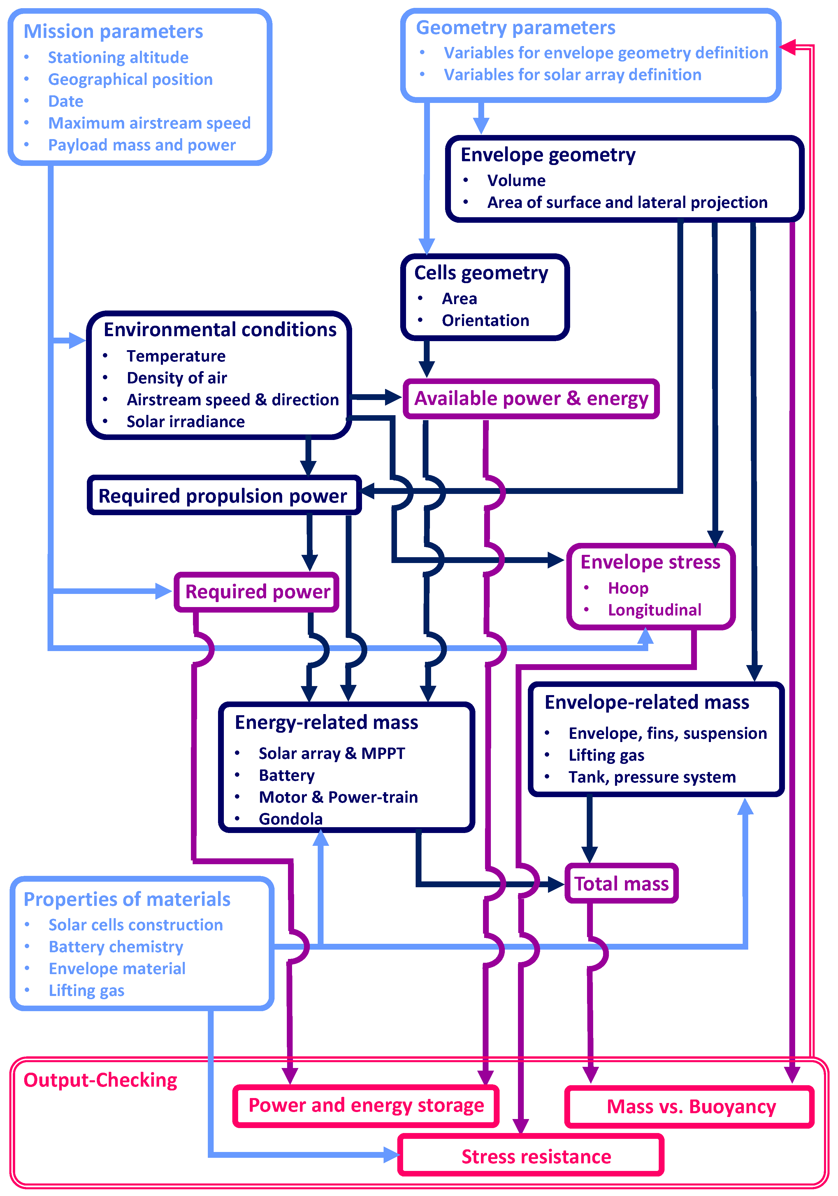
Figure 1. Logical flowchart illustrating the airship design scheme based on a sizing loop and an optimum-seeking loop.
Aerospace 11 00590 g001
Figure 2. Schematic representation of an atmospheric ionic thruster, defining some characteristic geometrical parameters. (Left) side view. (Right) three-quarters view.
Aerospace 11 00590 g002
Figure 3. Basic working topology adopted in the design algorithm.
Aerospace 11 00590 g003
Figure 4. Considered model of the ratio T A m with altitude.
Aerospace 11 00590 g004
Figure 5. Considered model of the ratio T P m with altitude.
Aerospace 11 00590 g005
Figure 6. Geometry of baseline designs. Showing the geometrical sizing of the envelope, solar cells, and thrusters (the latter for ionic cases only). (Top plot) conventionally propelled airship. (Bottom plot) airship featuring atmospheric ionic thrusters.
Aerospace 11 00590 g006
Figure 7. Effect of the target altitude on the weight breakdown. (Top plot) conventionally propelled airship. (Bottom plot) airship featuring atmospheric ionic thrusters.
Aerospace 11 00590 g007
Figure 8. Effect of a change in the envelope material density on the weight breakdown of an airship featuring atmospheric ionic thrusters.
Aerospace 11 00590 g008
Figure 9. Effect of the frontal blockage parameter ξ and of the side of the square front capture area of the atmospheric ionic thruster. (Top plot) ξ = 0.5. (Bottom plot) ξ = 1.
Aerospace 11 00590 g009
Table 1. Basic data for high-altitude mission sizing.
Mission ParameterValue
Flight time48 h
Climb and descent ground speed6 m/s
Top altitude (above ground)17 km
Climb and descent angle (absolute value)30 deg
Table 2. Components of the payload.
SystemWeight [kg]Power [kW]
Data links & Computers100.1
ELM-2022A953.3
AJCN2279.7
MS-1772441.75
Table 3. Assigned values of technological parameters.
ComponentTechnological ParameterValue
EnvelopeSurface density113 g/cm2
Maximum tensile strength970 N/cm
BatteryEnergy density450 Wh/kg
Power density1800 W/kg
Charge/Discharge efficiency96%
CablesVolumetric energy density1150 J/m3
Table 4. Results of weight-optimal sizing for airships based on conventional or atmospheric ionic thrusters. Baseline technology data is assumed for the computations.
QuantityConventionalIonic
Envelope length L r [m]87.0275.7
Fineness ratio F R 3.405.23
Total weight W [kg]386451,889
Envelope W e n v [kg]7724943
Ballonet W b a l [kg]3992257
Lifting gas W l g [kg]6688975
Support structures, tail W s t r + W t [kg]1241370
Thruster W m + W e l [kg]207313
Voltage booster W v b [kg]04052
Battery W b a t [kg]71221,674
Solar cells, MPPT W s c + W M P P T [kg]722358
Gondola W g o n [kg]2474213
Payload W p l [kg]576576
Table 5. Number of thrusters for weight-optimal design solution with atmospheric ionic thrusters, for changing the value of the top altitude (as in the bottom plot of Figure 7).
Altitude h cr N l N t , l N t = N l N t , l
15 km43431849
16 km37431591
17 km30411230
18 km24421008
19 km32551760
20 km35642240
Table 6. Number of thrusters for weight-optimal design solution with atmospheric ionic thrusters, for changing the value of the blockage parameter and frontal area sizing (as in Figure 9).
Frontal Area Side s = w [m]Blockage Parameter ξ N c N l N t , l N t = N l N t , l
2.00.580146304380
2.018030411230
2.50.510086201720
2.511002232704
3.00.51206015900
3.011201826468
Disclaimer/Publisher’s Note: The statements, opinions and data contained in all publications are solely those of the individual author(s) and contributor(s) and not of MDPI and/or the editor(s). MDPI and/or the editor(s) disclaim responsibility for any injury to people or property resulting from any ideas, methods, instructions or products referred to in the content.