Cooling of 1 MW Electric Motors through Submerged Oil Impinging Jets for Aeronautical Applications
Abstract
1. Introduction
2. Review of Cooling Technologies
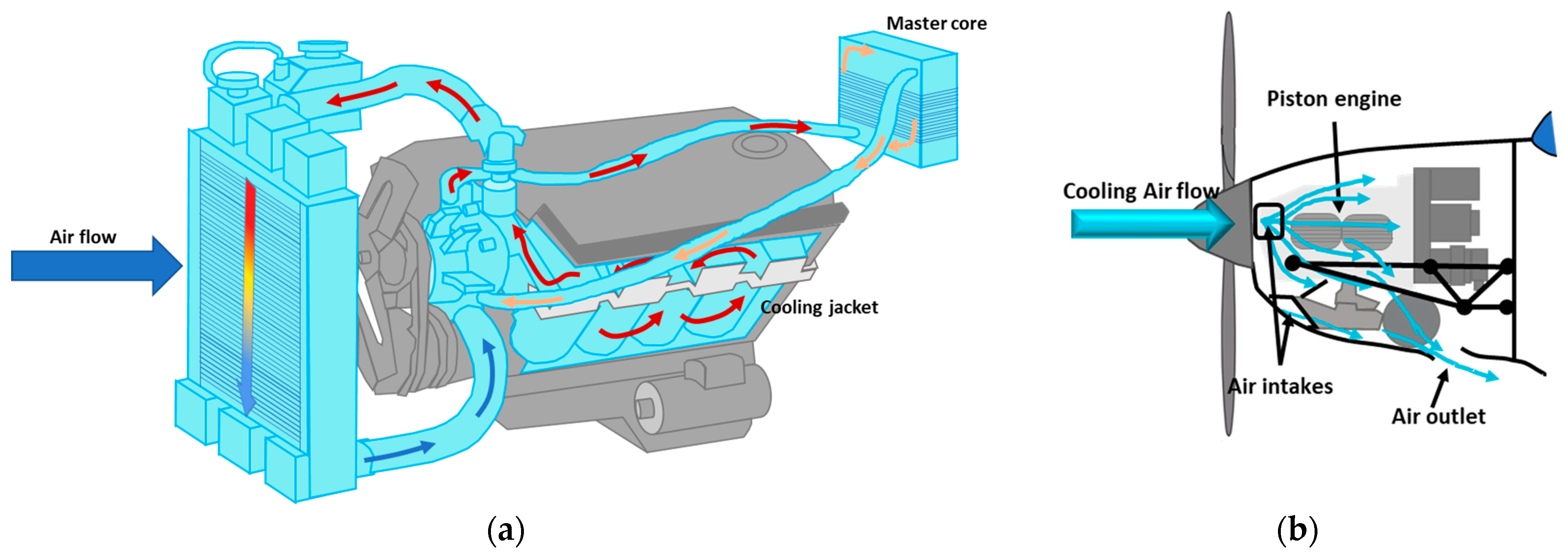
- Forced air cooling systems: These systems adopt the same principle as liquid cooling systems [17], using air as a coolant to transfer heat from the source to the external ambient [21]. As for liquid cooling systems, air cooling systems (see Figure 1b) have been applied to existing piston aircraft [22], even if it is less effective during low-speed operations (i.e., ground operations, take-off, holding, and all the other high-power/low-speed operations). This type of cooling is commonly used in electric motors, where air is circulated over the surface of the motor to dissipate heat. Studies explore factors influencing cooling effectiveness, such as fan design, airflow, and heatsink configurations. While ensuring construction simplicity and reduced weights, this approach cannot easily guarantee heat dissipation in the reference volumes. TRL is higher than 7.
- Passive systems: Such cooling systems use fluid moving in a closed case to cool down the equipment. There are three different typologies of passive systems [21]:
- ○
- Heat pipes: Refrigeration fluid is heated by the heat source, changing phase (from liquid to vapour), thus absorbing heat. The vapour moves from the hot to the cold zone, condensing and releasing heat outside;
- ○
- Thermosyphons are similar to heat pipes but use gravity and natural convection;
- ○
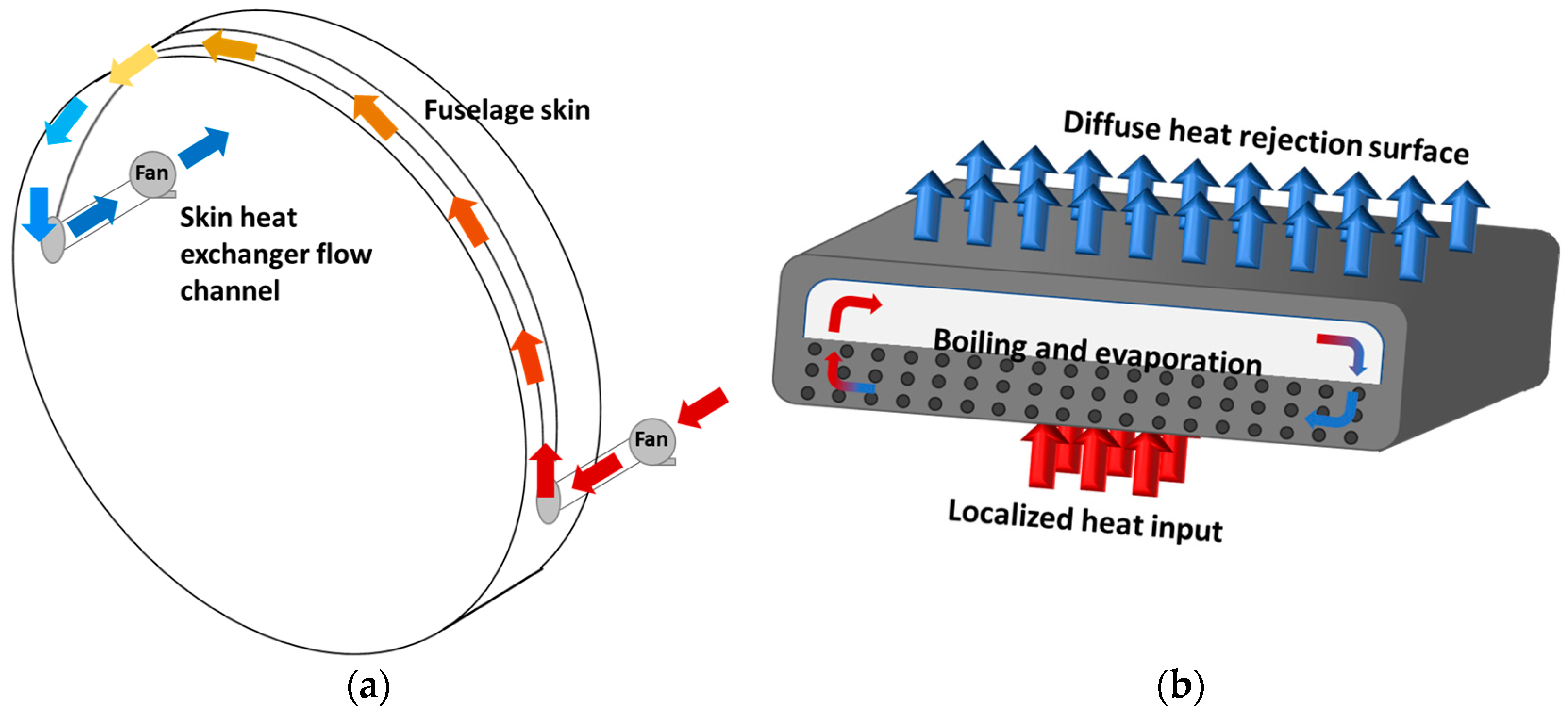
- Vapour chambers are flat heat pipes that transfer heat in 3-D.
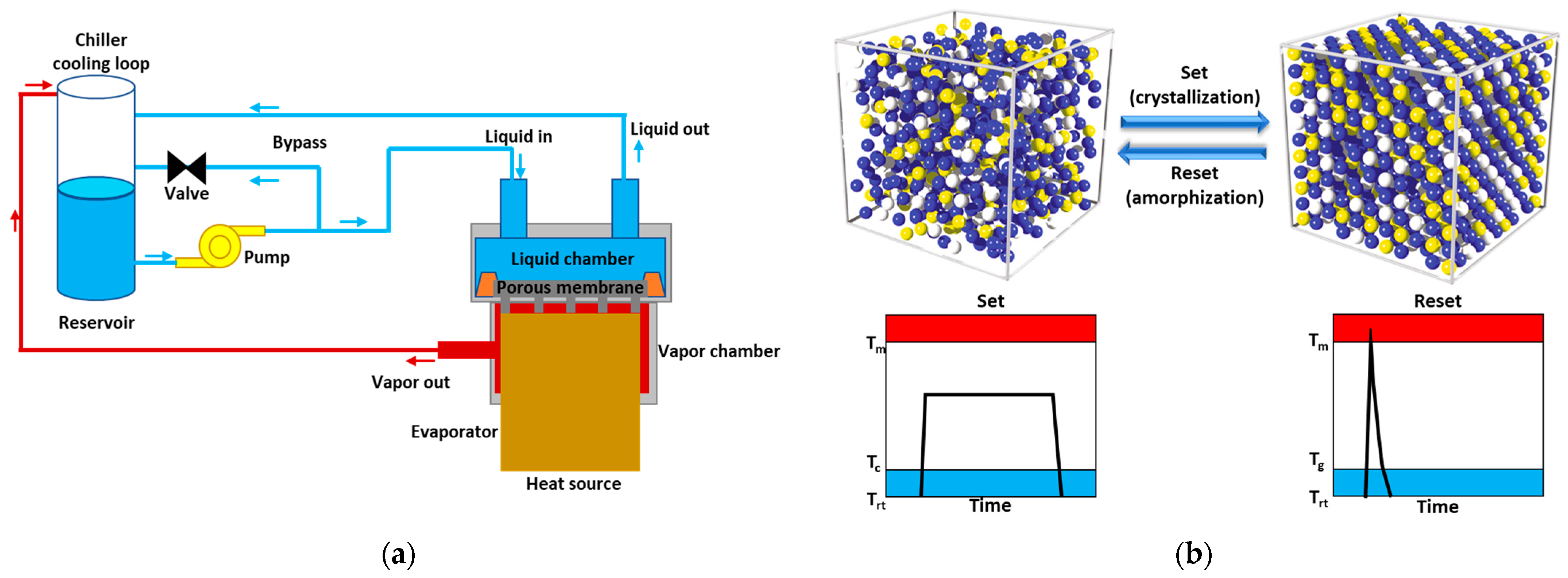
- Phase Change Materials (PCMs) are gaining importance as passive cooling solutions for electric motors. PCMs absorb and release heat during phase transitions, maintaining a stable temperature within the motor [24]. Studies investigate suitable types of PCMs, their encapsulation methods, and their integration within motor systems. Figure 3b shows the crystalline configuration of a generic PCM in the heat absorption and release phase, with the temperature curves as a function of time [25].PCMs are very effective for lowering the temperature locally, but mainly for transient conditions. Various problems [26,27] have been detected regarding the material to be used, assuring a melting temperature of 450 K, suitable for our applications, and above all, the maximum amount of heat they can dissipate. The TRL of PCM ranges between 4 and 6.
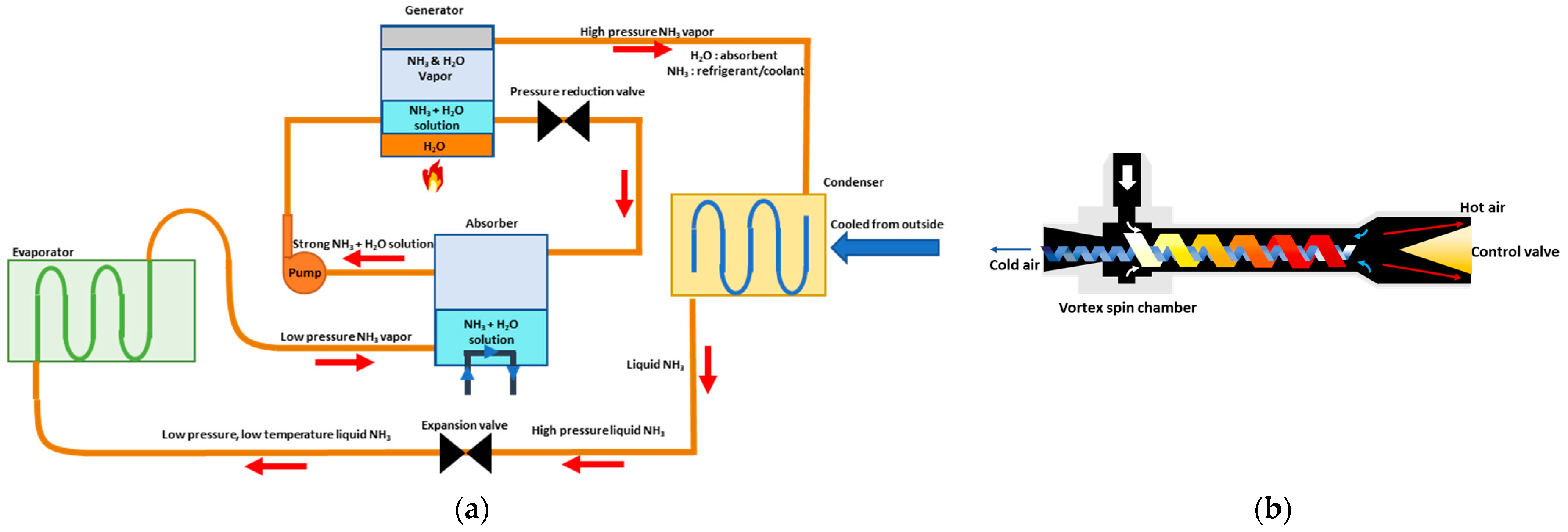
- Absorption refrigerator: Such systems, whose TRL ranges between 4 and 5, are driven using low-quality heat, as seen from [28]. Coolant is inserted in the evaporator, which absorbs heat from the component to cool down and changes its phase into vapour (see Figure 4a). This vapour enters the absorber at low pressure, reacting with another fluid (e.g., water) to form a compound at higher pressure without any compressor. A pump directs this mixture to a generator, which is heated by a low-quality heat source (e.g., a hot system). This heat adduction induces the separation of water vapour from the coolant vapour. A proper filter separates these two vapours: water vapour is sent back to the absorber, while the coolant goes to the condenser where it condenses, moving into the liquid phase.
- Vortex tube: This system, shown in Figure 4b, also known as the Ranque–Hilsch tube, is a mechanical device that separates compressed gas of homogeneous temperature in a stream hotter (up to +200 °C) than the incoming flow and another cooler one (up to −50 °C) simultaneously [29]. Thanks to the geometry of the tube, which includes a control valve, an outlet, and a spin chamber, the TRL is lower than 4.
- Thermoelectric effects: Some materials show a coupled thermal/electric behaviour, enabling direct conversion between electrical and thermal energy. There are two types of thermoelectric effects in Figure 5a:
- ○
- Peltier effect: The thermoelectric material heats up or cools down at an electrified junction [30];
- ○
- Seebeck effect: The thermoelectric material converts heat directly to electricity.
Thermoelectric materials have poor power density and efficiency. Their TRL is between 3 and 4, although some thermoelectric generators are already used in the aerospace sector [31]. - Caloric materials: This type of materials generates cooling effects by the influence of magnetic (magnetocaloric materials), electric (electrocaloric materials), or mechanical (mechanocaloric materials) forces, using a reversible transformation. The TRL is between 2 and 3. In Figure 6a, a schematic of the principle of the magnetocaloric effect is shown.
- Joule–Thomson effect: If a highly compressed gas suddenly expands, the pressure reduction lowers rapidly (almost immediately) the temperature of the gas, which can be used as a heat extractor from a heat source. TMSs based on such an effect are generally utilised on coolers to allow cryogenic performances. The system consists of a fluid isolated in a volume (see Figure 6b), cooled using a proper heat sink, before entering an isolated chamber, where there is a nozzle for sudden gas expansion through a valve into the isolated chamber itself. The expansion rapidly reduces fluid temperature, creating a very cold volume, which cools down the hot source. The TRL ranges between 1 and 3.
- Cryo-cooling systems: In Figure 7a, this type of system uses cryo-refrigerants to remove large amounts of heat, reaching cryogenic temperatures [33]. To remove this heat, these systems can be based on both boiling or sublimation phenomena at low temperatures (depending on the coolant used: liquid or solid). A standard system is the so-called Reverse Bryton Cycle Cryocooler (RBCC). The TRL is between 1 and 3.
- Thermoacoustic heat engines: These systems (see Figure 7b) are composed of a resonator filled with a working fluid and heat exchangers in a tube. Their geometry is studied to convert heat into small air vibrations (i.e., acoustic power). The TRL is between 1 and 3.
3. Cooling Methodologies for High Power Electric Motor
3.1. Description of Oil Cooling Techniques for the 1 MW PM Electrical Machine
3.2. Submerged Jets Oil Cooling Techniques
4. Design and CFD Analysis of Motor Cooling System
4.1. PM Electrical Machine Short Description
4.2. TMS Design
4.3. Simulations Setup
4.3.1. Governing Equations and Mesh Details
| Mass equation | |
| Momentum equation | |
| Energy equation |
- ρ: density [kg/m3]
- h: sensible enthalpy, [kJ/kgK]
- k: thermal conductivity [W/mK]
- T: temperature
- Sh: volumetric heat source.
4.3.2. Thermophysical Properties
4.3.3. Test Matrix for CFD Analyses
- Oil flow rate (0.5−1 m/s);
- Holes number;
- Holes position;
- Hole diameter (2−4 mm);
- Position and diameter of the oil outlet from the machine;
- Rotation speed (0 rpm < n < 20,000 rpm);
- Oil inlet temperature (37–70 °C).
4.4. CFD Results
5. Conclusions and Remarks
Author Contributions
Funding

Data Availability Statement
Acknowledgments
Conflicts of Interest
Abbreviations
| 3D | Three-Dimensional |
| ACARE | Advisory Council for Aviation Research and Innovation in Europe |
| ATF | Automatic Transmission Fluid |
| ATR | Avions de Transport Régional |
| CFD | Computational Fluid Dynamics |
| CIRA | Centro Italiano Ricerche Aerospaziali |
| CO2 | Carbon Dioxide |
| EC | European Commission |
| EG | Electric Generator |
| EM | Electric Motor |
| EPS | Electric Power System |
| EU | European Union |
| GA | General Aviation |
| HTC | Heat Transfer Coefficient |
| ICE | Internal Combustion Engine |
| IPCC | Intergovernmental Panel on Climate Change |
| NOX | Nitrogen Oxide |
| Nu | Nusselt number |
| ORCHESTRA | Optimised Electric Network Architectures and Systems for More-Electric Aircraft |
| PCM | Phase Change Material |
| PM | Permanent Magnet |
| RANS | Reynolds Averaged Navier–Stokes (equations) |
| RBCC | Reverse Bryton Cycle Cryo-Cooler |
| TMS | Thermal Management System |
| TRL | Technology Readiness Level |
| UNOTT | University of Nottingham |
| WSS | Wall Shear Stress |
References
- Chapman, L. Transport and climate change: A review. Journal of Transport Geography 2007, 15, 354–367. [Google Scholar] [CrossRef]
- ICAO Global Environmental Trends–Present and Future Aircraft Noise and Emissions. ICAO A40-WP/54, 05/07/2019. Available online: https://www.icao.int/environmental-protection/Pages/Environmental-Trends.aspx (accessed on 1 April 2024).
- Summary for Policymakers—Global Warming of 1.5 °C. Available online: https://www.ipcc.ch/sr15/chapter/spm/ (accessed on 1 April 2024).
- A Clean Planet for All. Available online: https://eur-lex.europa.eu/legal-content/EN/TXT/HTML/?uri=CELEX:52018DC0773 (accessed on 1 April 2024).
- European Parliament Resolution of 28 November 2019 on the Climate and Environment Emergency. Available online: https://www.europarl.europa.eu/doceo/document/TA-9-2019-0078_EN.html (accessed on 1 April 2024).
- The European Green Deal, Communication from the Commission Brussels. 11 December 2019. Available online: https://eur-lex.europa.eu/legal-content/EN/TXT/HTML/?uri=CELEX:52019DC0640&from=ET (accessed on 1 April 2024).
- A New Industrial Strategy for Europe, European Commission, Brussels. 10 March 2020. Available online: https://eur-lex.europa.eu/legal-content/EN/TXT/PDF/?uri=CELEX:52020DC0102 (accessed on 1 April 2024).
- Time for Change–The Need to Rethink Europe’s FlightPath 2050. ACARE 2020. Available online: https://www.acare4europe.org/wp-content/uploads/2022/02/Time_for_change_FlightPath_2050.pdf (accessed on 5 April 2024).
- Aircraft Technology Net Zero Roadmap. Available online on IATA. Available online: https://www.iata.org/contentassets/8d19e716636a47c184e7221c77563c93/aircraft-technology-net-zero-roadmap.pdf (accessed on 1 April 2024).
- Frosina, E.; Caputo, C.; Marinaro, G.; Senatore, A.; Pascarella, C.; Di Lorenzo, G. Modelling of a Hybrid-Electric Light Aircraft. Energy Procedia 2017, 126, 1155–1162. [Google Scholar] [CrossRef]
- Frosina, E.; Senatore, A.; Palumbo, L.; Di Lorenzo, G.; Pascarella, C. Development of a Lumped Parameter Model for an Aeronautic Hybrid Electric Propulsion System. Aerospace 2018, 5, 105. [Google Scholar] [CrossRef]
- Di Lorenzo, G.; Frosina, E.; De Petrillo, L.; Pascarella, C. Design and Development of Hybrid-Electric Propulsion Model for Aeronautics. MATEC Web Conf. 2019, 304, 3–12. [Google Scholar] [CrossRef][Green Version]
- Marinaro, G.; Di Lorenzo, G.; Pagano, A. From a Battery-Based to a PEM Fuel Cell-Based Propulsion Architecture on a Lightweight Full Electric Aircraft: A Comparative Numerical Study. Aerospace 2022, 9, 408. [Google Scholar] [CrossRef]
- Spakovszky, Z.S.; Chen, Y.; Greitzer, E.M.; Cordero, Z.C.; Lang, J.H.; Kirtley, J.L.; Perreault, D.J.; Andersen, H.N.; Qasim, M.M.; Cuadrado, D.G.; et al. A Megawatt-Class Electrical Machine Technology Demonstrator for Turbo-Electric Propulsion. In Proceedings of the AIAA AVIATION 2023 Forum, San Diego, CA, USA, 12–16 June 2023. [Google Scholar] [CrossRef]
- ORCHESTRA Project Fact Sheet. Available online: https://cordis.europa.eu/project/id/101006771 (accessed on 15 March 2024).
- Konovalov, D.; Tolstorebrov, I.; Eikevik, T.M.; Kobalava, H.; Radchenko, M.; Hafner, A.; Radchenko, A. Recent Developments in Cooling Systems and Cooling Management for Electric Motors. Energies 2023, 16, 7006. [Google Scholar] [CrossRef]
- Bencs, P.; Alktranee, M. The potential of vehicle cooling systems. J. Phys. Conf. Ser. 2021, 1935, 012012. [Google Scholar] [CrossRef]
- Keuter, R.J.; Niebuhr, F.; Nozinski, M.; Krüger, E.; Kabelac, S.; Ponick, B. Design of a Direct-Liquid-Cooled Motor and Operation Strategy for the Cooling System. Energies 2023, 16, 5319. [Google Scholar] [CrossRef]
- Coutinho, M.; Afonso, F.; Souza, A.; Bento, D.; Gandolfi, R.; Barbosa, F.R.; Lau, F.; Suleman, A. A Study on Thermal Management Systems for Hybrid–Electric Aircraft. Aerospace 2023, 10, 745. [Google Scholar] [CrossRef]
- Technology Readiness Levels (TRL). Available online: https://www.esa.int/Enabling_Support/Space_Engineering_Technology/Shaping_the_Future/Technology_Readiness_Levels_TRL (accessed on 1 April 2024).
- Zhang, Z.; Wang, X.; Yan, Y. A review of the state-of-art in electronic cooling. E-Prime-Adv. Electr. Eng. Electron. Energy 2021, 1, 10009. [Google Scholar] [CrossRef]
- Van Heerden, A.S.J.; Judt, D.M.; Jafari, S.; Lawson, C.P.; Nikolaidis, T. Aircraft thermal management: Practices, technology, system architectures, future challenges, and opportunities. Aerosp. Sci. 2022, 128, 100767. [Google Scholar] [CrossRef]
- Zhang, P.; Wei, X.; Yan, L.; Xu, H.; Yang, T. Review of recent developments on pump-assisted two-phase flow cooling technology. Appl. Therm. Eng. 2019, 150, 811–823. [Google Scholar] [CrossRef]
- Zalba, B.; Marin, J.M.; Cabeza, L.F.; Mehling, H. Review on Thermal Energy Storage with Phase Change: Materials, Heat Transfer Analysis and Applications. Appl. Therm. Eng. 2003, 23, 251–258. [Google Scholar] [CrossRef]
- Humphries, H.R.; Griggs, E.I. A Design Handbook for Phase Change Thermal Control and Energy Storage Devices; National Aeronautics and Space Administration: Washington, DC, USA, 1977. [Google Scholar]
- Kürklü, A.; Wheldon, A.; Hadley, P. Mathematical Modelling of the Thermal Performance of a Phase-Change Material (PCM) Store: Cooling Cycle. Appl. Therm. Eng. 1996, 16, 613–623. [Google Scholar] [CrossRef]
- Nayak, K.C.; Saha, S.K.; Srinivasan, K.; Dutta, P. A numerical model for heat sinks with phase change materials and thermal conductivity enhancers. Int. J. Heat Mass Transf. 2006, 49, 1833–1844. [Google Scholar] [CrossRef]
- Nikbakthi, R.; Wang, Z.; Hussein, A.K.; Iranmanesh, A. Absorption cooling systems – Review of various techniques for energy performance enhancement. Alex. Eng. J. 2020, 59, 707–738. [Google Scholar] [CrossRef]
- Gupta, U.S.; Chaturvedi, A.; Patel, N. A review on vortex tube refrigeration and applications. Int. J. Adv. Res. Sci. Eng. (IJARSE) 2017, 6, 167–175. [Google Scholar]
- Tsutsui, M.; Yokota, K.; Hsu, W.L.; Garoli, D.; Daiguij, H.; Kawai, T. Peltier cooling for thermal management in nanofluidic devices. Device 2024, 2, 100188. [Google Scholar] [CrossRef]
- Zhao, D.; Tan, G. A review of thermoelectric cooling: Materials, modeling and applications. Appl. Therm. Eng. 2014, 66, 15–24. [Google Scholar] [CrossRef]
- Fernandez, J.G.; Etesse, G.; Comesaña, E.; Seoane, N.; Zhu, X.; Hirakawa, K.; Garcia-Loureiro, A.; Bescond, M. Optimization of thermionic cooling semiconductor heterostructures with deep learning techniques. In Proceedings of the 2023 International Conference on Simulation of Semiconductor Processes and Devices (SISPAD), Kobe, Japan, 27–29 September 2023; pp. 281–284. [Google Scholar] [CrossRef]
- de Waele, A.T.A.M. Basics of Joule–Thomson Liquefaction and JT Cooling. J. Low Temp. Phys. 2017, 186, 385–403. [Google Scholar] [CrossRef]
- Rehman, Z.; Seong, K. Three-D Numerical Thermal Analysis of Electric motor with Cooling Jacket. Energies 2018, 11, 92. [Google Scholar] [CrossRef]
- Staton, D.A.; Cavagnino, A. Convection Heat Transfer and Flow Calculations Suitable for Electric Machines Thermal Models. IEEE Trans. Ind. Electron. 2008, 55, 3509–3516. [Google Scholar] [CrossRef]
- Harahap, F.; McManus, J.H.N. Natural Convection Heat Transfer from Horizontal Rectangular Fin Arrays. J. Heat Transf. 1967, 89, 32–38. [Google Scholar] [CrossRef]
- Valenzuela, M.A.; Tapia, J.A. Heat Transfer and Thermal Design of Finned Frames for TEFC Variable-Speed Motors. IEEE Trans. Ind. Electron. 2008, 55, 3500–3508. [Google Scholar] [CrossRef]
- Gnielinski, V. New Equations for Heat and Mass Transfer in Turbulent Pipe and Channel Flow. Int. Chem. Eng. 1976, 16, 359–367. [Google Scholar]
- Seghir-Ouali, S.; Saury, D.; Harmand, S.; Phillipart, O.; Laloy, D. Convective heat transfer inside a rotating cylinder with an axial airflow. Int. J. Therm. Sci. 2006, 45, 1166–1178. [Google Scholar] [CrossRef]
- Womac, D.J.; Ramadhyani, S.; Incropera, F.P. Correlating Equations for Impingement Cooling of Small Heat Sources With Single Circular Liquid Jets. J. Heat Transf. 1993, 115, 106–115. [Google Scholar] [CrossRef]
- Douglas, J.F.; Gasiorek, J.M.; Swaffield, J.A. Fluid Mechanics; Longman: Singapore, 1995. [Google Scholar]
- Murakami, M.; Kikuyama, K. Turbulent Flow in Axially Rotating Pipes. J. Fluids Eng. 1980, 102, 97–103. [Google Scholar] [CrossRef]
- Yamada, Y. Resistance of a Flow through an Annulus with an Inner Rotating Cylinder. Bull. JSME 1962, 5, 302–310. [Google Scholar] [CrossRef]
- Bourgault, J.; Roy, P.; Eshaan, G.; Narayan, C.K. A Survey of Different Cooling Methods for Traction Motor Application. In Proceedings of the 2019 IEEE Canadian Conference of Electrical and Computer Engineering (CCECE), Edmonton, AB, Canada, 5–8 May 2019. [Google Scholar]
- Di Lorenzo, G.; Manca, O.; Nardini, S.; Ricci, D. Laminar confined impinging slot jets with nanofluids on heated surfaces. In Proceedings of the 2011 17th International Workshop on Thermal Investigations of ICs and Systems (THERMINIC), Paris, France, 27–29 September 2011; Volume 6, pp. 1–6. [Google Scholar]
- Di Lorenzo, G.; Manca, O.; Nardini, S.; Ricci, D. Numerical study of laminar confined impinging slot jets with nanofluids. Adv. Mech. Eng. 2012, 4, 248795. [Google Scholar] [CrossRef]
- Manca, O.; Ricci, D.; Nardini, S.; Di Lorenzo, G. Thermal and fluid dynamic behaviors of confined laminar impinging slot jets with nanofluids. Int. Commun. Heat Mass Transf. 2016, 70, 15–26. [Google Scholar] [CrossRef]
- Carriero, A.; Locatelli, M.; Ramakrishnan, K.; Mastinu, G.; Gobbi, M. A Review of State of the Art of Electric Traction Motors Cooling Techniques; SAE International: Warrendale, PA, USA, 2018; ISSN 0148-7191. [Google Scholar]
- Bennion, K.; Cousineau, J.; Moreno, G. Electric Motor Thermal Management for Electric Traction Drives; SAE 2014 Thermal Management Systems Symposium: Denver, CO, USA, 2014. Available online: https://www.nrel.gov/docs/fy15osti/62919.pdf (accessed on 29 May 2024).
- Molana, M.; Banooni, S. Investigation of Heat Transfer Processes Involved Liquid Impingement Jets: A Review; Department of Mechanical Engineering, Engineering Faculty, Shahid Chamran University: Ahvaz, Iran, 2013. [Google Scholar]
- Léal, L.; Miscevic, M.; Lavieille, P.; Amokrane, M.; Pigache, F.; Topin, F.; Nogarède, B.; Tadrist, L. An overview of heat transfer enhancement methods and new perspectives: Focus on active methods using electroactive materials. Int. J. Heat Mass Transfer. 2013, 61, 505–524, Preprint submitted to Elsevier (2012). [Google Scholar] [CrossRef]
- Zuckerman, N.; Lior, N. Jet Impingement Heat Transfer: Physics, Correlations, and Numerical Modeling. Adv. Heat Transf. 2006, 39. [Google Scholar] [CrossRef]
- Jambunathan, K.; Lai, E.; Moss, M.A.; Button, B.L. A review of heat transfer data for single circular jet impingement. Int. J. Heat Fluid Flow 1992, 13, 106–115. [Google Scholar] [CrossRef]
- Gardon, R.; Carbonpue, J. Heat transfer between a flat plate and jets of air impinging on it. Int. Dev. Heat Transf. 1962, 2, 454–460. [Google Scholar]
- Popiel, C.O.; Trass, O. The effect of ordered structure of turbulence on momentum, heat, and mass transfer of impinging round jets. In Proceedings of the International Heat Transfer Conference 7, Munchen, Germany, 6–10 September 1982; Volume 6, pp. 141–146. [Google Scholar]
- Tso, J.; Hussain, F. Organized motions in a fully developed turbulent axisymmetric jet. J. Fluid Mech. 1989, 203, 425–448. [Google Scholar] [CrossRef]
- Feng, X.; Cousineau, E.; Bennion, K.; Moreno, G.; Kekelia, B.; Narumanchi, S. Experimental and Numerical Study of Heat Transfer Characteristics of Single-Phase Free-Surface Fan Jet Impingement with Automatic Transmission Fluid; Elsevier: Amsterdam, The Netherlands, 2020. [Google Scholar]
- Kim, J. Spray cooling heat transfer: The state of the art. Int. J. Heat Fluid Flow 2007, 28, 753e767. [Google Scholar] [CrossRef]
- Jones, W.P.; Launder, B.E. The prediction of laminarization with a two-equation model of turbulence. Int. J. Heat Mass Transf. 1972, 15, 301–314. [Google Scholar] [CrossRef]
- Menter, F.R. Two-Equation Eddy-Viscosity Turbulence Models for Engineering Applications. AIAA J. 1994, 32, 1598–1605. [Google Scholar] [CrossRef]
- Jones, W.P.; Launder, B. The calculation of low-Reynolds number phenomena with a two-equation model of turbulence. Int. J. Heat Mass Transf. 1973, 16, 1119–1130. [Google Scholar] [CrossRef]








| Natural Cooling | Ref. | ||
| Cylinder housing | [35] | ||
| Finned housing | [36] | ||
| Forced Cooling | |||
| Cylinder housing | [35] | ||
| Finned housing | [37] | ||
| Housing jacket | [38] | ||
| Rotational hallow shaft | [39] | ||
| Spray cooling | [40] | ||
| Friction Loss Coefficient | Ref. | |
| Stationary pipe | [41] | |
| Rotating shaft | [42] | |
| Air gap | [42] | |
| Rotor ducts | [43] | |
| Sudden Expansion, Contraction Loss Coefficient | ||
| Stationary pipe | [41] | |
| Entrance of air-gap | [42] | |
| Entrance of rotor ducts | [43] | |
| Fluid | Thermal Conductivity λ [W/mK] | Specific Heat cp [kJ/kgK] | Density ρ [kg/m3] | Kinematic Viscosity υ [m2/s] |
|---|---|---|---|---|
| Air (@ sea level) | 0.0264 | 1.006 | 1.1174 | 1.57 × 10⁻⁵ |
| Water | 0.56 | 4.217 | 1000 | 1.78 × 10⁻⁶ |
| EGW 50/50 | 0.37 | 3.0 | 1088 | 7.81 × 10⁻⁶ |
| EGW 60/40 | 0.34 | 3.2 | 1100 | 1.36 × 10⁻⁵ |
| Engine Oil | 0.147 | 1.796 | 899 | 4.28 × 10⁻³ |
| Mobil jet oil | 0.149 | 1.926 | 1014 | 1.88 × 10⁻⁴ |
| Paratherm LR | 0.1532 | 1.925 | 778 | 3.43 × 10⁻⁶ |
| PGW 50/50 | 0.35 | 3.5 | 1050 | 1.90 × 10⁻⁵ |
| PGW 60/40 | 0.28 | 3.25 | 1057 | 3.31 × 10⁻⁵ |
| Dynalene HF-LO | 0.1126 | 2.019 | 778 | 3.20 × 10⁻⁶ |
| Brayco Micronic | 0.1344 | 1.897 | 835 | 1.35 × 10⁻⁵ |
| RF 245 FA | 0.014 | 0.975 | 10.51 | 1.03 × 10⁻⁵ |
| Silicone KF 96 | 0.15 | 1.5 | 1000 | 8.00 × 10⁻⁵ |
| Skydrol 500-4 | 0.1317 | 1.75 | 1000 | 3.50 × 10⁻⁶ |
| Id. | Description | Value |
|---|---|---|
| Q1 [kW] | Thermal power—Winding | 14.3 |
| Q2 [kW] | Thermal Power—Stator | 2.02 |
| Q3 [kW] | Stator teeth Thermal Power | 1.75 |
| A1 [m2] | Surface Winding | 0.0002 |
| A2 [m2] | Surface Stator | 0.000273 |
| A3 [m2] | Surface teeth | 0.001449 |
| V1 [m3] | Volume winding | 3.14 × 10⁻⁵ |
| V2 [m3] | Volume stator | 0.000027 |
| q1 [MW/m3] | Thermal power density winding | 11.034 |
| q2 [MW/m3] | Thermal power density Stator | 1.340 |
| q3 [MW/m3] | Thermal power density stator teeth | 0.0252 |
| Boundary Conditions | Zones |
|---|---|
| MASS FLOW INLET | inlet holes |
| OUTFLOW | exit hole |
| MOVING WALL | external rotor surfaces |
| WALL/no Slip | the remainder |
| Constant heat flux | teeth |
| Uniform heat power source (W/m3) | stator yoke, end-winding, copper |
| Id. | Configuration Status 1 | Configuration Status 2 | Nr. Cells |
|---|---|---|---|
| Mesh 1 | d = 2 mm | Without Epoxy Resin | 20M |
| Mesh 2 | d = 2 mm | With Epoxy Resin | 15M |
| Mesh 3 | d = 4 mm | Without Epoxy Resin | 20M |
| Mesh 4 | d = 4 mm | With Epoxy Resin | 15M |
| Solid Material Property | Value |
|---|---|
| NKM—slot liner | |
| Density [kg/m3] | 395 |
| Cp [J/(kg-K)]—Specific heat | 1200 |
| k [W/(m-K)]—Thermal conductivity | 0.14 |
| Recoma33—magnet | |
| Density [kg/m3] | 8300 |
| Cp [J/(kg-K)]—Specific heat | 350 |
| k [W/(m-K)]—Thermal conductivity | 10 |
| Resin—insulator | |
| Density [kg/m3] | 2500 |
| Cp [J/(kg-K)]—Specific heat | 784 |
| k [W/(m-K)]—Thermal conductivity | 0.8 |
| Steel—shaft | |
| Density [kg/m3] | 8030 |
| Cp [J/(kg-K)]—Specific heat | 502.48 |
| k [W/(m-K)]—Thermal conductivity | 16.27 |
| Aluminum—external case | |
| Density [kg/m3] | 2719 |
| Cp [J/(kg-K)]—Specific heat | 871 |
| k [W/(m-K)]—Thermal conductivity | 202.4 |
| Vacoflux48 [CoFe]—stator | |
| Density [kg/m3] | 8120 |
| Cp [J/(kg-K)]—Specific heat | 430 |
| k [W/(m-K)]—Thermal conductivity | 33 |
| Litz—copper wire | |
| Density [kg/m3] | 8890 |
| Cp [J/(kg-K)]—Specific heat | 385 |
| k [W/(m-K)]—Thermal conductivity | 395 |
| Id. Case | d [mm] | Resin between Winding | Rotor Speed [rpm] | Tinlet [K] | Voil [m/s] |
|---|---|---|---|---|---|
| Run 1 | 2 | no | 0 | 325 | 0.5 |
| Run 2 | 2 | no | 20,000 | 325 | 0.5 |
| Run 3 | 2 | no | 0 | 325 | 1.0 |
| Run 4 | 2 | yes | 20,000 | 325 | 0.5 |
| Run 5 | 2 | yes | 20,000 | 325 | 1.0 |
| Run 5_bis | 2 | yes | 0 | 325 | 1.0 |
| Run 6 | 4 | no | 0 | 325 | 0.5 |
| Run 7 | 4 | no | 20,000 | 325 | 0.5 |
| Run 8 | 4 | no | 0 | 325 | 1.0 |
| Run 9 | 4 | yes | 20,000 | 325 | 0.5 |
| Run 10 | 4 | yes | 20,000 | 325 | 1.0 |
| Run 11 | 4 | no | 20,000 | 325 | 1.0 |
| Run 11_bis | 4 | no | 10,000 | 325 | 1.0 |
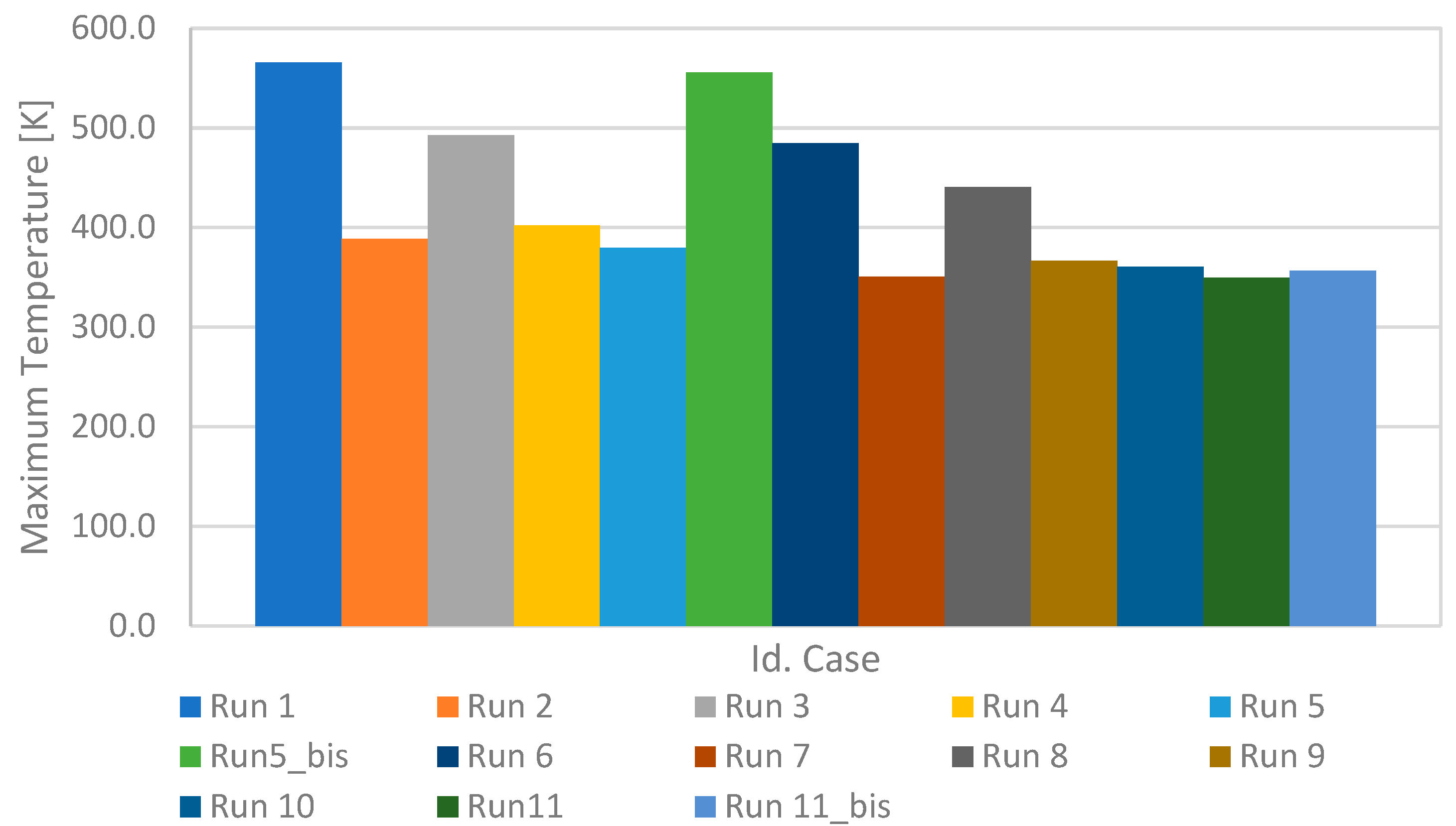
| Id. Case | Vout [m/s] | Tout, ave [K] | Δp [Pa] | τave [Pa] | τmax [Pa] | TMax (stat) [K] | TAve (stat) [K] | TMax (EW) [K] | TAve (EW) [K] | TMax (Teeth) [K] | TAve (Teeth) [K] | L/1′ |
|---|---|---|---|---|---|---|---|---|---|---|---|---|
| Run 1 | 0.574 | 325 | 4.75 | 4.48 × 10⁻³ | 0.33 | 564.7 | 537 | 564.7 | 533 | 565.6 | 539 | 9 |
| Run 2 | 0.570 | 325 | −1.38 × 10³ | 5.45 × 10³ | 41,962.1 | 388.9 | 384 | 388.9 | 383 | 388.9 | 377 | 9 |
| Run 3 | 1.15 | 349 | −1.38 × 10³ | 0.00 | 0 | 491.7 | 465 | 491.7 | 462 | 492.7 | 465 | 18 |
| Run 4 | 0.568 | 372 | 1.26 × 10³ | 1.41 × 10⁴ | 33,516.8 | 402.3 | 395 | 402.3 | 393 | 402.3 | 386 | 9 |
| Run 5 | 1.15 | 325 | −2.82 × 10 | 1.73 × 10⁴ | 35,718.0 | 379.8 | 373 | 379.8 | 370 | 379.8 | 363 | 18 |
| Run 5_bis | 1.16 | 325 | 3.55 | 0.00 | 0.0 | 554.3 | 531 | 554.3 | 527 | 555.4 | 536 | 18 |
| Run 6 | 2.18 | 330 | −5.19 × 10² | 2.97 × 10⁻² | 0.84 | 483.1 | 454.7 | 483.1 | 451 | 484.3 | 456 | 18 |
| Run 7 | 0.542 | 337 | −1.11 × 10³ | 1.12 × 10⁴ | 41,561.2 | 355.2 | 351 | 355.2 | 349 | 350.9 | 343 | 18 |
| Run 8 | 4.36 | 328 | −5.04 × 10² | 1.15 × 10⁻¹ | 2.63 | 439.5 | 415.6 | 439.5 | 413 | 440.5 | 415 | 36 |
| Run 9 | 2.24 | 337 | −3.66 × 10³ | 1.75 × 10⁴ | 39,505.0 | 366.7 | 360 | 366.7 | 358 | 366.7 | 351 | 18 |
| Run 10 | 4.49 | 331 | −1.75 × 10⁴ | 1.76 × 10⁴ | 39,416.0 | 360.8 | 354 | 360.8 | 352 | 360.8 | 345 | 36 |
| Run 11 | 4.36 | 331 | −1.07 × 10³ | 1.13 × 10⁴ | 41,897.5 | 349.5 | 345 | 349.3 | 343 | 349.3 | 337 | 36 |
| Run 11_bis | 4.36 | 331 | −2.48 × 10⁴ | 0.3 × 10⁴ | 11,856.7 | 356.8 | 352 | 356.8 | 350 | 356.8 | 343 | 36 |
Disclaimer/Publisher’s Note: The statements, opinions and data contained in all publications are solely those of the individual author(s) and contributor(s) and not of MDPI and/or the editor(s). MDPI and/or the editor(s) disclaim responsibility for any injury to people or property resulting from any ideas, methods, instructions or products referred to in the content. |
© 2024 by the authors. Licensee MDPI, Basel, Switzerland. This article is an open access article distributed under the terms and conditions of the Creative Commons Attribution (CC BY) license (https://creativecommons.org/licenses/by/4.0/).
Share and Cite
Di Lorenzo, G.; Romano, D.G.; Carozza, A.; Pagano, A. Cooling of 1 MW Electric Motors through Submerged Oil Impinging Jets for Aeronautical Applications. Aerospace 2024, 11, 585. https://doi.org/10.3390/aerospace11070585
Di Lorenzo G, Romano DG, Carozza A, Pagano A. Cooling of 1 MW Electric Motors through Submerged Oil Impinging Jets for Aeronautical Applications. Aerospace. 2024; 11(7):585. https://doi.org/10.3390/aerospace11070585
Chicago/Turabian StyleDi Lorenzo, Giuseppe, Diego Giuseppe Romano, Antonio Carozza, and Antonio Pagano. 2024. "Cooling of 1 MW Electric Motors through Submerged Oil Impinging Jets for Aeronautical Applications" Aerospace 11, no. 7: 585. https://doi.org/10.3390/aerospace11070585
APA StyleDi Lorenzo, G., Romano, D. G., Carozza, A., & Pagano, A. (2024). Cooling of 1 MW Electric Motors through Submerged Oil Impinging Jets for Aeronautical Applications. Aerospace, 11(7), 585. https://doi.org/10.3390/aerospace11070585


