Abstract
Energetic materials, essential for rocket propulsion, play a crucial role in aerospace systems. These materials lack sufficient safety assessments and pose significant risks to life and infrastructure. The slow progress in this field is hindered by prohibitively high experimental costs and the inherently destructive nature of these experiments. This study aimed to evaluate modeling-based safety assessments, primarily utilizing the Lee–Tarver model. It specifically addressed the threat posed by shaped charges during transportation. Experimental analyses employed 50 mm JH-2 shaped charges, targeting RDX-based JH-2 formulation, since RDX is widely used in various rocket motor propellant formulations. TNT was also used to enhance the validation of the Lee–Tarver model findings. Various logistical configurations were explored, testing steel container walls ranging from 10 mm thickness to reinforced walls of 50 mm, 60 mm, and 65 mm steel. Comparative analysis with experiments reinforced the accuracy of the Lee–Tarver model’s numerical predictions. Both simulations and experiments affirmed that a 65 mm steel protection suffices for the safe transportation of RDX-based JH-2 formulations and TNT within a 10 mm storage box in logistical setups. Furthermore, this study emphasizes the Lee–Tarver model’s reliability for most energetic materials safety assessments, while acknowledging certain limitations.
1. Introduction
Energetic materials, the engines driving progress in diverse sectors from industrial blasting and mining operations to military advancements, present a double-edged sword [1]. While their controlled explosions propel us forward, their inherent instability can lead to catastrophic accidents. The devastating 1917 explosion in Halifax Harbor, Canada, serves as a stark reminder of the potential consequences when safety protocols fail. This incident, where a collision between a munitions ship and another vessel resulted in roughly 5000 deaths, is just one of many historical tragedies [2]. NATO data further underscore the persistent threat, revealing an average of one stored energetic materials incident every five years in the US alone between 1948 and 1994, with a global count of 17 incidents reported in early 2004 [3]. The human cost extends beyond civilian casualties, with military incidents like the series of fires on aircraft carriers claiming hundreds of lives and billions in damages [4]. Recent events like the Critical Camp Doha incident, where a near-obliteration of a battalion occurred due to energetic material hazards, and the Beirut explosion, with its devastating loss of life and infrastructure, highlight the ongoing need for stricter safety measures [5,6,7]. Research by Jialin Li et al. further emphasizes the dangers, demonstrating that dust explosions involving energetic materials from 1913 to 2015 caused significant destruction and casualties across the United States, Japan, Germany, and China [8].
Accidents involving energetic materials highlight the need to reduce their sensitivity without compromising detonation performance. Microstructural features like crystal defects, particle shape and size, polymorphism, and impurities significantly affect explosive sensitivity. For instance, air bubbles increase TNT’s impact sensitivity, while internal fractures and porosity heighten ε-CL20’s sensitivity [9]. Techniques such as the co-agglomeration of crystals can engineer microstructures, leading to higher melting points, increased density, reduced sensitivity, and enhanced detonation properties [10]. M. Anniyappan et al. explored innovative energetic material compositions for safer transportation, handling, and storage [11], while Ian J. Powell described design principles for developing insensitive munitions [12]. Rigorous safety testing is crucial for promoting safer compositions and design principles. Energetic materials face hazards such as heat, humidity, and shock during manufacturing, transportation, storage, and use. Slimane Bekhouche et al. found that humidity and temperature increase sensitivity to impact and friction, while AAL Michalchuk et al. predicted a decrease in impact sensitivity with the flattening of molecules caused by shock in Fox-7 [13,14]. For insensitive munitions (IMs), the extensive IM test documents STANAG 4439 and AOP-39 outline policies for their introduction and assessment [15]. Under this policy, six tests are conducted using Allied Ordnance Publications (AOPs). AOPs 4382 [16] and 4240 [17] detail the test procedures for slow and fast cook-off, respectively, while AOPs 4526 [18], 4396 [19], 4496 [20], and 4241 [21] describe the procedures for shock stimuli, including shaped charge jet impact, sympathetic detonation, fragment impact, and bullet impact safety assessment tests.
These tests are limited to two per specimen in these AOPs due to exorbitant costs and inherent destructiveness. The rapid development of new energetic materials and technologies makes high-cost tests impractical for all emerging materials. Moreover, existing numerical research on energetic materials safety is limited. To address this, we used a numerical approach based on the Lee–Tarver ignition and growth (I&G) model [22], known for effectively simulating diverse energetic materials and predicting initiation thresholds [23]. Widely popular energetic materials, such as TNT, COMP B, RDX, HMX, TATB, and LX-17, have been successfully modeled and simulated using the Lee–Tarver model to study shock initiation [24,25,26]. Furthermore, simulations have successfully examined the shock initiation behavior of liquid phases of pentaerythritol tetranitrate and trinitrotoluene [27]. The Lee–Tarver model was also effectively employed to calculate and simulate the ignition and growth behavior of CL-20 explosives [28]. Despite all these studies, the application of the Lee–Tarver model for the safety assessment of energetic materials is almost nonexistent. Our study included experimental and numerical impact safety investigations, using JH-2 and TNT energetic materials as targets. RDX, which constitutes 95% of JH-2, is crucial in aerospace propulsion systems due to its extensive use in various propellant formulations [29,30]. TNT was used to validate the Lee–Tarver model’s safety predictions.
AOP 4526 tests energetic materials’ response to shaped charge attacks, a major threat due to their high-velocity metal jets (up to 10 km/s) that pierce through Rolled Homogeneous Armor (RHA) and even ultra-high-strength concrete [31,32,33]. In this study, the 50 mm JH-2 shaped charge device, with a jet energy level of 119 mm3/µs2 according to Held’s criteria (slightly lower than the standard value of 120 mm3/µs2 suggested in allied ordnance publication 4526), served as the threat and was both modeled and experimentally utilized. The safety evaluation of energetic materials encompassed empirical and computational methods, accounting for various logistical considerations. These analyses focused on small-scale JH-2 and TNT targets, integrating empirical findings and computational simulations to facilitate a comprehensive examination of energetic materials safety. This combined approach provided deeper insights into the safety characteristics of various materials, supporting the development of effective safety measures. This is particularly important in a field where prior research is inadequate, helping to identify the limitations within which the Lee–Tarver I&G model can be effectively applied. Furthermore, this research endeavor aimed to advocate for the use of Lee–Tarver model safety assessment simulations in both civilian and military applications, thereby mitigating the expenses, time, and detrimental impacts associated with live energetic materials safety tests.
2. Experimental Setup
2.1. The 50 mm Shaped Charge Design
To evaluate the safety characteristics of energetic materials like JH-2 and TNT, we employed a specifically designed shaped charge (Figure 1). This device featured JH-2 explosives and a conical metal liner crafted from OFHC copper, a material known for its exceptional penetration capabilities. The liner had a diameter of 50 mm and a precisely designed 44-degree apex angle, resembling a funnel. An initiator triggered a controlled detonation within JH-2 explosives, generating a powerful pressure wave traveling at approximately 8 km/s in these experiments. This wave adhered to established scientific principles known as Chapman–Jouguet conditions. As the wave propagated through the device, it converged with remarkable focus on the center of the copper liner, inducing its transformation into a high-velocity jet through melting. This jet formation was crucial to the research, as it represented the primary penetrating force of a shaped charge and potentially posed a significant threat. A cone apex angle of 44 degrees was selected to achieve a v2d value of approximately 119 mm3/µs2, closely matching the v2d value suggested in Allied Ordnance Publication 4526.

Figure 1.
(a) Dimensions of the 50 mm shaped charge. (b) Real image of the shaped charge.
2.2. Energetic Materials Safety Assessment Setup
The experiments employed a specially designed setup comprising several crucial components. The first component was the shaped charge, a device previously discussed in our research for representing shaped charge threat. Given the impracticality of testing real containers transporting energetic materials, the effects of container walls were simulated using steel cylinders of varying thicknesses, with 10 mm representing a thin, specially designed container for energetic material transport, while 50 mm, 60 mm, and 65 mm cylinders represented additional protective measures for safer transport.
A steel base cylinder was also included as a witness cylinder to observe detonation evidence. Additionally, spacer cylinders were used to regulate the precise standoff distance between the shaped charge and the target explosive. The core elements of the experiment were the target energetic materials themselves, JH-2 and TNT, both identical in size, with a radius of 22.5 mm and a height of 40 mm, as depicted in Figure 2. This setup facilitated controlled experimentation to evaluate the effects of the shaped charge on the detonation characteristics of the target materials. In these logistical setups, the munition was presumed to be transported within a steel container with different wall thicknesses, as depicted in Figure 3 and Figure 4.

Figure 2.
(a) JH-2 and (b) TNT explosive targets.

Figure 3.
Shaped charge jet attack logistical safety assessment configuration for JH-2 with 50 mm protection and 10 mm container wall: (a) schematic diagram; (b) real image.
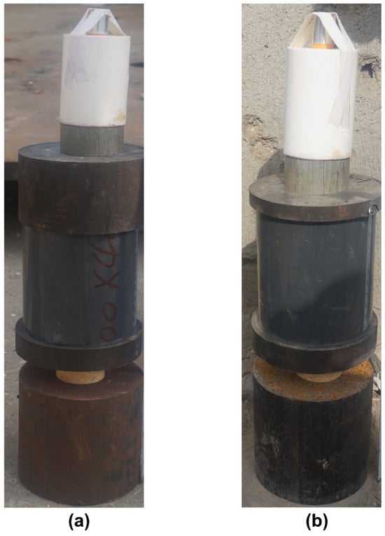
Figure 4.
(a) The 50 mm equivalent protection and (b) 10 mm steel container logistical setups for investigating TNT explosive response.
In these setups, the shaped charge jet initially penetrated the steel container wall before striking the target JH-2 and TNT energetic materials. A 20 mm steel cover plate was positioned in front of the shaped charge, placed at a distance of more than at least 100 mm from the shaped charge, to ensure a controlled environment for the detonation process. This configuration allowed for an assessment of how the shaped charge interacted with the container wall, any protection that was applied, and the subsequent effects on the target materials. By incorporating these additional details into the experimental design, we aimed to simulate realistic scenarios of energetic material transport and detonation, providing valuable insights into safety considerations and mitigation strategies.
2.3. Experimental Velocity and Diameter Measurement Setup via Flash X-rays
Figure 5 provides a depiction of the equipment utilized in this research. One crucial aspect of shaped charge research involves capturing the dynamic behavior of the metallic liner during its collapse and jet formation. Jet tip velocity and diameter were precisely observed and measured using the flash X-ray technique. This approach utilizes two X-ray tubes with precisely timed emissions. This enabled the visualization of the jet at two distinct stages during its evolution, offering valuable insights into its position and shape at each interval. By leveraging the established principle of geometric similarity, researchers could then calculate important jet features such as diameter, average velocity, and length. This combined approach, utilizing time-resolved X-ray imaging and geometric calculations, provided a comprehensive methodology for examining the shaped charge jet’s critical characteristics.

Figure 5.
Flash X-ray setup for velocity and diameter measurements of the jet.
2.4. Baseline Penetration Setup for Assessing Energetic Material Response
In order to understand how detonation affected the steel witness cylinder compared to the typical penetration behavior of a shaped charge jet, a standard baseline penetration test was conducted. These observations served as a crucial foundation for inferring the response of energetic materials. By comparing the baseline penetration images with those obtained from the response of energetic materials placed on the witness cylinder, insights into the materials’ behavior under different logistical configurations were gleaned. This comparative analysis facilitated a comprehensive understanding of how different energetic materials interacted with the attacking jets under different configurations, thereby aiding in the optimization of their performance and safety measures. This test also aimed to highlight how effectively the 50 mm shaped charge could penetrate a target made of 45 steel with a density of 7.85 g per cubic centimeter. The target was a cylinder with a diameter of 100 mm and a height of 250 mm, as depicted in Figure 6. The experiment achieved a penetration depth of 235 mm, very close to the 230 mm predicted by computer simulations.
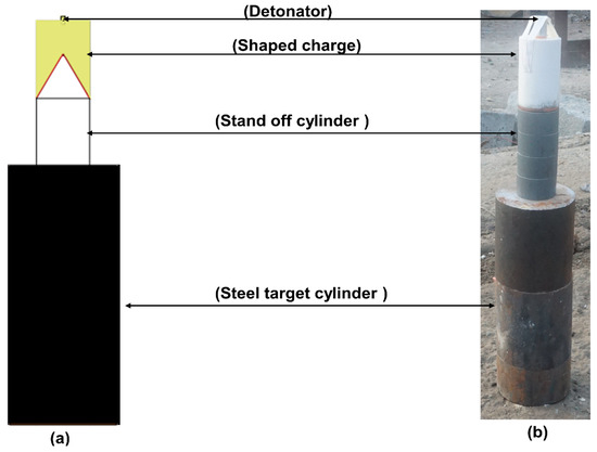
Figure 6.
Baseline test to compare witness cylinders for detonation evidence with different logistical configurations, (a) schematic diagram, (b) real image.
3. Experimental Results
3.1. Velocity and Diameter Measurements of Shaped Charge Jet
The flash X-ray investigation unveiled a velocity of 6.87 km/s and a diameter of 2.5 mm for the shaped charges. These findings were further validated by numerical simulations. Additionally, it was observed that the velocity exhibited a linear change along the jet’s length, as shown in Figure 7. To ensure accurate measurement of v2d values, it is recommended to measure the velocity, behind the jet tip anomalies, and the diameter of the jet.
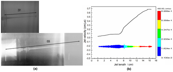
Figure 7.
(a) The 6.87 km/sec measurement of velocity using flash X-rays and (b) 6.869 km/s velocity measurement using AUTODYN, ANSYS 17.1 in a comparable manner.
3.2. JH-2 and TNT Response to the Shaped Charge Jet Attack
Eight experiments were conducted, wherein the TNT and JH-2 targets were attacked with 50 mm caliber shaped charges. The experiments involved subjecting the TNT and JH-2 targets to four different logistical setups to assess safety. In the realm of logistical configurations, a multitude of container arrangements catering to the secure transport of munitions exists. Furthermore, various thicknesses of container walls can be achieved by using add-on steel plates to enhance protection from anticipated attack directions. This study, however, operated under the assumption that the containers were constructed from steel, featuring wall thicknesses of 10 mm (normal), 50 mm, 60 mm, and 65 mm (with the help of add-on steel structures) on the side facing the shaped charge jet during an attack. Additionally, a slender storage box of 10 mm or 20 mm steel thickness was considered in these configurations to store energetic materials. In one special case, all these steel structures were directly connected to the energetic material, forming a barrier of 75 mm steel directly attached to the energetic materials.
The high-speed footage clearly depicted the rapid consumption of the entire energetic substance through the detonation process, as evident in Figure 8 and Figure 9, while Figure 10 shows only the burning of the energetic target material. The JH-2 and TNT burned only in the case of 75 mm steel directly attached to the explosives and, consequently, they were deemed secure, as per the stipulation within AOP 4526 that an explosive is deemed safe if it does not initiate detonation during a shaped charge attack.
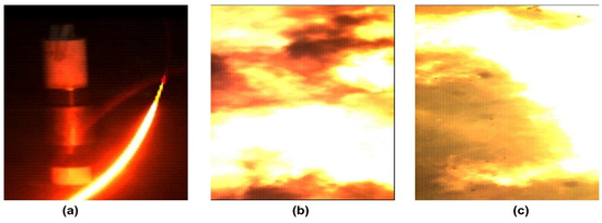
Figure 8.
(a) Safety assessment setup, (b) detonation of shaped charge, and (c) detonation of target.

Figure 9.
(a) Safety assessment setup, (b) detonation of shaped charge, and (c) detonation of target.
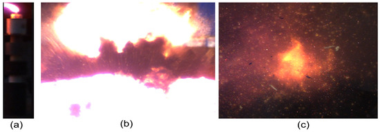
Figure 10.
(a) Safety assessment setup, (b) detonation of shaped charge, and (c) burning of target only.
Additionally, only a cylindrical steel base measuring φ100 × 100 mm was utilized as a witness cylinder, deliberately avoiding complete encapsulation to mitigate the risk of enhanced detonation probability. Table 1 presents the definitive responses of TNT and JH-2 energetic materials observed in the conducted experiments when subjected to a shaped charge jet attack.

Table 1.
Different logistical configurations for TNT and JH-2 energetic materials and their responses.
In instances where a 65 mm steel protection layer was directly affixed with a 10 mm steel cover, the target materials underwent combustion exclusively. This phenomenon arose from the impact of the jet during penetration of the 75 mm total steel length, which compressed the energetic materials, consequently reducing inherent hot spots in the penetration process. This compression rendered the energetic material less sensitive. Conversely, despite the total steel protection surpassing 75 mm in the scenario involving 60 mm steel protection with a 20 mm energetic material cover and a standoff distance between them, the dynamic penetration process failed to compress the JH-2 energetic material. Consequently, sensitivity did not diminish, leading to observed detonation in this case. However, in the same condition, TNT did not detonate because of its inherent decreased sensitivity compared to JH-2.
3.3. Evidence from Witness Steel Cylinder
The steel walls of the containers in the logistical configurations and storage boxes, both of thin steel construction, were readily breached by shaped charge jets when the wall thickness was 10 mm and even when the overall wall thickness was increased to 50 mm with the addition of steel. These jets subsequently impacted the energetic material targets, leading to their detonation. This detonation event was evident in the observed crater on the steel witness cylinder compared to baseline experiments illustrating jet penetration, as shown in Figure 11a,b, with Figure 11c depicting the typical jet penetration pattern in a steel cylinder. The detonation process of the energetic materials is delineated in Figure 12a,b, while the burning of energetic materials in the case of steel protection greater than 60 mm, especially in the case of TNT, was clearly discernible by the burn marks on the witness cylinder, as depicted in Figure 12c.

Figure 11.
(a,b) Evidence of JH-2 target detonation, creating craters in a steel witness cylinder under different logistical setups, while (c) represents standard penetration from a shaped charge jet.

Figure 12.
Craters on the steel witness cylinder indicating TNT detonation for different logistical setups (a,b), with burning observed in the logistical configuration (c).
4. Numerical Methods and Simulations
4.1. Numerical Simulations
The development of the jet was replicated through simulations utilizing one of the AUTODYN solvers known as Euler multimaterial. In these simulations, the Euler domain was employed to model the dynamic behavior of both the energetic materials and the liner. To ensure the precise portrayal of physical phenomena, a suitable boundary condition known as the “flow-out boundary” was implemented for all computational limits to prevent reflections while shock waves propagated [34]. A value of 2.066 × 10⁵ J/kg was utilized for internal energy, while 0.1225 × 10⁻² mg/mm3 was employed to represent the density of air filling the free space within the Euler domain surrounding components of various logistical configurations. Jet velocity was measured by positioning fixed gauge points on the axis of symmetry. To ensure simulation stability during penetration into the steel container and its protection by jets, AUTODYN’s Lagrange solver was utilized [35]. Furthermore, to prevent the excessive distortion of grid elements, AUTODYN offers an erosion option, which was activated to ensure that the time step remained adequate. This approach effectively removed distorted elements that could cause degeneracy issues and lead to simulation failure [36]. J. Bolstad and D. Mandell conducted a study on the impact of mesh density on the precision of hydrodynamic analyses and determined that four cells per millimeter yielded results consistent with experimental data [37]. In the current study, centimeters, grams, and microseconds units were necessary due to the I&G model. Therefore, a mesh density of 40 cells per centimeter was utilized, equivalent to 4 cells per millimeter.
4.2. Material Models
4.2.1. JH-2 for Threat Shaped Charge
This study employed JH-2 as the threat shaped charge and target in a 95% RDX-based formulation, while TNT served as an additional target for validating the I&G model. Equations of state (EOS) were employed to accurately depict the behavior of the energetic materials in simulations. One of the most commonly utilized state equations in this context is the Jones–Wilkins–Lee equation, abbreviated as JWL, which is often coupled with a burn model for high explosives [38]. The JWL equation, described by Equation (1), was derived from Lee et al.’s paper [39].
The coefficients of the JWL equation of state are denoted by R1, A, B, ω, and R2. In the case of energetic materials undergoing sustained detonation, the pressure is of the order of hundreds of kilo bars, denoted by “P”, while the relative volume of the energetic material is represented by “V”. Additionally, energy is denoted by E. Table 2 provides specific coefficients and detonation properties for the JH2 energetic material.

Table 2.
JWL parameters of JH-2 energetic material.
4.2.2. Copper Liner and Steel Material Model
To examine the deformation of the liner, the shock–EOS and Steinberg–Guinan models were utilized. The parameters pertinent to the shock–EOS and Steinberg–Guinan models for copper and steel are specified in Table 3.

Table 3.
Shock–EOS parameters for copper and steel.
4.2.3. JH-2 and TNT Target Energetic Materials
In the simulation, two target energetic materials were studied, namely, trinitrotoluene (TNT) and JH-2. To mimic the real-world process of shock initiation within these explosives, a specific model known as the Lee–Tarver I&G model was utilized. This model is well-suited for simulating the behavior of energetic materials like TNT and JH-2. The Lee–Tarver model incorporates several key factors to represent an explosive’s response to shock. One aspect captured by the model is the creation and ignition of microscopic hot spots within a material. This initial process is reflected in the “ignition term” of the model. Furthermore, the model accounts for how an explosive reaction progresses after the formation of hot spots. The model incorporates two separate “growth terms” to represent this development. Growth term number 1, containing the G1 coefficient, describes the gradual expansion of reaction within the energetic material as isolated hot spots begin to burn. Growth term number 2, containing the G2 coefficient, captures the rapid acceleration of the reaction once these hot spots merge and interact with each other. The specific mathematical equation used in this I&G model is provided in Equation (2).
G1 and G2 are connected to the attributes of the energetic material and its particle dimensions. The determination of all the parameters and coefficients in Equation (2) followed the methodology outlined in the existing literature [40]. ηs denotes the relative density of unreacted energetic material with respect to its initial density and pressure is represented as P. A crucial parameter in the above equation is “a”, which defines the onset of the reaction. The reaction initiates when the relative density ηs is equal to or greater than 1+a. Most of the exponents in the equation remain constant as they primarily relate to the geometry of the hotspots. However, there are two ignition parameters, I and x, which vary among different explosives, determining the ignition amount based on the duration of shock and its intensity. The parameters of the I&G model for TNT were derived from the AUTODYN library, while the parameters for JH-2 were obtained from the literature [27]. These parameters are provided in Table 3 and Table 4.

Table 4.
Unreacted JWL equation of state parameters.
5. Modeling and Simulation Results
The ignition and growth (I&G) model posits that the initiation of an energetic material occurs when it reaches a specific critical compression level, denoted as “1+a,” which varies depending on the explosive type, as outlined in Table 5. For instance, JH-2 undergoes ignition when compressed to 1.022 times its original density, while TNT ignites at 1.00 times its initial density, representing critical compression thresholds for these materials. To illustrate the density variations, Figure 13 displays density profiles of JH-2 and TNT at different penetration depths, reflecting the detonation of these materials by impacting shaped charge jets. The figure highlights the maximum densities achieved in penetration processes, with TNT and JH-2 reaching maximum density values of 2.41 and 2.38, respectively. Resulting in a compression of approximately 1.48 and 1.39 times the initial density, these values exceed their respective critical compression thresholds of 1.022 and 1.00, leading to the successful ignition of these materials. This ignition reaction further grows according to growth terms, potentially leading to detonation in some cases or some different types of energetic material responses in others.

Table 5.
I&G model EOS parameters for JH-2 and TNT.
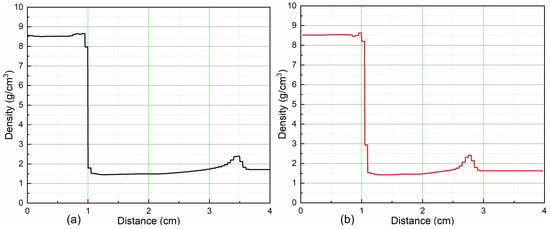
Figure 13.
(a) Density profile of JH-2 and (b) density profile of TNT. Density profiles can give evidence of the ignition of a material according to the ignition and growth model; ignition only starts if the density compression is greater than the critical compression threshold of the respective materials.
In the case of Figure 13a and Figure 13b, the related pressure contours show the detonation of both JH-2 and TNT explosives, manifested as shock waves, as illustrated in Figure 14a and Figure 14c. Standard International Organization for Standardization (ISO) containers used for transporting goods only have a wall thickness of 1.6 to 7 mm, which is insufficient to prevent detonation during a shaped charge jet attack. This was evident in our tests, where both TNT and JH-2 with 10 mm wall thickness containers (Figure 14a,c) underwent detonation. However, when 65 mm of protection was directly attached to the explosives (Table 1 and Figure 14d), neither TNT nor JH-2 detonated, successfully passing the AOP4526 test criterion that requires no full or partial detonation to pass energetic materials safety tests. Interestingly, with only 60 mm of separate protection (not directly attached) and a 20 mm steel cover, TNT only burned due to its inherent insensitivity. JH-2, however, detonated in this scenario (Figure 14b), likely due to a reflected shock wave caused by the witness cylinder.
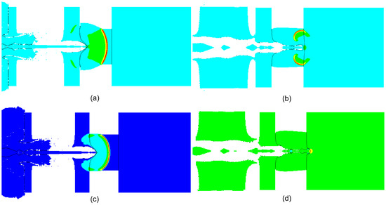
Figure 14.
(a,c) Shock waves from JH-2 and TNT detonations in 10 mm container walls, respectively. (b) The shock wave resulting from a reflected shock in JH-2. (d) The absence of detonation in TNT when provided with the same 60 mm of protection and a 20 mm energetic material cover as in (b).
In Figure 15a,b, the pressure development within JH-2 and TNT energetic materials, respectively, is depicted in relation to the corresponding figures in Figure 13. This pressure surpassed the Chapman–Jouguet (CJ) pressure of these materials, which is 296 kbar and 210 kbar in the case of JH-2 and TNT, respectively, leading to the initiation of a stable detonation in both cases for the 10 mm container wall thickness.

Figure 15.
(a) Pressure along the axis of explosives reached >296 kbar, the CJ pressure of JH-2, indicating stable detonation. (b) Similar behavior occurred for TNT, with its CJ pressure at 210 kbar.
In Figure 16a,b, the pressure profiles corresponding to the specific pressure contour shown in Figure 14d are presented, illustrating configurations incorporating TNT and JH-2 with steel wall protection of 65 mm. It is evident from these representations that despite traversing through the entirety of the energetic materials, the pressure generated remained below the Chapman–Jouguet pressure as the jet traversed through the explosives along its trajectory. Consequently, no detonation occurred in either TNT or JH-2 under these circumstances.
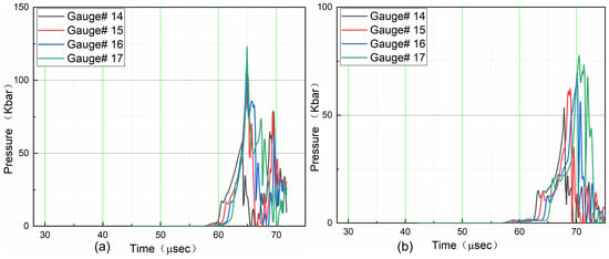
Figure 16.
(a) The pressure generated at the end of the JH-2 energetic material remained significantly below the Chapman–Jouguet (CJ) pressure of 295 kbar, indicating no detonation. (b) Similarly, the pressure within TNT remained considerably below its CJ pressure of 210 kbar.
The Lee–Tarver model was observed to accurately depict the physical behavior of TNT and JH-2 energetic materials. Notably, Figure 17 provides numerical predictions of crater formation in the steel base cylinder, complemented by authentic experimental crater images.
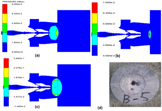
Figure 17.
Comparison between numerical and experimental evidence of detonation, where the simulation in (a–c) and experimental results in (d) all indicate that the crater formation could be accurately predicted by the effects of shock waves caused by detonation.
Hence, this investigation underscores the applicability of the ignition and growth (I&G) model for assessing the safety of various energetic materials within logistical configurations. This suggests that corresponding mitigation measures can be implemented based on the insights derived from this model.
6. Limitations of Lee–Tarver Model
Research demonstrates a significant correlation between the crystal structure of a material and its sensitivity to initiation [41]. Single crystals, characterized by their uniform atomic arrangement, exhibit high resistance to detonation and necessitate a substantial impact to trigger an explosion. This characteristic is generally true for homogeneous explosives, which are less sensitive to initiation compared to heterogeneous ones. Campbell et al. exemplified this by introducing imperfections such as grit and air bubbles into a homogeneous explosive, thereby markedly increasing its impact sensitivity [42]. Consequently, enhancing the uniformity of a heterogeneous explosive could reduce its sensitivity. This concept is well-supported by experimental evidence. For instance, in one of Campbell’s experiments, a high explosive was subjected to an initial weak shock of 3.9 GPa, followed by a stronger shock of 10 GPa. Remarkably, while the stronger shock alone would have detonated the material in its initial state, the subsequent exposure to the 10 GPa shock did not result in detonation after the initial weak shock. Campbell accurately hypothesized that the weak shock eradicated internal imperfections, thereby making the explosive more uniform and less sensitive. Similar findings were observed in his research with liquid energetic materials [43]. Therefore, in cases where the initial shock is weaker than the subsequent stronger shock, the phenomenon of shock desensitization occurs and is not accounted for in the Lee–Tarver model.
Similarly, when a detonation wave encounters a sharp corner during corner-turning experiments, it undergoes bending or diffraction. This diffraction process can significantly weaken the detonation in the vicinity of the corner. In extreme cases, the chemical reactions that sustain the detonation may not be able to keep up with the advancing shock wave. Consequently, the shock wave in this corner region can outpace the chemical reaction, leading to a scenario where the explosive is not ignited but rather rendered inert. This results in a “dead zone”, characterized by unreacted explosive material near the corner. Existing models, such as the Lee–Tarver model, which are based exclusively on the principles of ignition and reaction growth, fail to account for this desensitization effect. As a result, these models often predict higher pressures in the corner region than those observed in experimental data, as demonstrated by Tarver himself in LX-17 hockey puck experiments [44].
Nonetheless, to evaluate the safety of energetic materials, the desensitization observed due to both the corner-turning effect and shock loses significance due to the stipulations outlined in Standard Related Document 39 (SRD 39), also called AOP 39.1 [45]. This requirement mandates that the trajectory of a shot into a target be chosen such that the shaped charge jet traverses the greatest length of energetic material within the munition before encountering a turning corner. Empirical observations in the current study indicated that a significant portion of energetic material detonates within the initial 50 mm of penetration depth. Therefore, this limitation of the corner-turning effect loses its significance in the safety assessment of energetic materials. Moreover, the velocity gradient along the length of a shaped charge jet is such that the tip of the jet has the highest velocity, which decreases along the length of the jet. Therefore, according to the Held criteria, the jet energy levels and resultant shock strengths of the impacting jet are highest at its tip and gradually diminish towards its tail. Consequently, each preceding shock provided to the energetic material would be stronger than the subsequent shock in the case of a shaped charge jet. Therefore, the phenomenon of shock desensitization is not possible in the context of a shaped charge jet attack. Thus, one can reliably use the Lee–Tarver ignition and growth model for energetic material safety assessment in the case of shaped charge jet safety assessment procedures.
Several studies have sought to adapt the ignition and growth model to effectively capture the effects of desensitization. This adaptation is achieved by incorporating a desensitization parameter linked to the chemical reaction rate, whose evolution is controlled by an additional pressure-dependent desensitization rate law. This coupling mechanism adjusts the chemical reaction rate in regions where the explosive is deemed to have undergone desensitization. Furthermore, this approach accounts for the desensitization of energetic materials in instances of prior weak shock exposure. However, these studies are limited to specific geometrical problems and are not comprehensive enough to be integrated into commercially available software such as ANSYS AUTODYN or LS-DYNA, ANSYS 17.1.
7. Conclusions
RDX-based propellant formulations are indispensable components of rocket motors, forming the backbone of aerospace propulsion systems. However, assessing the safety of such energetic materials presents formidable challenges due to the diverse range of materials, associated costs, and the inherently destructive nature of accurately evaluating their safety and efficacy. Consequently, research in this field remains scarce. This study addressed these limitations by proposing and evaluating the applicability of the Lee–Tarver model for the energetic materials JH-2 and TNT. Through systematic study, application, and comparison with experimental results, the reliability and validity of this model were established. Utilizing AUTODYN, ANSYS 17.1 software, the Lee–Tarver model was applied, and the simulation results exhibited outstanding agreement with experimental data. The main findings of this research are summarized as follows:
- The experimental measurements of velocity and diameter of a JH-2 50 mm shaped charge jet, obtained using the flash X-ray technique, correlated closely with the velocity and diameter values predicted by AUTODYN simulations. In accordance with AOP 4526 standards, the assessment of energetic material safety necessitates a specific jet energy level of 120 mm3/µs2, which closely aligns with the characteristics of the JH-2 50 mm shaped charge utilized in this case, exhibiting a jet energy level of 119 mm3/µs2.
- The implemented modeling assessments successfully predicted experimental outcomes for both JH-2 and TNT across all trials. The strategic selection of shot lines, aligned with SRD39 safety assessment protocols, ensured traversal of the maximum length of both JH-2 and TNT in all trials. This approach mitigated potential overestimation by the Lee–Tarver model due to corner-turning effects, resulting in accurate predictions of all experimental outcomes.
- Both simulations and experimental investigations confirmed that 65 mm steel protection is sufficient for safely transporting RDX-based JH-2 formulations and TNT within a 10 mm storage box in logistical configurations, even against a shaped charge threat with a jet energy level equivalent to the standardized AOP4526 protocol. This finding underscores the effectiveness of this protective measure in mitigating potential transportation risks.
- The Lee–Tarver model proves instrumental in acquiring insightful knowledge regarding the safety of energetic materials. Its application not only mitigates the exorbitant costs and time associated with experimentation but also circumvents the destructive nature of conventional safety assessment tests. The informed knowledge gleaned from Lee–Tarver model simulations can serve a vital role in safeguarding lives, preserving costly equipment, and avoiding damage to civic infrastructure during potential lapses in energetic materials safety.
Author Contributions
Writing—original draft preparation, M.S.A.; supervision, funding acquisition, Z.H.; test technical support, X.Z. and Q.X.; conceptualization, Z.H. and X.Z.; methodology, M.S.A.; software, M.S.A.; validation, X.Z., Z.H. and B.M.; writing—review and editing, X.Z. and M.S.A. All authors have read and agreed to the published version of the manuscript.
Funding
This research was funded by the National Natural Science Foundation of China (grant nos. 11972196 and 11872214).
Data Availability Statement
The original contributions presented in the study are included in the article, further inquiries can be directed to the corresponding author.
Conflicts of Interest
The authors declare no conflicts of interest.
References
- Ringgenberg, O.; Mathieu, J. Commercial High Explosives. Chimia 2004, 58, 390. [Google Scholar] [CrossRef]
- Scanlon, T.J. Rewriting a Living Legend: Researching the 1917 Halifax Explosion. Int. J. Mass Emergencies Disasters 1997, 15, 147–178. [Google Scholar] [CrossRef]
- Hayles, D.R. How Safe Should Our Weapons Be; Air University Maxwell AFB AL: Montgomery, AL, USA, 2005; Available online: https://apps.dtic.mil/sti/pdfs/ADA477006.pdf (accessed on 10 April 2024).
- Spear, R.J.; Davis, L.M. An Australian Insensitive Munitions Policy: A Working Paper Prepared for the Australian Ordnance Council; Department of Defence, Defence Science and Technology Organisation, Materials Research Laboratory: Melbourne, Australia, 1989; Available online: https://apps.dtic.mil/sti/pdfs/ADA207950.pdf (accessed on 10 April 2024).
- Scherpelz, R.I.; Traub, R.J.; Droppo, J.G.; Parkhurst, M.A. Depleted Uranium Exposures to Personnel Following the Camp Doha Fire, Kuwait, July 1991; Pacific Northwest National Laboratory: Richland, WA, USA, 2000. Available online: https://www.gulflink.osd.mil/camp_doha_summary18may00.pdf (accessed on 10 April 2024).
- Gilani, I. Over 2000 Died in 49 Accidental Blasts over Past 20 Years. Ankara. 7 August 2020. Available online: https://www.aa.com.tr/en/world/over-2-000-died-in-49-accidental-blasts-over-past-20-years/1934294# (accessed on 25 March 2024).
- Duz, Z.N.; Geldi, M. Material Damage from Beirut Blast Surpasses $15 Billion. 12 August 2020. Available online: https://www.aa.com.tr/en/middle-east/material-damage-from-beirut-blast-surpasses-15-billion/1939886 (accessed on 25 March 2024).
- Li, J.; Li, F.; Xu, Z.; Yang, J.; Li, J. Research Progress of the Combustion Characteristics of Dust/Combustible Gas Hybrids. FirePhysChem 2024, in press. [Google Scholar] [CrossRef]
- Zeman, S.; Patil, V.B. Towards to Some Published Misconceptions about TNT and Ɛ-CL20. FirePhysChem 2024, in press. [Google Scholar] [CrossRef]
- Patil, V.B.; Zeman, S. Novel Approach for Preparation of the Energy-Safety Balanced Cocrystals of Attractive Nitramines via Coagglomeration. FirePhysChem 2024, in press. [Google Scholar] [CrossRef]
- Anniyappan, M.; Talawar, M.B.; Sinha, R.K.; Murthy, K.P.S. Review on Advanced Energetic Materials for Insensitive Munition Formulations. Combust. Explos. Shock Waves 2020, 56, 495–519. [Google Scholar] [CrossRef]
- Powell, I.J. Insensitive Munitions—Design Principles and Technology Developments. Propellants Explos. Pyrotech. 2016, 41, 409–413. [Google Scholar] [CrossRef]
- Bekhouche, S.; Trache, D.; Abdelaziz, A.; Chelouche, S.; Tarchoun, A.F. Towards Understanding the Effect of Temperature and Humidity on the Safety and Performance of Tracer Pyrotechnic Composition. FirePhysChem 2023, in press. [Google Scholar] [CrossRef]
- Michalchuk, A.A.L.; Rudić, S.; Pulham, C.R.; Morrison, C.A. Predicting the Impact Sensitivity of a Polymorphic High Explosive: The Curious Case of FOX-7. Chem. Commun. 2021, 57, 11213–11216. [Google Scholar] [CrossRef]
- AOP-39; NATO Standard, Policy for Introduction and Assessment of Insensitive Munitions. NATO: Brussels, Belgium, 2018; pp. 1–128. Available online: https://www.msiac.nato.int/sites/default/files/media/surveyVLCI/aop-39_edn_d_ver01_policy_for_introduction_and_assessment_of_insensitive_munitions_im_-_e.pdf (accessed on 20 March 2024).
- AOP-4382; NATO Standard, Slow Heating Test Procedurecs for Munitions. NATO: Brussels, Belgium, 2020; pp. 1–36. Available online: https://www.msiac.nato.int/sites/default/files/media/surveyVLCI/aop-4382_edn_a_ver01_slow_heating_test_procedures_for_munitions_-_e.pdf (accessed on 5 March 2024).
- AOP-4240; NATO Standard, Fast Heating Munition Test Procedures. NATO: Brussels, Belgium, 2018; pp. 1–46. Available online: https://www.msiac.nato.int/sites/default/files/media/surveyVLCI/aop-4240_edn_a_ver01_fast_heating_munition_test_procedures_-_e.pdf (accessed on 5 March 2024).
- AOP-4526; NATO Standard, Shaped Charge Jet Munitions Test Procedure. NATO: Brussels, Belgium, 2018; pp. 1–38. Available online: https://www.msiac.nato.int/sites/default/files/media/surveyVLCI/aop-4526_edn_a_ver01_shaped_charge_jet_munition_test_procedure_-_e_red.pdf (accessed on 4 March 2024).
- AOP-4396; NATO Standard, Sympathetic Reaction Test Procedures for Munitions. NATO: Brussels, Belgium, 2020; pp. 1–38. Available online: https://www.msiac.nato.int/sites/default/files/media/surveyVLCI/aop-4396_edn_a_ver_01_sympathetic_reaction_test_procedures_for_munitions_red.pdf (accessed on 4 March 2024).
- AOP-4496; NATO Standard, Fragment Impact Test Procedures for Munitions. NATO: Brussels, Belgium, 2019; pp. 1–30. Available online: https://www.msiac.nato.int/sites/default/files/media/surveyVLCI/aop-4496_edn_a_ver01_fragment_impact_test_procedures_for_munitions_-_e.pdf (accessed on 3 March 2024).
- AOP-4241; NATO Standard, Bullet Impact Munition Test Procedures. NATO: Brussels, Belgium, 2018; pp. 1–24. Available online: https://www.msiac.nato.int/sites/default/files/media/surveyVLCI/aop-4241_edn_a_ver01_bullet_impact_munition_test_procedures_-_e.pdf (accessed on 3 March 2024).
- Lee, E.L.; Tarver, C.M. Phenomenological Model of Shock Initiation in Heterogeneous Explosives. Phys. Fluids 1980, 23, 2362–2372. [Google Scholar] [CrossRef]
- Li, Y.; Yang, X.; Wen, Y.; Xiong, S.; Li, X. Determination of Lee-Tarver Model Parameters of JO-11C Explosive. Propellants Explos. Pyrotech. 2018, 43, 1032–1040. [Google Scholar] [CrossRef]
- Kury, J.W.; Breithaupt, R.D.; Tarver, C.M. Detonation Waves in Trinitrotoluene. Shock Waves 1999, 9, 227–237. [Google Scholar] [CrossRef]
- Clutter, J.K.; Belk, D. Simulation of Detonation Wave Interaction Using an Ignition and Growth Model. Shock Waves 2002, 12, 251–263. [Google Scholar] [CrossRef]
- Liu, R.; Han, Y.; Li, M.; Jiang, Z.; He, S. Shock Ignition and Growth of HMX-Based PBXs under Different Temperature Conditions. Cent. Eur. J. Energ. Mater. 2019, 16, 21–32. [Google Scholar] [CrossRef] [PubMed]
- Tarver, C.M.; Breithaupt, R.D.; Kury, J.W. Detonation Waves in Pentaerythritol Tetranitrate. J. Appl. Phys. 1997, 81, 7193–7202. [Google Scholar] [CrossRef]
- Liu, R.; Nie, J.; Jiao, Q. Study on Lee-Tarver Model Parameters of CL-20 Explosive Ink. In Advances in Intelligent Information Hiding and Multimedia Signal Processing, Proceedings of the 15th International Conference on IIH-MSP in Conjunction with the 12th International Conference on FITAT, Jilin, China, 18–20 July 2020; Springer: Berlin/Heidelberg, Germany, 2020; Volume 2, pp. 205–215. [Google Scholar]
- Hong, X.; Li, W.; Cheng, W.; Li, W.; Xu, H. Numerical Simulation of the Blast Wave of a Multilayer Composite Charge. Def. Technol. 2020, 16, 96–106. [Google Scholar] [CrossRef]
- Naya, T.; Kohga, M. Influences of Particle Size and Content of RDX on Burning Characteristics of RDX-Based Propellant. Aerosp. Sci. Technol. 2014, 32, 26–34. [Google Scholar] [CrossRef]
- Xiao, Q.; Huang, Z.; Zu, X.; Jia, X.; Zhu, Q.; Cai, W. Shaped Charge Penetration into High-and Ultrahigh-Strength Steel–Fiber Reactive Powder Concrete Targets. Def. Technol. 2020, 16, 217–224. [Google Scholar] [CrossRef]
- Zhu, Q.; Huang, Z.; Xiao, Q.; Zu, X.; Jia, X. Theoretical and Experimental Study of Shaped Charge Jet Penetration into High and Ultra-High Strength Concrete Targets. Int. J. Impact Eng. 2018, 122, 431–438. [Google Scholar] [CrossRef]
- Elshenawy, T.; Elbeih, A.; Li, Q.M. Influence of Target Strength on the Penetration Depth of Shaped Charge Jets into RHA Targets. Int. J. Mech. Sci. 2018, 136, 234–242. [Google Scholar] [CrossRef]
- Elshenawy, T.; Li, Q.M. Influences of Target Strength and Confinement on the Penetration Depth of an Oil Well Perforator. Int. J. Impact Eng. 2013, 54, 130–137. [Google Scholar] [CrossRef]
- Li, X.; Yang, Y.; Lv, S. A Numerical Study on the Disturbance of Explosive Reactive Armors to Jet Penetration. Def. Technol. 2014, 10, 66–75. [Google Scholar] [CrossRef]
- AUTODYN Theory Manual, Revision 4.0; Century Dynamics Inc.: Fort Worth, TX, USA, 1998.
- Bolstad, J.; Mandell, D. Calculation of Shaped Charge Jet Using MESA-2D and MESA-3D Hydrodynamic Codes; Los Alamos National Laboratory: Los Alamos, NM, USA, 1992. Available online: https://permalink.lanl.gov/object/tr?what=info:lanl-repo/lareport/LA-12274 (accessed on 3 April 2024).
- Downes, D.; Bouamoul, A.; Ensan, M.N. Numerical Simulation of the Shaped Charge; Defence Research and Development: Valcartier, QC, Canada, 2014. Available online: https://publications.gc.ca/collections/collection_2017/rddc-drdc/D69-37-2014-eng.pdf (accessed on 3 April 2024).
- Lee, E.L.; Hornig, H.C.; Kury, J.W. Adiabatic Expansion of High Explosive Detonation Products; University of California Radiation Lab: Livermore, CA, USA, 1968. Available online: https://www.osti.gov/servlets/purl/4783904 (accessed on 2 April 2024).
- Xin, C.L.; Xu, G.G.; Liu, K.Z. Application of Miller Energy Release Model for Aluminized Explosives. Chin. J. Energ. Mater. 2008, 16, 436–440. [Google Scholar]
- Campbell, A.W.; Travis, J.R. Shock Desensitization of PBX-9404 and Composition B-3. In 8th Symposium on Detonation; Los Alamos National Lab. (LANL): Albuquerque, NM, USA, 1985; pp. 1–13. [Google Scholar]
- Campbell, A.W.; Davis, W.C.; Ramsay, J.B.; Travis, J.R. Shock Initiation of Solid Explosives. Phys. Fluids 1961, 4, 511–521. [Google Scholar] [CrossRef]
- Campbell, A.W.; Davis, W.C.; Travis, J.R. Shock Initiation of Detonation in Liquid Explosives. In Proceedings of the Third Symposium on Detonation, Volume ACR, Princeton, NJ, USA, 26–28 September 1960; Volume 52, pp. 469–498. [Google Scholar]
- Tarver, C.M. Ignition and Growth Modeling of LX-17 Hockey Puck Experiments. Propellants Explos. Pyrotech. An Int. J. Deal. Sci. Technol. Asp. Energ. Mater. 2005, 30, 109–117. [Google Scholar] [CrossRef]
- AOP-39.1; Guidance on the Organisation, Conduct and Reporting of Full Scale Tests. North Atlantic Treaty Organization (NATO): Brussels, Belgium, 2022; pp. 1–44. Available online: https://standards.globalspec.com/std/14501537/aop-39-1 (accessed on 2 January 2024).
Disclaimer/Publisher’s Note: The statements, opinions and data contained in all publications are solely those of the individual author(s) and contributor(s) and not of MDPI and/or the editor(s). MDPI and/or the editor(s) disclaim responsibility for any injury to people or property resulting from any ideas, methods, instructions or products referred to in the content. |
© 2024 by the authors. Licensee MDPI, Basel, Switzerland. This article is an open access article distributed under the terms and conditions of the Creative Commons Attribution (CC BY) license (https://creativecommons.org/licenses/by/4.0/).