Article

AI-Based Anomaly Detection Techniques for Structural Fault Diagnosis Using Low-Sampling-Rate Vibration Data

1
Department of Aerospace Engineering, Inha University, 36, Gaetbeol-ro, Yeonsu-gu, Incheon 21999, Republic of Korea
2
Advanced SW Technology Team, Korea Aerospace Industries, 309, Teheran-ro, Gangnam-gu, Seoul 06151, Republic of Korea
*
Author to whom correspondence should be addressed.
Aerospace 2024, 11(7), 509; https://doi.org/10.3390/aerospace11070509
Submission received: 20 May 2024 / Revised: 14 June 2024 / Accepted: 20 June 2024 / Published: 24 June 2024
(This article belongs to the Special Issue Machine Learning for Aeronautics (2nd Edition))

Abstract

:
Rotorcrafts experience severe vibrations during operation. To ensure the safety of rotorcrafts, it is necessary to perform anomaly detection to detect small-scale structural faults in major components. To accurately detect small-scale faults before they grow to a fatal size, HR (high sampling rate) vibration data are required. However, to increase the efficiency of data storage media, only LR (low sampling rate) vibration data are generally collected during actual flight operation. Anomaly detection using only LR data can detect faults above a certain size, but may fail to detect small-scale faults. To address this problem, we propose an anomaly detection technique using the SR3 (Super-Resolution via Repeated Refinement) algorithm to upscale LR data to HR data, and then applying the LSTM-AE model. This technique is validated for two datasets (drone arm data, CWRU bearing data). First, the necessity for HR data is illustrated by showing that anomaly detection using LR data fails, and the upscaling performance of the SR3 algorithm is validated in the frequency and time domain. Finally, the anomaly detection for a structural fault diagnosis is performed for the upscaled data and the HR data using the LSTM-AE model. The quantitative evaluation of the Min–Max normalized reconstruction error distribution is performed through the MSE (Mean Square Error) value of the anomaly detection results. As a result, it is confirmed that the anomaly detection using upscaled test data can be performed as successfully as the anomaly detection using HR test data for both datasets by the proposed technique.

1. Introduction

A rotorcraft operates based on the lift generated by the high-speed rotating main rotor blades. Therefore, the major components of a rotorcraft are inevitably subject to various faults due to extreme loads and sustained high levels of vibration, and failing to detect these faults can lead to substantial economic losses and severe human casualties [1]. Moreover, as science and technology rapidly advance, faults in the major components of rotorcrafts are becoming more random, diverse, and uncertain [2]. In response, PHM (Prognostics and Health Management) systems, which ensure the safety and enhance the performance of rotorcrafts through reliable condition monitoring and fault prediction, are receiving increasing attention. In particular, PHM-related research is primarily focused on gearboxes, which consist of shafts, gears, and bearings, that continuously undergo cyclic fatigue due to the rotational movement of the power transmission system [3,4,5,6]. Additionally, many studies are actively being conducted on diagnosing the faults of major components and classifying fault cases using statistical features of data and machine learning techniques.
Altaf et al. [7] analyzed roller bearing vibration data to extract statistical features in both time and frequency domains, and based on these features, they classified faults using machine learning algorithms such as KNN (K-Nearest Neighbor) and a kernel linear discriminant analysis. The proposed method ensured low computational complexity and high accuracy. R.B.W. Heng et al. [8] proposed a method for diagnosing gearbox faults through the analysis of statistical features of vibration signals collected from Spectra Quest’s Gearbox prognostics simulator. After FFT (Fast Fourier Transform) of the vibration signal, statistical features such as the mean, median, minimum, maximum, kurtosis, and skewness were extracted from the frequency domain. These features were then inputted into an SVM (Support Vector Machine) classification model to categorize abnormal conditions. I. Aswani et al. [9] extracted statistical features from sound and vibration signals of shafts, rotors, and bearings to diagnose various fault conditions. They applied techniques such as decision trees, PCA (Principal Components Analysis), and ICA (Independent Component Analysis) to reduce data dimensionality, and classifiers such as SVM and PSVM (Probabilistic Support Vector Machine) to detect 12 different fault cases. To perform accurate anomaly detection using the statistical characteristics of multivariate time series data, it is necessary to extract features that accurately represent the characteristics of the data. This requires expert knowledge and significant time and effort. Additionally, when using machine learning classification algorithms such as KNN and SVM alone for anomaly detection, it is challenging to account for the time dependency in multivariate time series data. To address this challenge, it is necessary to construct hybrid models that combine algorithms capable of understanding time series characteristics with classification algorithms, or to improve the classification algorithms. So, recent research has focused on anomaly detection and prediction techniques using artificial neural networks based on unsupervised learning of time series data.
Anomaly detection and prediction models using artificial neural networks can be divided into prediction models, reconstruction models, and hybrid models. Prediction models consist of algorithms based on LSTM and GRU, which are excellent at identifying features in time series data [10,11,12]. In addition, there are several algorithms based on CNN [13] and Transformer [14]. These algorithms are trained to predict values for future points based on the training data. If the error between the predicted values and target values exceeds a predetermined threshold, it is considered an anomaly. Reconstruction-based models primarily consist of Auto-Encoders (AEs) [15,16,17]. Reconstruction-based models are trained to reconstruct the training data. When arbitrary data are inputted into the trained model, if the input data are similar to the training data, it results in low error, and if it is different, it results in high error. An anomaly is identified if this error exceeds a predetermined threshold. Hybrid models are models that combine a prediction model with a reconstruction model to obtain better time series representations [18].
Hundman et al. [19] used the LSTM algorithm to detect anomalies in numerous time series parameter data collected from satellites. Anomaly values were calculated by applying an EWMA (Exponentially Weighted Moving Average) to the errors between the predicted values and the target values. This approach improved prediction performance by approximating high anomaly values caused by rapidly changing values to the overall average. Ahmad et al. [20] compared anomaly detection results based on the LSTM-AE algorithm with results based on statistical features (skewness, kurtosis, mean, RMS, etc.) and classification algorithms using IMS (Intelligent Maintenance System) open-source bearing vibration data. The results showed that the LSTM-AE-based anomaly detection was more accurate through evaluation metrics such as Precision, Recall, and F1-Score. Cheng et al. [21] diagnosed normal and fault states in radar wave signals using ResNet-AE. ResNet-AE is an algorithm that models the AE structure using Residual blocks, which mitigate the vanishing gradient problem as deep learning models become deeper. ResNet-AE achieved the highest accuracy compared to other algorithms such as VAE (Variational AutoEncoder) and AE. Additionally, S. Lin et al. [22] proposed a VAE-LSTM, a hybrid of the generative neural network VAE and the LSTM algorithm, to detect anomalies in five open-source multivariate time series datasets. This approach demonstrated higher accuracy compared to anomaly detection results from VAE, ARMA, and similar methods. Xu et al. [23] proposed Anomaly-Trans, which uses the Transformer algorithm to detect anomalies based on the similarity between Series association (global time series features) and Prior association (local time series features). As a result of anomaly detection in open-source data, the proposed Anomaly-Trans resulted in the highest F1-Score among various algorithms such as LSTM-VAE and Omni Anomaly. Techniques for anomaly detection in multivariate time series data using unsupervised learning-based artificial neural networks do not require a data labeling task, which can save time and cost compared to methods that use statistical features. Additionally, these techniques can account for the time dependency of time series data, reflecting the irregular characteristics of the data.
According to the Nyquist theorem, vibration data should be sampled at least twice regarding the frequency of the highest frequency contained in the vibration to avoid loss of information and enable the accurate reconstruction of the original signal. Since smaller structural faults typically influence signals at higher frequencies, sampling at as high a frequency as possible enhances the sensitivity to the detection of small structural faults. Therefore, to accurately detect anomalies due to structural faults in rotorcraft using anomaly detection algorithms based on artificial neural networks, high-sampling-rate data are essential. However, collecting high-sampling-rate data throughout all operating times in all operational rotorcrafts is inefficient and unrealistic. Therefore, a method is needed that can detect small-scale faults using only the low-sampling-rate data typically stored in operational rotorcrafts, which ensures the safety of rotorcraft operation. In order to realize this, applications of upscaling techniques from LR data to HR data can be considered. P. K. Wong et al. [24] used IELSTM (Interaction Encoded LSTM) to upscale low-frequency multivariate time series data to high-frequency data. They demonstrated that the data upscaled through IELSTM more closely resemble the original high-frequency data compared to data upscaled through traditional machine learning and deep learning models such as Ridge, LASSO, and MLP. However, they only down-sampled the low-frequency data to three times less than the high-frequency data for model training and validation. K. Volodymyr et al. [25] also used a Transformer-based Zoom2Net to upscale low-resolution data stored at 20 Hz to 1000 Hz.
While studies have been conducted on anomaly detection using vibration data as well as upscaling techniques from LR data to HR data, research on enhancing the resolutions of anomaly detection by upscaling LR data has not been previously conducted. Therefore, in this paper, we propose a technique that uses the SR3 (Super-Resolution via Repeated Refinement) Diffusion model [26] to upscale LR data to HR data, and performs anomaly detection using the LSTM-AE algorithm [27]. By employing this technique, even if high-sampling-rate data are collected only from a minimum number of test rotorcrafts, accurate anomaly detection equivalent to the level of HR data can be achieved using only the LR data collected from all other operational rotorcrafts.
This paper is organized as follows: Section 2 explains the structure, training process, and inference process of the SR3 Diffusion model for upscaling LR data to HR data, as well as the anomaly detection algorithm, the LSTM-AE model, based on equations. Next, Section 3 describes the drone arm data and the open-source bearing data used for model training and validation. In Section 4, upscaled data are generated by applying the SR3 algorithm to upscale LR data in normal and fault states. Finally, the proposed technique is validated by comparing the anomaly detection results using the upscaled data and those using HR data.

2. Methodology

In this section, the anomaly detection technique using LR data that is proposed in this paper is described. Firstly, we explain the method to convert the data format from vibration data to an image, which is used to apply multivariate time series vibration data to the SR3 algorithm. Next, we describe the SR3 algorithm used to generate upscaled data from LR data, and finally the LSTM-AE algorithm for anomaly detection using upscaled data.

2.1. Converting Data Format from Vibration to Image

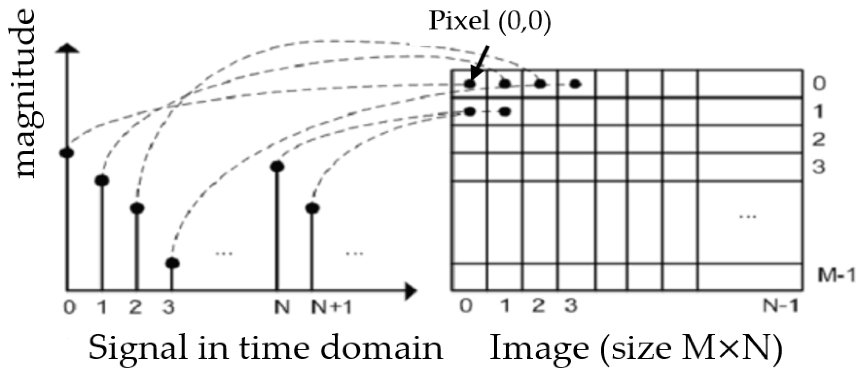
Before converting vibration data to image format, it is necessary to expand the LR data to the size of the HR data to be generated through the SR3 algorithm. LR data are expanded using cubic interpolation to generate cubic-interpolated data, as shown in Figure 1. Then, the cubic-interpolated data are normalized to values between 0 and 1 using the Min–Max scaler. The Min–Max scaler is defined as Equation (1), where x is the original data, x m i n is the minimum value of the x , x m a x is the maximum value of the x , and x n o r m is the normalized data. The normalized data are converted to the 2D image as shown in Figure 2. The data converted to image format are then inputted into the SR3 algorithm.
x n o r m = x x m i n x m a x x m i n ,

2.2. SR3 (Super-Resolution via Repeated Refinement)

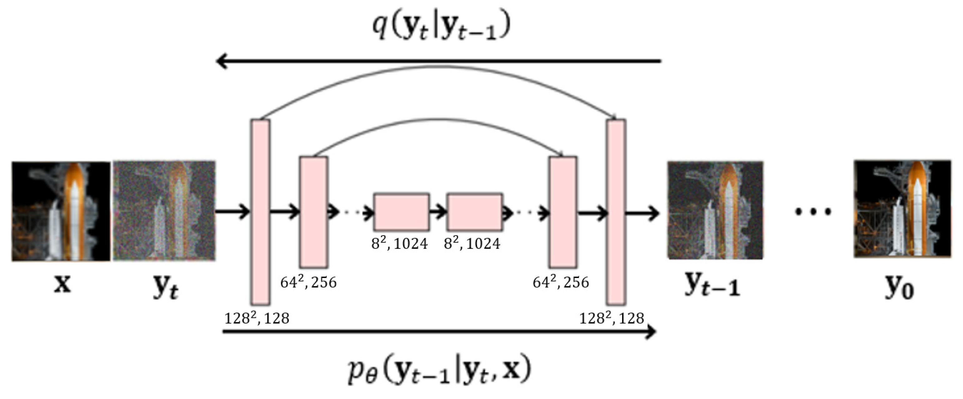
The data converted to image format are used for SR3 training. The training process is shown in Figure 3. The SR3 algorithm optimizes the denoising model f θ   ( x , y t , γ t ) by inputting the cubic-interpolated data x and the y t , which is HR data y 0 with added Gaussian noise ε . In addition to x and y t , γ t is also inputted into f θ . γ t is defined as Equation (2), where the scalar parameter α 1 : T (0 < α t < 1) is a hyper-parameter that determines the variance of the added noise ε at each iteration. The algorithm infers y t 1 through Equation (3) and, after T iterations, finally infers y 0 . When new x ^ is inputted into the trained algorithm, it outputs the high-resolution data y ^ 0 corresponding to the x ^ .
γ t = i = 1 t α i ,
y t 1 1 α t   ( y t 1 α t 1 γ t f θ   ( x , y t , γ t ) ) + 1 α t ε t .

2.3. LSTM-AE

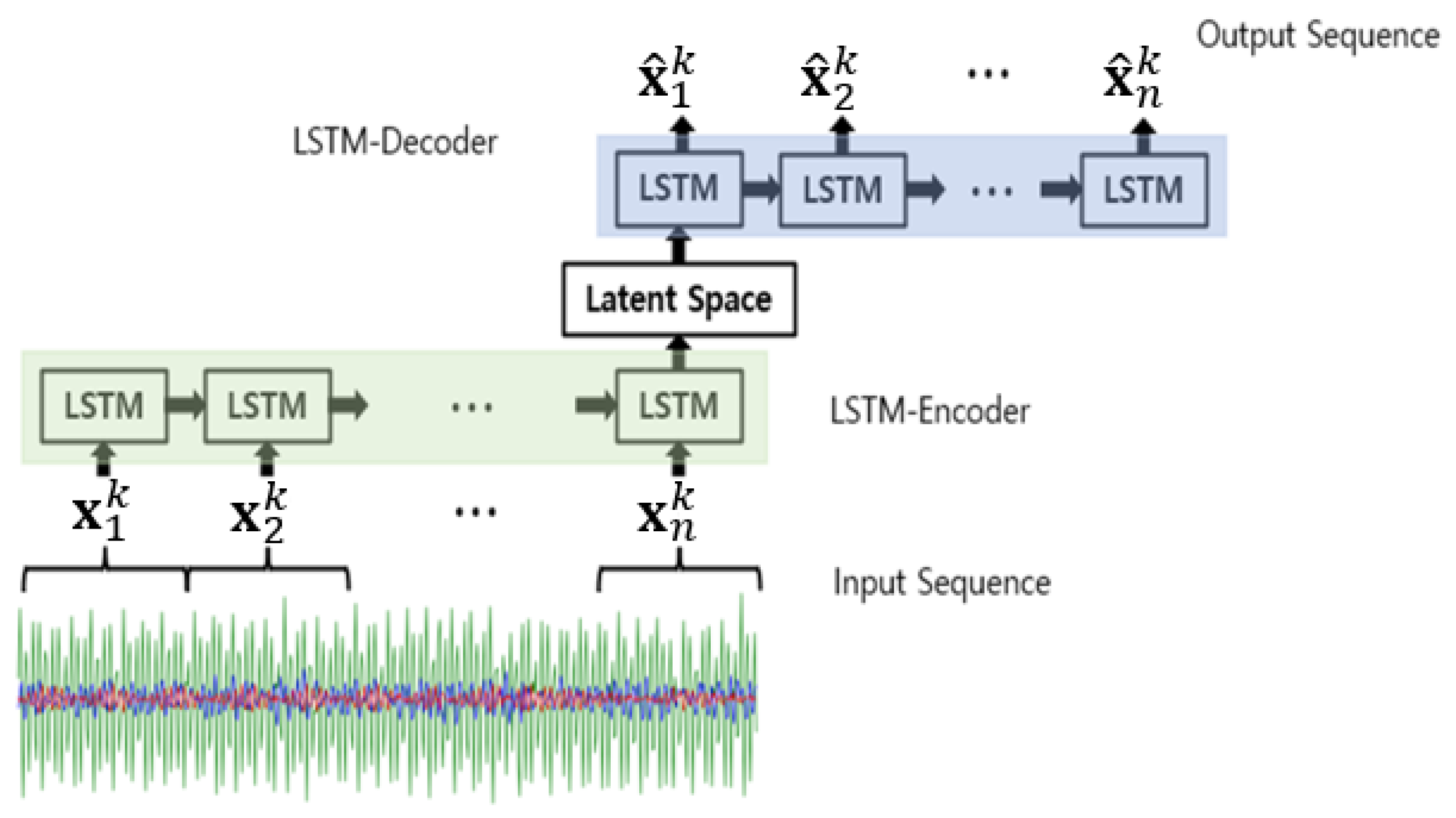
The LSTM-AE algorithm is applied to anomaly detection for the data generated through the SR3 algorithm. The structure of the LSTM-AE algorithm is depicted in Figure 4, and the training proceeds in the following steps. The data x are inputted into an encoder consisting of LSTM cells, and latent variables are stored in the latent space [29]. The stored latent variables are inputted into a decoder, which has the inverse structure of the encoder, resulting in the reconstructed value x ^ . The objective function is defined as Equation (4). The training data x i k represent multivariate time series data in a normal state, where i denotes the time step and k denotes the data dimension.
1 n i = 1 n   ( x i k x ^ i k ) 2 ,
The threshold is an essential component in algorithms for determining normal and fault states. In this paper, Chebyshev’s inequality [30] is used, which is one of the most commonly used methods for selecting a threshold. The anomaly e is the reconstruction error, calculated as the MSE between the reconstructed values x ^ and the training data x , as defined in Equation (5). The mean μ of the anomaly is calculated using Equation (6), and the standard deviation σ is calculated using Equation (7). The μ and the σ are used to calculate the threshold using Equation (8). Here, α is an arbitrary coefficient, and selected as the value 5, which shows the highest accuracy.
e = M S E   ( x , x ^ ) ,
μ = 1 n i = 1 n e i ,
σ = 1 n 1 i = 1 n   ( e i μ ) 2 ,
Threshold :   μ + α σ .
When arbitrary test data y are inputted into the trained LSTM-AE model, it produces the reconstructed value y ^ . The anomaly e is calculated as the difference between the reconstructed value y ^ and the original data y . If the value of e exceeds the predefined threshold, it is considered anomalous. Otherwise, it is considered normal.

2.4. Anomaly Detection Process for LR Data

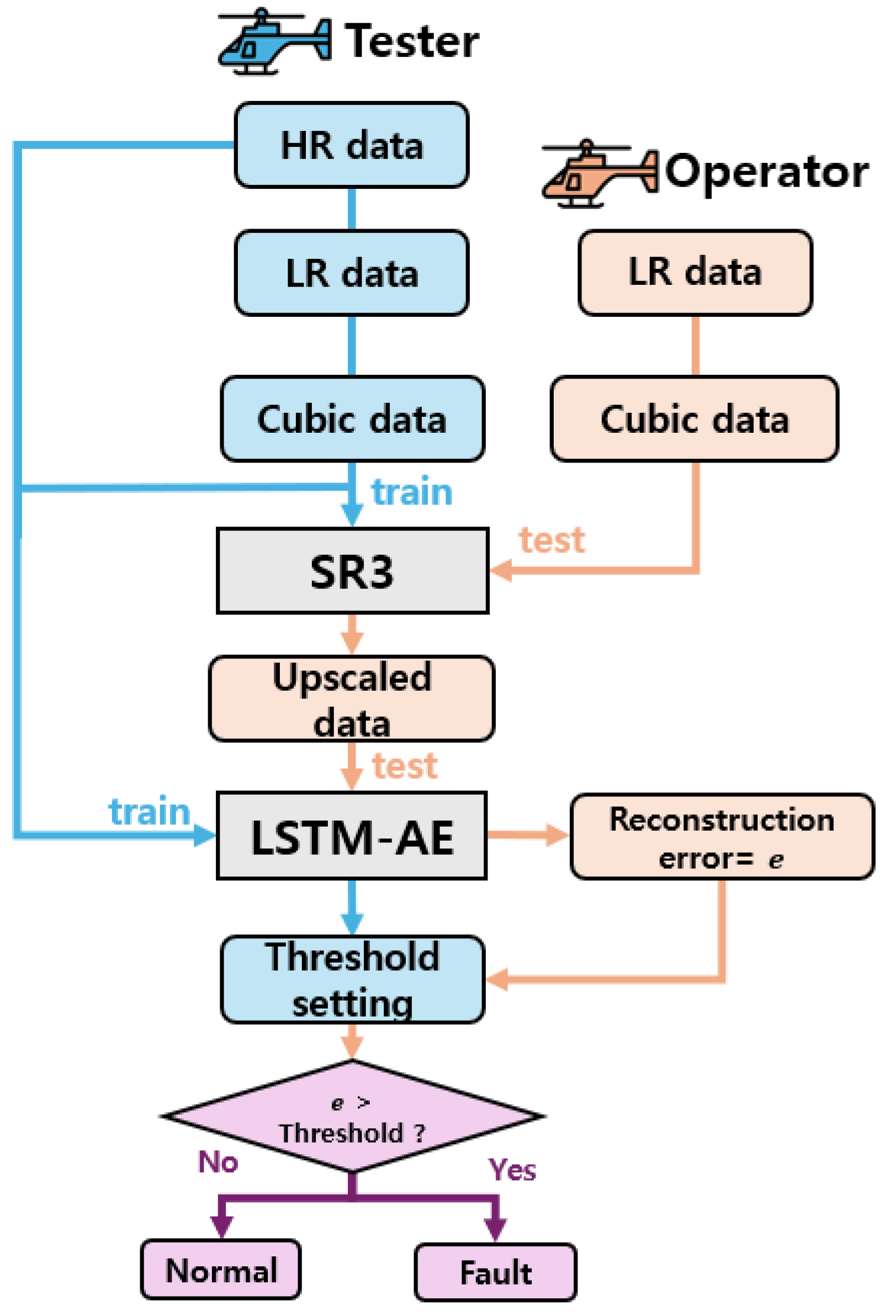
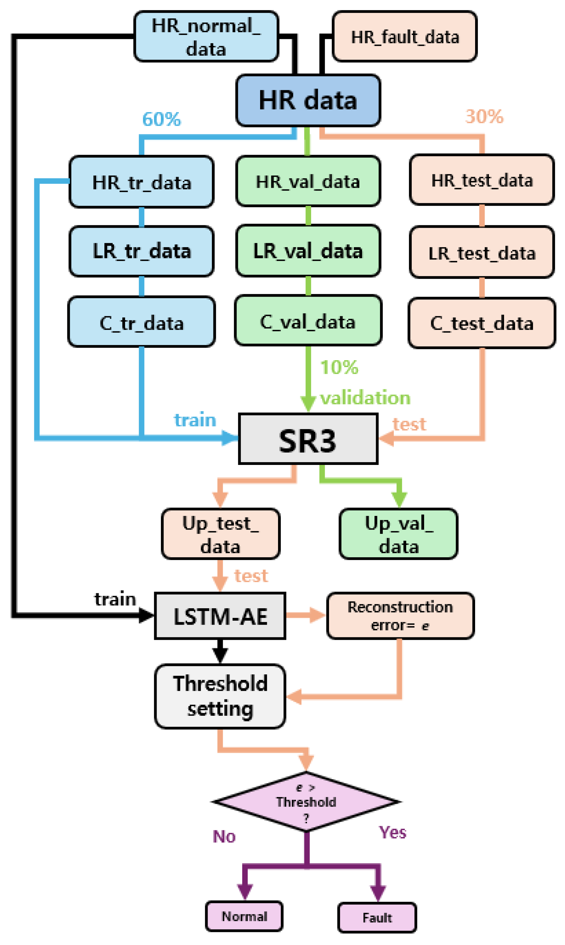
The process of performing anomaly detection using LR data obtained from actual rotorcrafts is depicted in Figure 5. Various types of HR data are collected from the tester, and cubic-interpolated data as well as LR data are generated for training of the SR3 model. Then, HR data and cubic-interpolated data are converted into image format. The SR3 model is trained using these data. Additionally, LSTM-AE is trained using HR data. The SR3 and LSTM-AE trained on the tester data are utilized for the Operator’s fault diagnosis. The Operator collects LR data during operation time, and the collected data are converted into cubic-interpolated data in image format. Then, the cubic-interpolated data are inputted into the trained SR3 to generate upscaled data. The generated upscaled data are then inputted into the trained LSTM-AE for the fault diagnosis.

3. Experimental Data Preparation for Anomaly Detection

To validate the anomaly detection technique using LR data described in Section 2, two datasets are used. The first dataset consists of vibration data collected by experiments from a custom-made drone arm. The second dataset is the CWRU (Case Western Reserve University) open-source bearing dataset [31]. Both datasets are collected as HR data and then converted into LR data.

3.1. Drone Arm Data

To collect vibration data from the drone arm, as shown in Figure 6, the arm of a DJI/F450 drone was 3D-printed and assembled, with the junction fixed to a test stand and a motor mounted on the opposite side. The MPU-6050 accelerometer was used to collect acceleration values for the X, Y, and Z axes at a sampling rate of 500 Hz. The drone arm can experience various types of faults due to the continuous vibration caused by the motor’s rotation, including structural damage from fatigue and a decrease in the clamping force of the bolts connecting the motor to the drone arm. In this study, we simulated the fault state by loosening the bolts between the motor and the drone arm to obtain fault data for anomaly detection.
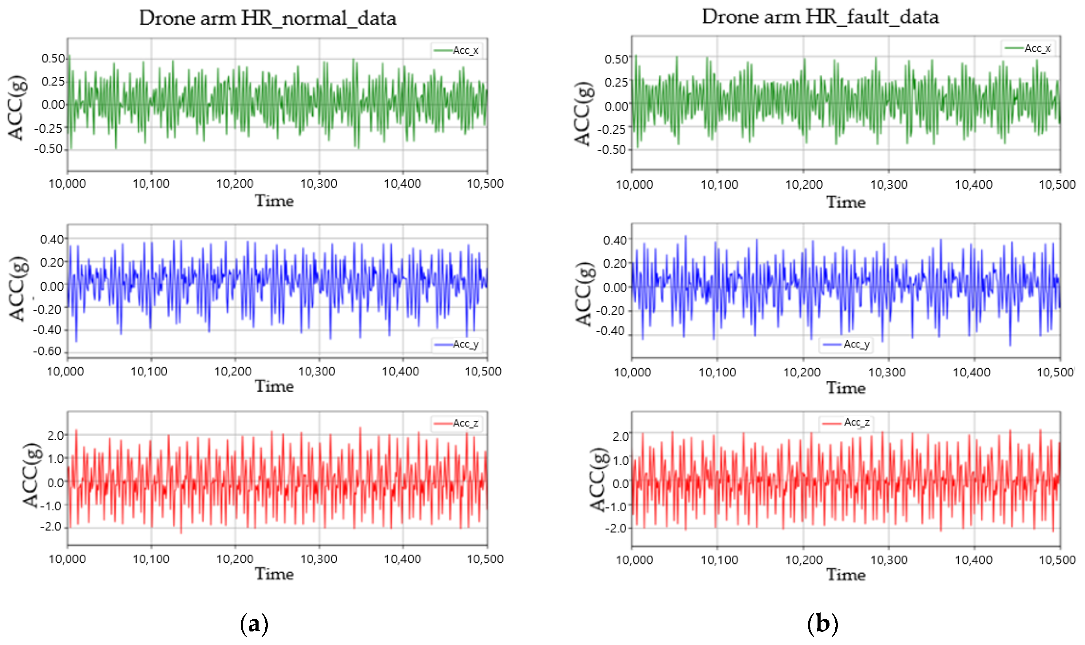
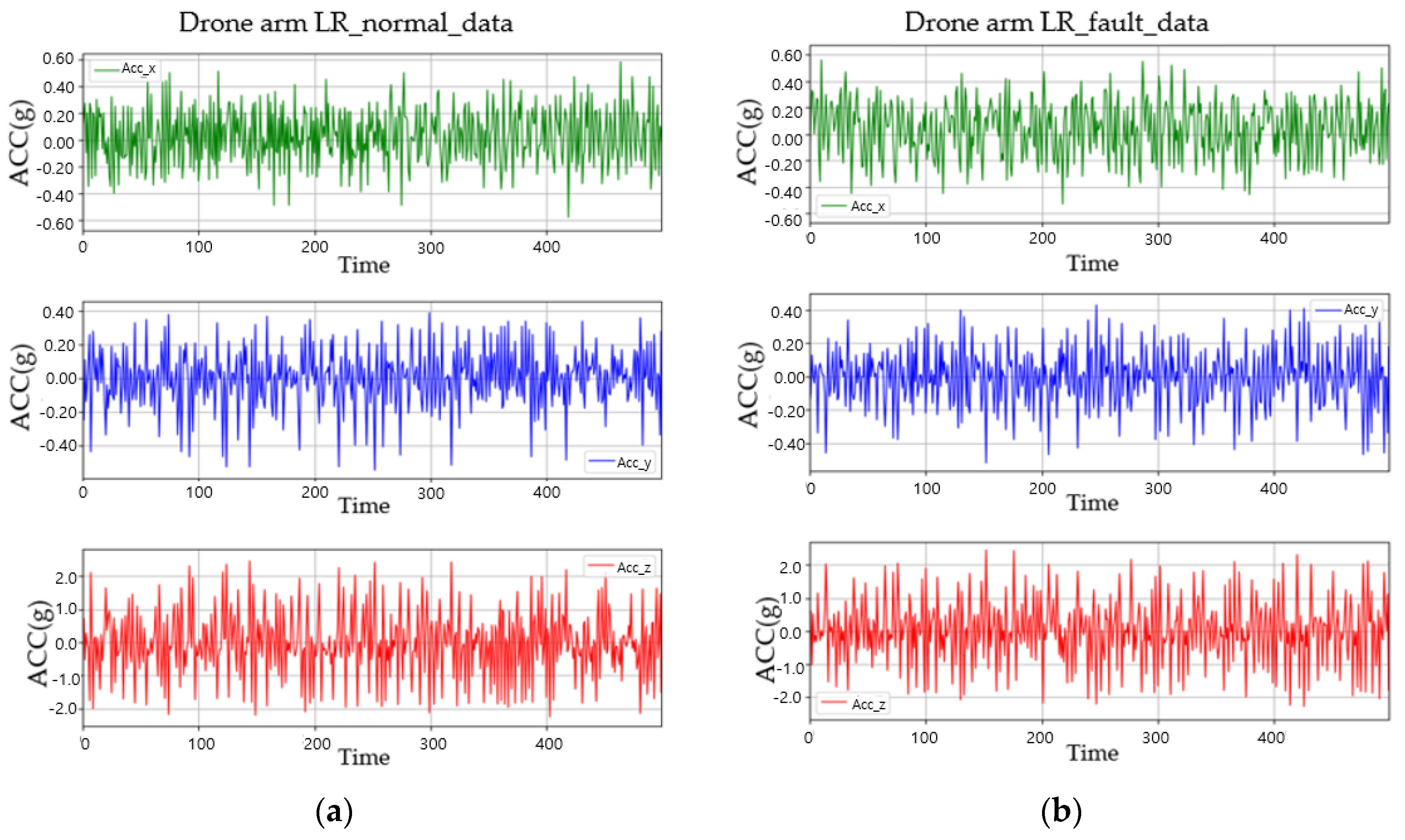
Figure 7a depicts vibration data in the normal state (HR normal data), while Figure 7b shows vibration data in the fault state (HR fault data). Every 60th value in the HR data was extracted to generate 8 Hz LR data from HR data, as depicted in Figure 8. A total of 8 Hz is the frequency at which a rotorcraft typically stores flight data.

3.2. CWRU Bearing Vibration Data

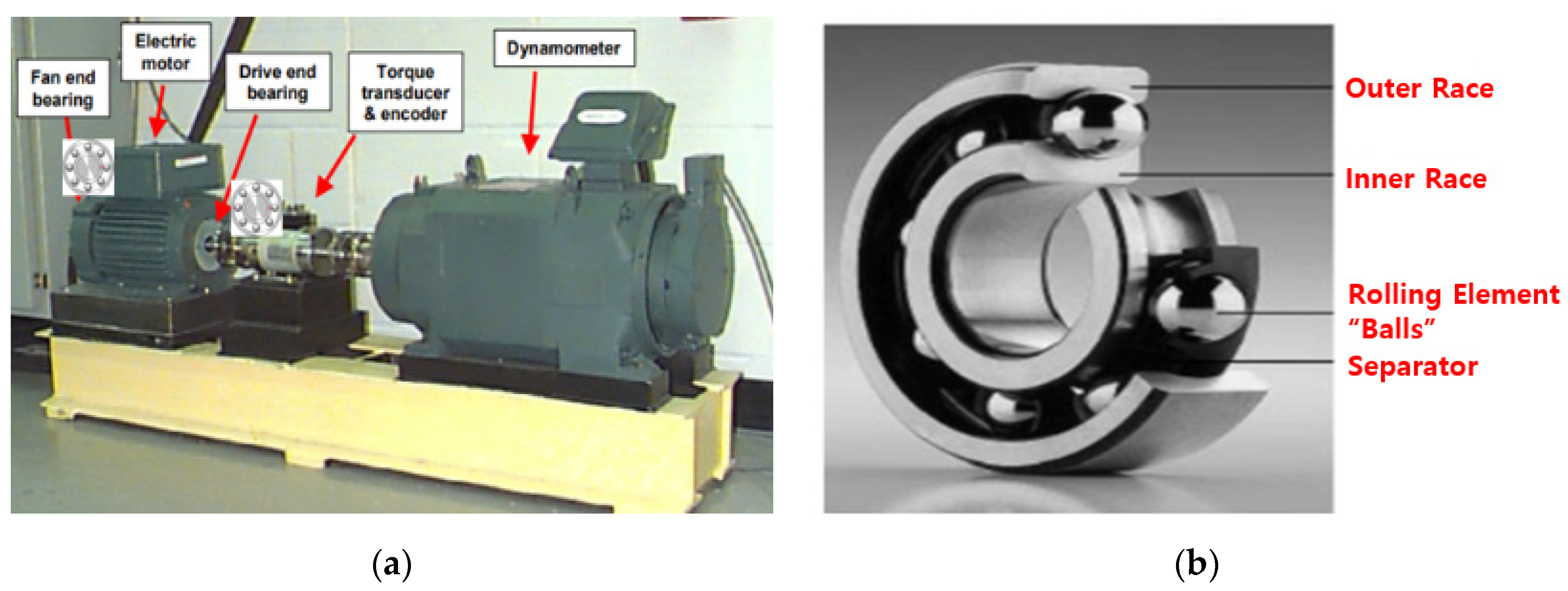
The CWRU bearing vibration dataset is an open-source dataset that measures vibration from the Fan end bearing (FE) and Drive end bearing (DE). The accelerometer was mounted in the 12 o’clock direction of the bearing housing to measure vibrations only in the direction perpendicular to the motor shaft. Vibration data at 12 kHz were collected from motors operating at constant speeds under loads of 0, 1, 2, and 3 HP. Figure 9 depicts the data collection environment and the structure of the bearing.
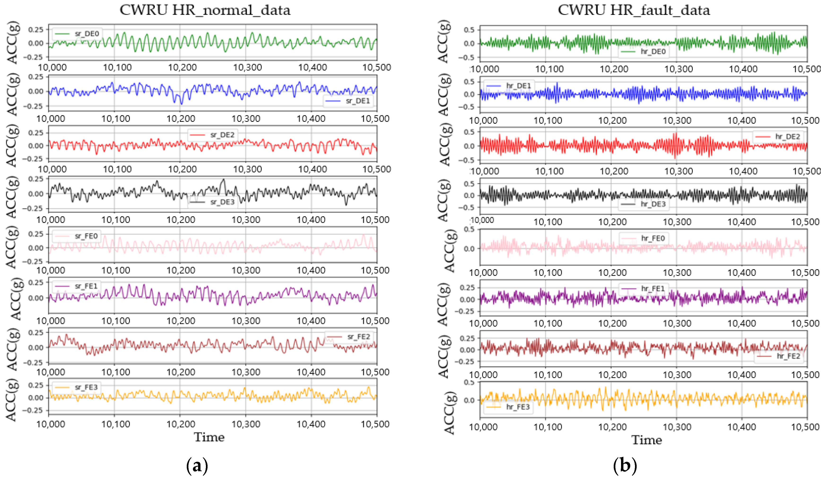
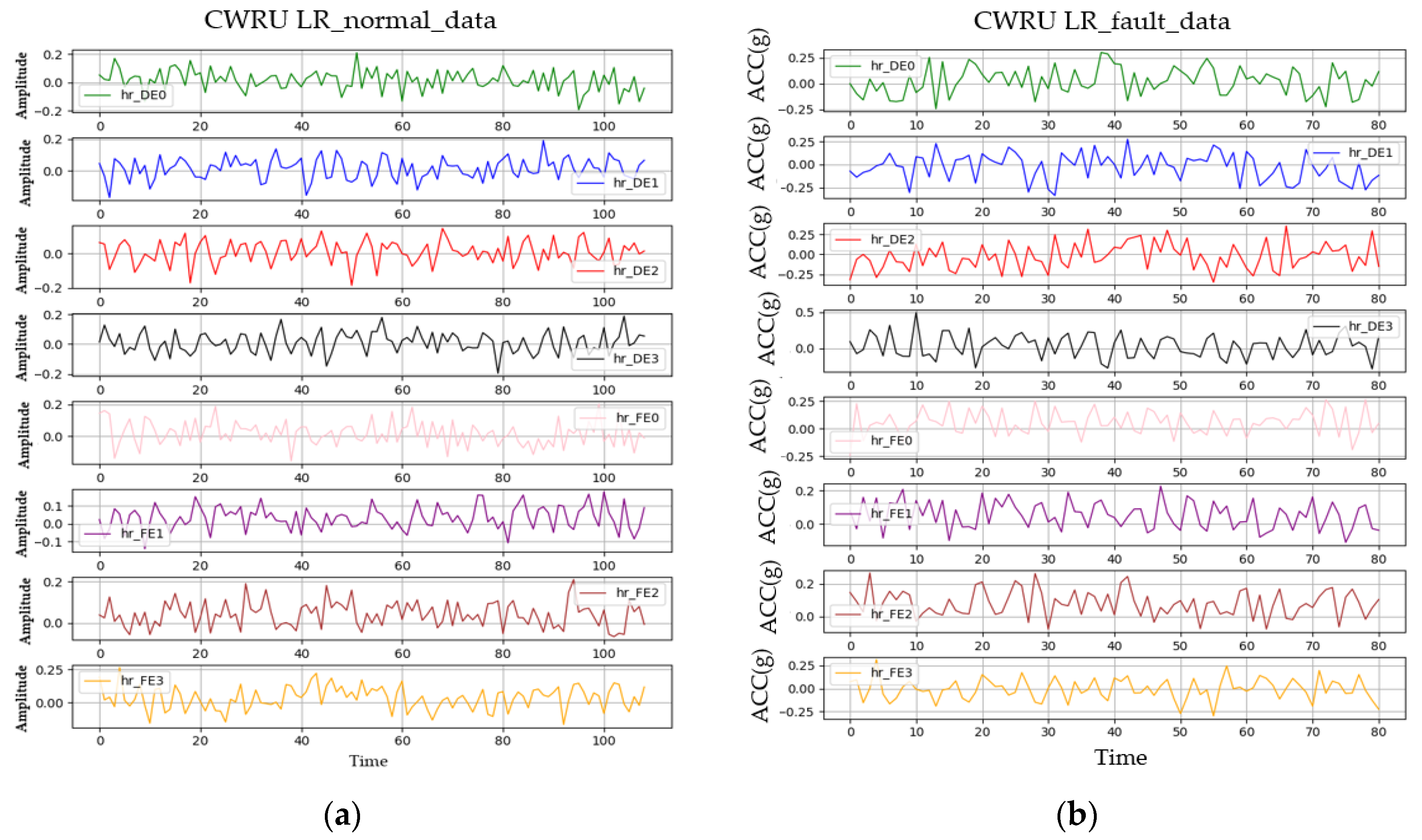
The obtained CWRU bearing vibration dataset consists of vibration data collected from the DE and FE at 0, 1, 2, and 3 HP loads, comprising a total of eight channels, including normal and fault states with a 0.007-inch ball defect. Figure 10 depicts HR normal data and HR fault data. The data were converted into 8 Hz LR data as shown in Figure 11, following the same method as the drone arm data.

4. Anomaly Detection Results

In this section, we perform anomaly detection using LR data with two datasets (drone arm and CWRU bearing) from Section 3 to verify the necessity of upscaling. Furthermore, we validate the techniques described in Section 2 using the same datasets. The validation procedure is depicted in Figure 12, and the datasets handled here are defined in Table 1. The detail hyper-parameters of the SR3 model used for data upscaling and the LSTM-AE used for anomaly detection are provided in Table 2 and Table 3, respectively.
ModelEpochsLearning RateBatchThreshold WeightChannels
SR3500,0000.000123CWRU: 8
Drone: 3

4.1. Effect of Sampling Rate for Anomaly Detection

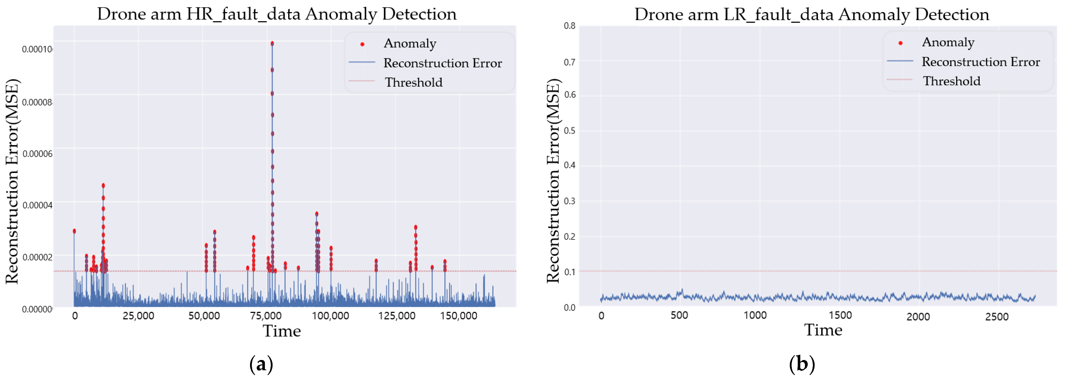
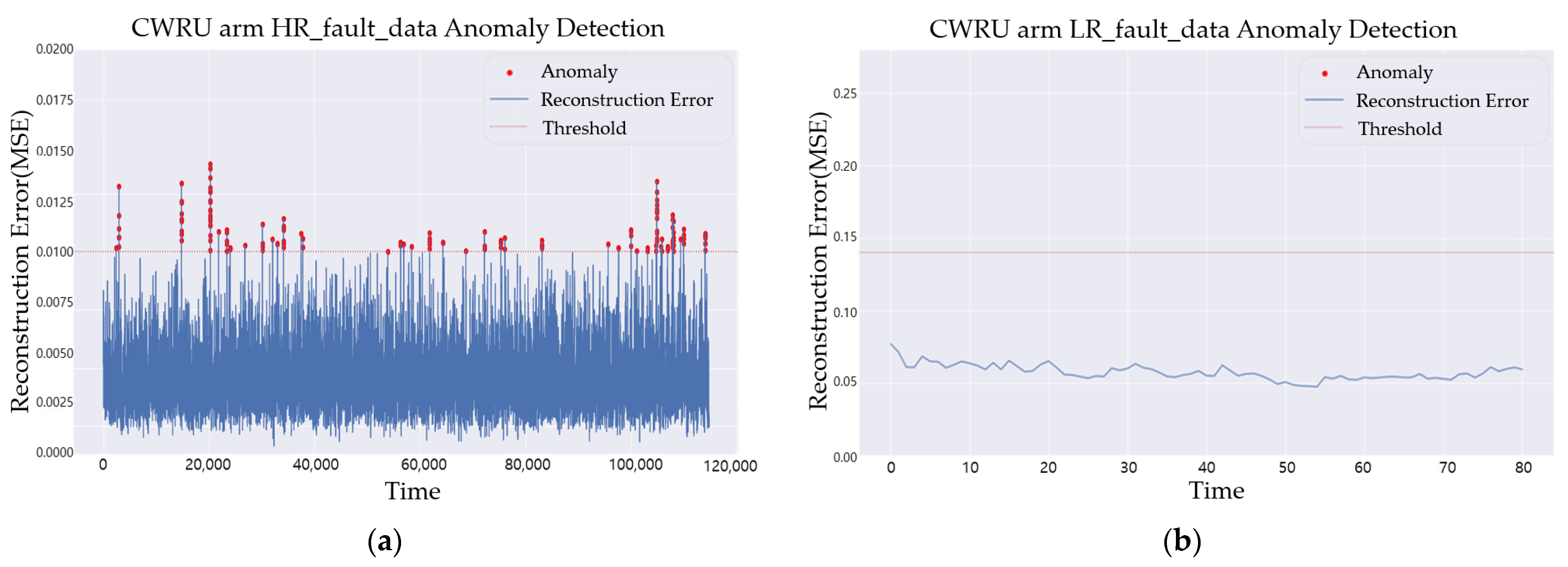
In this section, we examined the necessity of data upscaling by comparing anomaly detection results from LR data, cubic data, and HR data. Figure 13a shows the results of LSTM-AE training using HR_normal_data collected from the drone arm and testing it on HR_fault_data. The test results show that anomaly scores for the HR_fault_data are calculated to be above the threshold, indicating a fault. Figure 13b shows the results of LSTM-AE training using LR_normal_data extracted from HR_normal_data and testing it on LR_fault_data. The test results indicate that reconstruction errors for the LR_fault_data are calculated to be below the threshold, resulting in the failure to detect a fault. Figure 14 depicts the anomaly detection results for the CWRU bearing dataset. Similar to the anomaly detection results for the drone arm in Figure 13, proper anomaly detection was performed on HR_fault_data, while anomaly detection failed on LR_fault_data.
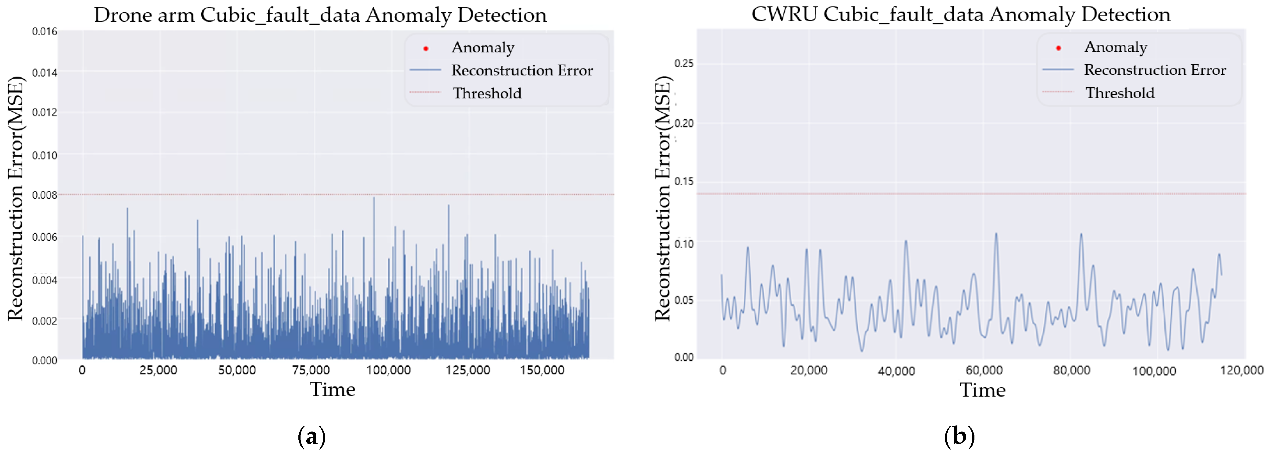
Figure 15 shows the results of anomaly detection performed on cubic-interpolated data. These results are obtained by training on cubic-interpolated normal data and testing on cubic-interpolated fault data. Figure 15a,b are the anomaly graphs about the drone arm and CWRU datasets, respectively. In both datasets, reconstruction errors for the fault data are calculated to be below the threshold, so they are determined to be in normal states.
From these results, it was confirmed that when diagnosing faults using LR data and cubic-interpolated data, the algorithm also calculated reconstruction errors even for the fault data to be below the threshold, which leads to a wrong decision to be in a normal state. This is because both LR data and cubic-interpolated data have lost some high-frequency information related to small-scale faults transmitted by the system due to the low sampling frequency. Therefore, anomaly detection using LR data or linear/cubic-interpolated data is unreliable for small-scale faults due to loss of high-frequency information, which indicates that upscaling to HR data is essential.

4.2. SR3 Algorithm Validation

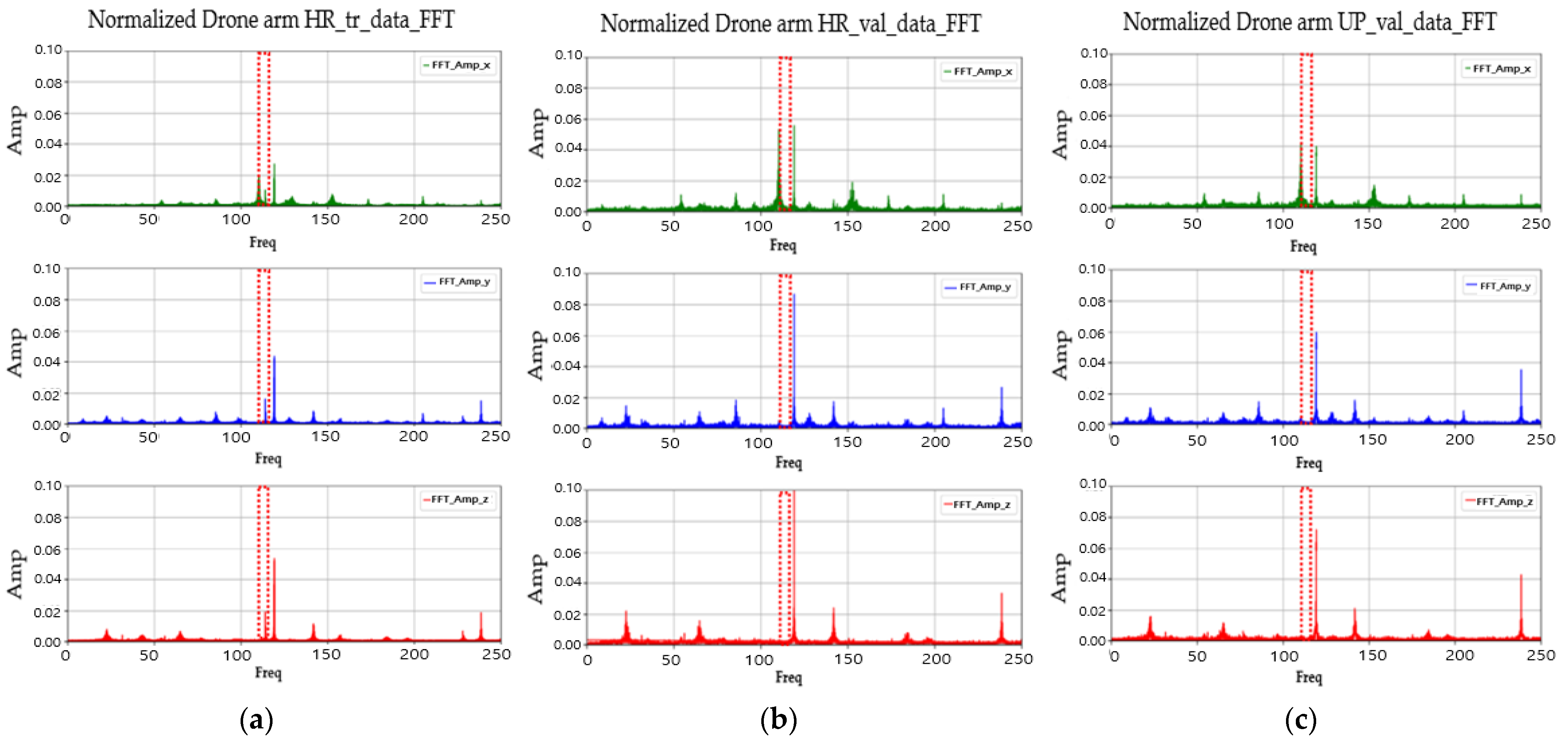
If the upscaled data generated by the SR3 algorithm are overfitted to the HR_tr_data used for training, the upscaled test data may follow the characteristics of the HR training data rather than the HR test data during the anomaly detection process. This may affect the anomaly detection results using the upscaled data and implies that there may be issues with the reproducibility of the proposed method when applied to different datasets. For the SR3 algorithm validation and ensuring the reproducibility of the proposed method, similarity comparisons were conducted in both the frequency domain and the time domain. The HR_tr_data, HR_val_data, and Up_val_data were transformed into frequency domains using FFT, and the Dynamic Time Warping (DTW) distance was calculated. The frequencies derived from each data and DTW result were then analyzed to determine the presence of overfitting.
Figure 16 depicts graphs for the frequency domain data of the drone arm HR_tr_data, HR_val_data, and Up_val_data, respectively. As shown in the FFT graphs of the three data types, it was observed that vibration components at 113 Hz were detected in the HR_tr_data for the X, Y, and Z axes. However, no vibration components were detected at 113 Hz in the HR_val_data and Up_val_data. To numerically evaluate this, the MSE for the amplitude values in the frequency domain was calculated. The MSE values between Up_val_data and HR_tr_data were larger than those between Up_val_data and HR_val_data on all three axes. Figure 17 shows the HR_tr_data, HR_val_data, and UP_val_data in the time domain. The DTW distance between UP_val_data and HR_val_data was approximately 11, while the DTW between UP_val_data and HR_tr_data was about 41 across all three axes. This indicates that Up_val_data is not overfitted to HR_tr_data, and confirms that it successfully restores the information of HR_val_data.
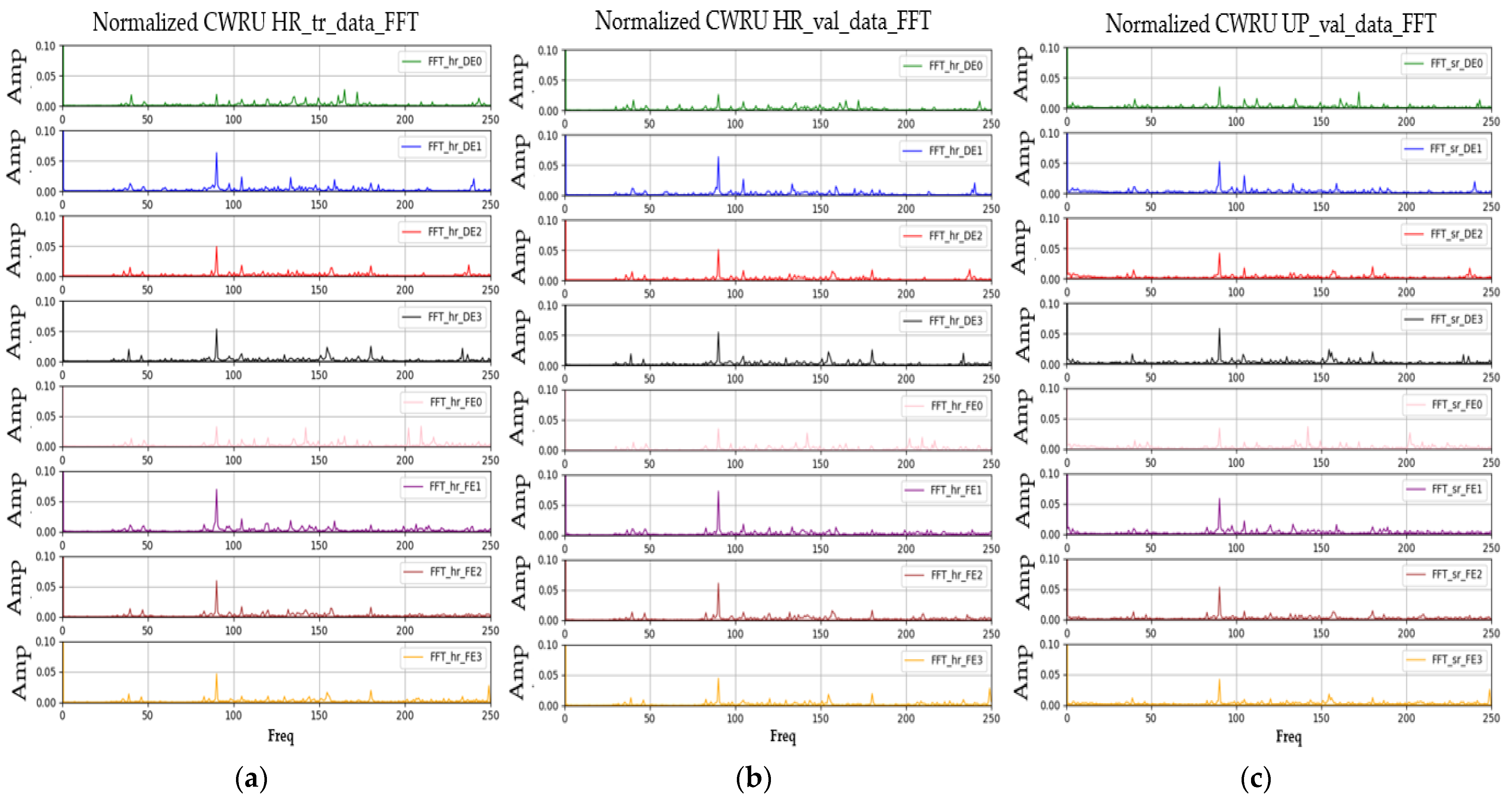
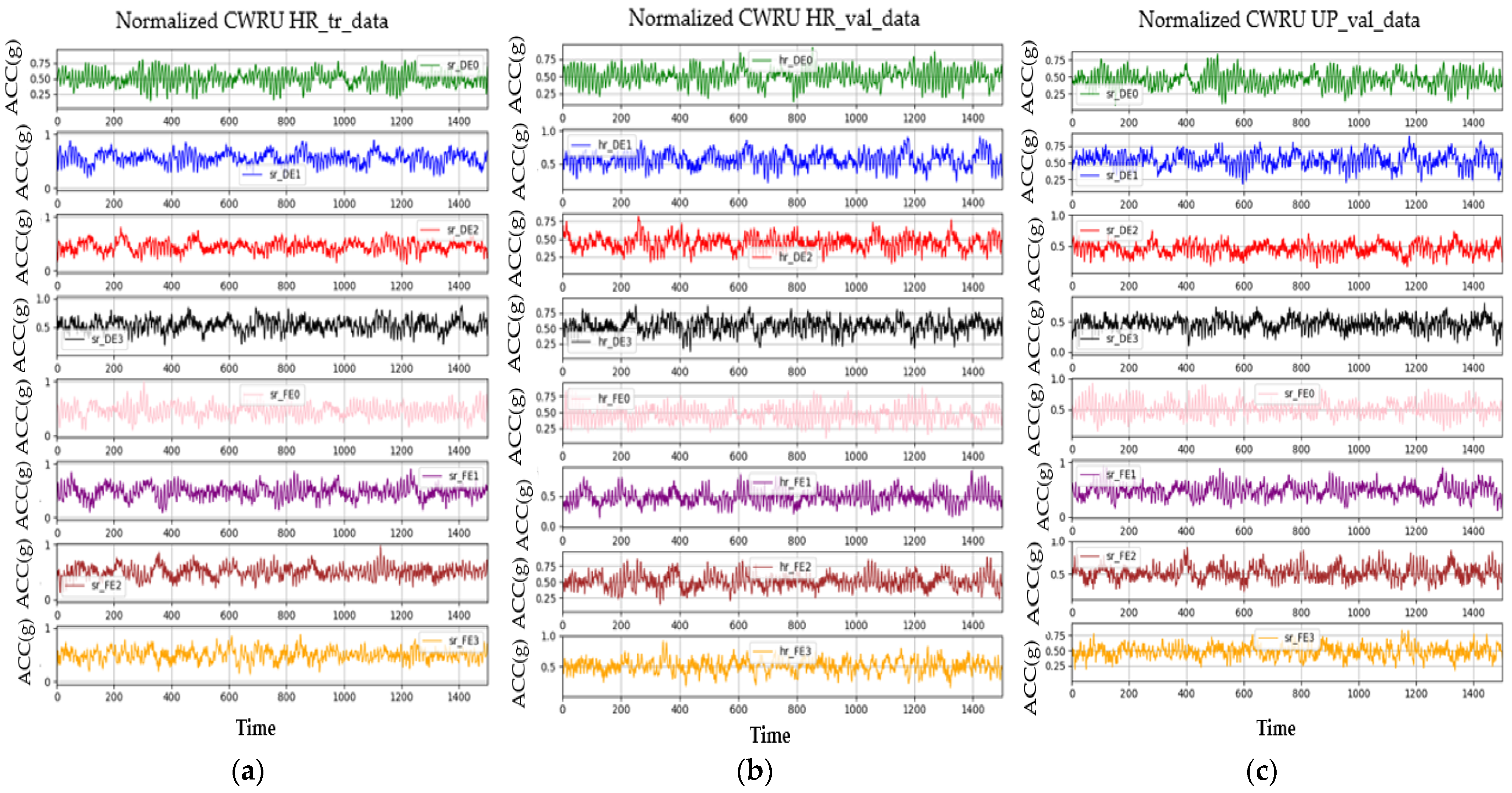
Similarly to the drone arm data, validation was performed on the Up_val_data for the CWRU bearing data. Figure 18 shows the results of FFTs on the CWRU HR_tr_data, HR_val_data, and Up_val_data, respectively. The MSE values between Up_val_data and HR_tr_data in the frequency domain were larger than those between Up_val_data and HR_val_data for all components except for two components with slight differences. Figure 19 shows the HR_tr_data, HR_val_data, and UP_val_data in the time domain, respectively. Table 4 presents the results of comparing the DTW distance between Up_val_data and HR_tr_data/HR_val_data. It is confirmed that Up_val_data are more closely approximated to HR_val_data than HR_tr_data for all parameters.

4.3. Anomaly Detection Using Upscaled Data

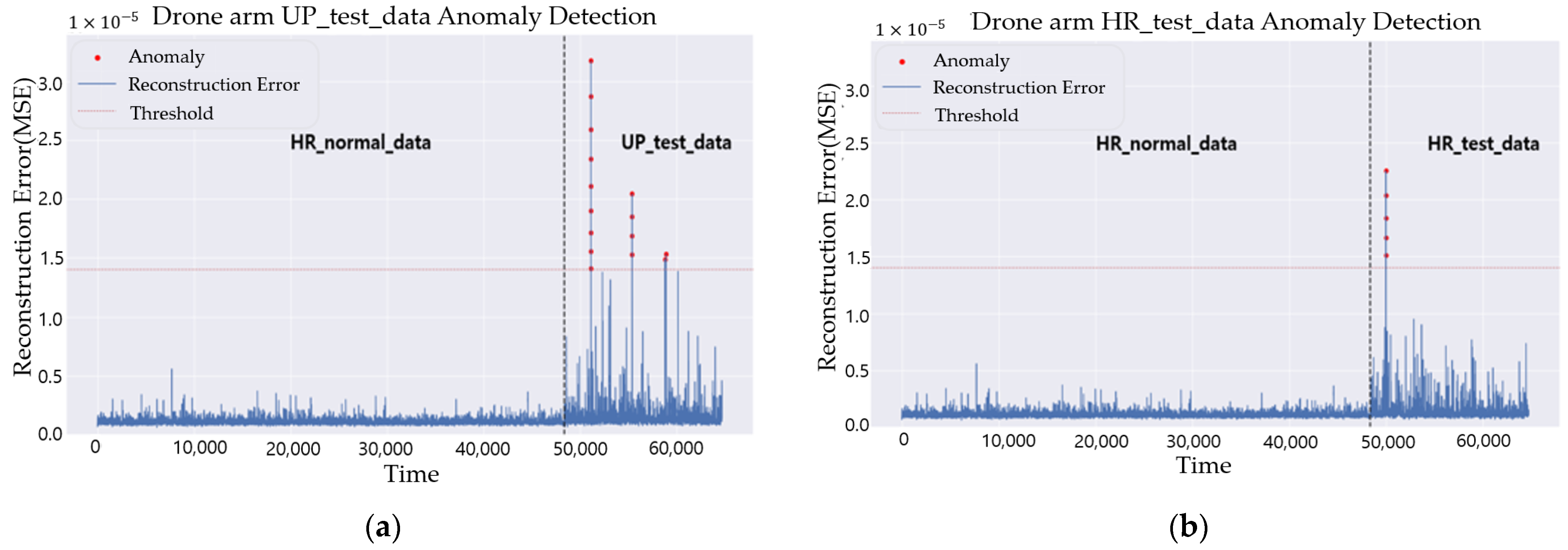
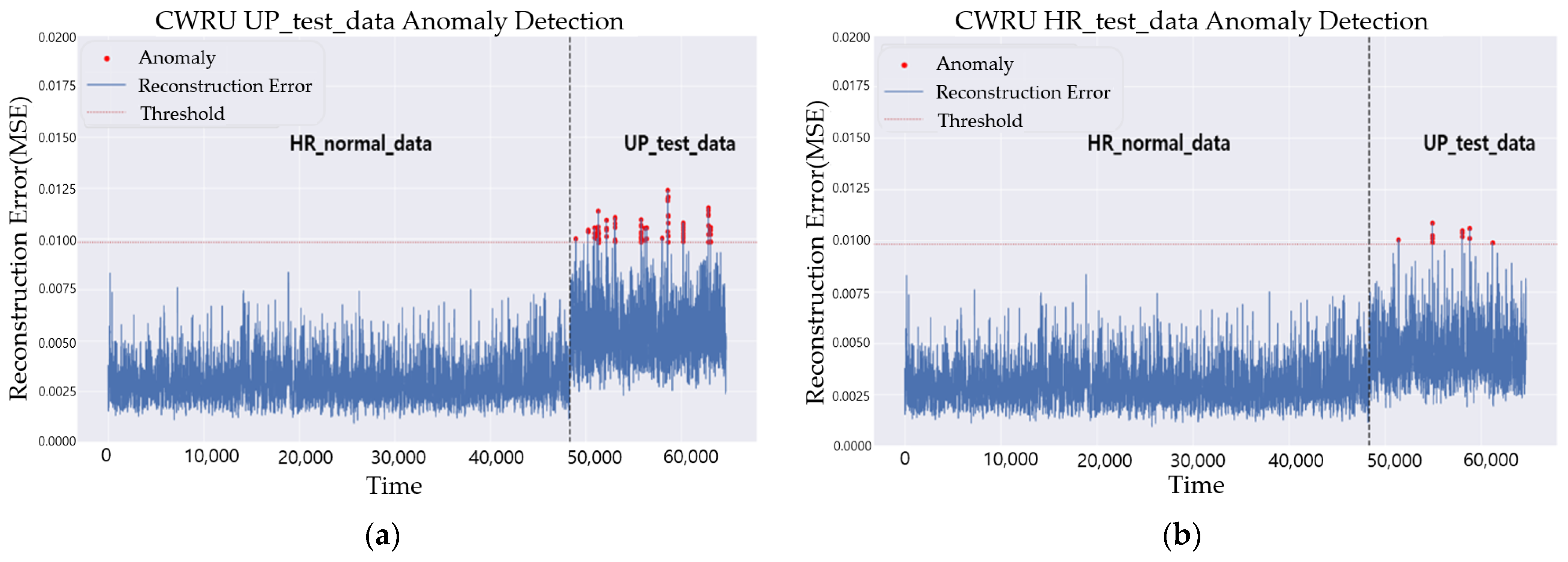
To validate the anomaly detection using Up_test_data obtained from the SR3 algorithm, the results of testing both Up_test_data and HR_test_data were compared using the LSTM-AE model trained on HR_normal_data. To simulate a scenario where a failure occurs in a structure while in a normal state, the test data were composed by concatenating HR_normal_data and UP_test_data/HR_test_data. Figure 20 and Figure 21 show the validation results for the drone arm and CWRU bearing data, respectively, with (a) displaying the anomaly detection results for (HR_normal_data, Up_test_data) and (b) displaying the results for (HR_normal_data, HR_test_data). In each graph, the left part of the black dotted line represents the results of the anomaly detection of the HR_normal_data, which is considered as a normal state, and the right part indicates the results of the anomaly detection of the fault data (Up_test_data or HR_test_data), which is considered as a fault state. It is confirmed that the anomaly detection using Up_test_data can be performed as successfully as the anomaly detection using HR_ test_data for both datasets.
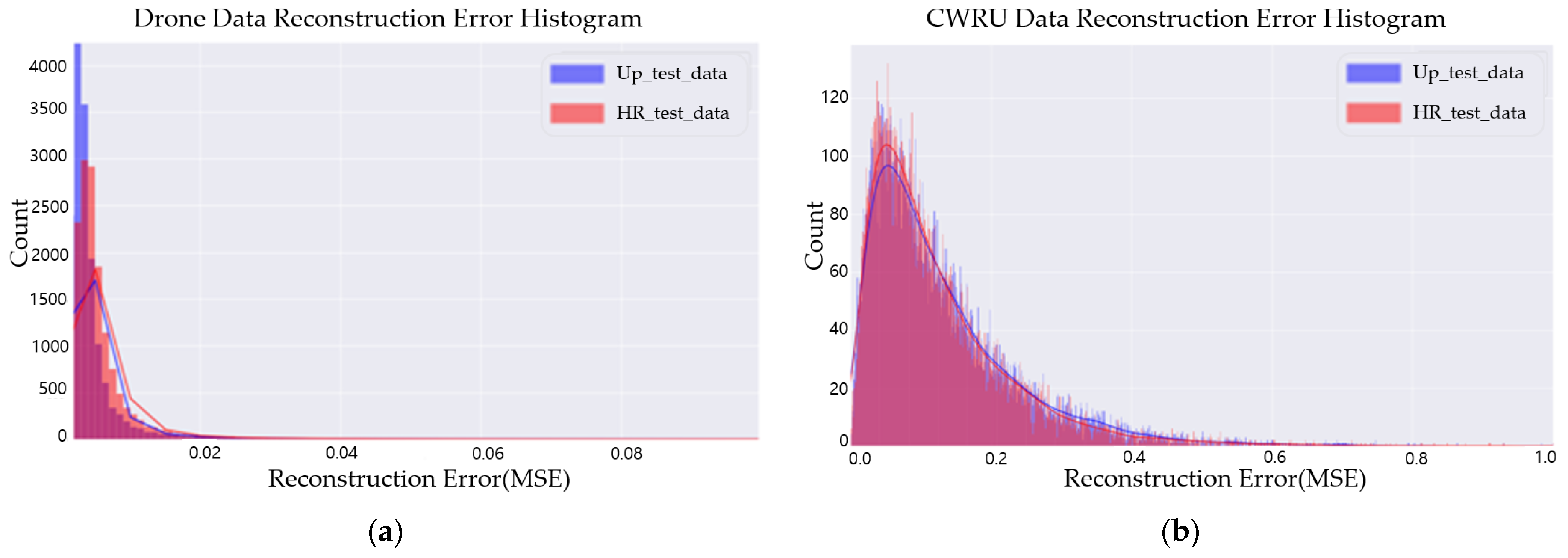
Figure 22 depicts histograms and kernel density estimation curves for anomaly scores in Up_test_data and HR_test_data; (a) and (b) corresponds to drone arm and CWRU bearing data, respectively. In the graphs, the x-axis represents the scores of the anomalies, and the y-axis represents the count of the same anomaly scores. This shows that the distribution of anomaly scores is similar for both Up_test_data and HR_test_data. According to the results of calculating the MSE to numerically evaluate the differences between the anomalies’ distributions of Up_test_data and HR_test_data, a slight error of 0.0004 occurred in the drome arm, and an error of 0.02 occurred in the CWRU. Before calculating the MSE, the anomalies’ distribution was normalized to have values between 0 and 1.

5. Conclusions

This paper proposed an anomaly detection technique for a structural fault diagnosis using LR data to ensure the efficient operation and safety of rotorcraft. This is a technique that applies LR data to the SR3 algorithm to generate upscaled data in the high-frequency band, which are then inputted into the LSTM-AE algorithm to perform anomaly detection. To validate this technique, drone arm and CWRU bearing data were acquired, and it was confirmed that anomaly detection cannot be properly performed with only LR data as is. And then, a data analysis in the frequency domain and the time domain was conducted to validate the reliability of the upscaled data generated by the SR3 algorithm. Finally, the anomaly detection results of the upscaled data were compared with those of the HR data, confirming that anomaly detection was performed successfully with high accuracy.
When applying the anomaly detection technique using LR data to rotorcraft, the SR3 and LSTM-AE algorithms can be trained using HR data collected from tester rotorcrafts. And then, only LR data collected from operational rotorcrafts are used to obtain upscaled data through the SR3 algorithm, which is then used to perform anomaly detection using the LSTM-AE algorithm. However, for accurate anomaly detection using the proposed technique, it is essential to collect enough high-frequency band data from various cases using tester rotorcrafts. If only the required data are available, this approach enables precise and cost-effective anomaly detection at the level of HR data obtained from tester rotorcrafts, using only LR data basically collected from operational rotorcrafts, without the need for additional equipment for HR data collection on operational rotorcrafts.

Supplementary Materials

The following supporting information can be downloaded at: https://www.mdpi.com/article/10.3390/aerospace11070509/s1, the source codes for this research.

Author Contributions

Conceptualization, J.-H.K.; Methodology, Y.J.; Software, Y.J.; Validation, Y.J. and E.-G.P.; Investigation, E.-G.P.; Resources, S.-H.J.; Data curation, S.-H.J.; Writing—original draft, Y.J.; Writing—review & editing, E.-G.P. and J.-H.K.; Supervision, J.-H.K.; Project administration, J.-H.K.; Funding acquisition, S.-H.J. All authors have read and agreed to the published version of the manuscript.

Funding

This research was conducted in 2022 with the support of the Korea Research Institute for defense Technology planning and advancement with funding from the government (the Defense Acquisition Program Administration) (KRIT-CT-22-081, Weapon System CBM+ Research Center).

Data Availability Statement

CWRU bearing data site is cited in reference no. [31] and Supplementary Materials.

Acknowledgments

The authors would like to acknowledge the support of the Korea Aerospace Industries.

Conflicts of Interest

Author Seon-Ho Jeong employed by the Korea Aerospace Industries. The remaining authors declare that the research was conducted in the absence of any commercial or financial relationships that could be construed as a potential conflict of interest.

References

  1. Carcel, C.R.; Starr, A.; Ottewill, J.R.; Jaramillo, V.H. Vibration-based Rotorcraft Gearbox Monitoring under Varying Operating Conditions. In Proceedings of the PHM Society European Conference, Milan, Italy, 3–5 July 2018. [Google Scholar]
  2. Qi, X.; Theilliol, D.; Qi, J.; Zhang, Y.; Han, J. A literature review on Fault Diagnosis methods for manned and unmanned helicopters. In Proceedings of the 2013 International Conference on Unmanned Aircraft Systems, Atlanta, GA, USA, 28–31 May 2013. [Google Scholar]
  3. Mauricio, A.; Zhou, L.; Mba, D.; Gryllias, K. Vibration-Based Condition Monitoring of Helicopter Gearboxes Based on Cyclostationary Analysis. ASME J. Eng. Gas Turbines Power 2020, 142, 031010. [Google Scholar] [CrossRef]
  4. Zhang, X.D.; Tang, L. Robust Fault Diagnosis of Aircraft Engines: A Nonlinear Adaptive Estimation-Based Approach. IEEE Trans. Control Syst. Technol. 2013, 21, 861–868. [Google Scholar] [CrossRef]
  5. Bartelmus, W.; Zimroz, R. Vibration condition monitoring of planetary gearbox under varying external load. Mech. Syst. Signal Process. 2009, 23, 246–257. [Google Scholar] [CrossRef]
  6. Zhan, Y.; Makis, V.; Jardine, A.K.S. Adaptive state detection of gearboxes under varying load conditions based on parametric modelling. Mech. Syst. Signal Process. 2006, 20, 188–221. [Google Scholar] [CrossRef]
  7. Altaf, M.; Akram, T.; Khan, M.A.; Iqbal, M.; Ch, M.M.I.; Hsu, C.-H. A New Statistical Features Based Approach for Bearing Fault Diagnosis Using Vibration Signals. Sensors 2022, 22, 2012. [Google Scholar] [CrossRef] [PubMed]
  8. Heng, R.B.W.; Nor, M.J.M. Statistical analysis of sound and vibration signals for monitoring rolling element bearing condition. Appl. Acoust. 2005, 53, 211–226. [Google Scholar] [CrossRef]
  9. Aswani, I.; Kumar Kar, N.; Ganguly, T.; Ramesh, G.P.; Tejaswini, N.P. A Fault Diagnosis of Sound and Vibration Signals Using Statistical Features and Machine Learning Algorithm. In Proceedings of the 2023 IEEE International Conference on Integrated Circuits and Communication Systems (ICICACS), Raichur, India, 24–25 February 2023. [Google Scholar]
  10. Ergen, T.; Kozat, S.S. Unsupervised anomaly detection with LSTM neural networks. IEEE Trans. Neural Netw. Learn. Syst. 2019, 31, 3127–3141. [Google Scholar] [CrossRef]
  11. Malhotra, P.; Vig, L.; Shroff, G.M.; Agarwal, P. Long Short Term Memory Networks for Anomaly Detection in Time Series. In Proceedings of the European Symposium on Artificial Neural Networks, Bruges, Belgium, 22–24 April 2015. [Google Scholar]
  12. Bontemps, L.; Cao, V.L.; McDermott, J.; Le-Khac, N. Collective Anomaly Detection Based on Long Short-Term Memory Recurrent Neural Networks. In Proceedings of the International Conference on Future Data and Security Engineering, Can Tho City, Vietnam, 23–25 November 2016. [Google Scholar]
  13. Mohsin, M.; Shoaib, A.S.; Andreas, D.; Sheraz, A. DeepAnT: A deep learning approach for unsupervised anomaly detection in time series. IEEE Access 2018, 7, 1991–2005. [Google Scholar]
  14. Huan, S.; Deepta, R.; Jayaraman, T.; Andreas, S. Attend and diagnose: Clinical time series analysis using attention models. AAAI Press 2018, 501, 4091–4098. [Google Scholar]
  15. Najafi, S.A.; Asemani, M.H.; Setoodeh, P. Attention and Autoencoder Hybrid Model for Unsupervised Online Anomaly Detection. arXiv 2024, arXiv:2401.03322. [Google Scholar]
  16. Khozeimeh, F.; Sharifrazi, D.; Izadi, N.H.; Joloudari, J.H.; Shoeibi, A.; Alizadehsani, R.; Górriz, J.M.; Hussain, S.; Sani, Z.A.; Moosaei, H.; et al. Combining a convolutional neural network with autoencoders to predict the survival chance of COVID-19 patients. Sci. Rep. 2021, 11, 15343. [Google Scholar] [CrossRef] [PubMed]
  17. Kim, T.; Kim, J.; You, I. An Anomaly Detection Method Based on Multiple LSTM-Autoencoder Models for In-Vehicle Network. Electronics 2023, 12, 3543. [Google Scholar] [CrossRef]
  18. Darban, Z.Z.; Webb, G.I.; Pan, S.; Aggarwal, C.C.; Salehi, M. Deep Learning for Time Series Anomaly Detection: A Survey. arXiv 2022, arXiv:2211.05244. [Google Scholar]
  19. Hundman, K.; Constantinou, V.; Laporte, C.; Colwell, I.; Söderström, T. Detecting Spacecraft Anomalies Using LSTMs and Nonparametric Dynamic Thresholding. In Proceedings of the 24th ACM SIGKDD International Conference on Knowledge Discovery & Data Mining, London, UK, 19–23 August 2018. [Google Scholar]
  20. Ahmad, S.; Styp-Rekowski, K.; Nedelkoski, S.; Kao, O. Autoencoder-based Condition Monitoring and Anomaly Detection Method for Rotating Machines. In Proceedings of the 2020 IEEE International Conference on Big Data (Big Data), Atlanta, GA, USA, 10–13 December 2020; pp. 4093–4102. [Google Scholar]
  21. Cheng, D.; Fan, Y.; Fang, S.; Wang, M.; Liu, H. ResNet-AE for Radar Signal Anomaly Detection. Sensors 2022, 22, 6249. [Google Scholar] [CrossRef] [PubMed]
  22. Lin, S.; Clark, R.; Birke, R.; Schönborn, S.; Trigoni, N.; Roberts, S. Anomaly Detection for Time Series Using VAE-LSTM Hybrid Model. In Proceedings of the 2020 IEEE International Conference on Acoustics, Speech and Signal Processing (ICASSP), Barcelona, Spain, 4–8 May 2020; pp. 4322–4326. [Google Scholar]
  23. Xu, J.; Wu, H.; Wang, J.; Long, M. Anomaly Transformer: Time Series Anomaly Detection with Association Discrepancy. arXiv 2021, arXiv:2110.02642. [Google Scholar]
  24. Wong, P.K.; Wong, M.L.; Leung, K.S. Super-resolution for sequence series data using long-short term memory network. In Proceedings of the 2017 IEEE Symposium Series on Computational Intelligence (SSCI), Honolulu, HI, USA, 27–29 November 2017; pp. 1–8. [Google Scholar]
  25. Kuleshov, V.; Birnbaum, S.; Enam, Z.; Koh, P.W.; Ermon, S. Time Series Super Resolution withTemporal Adaptive Batch Normalization. Available online: https://www.semanticscholar.org/paper/Time-Series-Super-Resolution-withTemporal-Adaptive-Kuleshov-Birnbaum/4a483261f60f43248982bb62aa2ae18f8d8b7e17 (accessed on 20 October 2018).
  26. Saharia, C.; Ho, J.; Chan, W.; Salimans, T.; Fleet, D.J.; Norouzi, M. Image Super-Resolution via Iterative Refinement. IEEE Trans. Pattern Anal. Mach. Intell. 2021, 45, 4713–4726. [Google Scholar] [CrossRef] [PubMed]
  27. Yub, J.; Eun Gyo, P.; Seon Ho, J.; Jeong Ho, K. A Study on AI-Based Structural Fault Diagnosis Techniques Using Vibration Data. In Proceedings of the APIC-IST2024, Takamatsu, Shikoku, Japan, 23–26 June 2024. [Google Scholar]
  28. Do, V.; Chong, U. Signal Model-Based Fault Detection and Diagnosis for Induction Motors Using Features of Vibration Signal in Two- Dimension Domain. J. Mech. Eng. 2018, 57, 655–666. [Google Scholar] [CrossRef]
  29. Yub, J.; Eun Gyo, P.; Jeong Ho, K. Detection of Abnormalities in Major Components of Unmanned Vehicles Using AI Algorithms Based on Autoencoder. Jeju, Republic of Korea. Available online: https://www-dbpia-co-kr-ssl.openlink.inha.ac.kr/journal/articleDetail?nodeId=NODE11660231 (accessed on 13 October 2023).
  30. Wang, P.; Wang, H.; Hart, P.; Guo, X.; Mahapatra, K. Application of Chebyshev’s Inequality in Online Anomaly Detection Driven by Streaming PMU Data. In Proceedings of the 2020 IEEE Power & Energy Society General Meeting (PESGM), Montreal, QC, Canada, 2–6 August 2020. [Google Scholar]
  31. Case Western Reserve University Bearing Data Center. Available online: https://engineering.case.edu/bearingdatacenter (accessed on 22 December 2023).
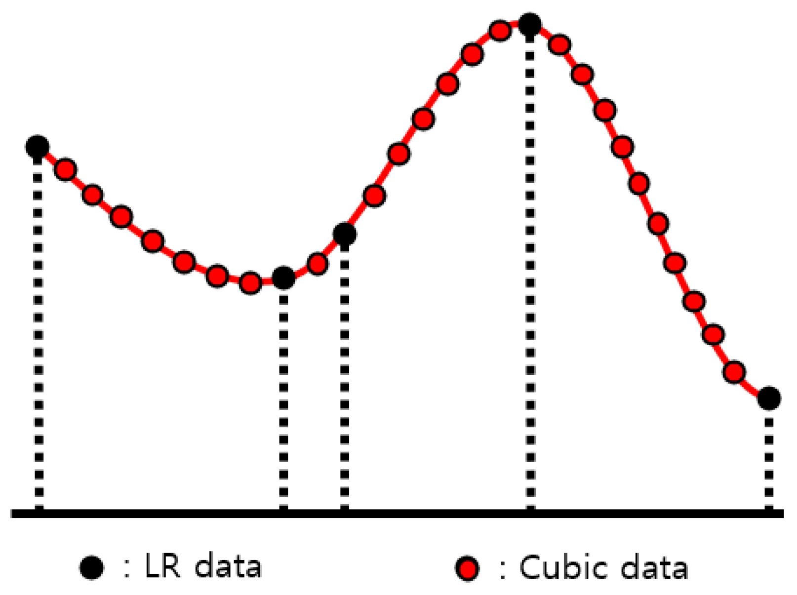
Figure 1. Cubic-interpolation method.
Aerospace 11 00509 g001
Figure 2. Conversion of time series data to image [28]. Adapted with permission from Ref. [28]. 2024, Chong, U.
Aerospace 11 00509 g002
Figure 3. SR3 algorithm architecture.
Aerospace 11 00509 g003
Figure 4. LSTM-AE architecture.
Aerospace 11 00509 g004
Figure 5. Flow chart of fault diagnosis using LR data.
Aerospace 11 00509 g005
Figure 6. Drone arm test equipment for data acquisition.
Aerospace 11 00509 g006
Figure 7. The drone arm HR data collected at a 500 Hz sampling rate, with the x-axis representing time (msec) and y-axis representing acceleration (g): (a) is collected at a normal state; (b) is collected at a fault state.
Aerospace 11 00509 g007
Figure 8. The down-sampled LR data at 8 Hz from HR data, with the x-axis representing time (msec) and y-axis representing acceleration (g): (a) is the down-sampled data from Figure 7a; (b) is the down-sampled data from Figure 7b.
Aerospace 11 00509 g008
Figure 9. CWRU bearing data with (a) data acquisition environment; (b) bearing detail [31]. Adapted with permission from Ref. [31]. 2024, Case Western Reserve University.
Aerospace 11 00509 g009
Figure 10. The 12 KHz CWRU bearing data, with the x-axis representing time (msec) and y-axis representing acceleration (g): (a) is the HR normal data collected at normal states; (b) is the HR fault data collected at fault states.
Aerospace 11 00509 g010
Figure 11. The down-sampled LR data at 8 Hz from HR data, with the x-axis representing time (msec) and y-axis representing acceleration (g): (a) is the down-sampled data from Figure 10a; (b) is the down-sampled data from Figure 10b.
Aerospace 11 00509 g011
Figure 12. Flow chart of training, validation, and testing for anomaly detection.
Aerospace 11 00509 g012
Figure 13. Anomaly detection for (a) drone arm HR data; (b) drone arm LR data. The red dot means reconstruction error value that exceeds the threshold as an anomaly.
Aerospace 11 00509 g013
Figure 14. Anomaly detection for (a) CWRU HR data; (b) CWRU LR data. The red dot means reconstruction error value that exceeds the threshold as an anomaly.
Aerospace 11 00509 g014
Figure 15. Anomaly detection with (a) drone cubic-interpolated data; (b) CWRU cubic-interpolated data. The red dot means reconstruction error value that exceeds the threshold as an anomaly.
Aerospace 11 00509 g015
Figure 16. Normalized drone data in the frequency (Hz) domain: (a) is HR_tr_data; (b) is HR_val_data; (c) is UP_val_data. The red dashed line box highlights the 113Hz frequency domain.
Aerospace 11 00509 g016
Figure 17. Normalized drone data in the time (msec) domain: (a) is HR_tr_data; (b) is HR_val_data; (c) is UP_val_data.
Aerospace 11 00509 g017
Figure 18. Normalized CWRU data in the frequency (Hz) domain: (a) is HR_tr_data; (b) is HR_val_data; (c) is UP_val_data.
Aerospace 11 00509 g018
Figure 19. Normalized CWRU data in the time (msec) domain: (a) is HR_tr_data; (b) is HR_val_data; (c) is UP_val_data.
Aerospace 11 00509 g019
Figure 20. Drone arm anomaly detection result comparison—(a) train: drone arm HR_normal_data, test: drone arm Up_test_data; (b) train: drone arm HR_normal_data, test: drone arm HR_test_data. The black dotted line is the data separation line. The left side of the black dotted line is anomaly detection results for HR_normal_data and the other side is those for Up_test or HR_test_data.
Aerospace 11 00509 g020
Figure 21. CWRU anomaly detection result comparison—(a) train: CWRU HR_normal_data, test: CWRU Up_test_data; (b) train: CWRU HR_normal_data, test: CWRU HR_test_data. The black dotted line is the data separation line. The left side of the black dotted line is anomaly detection results for HR_normal_data and the other side is those for Up_test or HR_test_data.
Aerospace 11 00509 g021
Figure 22. Reconstruction error histograms and kernel density estimation curves: (a) Anomalies’ distribution of drone arm Up_test_data and HR_test_data. (b) Anomalies’ distribution of CWRU Up_test_data and HR_test_data.
Aerospace 11 00509 g022
Table 1. Data name definitions.
Data NameData Definition
HR_normal_dataNormal HR_data for LSTM-AE training
HR_tr_data60% of the HR_data used for SR3 training
LR_tr_dataHR_tr_data modified to low-sampling-rate data
C_tr_dataLR_tr_data cubic-interpolated to the same size as HR_tr_data
HR_val_data10% of the HR_data used for SR3 validation
LR_val_dataHR_val_data modified to low-sampling-rate data
C_val_dataLR_val_data cubic-interpolated to the same size as HR_val_data
Up_val_dataUpscaled C_val_data using the SR3 model
HR_test_data30% of the HR_data used for SR3 testing
LR_test_dataHR_test_data modified to low-sampling-rate data
C_test_dataLR_test_data cubic-interpolated to the same size as HR_test_data
Up_test_dataUpscaled C_test_data using the SR3 model
Table 2. SR3 model hyper-parameters.
ModelEpochsLearning RateBatchThreshold WeightChannels
SR3500,0000.000123CWRU: 8
Drone: 3
Table 3. LSTM-AE model hyper-parameters.
ModelLayerLSTM Cell
Num
EpochsLearning RateBatchThreshold Weight
LSTM-AEEncoder (4 layers)(128/64/32/4)1000.0011003
Decoder (4 layers)(4/32/64/128)
Table 4. DTW Distance Comparison of CWRU Up_val_data.
CaseDE_0HPDE_1HPDE_2HPDE_3HPFE_0HPFE_1HPFE_2HPFE_3HP
HR_tr_data28.724.420.925.931.127.125.424.0
HR_val_data7.16.76.18.38.37.47.06.9
Disclaimer/Publisher’s Note: The statements, opinions and data contained in all publications are solely those of the individual author(s) and contributor(s) and not of MDPI and/or the editor(s). MDPI and/or the editor(s) disclaim responsibility for any injury to people or property resulting from any ideas, methods, instructions or products referred to in the content.