Abstract
Unmanned aerial vehicles (UAVs) with folding wings can serve in multiple mission profiles, usually accompanied by sudden changes in flight speed. These bring great challenges to the aeroelastic design of UAVs, especially in the calculation of flutter characteristics. This paper developed a new non-intrusive aeroelastic model to quickly calculate the flutter characteristics of Z-shaped folding wings at different folding angles. First, the original Z-shaped folding wing was designed to be enhanced. Beams and ribs were arranged inside each wing segment to enhance the structural strength performance. Control surfaces were arranged in the middle-wing and outer-wing to enhance the aerodynamic control performance. Second, a parametric aeroelastic model at any folding angle was reconstructed based on the input file of Nastran software for the flutter calculation of the folding wing in the unfolded state. Finally, the effects of parameters such as folding angle, hinge stiffness between different wing segments, and hinge stiffness of the control surfaces on the flutter characteristics of the folding wing were investigated. The results show that the enhancement scheme could significantly increase the flutter speed and flutter frequency of the folding wing. The hinge stiffness between each wing segment had a significant impact on the flutter characteristics of the folding wing, but flutter at the control surface basically did not occur.
1. Introduction
A UAV with folding wings can adapt to different environments and mission requirements by actively changing the shape of the wings. Variable dihedral angles between each wing segment play important roles in the deformation process throughout the entire mission profile. Compared with a fixed wing aircraft, folding wings can effectively expand the flight envelope by enhancing the aerodynamic characteristics and control autonomy in multi-task environments. This enables UAVs with folding wings to maintain an excellent performance in various environments to meet the mission requirements while addressing formidable threats. In 2007, a Z-shaped folding-wing aircraft concept was proposed by the Lockheed Martin Corporation in the Morphing Aircraft Structure program [1]. Subsequently, flight tests of the folding process were conducted in the NASA-Langley Transonic Dynamics Tunnel.
When the folding angles between adjacent wing segments change, both the structural performance and the aerodynamic performance of the wing will change, which have a significant impact on the aeroelastic characteristics, especially on the flutter performance of the folding wing. In practical engineering calculations, the flutter characteristics of a folding wing can be calculated using the Nastran software 2019, which uses the finite element method (FEM) for structure and the doublet lattice method (DLM) for aerodynamic characteristics. However, due to the fact that the folding angle parameter is a continuous variable that can vary between 0 and 120 degrees, it is difficult to describe the flutter characteristics of the folding wing during the entire deformation process by only examining the folding angles under a few typical operating conditions. On the other hand, establishing a flutter model densely in the folding angle parameter domain would be extremely cumbersome and difficult work. Therefore, how to efficiently and accurately calculate the flutter characteristics of Z-shaped folding wings has become a hot topic in the field of aeroelasticity.
In the last decade or so, some scholars have conducted research on the aeroelasticity of Z-shaped folding wings. Attar et al. [2] modeled a folding-wing structure consisting of three components using a geometrically nonlinear structural dynamics theory based upon von Kármán strains and a three-dimensional vortex lattice aerodynamic model with an exact tangent flow boundary condition and planar wake assumption. Zhao and Hu [3] proposed a parameterized aeroelastic model to investigate the flutter characteristics of a folding wing with different configurations. The results demonstrated that the flutter characteristics of the folding wing were very sensitive to the folding angle. Hu et al. [4] focused on the aeroelastic characteristics of a folding wing during the morphing process. Their results demonstrated that the folding and unfolding processes had opposite influences on the dynamic aeroelastic stability of the folding wing, and the influences became much more significant with an increase in the folding and unfolding rates. Zhang et al. [5] investigated the vibration characteristics of a Z-shaped beam with variable folding angles that was used to model a folding wing of a morphing aircraft under the condition of a fixed structure. Zhang et al. [6] proposed a parametric aeroelastic analysis approach to investigate the aeroelastic stability of a folding wing effectively. Fixed interface component modal synthesis and DLM were used to achieve the aeroelastic model. Verstraete et al. [7] presented a methodology to simulate the unsteady, nonlinear aeroelastic behavior of a folding-wing concept in multiple flight configurations. The fourth-order predictor-corrector method was used to simultaneously integrate the combined set of equations. Xu et al. [8] constructed an aeroelastic flight simulation platform based on the secondary development to simulate the flight-folding process of a folding-wing aircraft to simulate the free-flying morphing process. Huang et al. [9] presented a novel parameterized aeroservoelastic modeling approach for a folding wing with a variation in the folding angle. The most attractive feature of the methodology is that the mathematical aeroservoelastic model of the folding wing with different aerodynamic configurations can be efficiently obtained via the proposed parameterized modeling method. Guo et al. [10] analyzed the nonlinear vibration characteristics of a Z-shaped folded plate composed of three carbon-fiber composite plates through theoretical and experimental investigation. Liu et al. [11] proposed a parametric active aeroelastic control of a folding wing, which is a promising concept of morphing wings, by integrating the parameterized aeroservoelastic model and the reacceptance-based control strategy.
Recently, Yue and Zhao [12] proposed a new approach based on the interpolation of local models to generate the linear parameter-varying model of a folding wing. The model was capable of predicting the aeroelastic responses during the slow morphing process and is suitable for subsequent control synthesis. Zhou and Huang [13,14] presented a novel parameterized nonlinear aeroelastic modeling methodology based on the substructure synthesis of the folding wing with fictitious mass in the hinge joints and piecewise-linear theory. The most attractive feature of the present methodology is that the nonlinear aeroelastic dynamics of the wing can be efficiently represented by piecewise, parameterized, linear subsystems using the parameterized fictitious mode method. Guo et al. [15] investigated the nonlinear dynamic behaviors of Z-shaped morphing wings during the morphing process in subsonic flow based on thin airfoil theory under ideal incompressible fluid conditions. The aeroelastic characteristics of the morphing wing including the flutter displacements of edge points on the outer plate of the wing were investigated using the computational fluid dynamics module. Qi et al. [16] studied the flutter and discrete gust load alleviation characteristics of multi-segment folding wings with a constant cross-section. A bending-torsional beam element was developed to simulate the bending and pitching modes. Aerodynamic lift data of a folding wing at different folding angles were obtained from the modified aerodynamic strip theory. Xie et al. [17] presented the development of an aeroelastic analysis approach for the dynamic response of a Z-shaped folding wing. The coupling relationship between structural and aerodynamics models was proposed innovatively with interpolation between the structural generalized coordinates and incremental normal vectors on the collocation points of aerodynamic panels. Huang et al. [18] employed computational fluid dynamics methods and dynamic meshing to examine the folding process of Z-shaped folding wings to explore the dynamic aerodynamic properties of Z-shaped folding wings at varying upward folding speeds.
In the above literature, different methods were used to model the structure and aerodynamics of folding wings, and corresponding flutter analysis programs were developed for the parameterized aeroelastic analysis of folding wings. However, in the design process of UAVs, the structural layout and aerodynamic shape of folding wings usually need to be continuously adjusted to meet new requirements. At this point, the structural and aerodynamic analysis program needs to be repeatedly modified, and the portability of the program is not strong. On the other hand, currently, the FEM for the structural performance calculation and the DLM for the aerodynamic calculation are relatively mature in the Nastran software, and these calculation results can be directly called by Nastran for flutter analysis. Therefore, if a non-intrusive method based on the Nastran software can be developed to calculate the aeroelastic characteristics of folding wings, it can simplify the flutter analysis process of folding wings and promote it to engineering applications. At present, non-intrusive methods are mostly used in the field of uncertainty quantification and propagation [19,20,21,22,23]. In recent years, some scholars have also begun to use non-invasive methods for research in the field of aeroelasticity [24,25].
Therefore, to our knowledge, there is no literature on the flutter characteristics of folding-wing UAVs based on the non-intrusive method. In this study, first, the wing segments of the existing Z-shaped folding wing were strengthened structurally by arranging wing beams and ribs, and control surfaces were arranged on the middle- and outer-wing segments to enhance the aerodynamic control performance. Afterward, based on the developed MATLAB code and the input files of the Nastran software, the structural node coordinates and aerodynamic grid points were modified due to changes in the folding angle. Finally, based on the p-k method in the flutter calculation, the flutter characteristics of the folded wing under different folding angle conditions were obtained under quasi steady state conditions.
2. Geometric Model of the Modified Z-Shaped Folding Wing
A typical Z-shaped folding wing profile [3] can be divided into three parts, namely, the inner-wing segment , the middle-wing segment , and the outer-wing segment , as shown in Figure 1. These three segments are interconnected through some torsional springs. The model allows for the middle-wing segment to be rotated from 0 degrees (fully unfolded configuration) to 120 degrees (fully-folded configuration) while maintaining the rotation angle of the outer-wing segment at 0 degrees.
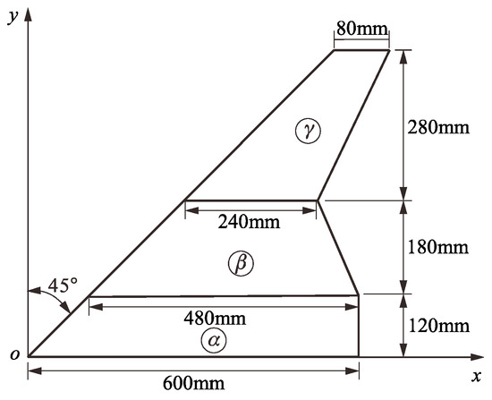
Figure 1.
Folding wing geometries and dimensions.
According to reference [3], the folding wing was made of aluminum plates with the thicknesses of the inner-wing segment, the middle-wing segment, and the outer-wing segment of 2.0 mm, 1.0 mm, and 1.0 mm, respectively. The flutter speed of the folding wing under the fully unfolded configuration was approximately 31.8 m/s, and the second mode became unstable. When the folding angle was 96 degrees, the flutter speed reached its maximum (50.3 m/s), the unstable mode jumped to the fourth mode. However, in practical engineering, it is hoped that the folding-wing UAV has multi-task capabilities (such as reconnaissance, escape, etc.). Obviously, a flight speed of up to 50 m/s cannot meet the requirements. Therefore, it is necessary to effectively expand its flight speed envelope. To this end, we made structural and aerodynamic improvements to the folding wing, as shown in Figure 1. In terms of structure, three longitudinal wing beams and nine transverse wing ribs were added to the folding wing. In terms of the aerodynamic layout, a control surface was added to the middle-wing segment and the outer-wing segment of the folding wing, respectively. Due to the presence of the control surface, the wing beam near the trailing edge in the outer-wing segment was disconnected, as shown in Figure 2. To ensure the correctness of the force transfer path between each wing segment and between the operating surface and the wing surface, 21 torsion springs were added to the folding-wing model. In addition, we also adjusted the thickness of the inner-wing segment and the middle-wing segment to 3 mm and 2 mm, respectively.
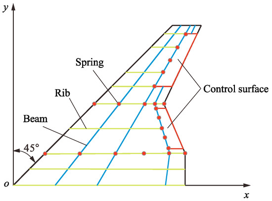
Figure 2.
The modified folding wing.
After strengthening the structural performance and improving the aerodynamic performance, there are two main issues that need to be reconsidered. One is how much the flight speed envelope of the folding wing has been extended, and the other is whether the presence of the control surface will bring new aeroelastic problems such as control surface flutter. Considering the complexity of establishing a series of aeroelastic models for folding wings in the fully-folding angle domain, a highly portable and non-intrusive program was constructed based on MATLAB code by fully utilizing the Nastran software to obtain the flutter characteristics of the folding wing at any folding angle.
3. The Non-Intrusive Method for the Parameterized Aeroelastic Model
To construct a non-invasive parameterized aeroelastic model for the modified folding wing, a reference model at a specific folding angle was required. Naturally, it was appropriate to select the folding wing under the fully unfolded configuration as the reference model.
3.1. Structural Model under Fully Unfolded Configuration
The FEM was introduced to construct a structural model of the modified folding wing under the fully unfolded configuration. The model contained three types of elements: (1) the shell elements used to simulate the wing surfaces and the control surfaces, (2) the beam elements used to simulate the wing beams and the wing ribs, and (3) the spring elements used to simulate the torsion springs, as shown in Figure 3.
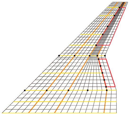
Figure 3.
The finite element model.
For the three wing surfaces and the two control surfaces, the Young’s modulus, Poisson’s coefficient, and mass density of the used material (aluminum alloy) were Pa, 0.33, and kg/m3, respectively. All of the wing surfaces were discretized using the 4-node CQUAD4 element in the Nastran software. Each node of the CQUAD4 element had six degrees of freedom (i.e., three translations , , and three rotations , , ). There was a total of 684 CQUAD4 elements and 945 nodes located at the wing surfaces, and a total of 156 CQUAD4 elements and 165 nodes located at the control surfaces. In addition, a 2-node CBAR beam element type was used for the wing beams and ribs. The beam elements located on the hinge lines used hollow circular cross-sections with outer and inner diameters of 5 mm and 3 mm, respectively. The remaining beam and rib sections were all I-shaped with a width of 6 mm and a height of 8 mm. The thickness of the flange and the web was 1 mm. For the hinges between various wing segments and the control surfaces, 21 multi-point constraints (MPCs) were employed for the simulation, which restrained the five degrees of freedom other than the rotational freedom along the hinge axis. The BAR element was then used on the remaining degrees of freedom to endow them with spring properties.
3.2. Aerodynamic Model under Fully Unfolded Configuration
The geometric configuration of the Z-shaped folding wing is complex, and it is necessary to take into account issues such as mutual interference between various wing segments and the coupling between the wing surfaces and control surfaces during aerodynamic force calculations.
The DLM was used to generate aerodynamic elements for each wing surface and control surface, which were divided into a total of nine aerodynamic surfaces, as shown in Figure 4. The DLM involves dividing the lifting surface such as an aircraft wing into a series of aerodynamic panels or elements in the form of tetrahedrons with sides parallel to the incoming flow. It assumes that the aerodynamic force acting on each panel is concentrated at the intersection of the panel’s mid-chord line and its 1/4 chord line. The boundary conditions are satisfied at the intersection of the panel’s mid-chord line and its 3/4 chord line. By solving the governing equations, the unsteady aerodynamic force distribution on the aerodynamic panels can be determined. The DLM has become a preferred aerodynamic model for calculating the compressible unsteady aerodynamic forces in the subsonic range and is widely used in the design and analysis of aircraft. This method has been successfully integrated into the aeroelastic analysis module of finite element analysis software such as MSC.NASTRAN 2019.
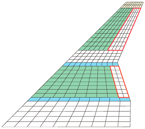
Figure 4.
Aerodynamic panels and elements based on the DLM.
In the aerodynamic grid shown in Figure 4, the inner wing segment is an integral aerodynamic surface with ten chordwise grids and five spanwise grids. Due to the existence of control surfaces, both the middle and outer wing segments were divided into four aerodynamic surfaces, and the grid density remained basically consistent. The entire aerodynamic model consisted of 310 grids, with 50 grids on the inner wing, 100 grids on the middle wing (including 16 grids for the middle wing control surface), and 160 grids on the outer wing (including 40 grids for the outer wing control surface).
It is worth noting that the spatial position of each aerodynamic surface as determined by the coordinates of its four corner points, while the positions of other grid points were determined by specifying the number of chordwise and spanwise grids. Therefore, only the coordinate values of the four corner points on each aerodynamic surface need to be extracted for the subsequent construction of a parameterized aeroelastic model in the folded state.
3.3. Parameterized Aeroelastic Model in the Folded State
As can be seen in Figure 3 and Figure 4, the structural finite element model grid points used in the aeroelastic analysis of the Z-shaped folding wing did not overlap the control points of the aerodynamic model. Therefore, interpolation operations were required to facilitate the mutual transfer of the structural and aerodynamic data. In Nastran, the infinite plate spline (IPS) method can be used to transform the aerodynamic forces on the aerodynamic grid points into equivalent loads on the structural grid points based on the principle of virtual work. The element connection information, node coordinate values of the structural model, the corner point information of the aerodynamic surfaces, the division method of aerodynamic boxes as well as the interpolation information between the structural grid points and the aerodynamic control points were all written into the Nastran input file (*.bdf).
The coordinates of the structural grid points and aerodynamic control points of the inner wing segment were unchanged with the folding angle of the middle wing segment. However, it is necessary to reconstruct the coordinate values of all structural grid points and aerodynamic control points on the middle and outer wing segments. Assuming that in the unfolded state, the lengths of the middle and outer wing segments along the spanwise direction are and , respectively. Let the coordinate values of the structural grid points (or aerodynamic control points) on the middle wing segment be , and the coordinate values of the points on the outer wing segment be . Then, two coordinate transformation relationships
and
hold.
Additionally, since control surfaces were arranged on the middle and outer wing segments, the hinge lines of the control surfaces were defined through the y-axis of the local coordinate system. When the folding angle of the middle wing segment changed to , the spatial position of the hinge line of the control surface also changed, necessitating the redefinition of its local coordinate system. Typically, Nastran uses the CORD2R card to define the hinge line of the control surface, requiring the specification of the origin of the local coordinate system, a point on the z-axis, and a vector in the xz plane. For the middle wing segment, the lower left corner point on the hinge line of the control surface was selected as the origin, denoted as . Together with another corner point () on the hinge line and a certain corner point () on the trailing edge, they spanned the xy-plane of the local coordinate system. After performing the coordinate transformation, the coordinate values of these three corner points were extracted and denoted as , , and , respectively. Therefore, the coordinate value of a certain point on the z-axis after the coordinate transformation can be expressed as
In this way, the yz-plane of the local coordinate system can be determined by points , , and . Similarly, the coordinate value of a point on the x-axis of the local coordinate system can be expressed as
Thus, the definition of the CORD2R card can be completed. Similarly, for the control surface on the outer wing segment, the coordinate values and of the corresponding points on the z-axis and x-axis of the local coordinate system can also be obtained through the corresponding transformations.
The above processes of coordinate transformation for the finite element mesh nodes and aerodynamic grid control points as well as the definition of local coordinate systems were all achieved through MATLAB 2018 reading the *.bdf file, extracting the original node or control point data, calculating the new coordinate values, and then writing them into the corresponding cards.
3.4. Flutter Calculation Method
Based on the constructed non-intrusive aeroelastic model, the p-k method was introduced to calculate the flutter characteristics of the Z-shaped folding wing at a fixed folding angle. The corresponding flutter speed and flutter frequency were extracted from the corresponding f06 file. When the folding angle changed, the node coordinate information in the structural finite element model and the control point coordinate information in the aerodynamic grid were quickly modified by the MATLAB code. The interconnection between the structure and aerodynamics was realized through spline interpolation provided by Nastran. The modified aeroelastic model was then submitted again in the form of a Nastran input file (*.bdf), and the flutter calculation was performed using the p-k method once again.
4. Flutter Calculations and Discussion
During the initial design process, the hinge stiffness between the wing segments was set to 300 , and the hinge stiffness of the two control surfaces was set to 50 . Flutter calculations were performed while ignoring structural damping.
First, flutter calculations were performed on the semi-wing model of the modified folding-wing UAV in its fully extended state at a Mach number of 0.4 using the p-k method. At this point, it is necessary to refer to the modal information of the structural model. The first six modes of the modified folding-wing UAV in its unfolded state are shown in Figure 5. As can be seen from Figure 5, the first four modes exhibited global vibration modes, while the fifth and sixth modes were local, with the maximum displacement occurring at the control surface of the outer-wing segment.
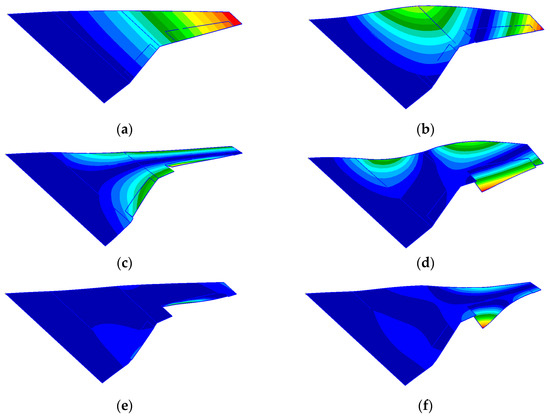
Figure 5.
The first six vibration modes of the folding wing when the hinge stiffness between wing segments was 300 Nm/rad and the hinge stiffness of the control surface was 50 Nm/rad in the unfolded state: (a) the first-order mode; (b) the second-order mode; (c) the third-order mode; (d) the fourth-order mode; (e) the fifth-order mode; (f) the sixth-order mode.
Then, the flutter speed and flutter frequency were extracted and are presented in Figure 6. As shown in Figure 6, the non-matching flutter speed of the modified folding wing in the unfolded state was 192.76 m/s and the corresponding flutter frequency was 47.16 Hz. The flutter occurred in the second mode, manifesting as an uncoupled flutter.
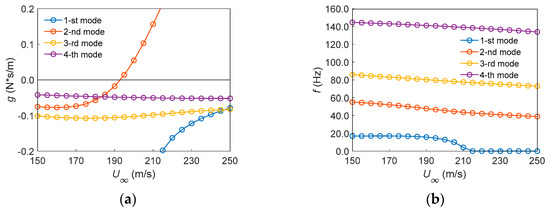
Figure 6.
Flutter characteristics of the modified Z-shaped folding wing: (a) ; (b) .
Compared to the Z-shaped folding-wing unmanned aerial vehicle before improvement in reference [3], the flutter speed increased by approximately 161.0 m/s, representing a significant improvement of 506.3%.
Flutter calculations are typically conducted in modal space. To ensure the accuracy and efficiency of flutter analysis, it is necessary to investigate the impact of the selected modal truncation order on the flutter analysis results. Taking the modified Z-shaped folding wing in its fully extended state as an example, Figure 7 depicts the variation in its flutter speed and flutter frequency with the modal truncation order . As can be seen from Figure 7, in order to obtain the converged flutter speed and flutter frequency, at least the first 16 natural modes of the folding wing should be included in the modal calculation. This approach ensures accuracy while reducing the computational time.
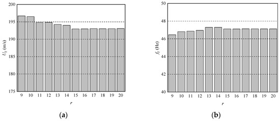
Figure 7.
Variation in flutter speed and flutter frequency with modal truncation order r: (a) ; (b) .
4.1. Natural Frequencies of the Modified Z-Shaped Folding Wing
In the modified Z-shaped folding wing, two types of hinges are included: the hinges between the wing segments, and the hinges of the control surfaces. Letting the stiffnesses of these hinges be and , respectively, the variation in these two parameters will directly affect the distribution pattern of structural stiffness. Therefore, it is necessary to investigate the influence of the variation of these two parameters on the natural frequencies of the system. For convenience, we varied these two parameters based on the initial design (i.e., when examining the influence of , was fixed at 50 Nm/rad, and when examining the influence of , was fixed at 300 Nm/rad). The variations in the first six natural frequencies of the system with and are shown in Figure 8.
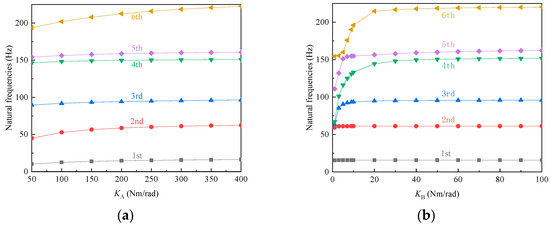
Figure 8.
Relationship between the first six natural frequencies and hinge stiffness. (a) Variation in the first six natural frequencies with hinge stiffness . (b) Variation in the first six natural frequencies with hinge stiffness .
In Figure 8a, the first six natural frequencies all increased as the hinge stiffness between the wing segments increased. Compared to the second and sixth natural frequencies, the growth rates of the other natural frequencies were relatively small. The second natural frequency tended to converge after exceeded 200 Nm/rad, while the sixth natural frequency also tended to converge after exceeded 300 Nm/rad. As can be seen from Figure 8b, as the control surface hinge stiffness increased, the first two natural frequencies of the system remained almost unchanged. When the control surface hinge stiffness was less than 20 Nm/rad, the third to sixth natural frequencies changed drastically, but tended to converge after exceeded 20 Nm/rad. It can be seen that the impact on the natural frequencies decreased as the hinge stiffness increased. For practical folding wings, increasing the hinge stiffness will also increase the driving energy required by the actuator. Therefore, it is essential to select the appropriate hinge stiffness. In the initial design, the choice of and was located in the convergence region, and the lower-order natural frequencies were insensitive to variations in and within a small range.
Next, we studied the effect of changes in the folding angle on the system’s natural frequencies. By keeping the outer-wing segment horizontal and performing modal analysis for the middle-wing segment with folding angles ranging from 0 to 120 degrees in increments of 5 degrees, we could derive the variation pattern of the system’s natural frequencies with respect to the folding angle, as shown in Figure 8.
As seen in Figure 9, there were two significant coupling points in the system as the folding angle increased. One occurred when the folding angle was approximately 20 degrees, where the fourth, fifth, and sixth modes of the system coupled, and the other occurred when the folding angle was approximately 45 degrees, where the second and third modes of the system coupled. In addition, the first-order natural frequency of the system increased as the folding angle increased. The fourth and fifth modes had similar natural frequencies within the folding angle range of 0 to 100 degrees.
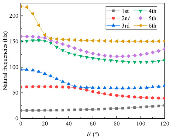
Figure 9.
Variation in the first six natural frequencies with the folding angle .
.
4.2. Flutter Characteristics of the Modified Z-Shaped Folding Wing
As can be seen from Section 4.1, the change in the folding angle of the middle-wing segment will seriously affect the modal properties of the structure, and at the same time, the change in the wing shape will also cause the redistribution of aerodynamic force. Both of them will change the flutter characteristics of the system at the same time. Therefore, it is necessary to investigate the influence of the change of folding angle on improving the flutter characteristics of a Z-shaped folding wing.
With the fixed hinge stiffnesses and set at 300 and 50, respectively, and disregarding the impact of hinge stiffness on the flutter characteristics of the system, the curves showing the variation in flutter speed, flutter frequency, flutter slope, and flutter mode of the original and the modified folding wing with the folding angle could be extracted from the flutter calculation results when the folding angle changed between 0 and 120 degrees, as illustrated in Figure 10.
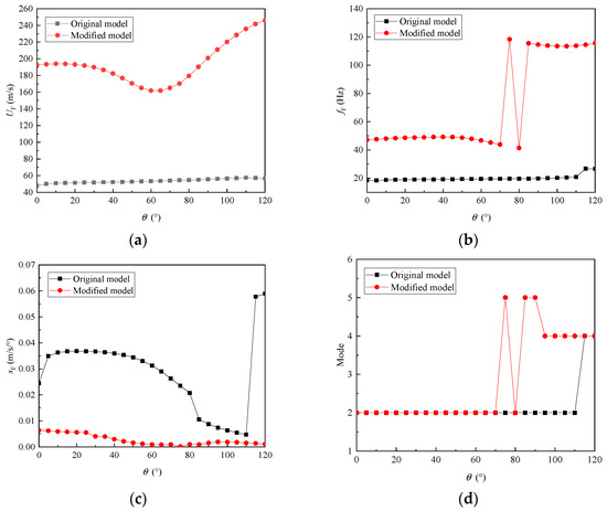
Figure 10.
The variation in flutter characteristics with respect to the folding angle. (a) Flutter speeds. (b) Flutter frequencies. (c) Flutter slopes. (d) Flutter modes.
As depicted in Figure 10, the flutter speed of the modified folding wing exhibited a significant enhancement compared to the original design, with an increase ranging from 66.8% to 76.9%. Notably, as the folding angle progressed from 0 to 70 degrees, the flutter frequency of the modified wing increased by 60.9%. Furthermore, as the folding angle advanced to 120 degrees, the flutter frequency underwent an even more substantial augmentation of 83.4%. At all folding angles, the flutter slope of the modified folding wing was conspicuously reduced compared to the original design. This suggests that the modified wing’s transition into a flutter state was far less abrupt, indicating improved stability and safety.
As can be seen from Figure 10a, the flutter speed of the modified folding wing exhibited a trend of first decreasing and then increasing with the increase in the folding angle. When the folding angle increased from 0 to 65 degrees, the flutter speed decreased by 16% whereas when the folding angle continued to increase to 120 degrees, the flutter speed increased by 51.9%. As can be observed from Figure 10b, when the folding angle was less than 60 degrees, the flutter frequency only underwent minor fluctuations. Subsequently, the flutter frequency became unstable, experiencing continuous jumps between approximately 70 and 80 degrees of folding angle. Once the folding angle exceeded 80 degrees, the flutter frequency entered a stable state again. Compared to before the jumps occurred, the flutter frequency increased significantly, reaching approximately 140.0% higher. In addition, as shown in Figure 10c, as the folding angle increased, the flutter slope generally exhibited a decreasing trend, reaching a minimum at a folding angle of 75 degrees. After a slight increase, it began to decline again. This indicates that at large folding angles, the suddenness of the system entering the flutter state decreased significantly compared to the unfolded state. From Figure 10d, it can be observed that the unstable flutter modes underwent three jumps. Before the folding angle reached 70 degrees, the unstable flutter modes occurred in the second mode and coupled with the first mode. At a folding angle of approximately 75 degrees, the unstable mode jumped to the fifth mode, and the coupled mode also shifted to the fourth mode. However, when the folding angle was around 80 degrees, the flutter mode changed back to the second mode. Subsequently, for folding angles greater than 85 degrees, the mode jumped back to the fourth or fifth mode again.
Certainly, we understand that variations in the hinge stiffness between wing segments can significantly impact the structural inherent properties, thereby altering the flutter characteristics of the modified Z-shaped folding wing. When varying the hinge stiffness , the responses such as flutter speed, flutter frequency, flutter slope, and flutter mode of the modified Z-shaped folding wing under different folding angles were calculated, as illustrated in Figure 11.
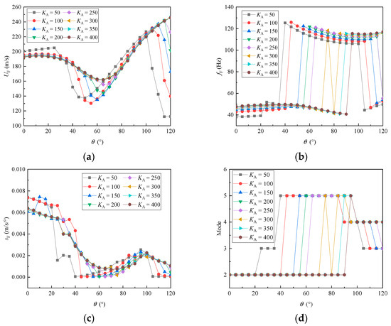
Figure 11.
The variation in flutter characteristics with respect to the folding angle and the hinge stiffness . (a) Flutter speeds. (b) Flutter frequencies. (c) Flutter slopes. (d) Flutter modes.
As seen in Figure 11a, within almost the entire range of values for the hinge stiffness between wing segments, the flutter speed tended to decrease initially and then increase with the increase in folding angle. When the hinge stiffness was relatively small, the flutter speed began to decrease, starting from a folding angle of 40 degrees. Moreover, a sudden drop in flutter speed was observed at large folding angles. However, when the hinge stiffness between wings exceeded 300 Nm/rad, the minimum flutter speed of the system stabilized between folding angles of 60 and 65 degrees. Furthermore, under large folding angles, there was no sudden drop in flutter speed. This suggests that the flutter speed is more sensitive to changes in hinge stiffness at large folding angles. At a folding angle of 120 degrees, when the hinge stiffness was increased from 50 Nm/rad to 400 Nm/rad, the flutter speed of the modified Z-shaped folding wing increased from 109.5 m/s to 242.7 m/s, representing a significant improvement of 121.6%. A can be seen in Figure 11b,d, for all hinge stiffness values within the examined range, the flutter modes underwent jumps as the folding angle increased. Furthermore, as the hinge stiffness increased, the folding angle at which the flutter mode jumped also increased. When the hinge stiffness exceeded 300 Nm/rad, there was no longer a sudden drop in flutter frequency at large folding angles (i.e., the flutter mode no longer jumped from the fourth mode to the third mode). Overall, with the increase in hinge stiffness, the number of mode jumps gradually decreased, and the flutter frequency and flutter mode tended to stabilize, eliminating the occurrence of back-and-forth jumps. In addition, as seen in Figure 11c, when the hinge stiffness was relatively small, for example, less than 100 Nm/rad, the minimum flutter slope occurred near a folding angle of 40 degrees. As the folding angle further increased, the minimum flutter slope tended to concentrate between 60 and 70 degrees. All of the flutter slope curves reached a maximum point near a folding angle of 95 degrees, and then began to decrease to varying degrees.
4.3. Influence of the Hinge Stiffness of the Control Surfaces
Compared to flutter in the overall structure of the aircraft wing, control surface flutter is more common, and most flutter accidents are related to the control surface. When control surface flutter occurs, in many cases, the aircraft has not yet reached the critical speed, and it happens at relatively low speeds. Excluding the coupled flutter between the wing and the control surface, the hinge stiffness of the control surface will be the main factor affecting whether flutter will occur. Next, we examined the variation in the flutter characteristics of the folding-wing UAV with a folding angle under different hinge stiffness values of the control surface. Figure 12 shows the variation curves of flutter speed, flutter frequency, flutter slope, and flutter mode of the modified Z-shaped folding wing with the folding angle under different values.
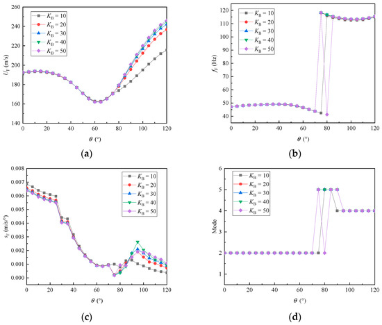
Figure 12.
The variation in the flutter characteristics with respect to the folding angle and the hinge stiffness , which was far from failure stiffness. (a) Flutter speeds. (b) Flutter frequencies. (c) Flutter slopes; (d) Flutter modes.
From Figure 12a, we can see that when the folding angle was less than 75 degrees, the flutter speeds of the folding wing were not sensitive to the hinge stiffness of the control surface (KB). However, when the folding angle exceeded 75 degrees, the flutter speed increased with the increase in hinge stiffness , but the growth rate gradually slowed down and tended to converge. Figure 12b,d show that there was a sudden increase in flutter frequency when the folding angle was between 70 and 80 degrees. The flutter mode jumped from the second mode to the fifth mode, specifically from the second bending mode of the wing to a combined bending-torsion mode. After the folding angle exceeded 90 degrees, the flutter mode jumped back to the fourth mode. As seen in Figure 12c, the minimum flutter slope occurred near a folding angle of 70 degrees. After that, with the increase in hinge stiffness of the control surface, the flutter slope first decreased and then increased, but the values remained within 0.007 m/s/degree. Observing these flutter modes, we can conclude that when the hinge stiffness of the control surface varies between 10 Nm/rad and 50 Nm/rad, the modified Z-shaped folding wing still primarily exhibits flutter of the entire wing. Therefore, when the hinge of the control surface has a certain level of stiffness, the control surface flutter is not easily excited.
However, when the hinge stiffness of the control surface is designed to be too low, or when there is partial failure in the hinge of the control surface, the lower order modes of the system will manifest as local modes of the control surface. Taking KB of 1 Nm/rad as an example, the first six vibration modes of the unfolded folding wing were calculated and are shown in Figure 13.
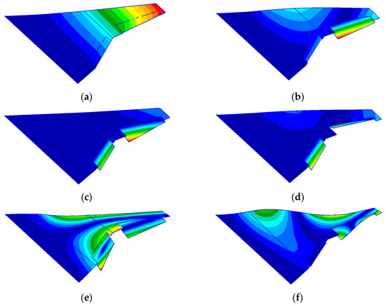
Figure 13.
The first six vibration modes of the folding wing when the hinge stiffness of the control surface was 1 Nm/rad in the unfolded state: (a) the first-order mode; (b) the second-order mode; (c) the third-order mode; (d) the fourth-order mode; (e) the fifth-order mode; (f) the sixth-order mode.
As seen in Figure 13, except for the first mode, which remained as the bending mode of the wing, all other modes were related to the control surface. This suggests that the excitation priority of control surface flutter will be higher than the overall modes of the wing.
Figure 14 presents the variation curves of flutter speed, flutter frequency, flutter slope, and flutter mode when changes from 1 Nm/rad to 6 Nm/rad. As seen in Figure 14, the trend of flutter speed with increasing folding angle was “chaotic”. When = 1 Nm/rad and the folding angle was 120 degrees, the flutter speed dropped to around 50 m/s. At this point, the corresponding flutter frequency was 60 Hz, and the flutter occurred on the third-order mode, which is an isolated control surface flutter without coupling with other modes. However, when = 2 Nm/rad, also at a folding angle of 120 degrees, the flutter speed could reach 250 m/s, but the flutter frequency was lower, approximately 50 Hz. Additionally, the system entered a state of sudden and steep increase in flutter. As continued to increase, the flutter characteristics of the system started to become smoother and exhibited convergence characteristics. Therefore, the hinge stiffness of the control surface should not be set too low. When local failure of the control surface hinge is detected, prompt repairs should be made.
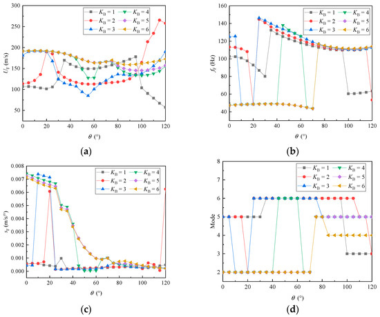
Figure 14.
The variation in flutter characteristics with respect to the folding angle and the hinge stiffness , which was near-failure stiffness. (a) Flutter speeds. (b) Flutter frequencies. (c) Flutter slopes. (d) Flutter modes.
4.4. Influence of the Modal Damping
In the aforementioned studies, the influences of structural modal damping were not considered, which tends to make the structural design overly conservative. The presence of structural damping can absorb energy from the vibration system, potentially delaying the flight speed at which the modified Z-shaped folding wing enters the flutter critical state. This section will investigate the variation in the flutter characteristics of the aeroelastic system with folding angle, taking into account the influence of the modal damping ratio in the structural dynamics equations.
By introducing structural damping through the modal damping ratio in the aeroelastic system, allowing it to vary from 0 to 0.1, Figure 15 presents the variation curves of the flutter speed, flutter frequency, flutter slope, and flutter mode extracted after the flutter calculations. As seen in Figure 15a, compared to the undamped case, the aeroelastic system with modal damping ratios exhibited higher flutter speeds and smoother transition states. Around a folding angle of 110°, the flutter speed of the aeroelastic system with modal damping ratios reached a maximum value and converged as the modal damping ratio increased.
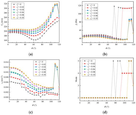
Figure 15.
The variation in the flutter characteristics with respect to the folding angle and the modal damping. (a) Flutter speeds. (b) Flutter frequencies. (c) Flutter slopes. (d) Flutter modes.
From Figure 15b,d, it can be observed that as the modal damping ratio increased, the transition of flutter modes started to delay, and the jump amplitude of the flutter frequency decreased. Additionally, as shown in Figure 15c, when the folding angle was less than 105°, the flutter slope curves representing different damping ratios decreased as the folding angle increased. However, when the folding angle exceeded 105°, the flutter slope curves underwent a sudden change and exhibited a maximum value near 110°.
To better illustrate the impact on the flutter characteristics of the system when parameters such as hinge stiffness and modal damping ratio changed simultaneously, the flutter speeds were calculated under four characteristic folding angles (30°, 60°, 90°, and 120°), as shown in Figure 16.
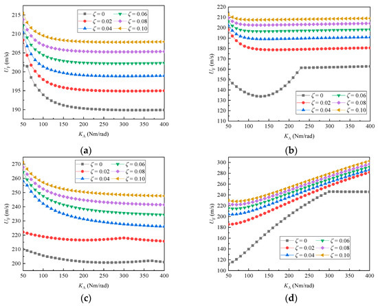
Figure 16.
The variation in flutter speed with hinge stiffness and modal damping ratio under different folding angles: (a) ; (b) ; (c) ; (d) .
As depicted in Figure 16, the flutter speeds exhibited a clear trend of increasing with the rise in modal damping ratio across all of the characteristic folding angles. However, this increase in flutter speed began to taper off and converge once the modal damping ratio reached a critical threshold. Furthermore, when the folding angle was relatively small, a slight decrement in flutter speed was observed as the hinge stiffness between the wing sections increased, followed by a stabilization of the flutter speed. Conversely, at larger folding angles, the flutter speed of the system exhibited a monotonic increase as the hinge stiffness was enhanced.
5. Conclusions
The structural and aerodynamic performance of the traditional Z-shaped folding-wing UAV was enhanced by the arrangement of beams, ribs, and control surfaces on different wing segments. Based on non-intrusive methods, a parameterized aeroelastic model of the modified Z-shaped folding wing was constructed. Using the p-k method, flutter calculations were performed on the aeroelastic models under different folding angles. The main conclusions are as follows:
- The natural frequency characteristics of the system are jointly influenced by the hinge stiffness between each wing segment, the hinge stiffness of the control surfaces, and the folding angle. The hinge stiffness parameters between wing segments mainly affect the second and fifth modes, while the hinge stiffness of the control surfaces will no longer affect the low-order mode characteristics of the system when it is sufficiently large. As the folding angle increases, the fourth, fifth, and sixth modes first undergo coupling, and then the second and third modes of the system undergo coupling.
- As the folding angle increases, the flutter modes of the system undergo several transitions, with the number of transitions varying depending on the value of the hinge stiffness between wing segments. Concurrently, the flutter frequency also exhibits sudden changes. When the hinge stiffness between wing segments is small, the flutter speed first decreases, then increases, and finally decreases again as the folding angle increases. The maximum flutter speed occurs near a folding angle of 105 degrees, reaching approximately 230 m/s. However, as the hinge stiffness between wing segments continues to increase, the maximum flutter speed will occur at a folding angle of 120 degrees. Overall, as the folding angle increases, the suddenness of the system entering flutter decreases, but a local maximum point appears near 95 degrees.
- When the hinge stiffness of the control surface exceeds 10 Nm/rad, the system generally does not experience control surface flutter. However, if the hinge stiffness of the control surface experiences local failure, resulting in a lower residual stiffness, the low-order modes begin to be invaded by local modes at the control surface, and the system starts to experience control surface flutter.
- When modal damping ratio is taken into account, the flutter behavior of the system appears more smooth, and the flutter speed and flutter frequency obtained are higher than those in the undamped case. As the injected modal damping ratio increases, the flutter speed of the system also increases, however, there may be an unfavorable situation of a steep increase in the flutter slope under large folding angles.
Author Contributions
Conceptualization, W.Q. and S.T.; Methodology, W.Q.; Software, S.W.; Validation, W.Q.; Formal analysis, W.Q.; Investigation, S.W.; Resources, S.T.; Data curation, S.W.; Writing—original draft preparation, S.W.; Writing—review and editing, W.Q.; Visualization, S.W.; Supervision, W.Q.; Project administration, W.Q.; Funding acquisition, W.Q. All authors have read and agreed to the published version of the manuscript.
Funding
This research was funded by the National Natural Science Foundation of China (grant numbers 11502149 and 12002218) and the Project of Liaoning Provincial Department of Education (grant numbers JYTMS20230253, JYT2020034, and JYT2020029).
Data Availability Statement
Data are contained within the article.
Conflicts of Interest
The authors declare no conflicts of interest.
References
- Love, M.H.; Zink, P.S.; Stroud, R.L.; Bye, D.R.; Rizk, S.; White, D. Demonstration of Morphing Technology through Ground and Wind Tunnel Tests. In Proceedings of the 48th AIAA/ASME/ASCE/AHS/ASC structures, structural dynamics, and materials conference, Waikiki, HI, USA, 23–26 April 2007; Volume 2007, p. 1729. [Google Scholar]
- Attar, P.J.; Tang, D.M.; Dowell, E.H. Nonlinear Aeroelastic Study for Folding Wing Structures. AIAA J. 2010, 48, 2187–2195. [Google Scholar] [CrossRef]
- Zhao, Y.H.; Hu, H.Y. Parameterized Aeroelastic Modeling and Flutter Analysis for a Folding Wing. J. Sound. Vib. 2012, 331, 308–324. [Google Scholar] [CrossRef]
- Hu, W.; Yang, Z.C.; Gu, Y.S. Aeroelastic study for folding wing during the morphing process. J. Sound. Vib. 2016, 365, 216–229. [Google Scholar] [CrossRef]
- Zhang, W.; Hu, W.H.; Cao, D.X.; Yao, M.H. Vibration Frequencies and Modes of a Z-Shaped Beam with Variable Folding Angles. J. Vib. Acoust. 2016, 138, 041004. [Google Scholar] [CrossRef]
- Zhang, W.; Lv, S.L.; Ni, Y.G. Parametric Aeroelastic Modeling Based on Component Modal Synthesis and Stability Analysis for Horizontally Folding Wing with Hinge Joints. Nonlinear Dyn. 2018, 92, 169–179. [Google Scholar] [CrossRef]
- Verstraete, M.L.; Roccia, B.A.; Mook, D.T.; Preidikman, S. A Co-simulation Methodology to Simulate the Nonlinear Aeroelastic Behavior of A Folding-wing Concept in Different Flight Configurations. Nonlinear Dyn. 2019, 98, 907–927. [Google Scholar] [CrossRef]
- Xu, H.; Han, J.L.; Yun, H.W.; Chen, X.M. Calculation of the Hinge Moments of a Folding Wing Aircraft during the Flight-Folding Process. Int. J. Aerosp. Eng. 2019, 2019, 9362629. [Google Scholar] [CrossRef]
- Huang, R.; Yang, Z.J.; Yao, X.J.; Zhao, Y.H.; Hu, H.Y. Parameterized Modeling Methodology for Efficient Aeroservoelastic Analysis of a Morphing Wing. AIAA J. 2019, 57, 5543–5552. [Google Scholar] [CrossRef]
- Guo, X.Y.; Zhang, Y.; Zhang, W.; Sun, L. Theoretical and Experimental Investigation on the Nonlinear Vibration Behavior of Z-shaped Folded Plates with Inner Resonance. Eng. Struct. 2019, 182, 123–140. [Google Scholar] [CrossRef]
- Liu, H.J.; Gao, X.M.; Wang, X. Parametric Active Aeroelastic Control of a Morphing Wing using the Receptance Method. J. Fluid Struct. 2020, 98, 103908. [Google Scholar] [CrossRef]
- Yue, C.Y.; Zhao, Y.H. Interpolation-Based Modeling Methodology for Efficient Aeroelastic Control of a Folding Wing. Int. J. Aerosp. Eng. 2021, 2021, 8609211. [Google Scholar] [CrossRef]
- Zhou, X.H.; Huang, R. Efficient Nonlinear Aeroelastic Analysis of a Morphing Wing via Parameterized Fictitious Mode Method. Nonlinear Dyn. 2021, 105, 1–23. [Google Scholar] [CrossRef]
- Huang, R.; Zhou, X.H. Parameterized Fictitious Mode of Morphing Wing with Bilinear Hinge Stiffness. AIAA J. 2021, 59, 2641–2656. [Google Scholar] [CrossRef]
- Guo, X.Y.; Wang, S.S.; Qu, Y.G.; Cao, D.X. Nonlinear Dynamics of Z-shaped Morphing Wings in Subsonic Flow. Aerosp. Sci. Technol. 2021, 119, 107415. [Google Scholar] [CrossRef]
- Qi, W.C.; Zhao, C.X.; Liu, B.H.; Tian, S.M. Flutter and Discrete Gust Load Alleviation Characteristics of Multi-segment Folding Wings with Constant Cross Section. J. Sound. Vib. 2022, 54, 117312. [Google Scholar] [CrossRef]
- Xie, C.C.; Chen, Z.Y.; An, C. Aeroelastic Response of a Z-shaped Folding Wing During the Morphing Process. AIAA J. 2022, 60, 3166–3179. [Google Scholar]
- Huang, Y.C.; Guo, X.Y.; Cao, D.X. Aerodynamic Characteristics of a Z-Shaped Folding Wing. Aerospace 2023, 10, 749. [Google Scholar] [CrossRef]
- Keshavarzzadeh, V.; Fernandez, F.; Tortorelli, D.A. Topology Optimization under Uncertainty via Non-intrusive Polynomial Chaos Expansion. Comput. Methods Appl. Mech. Eng. 2017, 318, 120–147. [Google Scholar] [CrossRef]
- Abdedou, A.; Soulaimani, A. A Non-intrusive B-splines Bezier Elements-based Method for Uncertainty Propagation. Comput. Methods Appl. Mech. Eng. 2019, 345, 774–804. [Google Scholar] [CrossRef]
- Mocayd, N.E.; Mohamed, M.S.; Seaid, M. Non-intrusive Polynomial Chaos Methods for Uncertainty Quantification in Wave Problems at High Frequencies. J. Comput. Sci. 2021, 53, 101344. [Google Scholar] [CrossRef]
- Huo, H.; Xu, W.T.; Wang, W.P.; Chen, G.H.; Yang, D.X. New Non-intrusive Stochastic Finite Element Method for Plate Structures. Comput. Struct. 2022, 268, 106812. [Google Scholar] [CrossRef]
- Duan, Y.; Ridao, M.N.; Eaton, M.; Bluck, M. Non-intrusive Semi-analytical Uncertainty Quantification using Bayesian Quadrature with Application to CFD Simulations. Int. J. Heat Fluid Flow 2022, 93, 108917. [Google Scholar] [CrossRef]
- Savin, E.; Hantrais-Gervois, J. Sparse Polynomial Surrogates for Non-intrusive, High-dimensional Uncertainty Quantification of Aeroelastic Computations. Probabilist. Eng. Mech. 2020, 59, 103027. [Google Scholar] [CrossRef]
- Cea, A.; Palacios, R. A Non-intrusive Geometrically Nonlinear Augmentation to Generic Linear Aeroelastic Models. J. Fluid Struct. 2021, 101, 103222. [Google Scholar] [CrossRef]
Disclaimer/Publisher’s Note: The statements, opinions and data contained in all publications are solely those of the individual author(s) and contributor(s) and not of MDPI and/or the editor(s). MDPI and/or the editor(s) disclaim responsibility for any injury to people or property resulting from any ideas, methods, instructions or products referred to in the content. |
© 2024 by the authors. Licensee MDPI, Basel, Switzerland. This article is an open access article distributed under the terms and conditions of the Creative Commons Attribution (CC BY) license (https://creativecommons.org/licenses/by/4.0/).