1. Introduction
A helicopter is a complex engineering product whose development, design, and production require technical, financial, human, and other resources. Helicopter aerodynamics adds another level of complexity, appearing during a stationary hovering flight with wind or any movement in three-dimensional space because of the asymmetric aerodynamic flow around the main rotor. This results in different airflow velocities and, therefore, different local angles of attack around the blade profile [
1]. Due to their complex mechanical, electrical, and hydraulic systems, helicopters face potential critical emergencies. These include power plant failures, partial or complete loss of control, and transmission failures, which may occur due to design inaccuracies, intensive or incorrect helicopter operation, metal fatigue, structural damage caused by mechanical issues, etc.
In addition to the mentioned technical failures, the complex aerodynamics of helicopters can lead to other challenging situations, such as dangerous aerodynamic phenomena. In such situations, an aircraft may partly lose lifting power, have diminished controllability, may be affected by large vibrations, etc. The current study focuses on one such aerodynamic phenomenon—the Vortex Ring State (VRS).
A VRS is a hazardous phenomenon (
Figure 1), typically causing a sudden decrease in main rotor thrust, increased vertical descent rate, diminished maneuverability, and power deficiency [
2]. The conditions for VRS formation typically involve a steeper descent with reduced engine power, relatively low horizontal speed
Vh, and a reasonably significant vertical descent rate
Vz [
3,
4]. In a favorable situation, with sufficient space, altitude, theoretical knowledge, and practical skills, corrective maneuvers can allow the helicopter to exit the Vortex Ring State and continue routine flight without any residual consequences [
4,
5,
6,
7]. However, problems arise when the distance to the ground or obstacles become dangerously short during such a steep descent with low horizontal speed. During these events, entering a Vortex Ring State leaves insufficient vertical height reserve, making the corrective actions ineffective.
Maintaining a safe altitude is necessary because effectively recognizing and recovering from a VRS requires time and altitude. VRSs become critically dangerous if they occur at low altitudes. It should be emphasized that no helicopter pilot, regardless of the helicopter type, is immune to encountering a VRS and facing all the subsequent consequences. In global practice and as per EASA-approved crew licensing regulations, helicopter pilot students receive mandatory theoretical and practical introduction to the Vortex Ring State phenomenon. This practice is reasonable, given that an unprepared pilot faced with this dangerous aerodynamic phenomenon may encounter catastrophic consequences if unable to navigate out of such a situation. Entering a Vortex Ring State while flying close to the ground can be dangerous. Thirty-two helicopter accidents [
9,
10], spanning from 1982 to 1997, have been linked to this phenomenon, with a significant majority occurring at altitudes up to 200 feet (~61 m).
An analogous example of helicopter Vortex Ring State training is the Upset Prevention and Recovery Training (UPRT) course in commercial and airline transport pilot training programs for airplanes. Student pilots must become familiar with special cases, including stall event recovery and spin recovery (source: Easy Access Rules for Flight Crew Licencing (Part-FCL)). Airplanes have a technically simple device for warning pilots when approaching a dangerous stall. However, helicopters do not have practical warning systems to signal dangerous approaches to a Vortex Ring State [
11]. The existence of proven warning devices is currently precluded by the aerodynamic complexity of the phenomenon [
12,
13], and conditions conducive to vortex formation. In such conditions, pilots need to recognize the phenomenon and take exact corrective actions immediately.
Small rotary-wing UAVs for military and civilian purposes are of interest, owing to their size and lightweight nature [
14,
15,
16,
17]. A typical design of a four-propeller system arranged in pairs, which generates significant vortices, is employed here. Several studies have employed the Blade Element Momentum (BEM) model to analyze the aerodynamics of these small-scale propellers. However, the model’s accuracy diminishes when strong three-dimensional effects arise from the propeller’s geometry and/or operating conditions [
18]. Numerical [
12,
13] and experimental [
19,
20] results show that when multiple propellers rotate simultaneously nearby, they individually experience reduced thrust due to flow interaction and interference among the propellers, compared to a single isolated propeller. The literature review shows a gap in the investigation of vortex ring phenomena. While basic principles are known, individual adaption to each helicopter model is needed [
1,
21,
22,
23]. Research on small, two-seat helicopters is notably scarce. These smaller helicopters are frequently employed in practical scenarios, such as initial helicopter pilot training, necessitating pilots’ familiarity with the VRS phenomenon. Consequently, this study focuses on the Cabri G2 helicopter manufactured by Hélicoptères Guimbal, conducting an in-depth analysis of this model, determining the limits of conditions conducive to vortex ring development, and simulating this aerodynamic phenomenon.
2. Object of the Investigation
The main objective of this study is to analyze a specific helicopter in various possible flight scenarios to identify its safe and unsafe flight modes that must be avoided in standard flight operations. We will conduct a computer analysis using a replicated digital model of a Cabri G2 helicopter’s main rotor to determine the specific aerodynamic conditions that lead to Vortex Ring States.
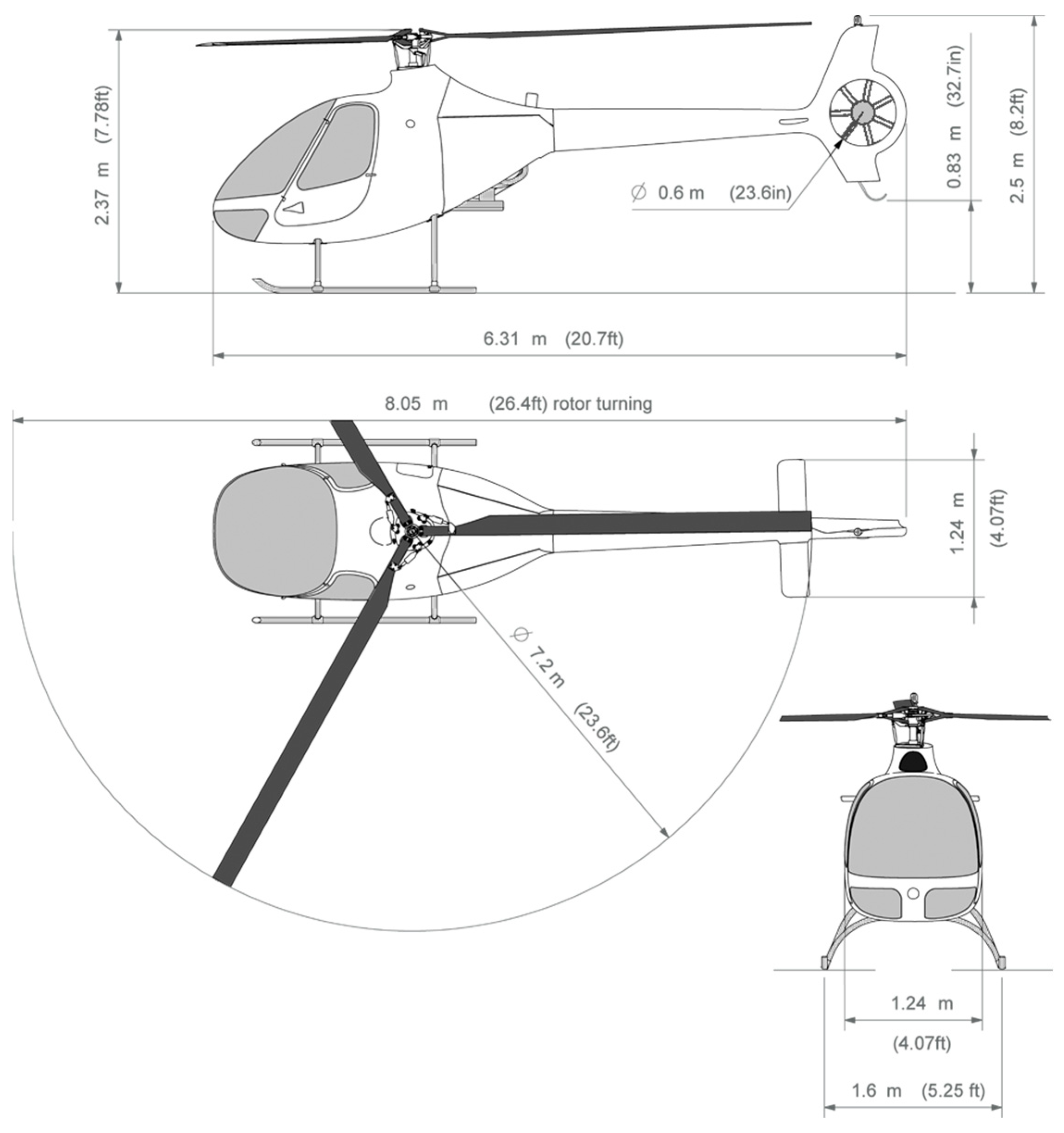
Three views and the main dimensions of the helicopter Cabri G2 are given in
Figure 2.
The Cabri G2 is a light two-seat piston-engine helicopter with a shrouded fenestron tail rotor, a composite fuselage, and a four-cylinder, carbureted gasoline power plant. The Cabri G2 is designed with occupant protection as the priority. Therefore, it has a crash-resistant fuel cell and energy-absorbing crash-resistant seats.
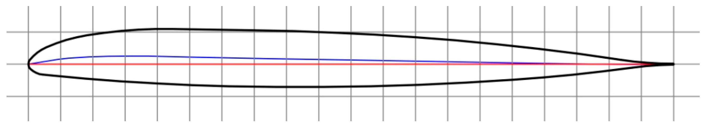
The helicopter’s main rotor has three composite blades (
Table 1). There is no twist in the helicopter rotor blades, which means that the pitch angle from root to tip is constant. They rotate in a clockwise direction when viewed from above. The blades are a carbon–fiberglass-reinforced composite, with a large internal steel tip weight, and lead balance weight. This helps to ensure that the rotor has high inertia, which is a critical parameter in the event of an engine failure. Their fork attachment is directly connected to an elastomeric, spherical thrust bearing, which ensures pitch, flap, and lead–lag motions. An airfoil of the blade is shown in
Figure 3.
2.1. Setup of VRS Analysis
Typically, VRS analysis uses simplified assumptions due to the high CPU resource requirements. Some researchers employ an empirical extension of momentum theory [
1], while others employ a computational fluid dynamics (CFD) solver based on the Navier–Stokes equations.
Some papers use a detailed helicopter body with simplified primary rotor geometry [
6], while others incorporate detailed main rotor geometry but omit the helicopter fuselage [
24]. Each approach has advantages and disadvantages. This study investigates the flow phenomena around the main rotor, focusing solely on the main rotor’s contribution. This approach allows for a better understanding of VRS flow behavior because the main lift and drag forces predominantly occur near the blade tips (~
R = 0.75) and within the main rotor disk area.
The simulation model consists of two bodies (
Figure 4a): body 1 is a fixed cylinder, while body 2 is drawn up with the blades (
Figure 4b) embedded into the larger body and rotates about the
Z-axis at an
n = 530 RPM and a blade pitch angle of 7.5°.
A constant change in vertical velocity
Vz (
Figure 4a,b) from 0 m/s to 16 m/s in 18 s was generated for all cases, with various horizontal velocities
Vx = 0, 2, 4, 6, 8, 9, 10, and 12 m/s (in total, eight cases were modeled).
2.2. Sensitivity Analysis
The meshing strategy, including the size and dimensions of the calculation domain, significantly affects the numerical model’s accuracy and requires consideration of CPU resources. Therefore, we performed an investigation of mesh density, ranging from 0.008 to 0.014 m (1); the diameter of the calculation domain, within 25–40 m (2); and the height of the calculation domain, within 25–40 m (3). The analysis revealed the sensitivity of these parameters to the lift and moment of rotation of the helicopter blades.
The calculation domain size causes up to 1% variations for both thrust and moment outputs, a minor influence on the obtained results. However, for further calculations, the diameter of static domain
D will be set to 30 m and the height of the domain to
H = 30 m (see
Figure 5).
A sensitivity study of blade surface size shows that a mesh size of up to 0.01 m is sufficient; a further decrease in mesh size has no significant effect on thrust and moment results. These parameters will be used for the full-scale 360° model to investigate the VRS effect for the given helicopter (see
Figure 6).
The validation of numerical results (see
Figure 7), which involved comparing simulations and experiment tests for the main rotor thrust, revealed qualitative consistency but also some detailed differences. For instance, the thrust-settling seen in [
25] data occurs over a narrower range of descent speeds (4 <
Vz < 7.2) compared to the simulation’s range (4.2 <
Vz < 6). However, from a qualitative perspective, both the simulation and [
25] data exhibit a distinct rise in thrust level after the thrust-settling episode. Thrust fluctuations are typical in numerical investigations due to instabilities causing vortices to detach from organized structures, leading to significant thrust oscillations [
23,
26].
Based on [
22], in hover conditions, the rotor has no vertical and forward speed, and the thrust compensates for the helicopter’s weight such that
T = W. Then, the conservation of the mass flow rate
remains constant in the wake of the rotor. Hence, we have
where
,
,
, and
denote mass flow, fluid density, velocity change through the propulsion system, and the area that is swept out by the rotor of blade length, respectively. This can be simplified to
where
,
A, and
denote angular velocity, disk area of the main rotor, and induced velocity during hover, respectively. However, the rotor thrust is equal in magnitude and opposite in direction to the force exerted on the fluid, which is given by
After additional simplifications,
For further calculations, the main rotor’s average induced velocity
during hovering serves as a reference value. It will be used to define the VRS region by normalizing the vertical descent
Vz and horizontal
Vx velocities later. The formula to find
Vi [m/s] is
It should be noted that the empty weight of the Cabri G2 helicopter is 430 kg (the weight may vary slightly depending on its configuration). For the Vi calculations, it was assumed that the helicopter’s mass during the simulation was 560 kg, including the pilot and fuel weights. This constitutes about 80% of the Cabri G2’s maximum permissible take-off weight (700 kg). After applying Formula (5), the calculated average induction airflow speed in the stationary hover flight is Vi = 7.42 m/s.
3. Results
The CFD modeling of the given simulations provides a visual representation of the movement of air gas particles around the aerodynamic body. Such graphical representations show more precise insights into the processes occurring around the rotating rotor (see
Figure 8). As mentioned above, conditions conducive to VRS occur during flights under reduced engine power and specific vertical and horizontal velocity combinations. The VRS is characterized by recirculating airflow around the main rotor, preventing the rotorcraft from escaping the vortices generated [
26]. The shape of the resulting vortex is roughly toroidal. The center of the resulting cloud of vortices is situated in or just above the main rotor’s rotation plane [
25]. The mentioned recirculation of air vortices, occurring at vertical and horizontal velocities of
Vx = 4 m/s and
Vz = −9 m/s, respectively, indicates the helicopter’s entry into the VRS boundary region.
Figure 8c displays the generated toroidal or doughnut-shaped [
11] vortex cloud formed around the main rotor’s rotation plane. Meanwhile, at speeds of
Vx = 9 m/s and
Vz = 0 m/s, the produced vortices lag behind and beneath the rotor (see
Figure 8a). When the horizontal velocity is 8 m/s and the vertical descent is 12 m/s, the main rotor’s plane remains relatively unaffected by the generated vortices (see
Figure 8b). For clarity, all four mentioned cases are illustrated in
Figure 9. This figure confirms that the helicopter is only within VRS conditions in two cases.
Simulations were performed to determine the VRS region for the Cabri G2 helicopter, involving a transition from hover to a gradually increasing vertical descent, reaching
Vz = 18 m/s while maintaining the blades at a fixed pitch position. A key sign of entering the upper VRS region is a noticeably decreased thrust generated by the main rotor, accompanied by specific thrust fluctuations (with peaks occurring approximately every 0.5 s) [
21]. As vertical speed increases, the helicopter reaches the lower limit of VRS, i.e., departs from VRS and enters “the Windmill-brake State” detected at high descent speeds (
Vz). In this zone, the airflow becomes uniform again. The transition is characterized by a specific change in the thrust curve, manifested by a change in the pattern of thrust fluctuations. After establishing the VRS start and end points at a horizontal velocity
Vx = 0 m/s, the simulations were extended to include horizontal velocities
Vx = 0, 3, 4, 6, 7, 8, and 9 m/s. The results of these simulations are shown in
Figure 9.
The graph’s vertical axis represents normalized vertical descent; the horizontal axis represents normalized horizontal speed. The calculated VRS region of the Cabri G2 is shown in blue. The presented curves show that the upper limit of the calculated VRS region closely coincides with the profiles of Newman and Onera, and the lower limit closely resembles Onera. The shape of the region is very close to the Newman model. The tangent l derived from the origin (0; 0) for the calculated VRS region forms an angle of ϕ = 35.2°. This determined angle does not contradict the statement [
17] that there is no evidence of a VRS’s existence for descent angles below 30 degrees.
A Cabri G2 helicopter flight was carried out to validate the VRS calculations. The flight executed all four cases depicted in
Figure 8, corresponding to
Vz and
Vx flight parameters. Each case was replicated across four flights, resulting in sixteentest flights. At the speeds described in
Figure 8a,b, there were no characteristic signs of the helicopter entering VRS conditions, aligning with the computational simulations, which suggested that the Cabri G2 was unlikely to enter a VRS in the mentioned flight modes. While flying in the other two cases described in
Figure 8c, i.e., at a horizontal speed of
Vx—4 m/s and vertical speed of
Vz—9 m/s, no significantly pronounced signs of VRS were observed, indicating mild cyclic stick vibrations and a slight increase in vertical speed
Vz. These symptoms were noted while entering VRS at nearly zero horizontal speed (
Vx—0.5 m/s) and a vertical speed of
Vz—6.5 m/s. Typically, signs of entering VRS conditions were observed in two or three out of four attempts for these cases. The meteorological conditions during the physical flight test closely mirrored those of the simulation conditions, with a 4.34% pressure reduction and a 13°C lower temperature. There was a light wind of ~4 m/s, making it difficult to maintain the necessary flight modes. These findings suggest that further physical flights, closely replicating the simulated conditions, are necessary to delineate the VRS region more precisely.
4. Conclusions
According to the VRS region calculations, Cabri G2 pilots can confidently perform safer flights with minimal risk of entering the dangerous VRS effect.
During the motorized flight, when the engine operated within 20–80% of the maximum power at any vertical Vz and horizontal Vx speeds, VRS conditions was not determinedwhen the angle of descent was less than ϕ = 35.2°.
During hovering, when the value of Vx was zero or above, entry into the VRS was not detected when the vertical speed was below 0.5 times Vi.
When flying at a horizontal speed Vx > 1.05 Vi, entry into the VRS did not occur regardless of vertical descent speed Vz.
During hovering, entry into the VRS was not detected when the vertical descent rate exceeded 1.56 times the velocity Vi, regardless of the horizontal velocity Vx.
The physical flight tests conducted with the Cabri G2 helicopter validate the numerical investigation results, demonstrating the CFD method’s applicability in determining the VRS region. Conducting additional flight tests to set the VRS boundary zone would increase the accuracy of predicting this dangerous effect.
Note: The calculations, graphs, and VRS region shown here are not instructions for pilots on how to conduct actual flights. This is simply an academic approach to a problem that every helicopter can face. The final results of entering a VRS will depend on the helicopter’s configuration, weight, meteorological conditions, erosion or dirt covering the aerodynamic surfaces, piloting technique, and other parameters. Each of these factors, individually or in certain combinations, may change the boundaries of the VRS region determined in this research.


