Abstract
The compressor serves as a crucial component that influences the performance of the gas turbine engine. Researchers have been endeavoring to explore compressor types that possess a high loading level and high-efficiency characteristics concurrently. In this study, tandem blade technology was applied to a transonic ultra-highly loaded axial compressor, and the Baseline single-blade rotor was replaced by a tandem rotor to take into account the loading level and compressor performance. Detailed investigations were carried out to identify the effects on the aerodynamic performance of the ultra-highly loaded stage and the fundamental flow mechanism within the tandem-rotor stage. This paper presents original design maps for the tandem-rotor stage, and the selection criteria for tandem parameters in tandem-rotor stage are refined. The results indicate that the peak efficiency improved by 0.83%, the stall margin increased by 2.16%, and the choke flow rate rose by 0.30% for the optimal tandem-rotor configuration. The meridional division position of the rotor primarily affects the ratio of loading of the front and rear blades, while the circumferential relative position of the tandem rotor mainly influences the channel types formed by the front and rear blades. Larger values for the meridional division position parameter and smaller values for circumferential relative position parameter should be selected for the tandem rotor design to optimize both the isentropic efficiency and total pressure ratio. This investigation offers the theoretical foundation for the design of a transonic ultra-highly loaded tandem-rotor compressor.
1. Introduction
The compressor is the critical component of an aircraft gas turbine engine, as it significantly influences the reliability and stability of the engine and directly determines important performance parameters, such as the trust-to-weight ratio, power, and fuel consumption. Hence, the compressor has always been a focal point for researchers. With the ongoing pursuit of a high thrust-to-weight ratio, fuel efficiency, and meeting the power demands of aircraft with higher cruising speed, the high-pressure compressor has emerged as a vital research area in advanced compressor technology [,].
The increase in flight speeds of modern fighter jets leads to the absolute total temperature of the high-pressure compressor inlet airflow being higher, which decreases the reduced linear velocity of the blade. As a result, the loading level will increase if the total pressure ratio is constant. At present, the loaded coefficient of the advanced compressor is generally below 0.40, and the limit is about 0.46. In comparison to the general loaded compressor, the rotor of the highly loaded compressor must have a larger blade camber angle. As a result, the large blade camber angle will intensify the adverse pressure gradient within the blade passage and aggravate boundary layer flow separation on the blade surface []. Therefore, the rising flow separation loss due to the increase in the compressor loading level leads to a decrease in efficiency and surge margin, which is unsuitable for engineering applications. Tandem blade is a common high-load blade type with advantages such as low loss and a large airflow turning angle. The design concept of the tandem blade can be traced back to the use of slotted flaps on aircraft wings. By using multiple separated fins on the wings of an aircraft, the goal is to avoid stall and increase wing lift. This design concept was later borrowed into the field of aeroengines. As a structurally simple but effective passive flow control method, tandem blade technology is based on the principle of replacing the single blade with two independent blades. Tandem-blade configuration rebuilds the boundary layer on the suction side of the blades through the gap between the front and rear blades, reducing the flow separation loss []. Previous studies have shown that the tandem blade exhibits a superior aerodynamic performance compared to the conventional single blade for conditions of a high rotor power and large blade turning angle. There is a promising prospect for the tandem-blade technology to be adopted in ultra-highly loaded compressors.
Experimental and numerical simulation studies about two-dimensional tandem-blade cascades are relatively abundant. There is a wealth of conclusions demonstrating that the arrangement of the tandem blades offers lower loss and higher efficiency in highly loaded compressors. Bammert and Beelte [] applied tandem-rotor cascade technology in the three stages of a five-stage compressor. After the installation angle of the stator was adjusted to the optimal value, the tandem-rotor compressor achieved a high total pressure ratio and high efficiency over a wide operating range. Extensive overall engine tests also demonstrated that the compressor with tandem-blade technology does not present any other issues, indicating the potential application of tandem-blade technology. Saha and Roy [] combined Controlled Diffusion Airfoil (CDA) with tandem cascade. Through an experimental comparison in a low-speed cascade wind tunnel, they evaluated the performance of the single-blade and tandem-blade cascade. The results indicated that tandem-blade cascade has a larger flow turning angle with acceptable flow loss. The study of McGlumphy et al. [] presented that the tandem-blade cascade designed by the simple design criteria performed lower energy loss when the DF was above about 0.45. The authors also paid attention to the percent pitch and axial overlap of the tandem-blade cascade. And the value of percent pitch and axial overlap of the optimum tandem-blade configuration should be large and low, respectively [,]. Liu [] redefined a parameter E for assessing the stall margin based on a two-dimensional maximum static pressure-rise model. Guided by the E parameter, they designed single-blade stages and tandem-blade stages. Then, they conducted an experimental verification on a large low-speed test rig. The results showed that the tandem rotor can break the pressure-rise limit near the stall conditions, thus demonstrating that tandem blade can enhance the efficiency of a highly loaded compressor and expand the stall margin, thereby raising the loading level of axial flow compressors. Mao [] conducted a parameterization study of highly loaded tandem cascades with different load splits and chord length ratios. The results indicated that load split is a crucial design parameter that can be used to regulate performance under off-design conditions. Luo [] investigated the flow losses and vortex structures in curved tandem cascades with different curved angles and an original straight tandem cascade. This author performed numerical simulations at different incidence angles. The results showed that the influence of the curved angle on the aerodynamic performance of a curved cascade is inconsistent. The tandem cascade with a curved angle of 5° effectively reduces losses at all incidence angles, while the tandem cascade with a curved angle of 15° extends the critical incidence angle to 3°. Zhang [] adopted the Delayed Detached Eddy Simulation (DDES) to calculate and analyze the complex flow characteristics in the tip region of a tandem cascade with tip clearance. The results showed that the tip load of the rear blade increases and the tip load of the front blade decreases compared with the reference cascade. The unsteady fluctuation of the tandem cascade is mainly caused by the interaction between tip leakage flow and gap jet and the mixing of vortex structure, but there is no essential change in the spectrum feature of the tip leakage flow.
Research about the application of tandem blades in the 3D environment of compressors had already begun in the 1970s. Brent and Clemmons [] designed a single-blade rotor and two different types of tandem rotors and conducted experiments on them. The results showed that the maximum efficiency of the tandem rotor reached 91.8%, and both types of tandem rotors had a stall margin of 17%. Eshraghi [] designed a tandem blade stage based on the transonic single-blade stage. The results showed that the total pressure ratio of the stage increased by 9.3% after the tandem blade was adopted, but the isentropic efficiency decreased by approximately 3%. Kumar et al. [,,,,] conducted extensive numerical simulation and experimental studies based on the single-stage low-speed tandem rotor. Their research covered various aspects, including the performance of the tandem rotor in off-design conditions [,], inflow distortions [], tip clearance size [], spike type of stall in the tandem [], and sweep configurations. Through their studies, the researchers enhanced the understanding of the internal flow mechanism of the tandem rotor. However, owing to the fact that the rear blade is operated with positive preswirl and a lower degree of reaction, the diffusion of the flow is inadequate, thus leading to a higher absolute Mach number at the rotor outlet. As a result, the design of the stator is challenging. Consequently, the efficiency and stall margin of the tandem rotor were both unsatisfactory in the early days. For example, Hasegawa [] adopted the tandem rotor in the transonic high-pressure ratio fan of an Air Turbo Rocket (ATR) engine. The experimental results showed that it could achieve a total pressure ratio of 2.2 at the design speed, but the efficiency was only 77%. Burger and Keenan [] designed a single-stage compressor. The rotor tip speed was 490 m/s, and the total pressure ratio was 1.94, but the efficiency of the stage is only 83.1% at the design point. In addition, the efficiency will be reduced to a lower level under the inflow distortion conditions. Sakai [] optimized the clearance between the front and rear blades. The isentropic efficiency was raised to 84.9%. Nonetheless, the stall margin remained relatively low. With the advancement of tandem-blade cascade technology, the problem of rotor efficiency and stall margin has been solved. Mohsen [] used Rotor37 as the Baseline and obtained the modified tandem rotor via the axial segmentation method. Through the further optimized design of the tandem configuration, the aerodynamic performance of the rotor was improved across all operating conditions, with a 17% increase in the total pressure ratio and a 2% increase in the isentropic efficiency at the design point. Liu [] studied the tip flow field of highly loaded tandem rotors by experimental and numerical simulation methods. The results show that, compared with conventional rotors, the stable development stage of the tip leakage vortex in the tandem rotor is prolonged due to the pressure gradient of the front and rear blade throat, which is conducive to reducing the flow blockage of rotor tip caused by the tip leakage vortex.
From the review of studies about 2D and 3D tandem blades, it is evident that tandem blade technology can enhance the efficiency of highly loaded compressors. However, studies in the literature on ultra-highly loaded compressors are mostly limited to conditions with subsonic inflow. And it is challenging to overcome the limitations of ultra-highly loading level in transonic inflow condition. Nevertheless, the application of tandem-rotor technology in ultra-highly loaded compressors with transonic inflow condition has not been thoroughly studied or summarized yet. In addition, the internal flow mechanism of ultra-highly loaded tandem-rotor compressor remains unclear.
Drawing on the research background mentioned above, this study investigated a transonic ultra-highly loaded tandem-rotor stage. And detailed investigations were carried out to identify the effects on the aerodynamic performance of ultra-highly loaded stage and the fundamental flow mechanism within the tandem-rotor stage. Moreover, the design maps for the tandem-rotor stage were constructed, and the selection criteria for tandem parameters in the tandem-rotor stage were refined. This study provides a theoretical foundation for the application of the tandem rotor in ultra-highly loaded compressors.
2. Research Model and Numerical Method
2.1. Research Model
This paper presents a study focusing on the first stage of a four-stage axial high-pressure compressor (HPC). The schematic diagram of the basic configuration is depicted in Figure 1, while the aerodynamic design parameters of the Baseline are detailed in Table 1.
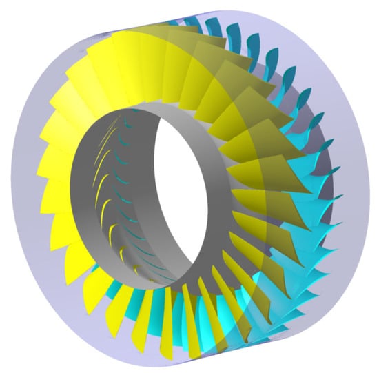
Figure 1.
Schematic diagram of Baseline stage configuration.

Table 1.
Aerodynamic design parameters of the Baseline.
In order to explore the internal flow mechanism of the tandem rotor in the stage, this study maintained the stator parameters of the single-blade stage (Baseline). The Baseline rotor is modified to the tandem rotors with different tandem parameters. The performance differences of Baseline and tandem-rotor stage, as well as among various tandem configurations, are compared and summarized at great length. For the tandem-rotor stage, geometric parameters such as the circumferential relative position of the front and rear blades, the meridional division position of the rotor blades (), and the axial overlap (AO) of the front and rear blades play a crucial role in determining the aerodynamic performance of tandem rotor. This study also investigated the mechanism of the circumferential relative position of the tandem rotor coupled with the meridional division position of the tandem rotor on the aerodynamic performance of the stage. To enhance the sensitivity of the interaction between the front and rear blades of the tandem rotor and eliminate the influence of the AO, the of the front and rear blades is set to +1 mm in this study. Figure 2 illustrates a schematic diagram of the tandem-rotor design. As shown in Figure 2a, the red lines represent five different meridional division positions. Lines I, II, III, IV, and V represent = 30%, 40%, 50%, 60%, and 70% tandem-rotor configurations, respectively. To facilitate the subsequent analysis, the circumferential relative position parameter between the front and rear blades is defined as follows:
where represents the number of blades, which is 27 in this paper. It is specified that is positive when the rear blade deflects along the rotor rotation direction, and the axial position parameter can be positive or negative. When is positive, the front and rear blades do not overlap axially. On the contrary, when is positive, there is axial overlap between the front and rear blades.
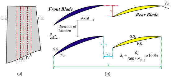
Figure 2.
(a) Schematic diagram of the blade meridional division position. (b) Schematic diagram of the circumferential relative position of front and rear blades.
To ensure the comparability of research conclusions between the Baseline and the tandem-rotor stage, the same design principle of the tandem rotor was followed. As shown in Figure 2b, the single-blade rotor is divided into the front blade and the rear blade for the tandem-rotor stage based on the Baseline. Subsequently, the total axial chord length (X) of the front and rear blades is adjusted to be equal to the axial chord length of the Baseline rotor. Meanwhile, the value of is selected to be +1 mm. To ensure that the rear blade is adjusted to match the outlet flow of the front blade, adjust the inlet angle of the rear blade to maintain the incident angle at the design point operating condition to be zero. Meanwhile, the total blade turning angle of the front and rear blades is equal to the blade turning angle of the Baseline rotor. In the process of tandem-rotor design, the original parameters, such as the meridional flow path, number of blades, inlet and outlet flow angle, blade angle, throat area, etc., are kept consistent with those of the Baseline. Based on the above design principle, the tandem-rotor stages with different tandem parameters ( and ) can be obtained.
2.2. Numerical Method
The three-dimensional CFD software NUMECA FINE/Turbo (NUMECA 16) is utilized for numerical calculations in this paper. The steady-state solutions are based on the 3D steady Reynolds-averaged Navier–Stokes equations with the time-marching technique. The turbulence model adopted is the Spalart–Allmaras single-equation turbulence model, which ensures high accuracy while maintaining computational efficiency. The fourth-order explicit Runge–Kutta method is selected for time-marching, while the finite volume central differencing scheme is adopted. The CFL number is set to 3.0. Local time stepping, multigrid technology, and implicit residual smoothing methods are adopted to accelerate the convergence of flow field calculation. At the inlet of the stage, the total temperature and total pressure boundary conditions are specified (288.15 K and 101,325 Pa). The airflow at the stage inlet is in the axial direction, and static pressure boundary condition is specified at the stage outlet. The interface between the rotor and stator adopts the mixing-plane method to transfer flow field information. All solid wall surfaces, including the hub, are set with adiabatic and no-slip boundary conditions. The detailed boundary conditions and calculation settings are shown in Table 2. In previous studies, it was shown that the numerical method used in this paper provides sufficient accuracy for predicting internal flow in turbomachinery [,,,].

Table 2.
Boundary conditions used for CFD analysis.
In this paper, the judgment of compressor stall point needs two steps:
- (1)
- Firstly, whether the numerical calculation is convergent is investigated. If the numerical calculation diverges, the previous convergent point is taken as the compressor near stall point.
- (2)
- When the numerical calculation converges, it is necessary to observe the trajectory of the compressor blade tip clearance leakage flow. If the clearance leakage flow overflows from the leading edge of the blade, the previous convergent point is taken as the compressor near stall point.
In this paper, the Autogrid module in the NUMECA software (NUMECA 16) is adopted for the model grid division. The topology structure for the blade surface is HOH, while O4H is adopted for the topology structure of the rotor blade tip clearance. The first grid layer thickness near the wall surface is set to 0.003 mm. According to the requirements of the turbulence model, the normalized distance of the first layer mesh y+ is approximately 1. All grids are structured hexahedral meshing, and the computational grids for the stage are illustrated in Figure 3. To better capture flow details within the stage flow field, local refinement of the grids is applied to areas such as the casing, hub, and clearance between the front and rear blades.
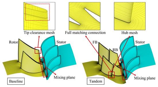
Figure 3.
Numerical simulation grids.
First, three sets of grids with different densities are chosen to conduct grid independence verification for the Baseline and tandem-rotor stage. The number of coarse grids for the Baseline and tandem-rotor stage are 1.5 million and 3 million, respectively. The medium-density grid G2 and high-density grid G3 are both refined based on the coarse grid G1. Figure 4 presents the performance characteristics of the stage for different grid configurations. The results indicate that further refining the grid has a minimal impact on the calculation results when the grid count for the Baseline reaches 2 million (G2) and for the tandem-rotor stage reaches 4 million (G2). Therefore, the study considers that grid G2 has fulfilled the criteria for grid independence.
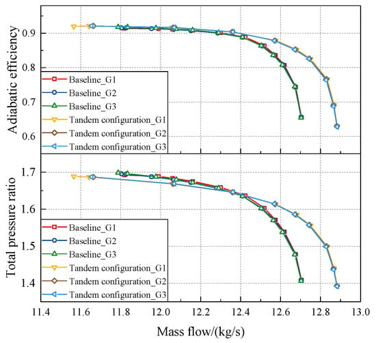
Figure 4.
Grid independence verification (100% rotation speed).
Then, a grid with a density level G2 is selected to validate the characteristics of the 1.5-stage compressor, which has similar dimensions and loaded coefficient (0.46) to the Baseline. The experimental validation was carried out on the compressor test rig with a maximum shaft power of 800 kW []. During the experiment, the compressor outlet back pressure was gradually increased from the near choke point (NC) to near stall point (NS), and the highest back pressure point at which the numerical simulation diverged was determined as NS. Comparison of calculated results and measured data at design rotation speed are compared in Figure 5. As shown in Figure 5a, the total pressure ratio obtained from the numerical simulation agrees well with the experimental results. Although the isentropic efficiency value obtained from the numerical simulation is slightly lower than the experimental value, the overall trend is consistent. And as shown in Figure 5b, the total pressure ratio and isentropic efficiency radial distribution of the compressor outlet obtained through numerical calculation also have good consistency with the experimental measurement results. And as shown in Table 3, there is no significant difference in the flow rate of the choke point with the change of the number of grids. Therefore, it can be considered that the numerical simulation results almost reproduce the experimental results, indicating that the accuracy of the numerical method adopted in this study is sufficient for predicting the aerodynamic performance and internal flow of turbomachinery.
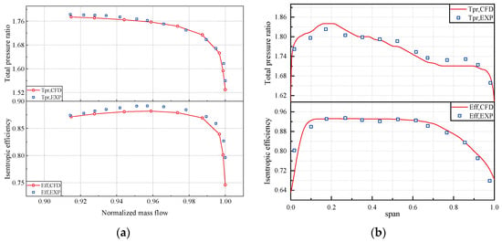
Figure 5.
(a) Compressor characteristics curves. (b) Radial distributions of the total pressure ratio and isentropic efficiency.

Table 3.
Choke mass flow rate of different mesh configurations for Baseline and tandem-rotor stage.
3. Results and Discussions
3.1. Analysis of the Mechanism of Meridional Division Position
Based on the tandem-rotor stage design principle, as described above, the tandem-rotor stages with different meridional division positions were developed. The circumferential relative position between the front and rear blades was maintained at = 15%. This section aims to explore the impact of different meridional division positions on the performance of tandem-rotor stage and the internal flow mechanism. In this section, five different tandem-rotor stages with meridional division positions of 30%, 40%, 50%, 60%, and 70% are considered. Figure 6 presents the performance gains of peak isentropic efficiency (PE), stall margin (SM), and choke point mass flow rate (mchoke). These performance variation parameters are defined as follows:
where and , respectively, represent the PE of the Baseline and tandem-rotor stage; and , respectively, represent the mass flow rate of the Baseline and tandem-rotor stage at NS; and and , respectively, represent the total pressure ratio of the Baseline and tandem-rotor stage at NS.
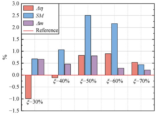
Figure 6.
Comparison of aerodynamic performance gains for tandem-rotor stages with different meridional division positions.
Overall, for different meridional division positions, the performance of the tandem-rotor stage exhibits a certain regularity. fluctuates significantly with , reaching its peak when = 60% and dropping to its lowest when = 30%. The difference between the highest PE gain and the lowest PE gain is approximately 1.82%. When = 50%, 60%, 70%, the PE increases, while when = 30% and 40%, the PE decreases. Additionally, shows an increasing and then decreasing trend with the increase in . The trend of SM changes is basically consistent with that of . SM increases first and then decreases as increases, but SM always remains positive. When = 60%, the SM and PE of the tandem-rotor stage increased by 2.5% and 0.92%, respectively. While when = 30%, the SM of the tandem-rotor stage increased by 0.68%, but the PE decreased by 0.9%. In addition, the mchoke of all tandem-rotor stages with different meridional division positions is increased, which indicates that the through-flow capability of the tandem-rotor stages is enhanced.
Furthermore, the aerodynamic performance differences between the tandem-rotor stages and the Baseline at the design rotational speed were determined (Figure 7). When the tandem-rotor configurations ( 50%, 60%, and 70%) were adopted, the efficiency of the stage significantly improved, and the flow capacity of the tandem-rotor stage was also further increased. The flow margin is widened, which means that the stable operating range of the tandem-rotor stage is broader. When the flow rate is greater than 12.4 kg/s, the tandem-rotor stage can achieve a positive benefit in total pressure ratio. When the flow rate is less than 12.4 kg/s, although the total pressure ratio of the tandem-rotor stage may slightly decrease, the maximum total pressure ratio value between the tandem-rotor stage and Baseline is almost the same. Therefore, the tandem rotor can improve the aerodynamic performance of the ultra-highly loaded stage. In addition, tandem-rotor stages with different values also exhibit different patterns in aerodynamic performance. The efficiency of the tandem-rotor stage is lower at the NS and higher at the NC when = 60% and 70%. However, it is superior to the Baseline overall. When = 50%, the efficiency of the tandem-rotor stage is high across the entire operating range. When = 30% and 40%, the efficiency of the tandem-rotor stage is higher than the Baseline only at the NC.
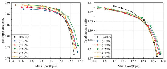
Figure 7.
Comparison of the aerodynamic performance of tandem-rotor stages with different meridional division positions and Baseline (design rotational speed).
In this paper, the efficiency of the ultra-highly loaded stage mainly depends on two key components, the rotor and stator. For the tandem rotor, different meridional division position directly affects the matching of the front and rear blades, thereby influencing the overall efficiency of the tandem rotor. Figure 8 presents the aerodynamic performance of tandem rotors with different values. Compared to the aerodynamic performance of the entire tandem-rotor stage, the aerodynamic performance of the tandem rotor does not show a significant choking condition, indicating that the throat of this tandem-rotor stage should be located within the stator passage. Furthermore, the aerodynamic performance variation rules of the tandem rotors and tandem-rotor stages are similar. In other words, the aerodynamic performance of tandem rotor determines that of the entire stage for different values.
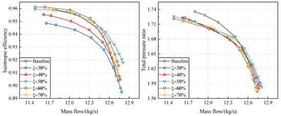
Figure 8.
Comparison of the aerodynamic performance of tandem rotors with different meridional division positions (design rotational speed).
In this section, the stator of the tandem-rotor stage is not redesigned. In order to evaluate the performance characteristics of the stator of tandem-rotor stage, the total pressure loss coefficient (Cpt) of the stator is used to characterize the magnitude of stator energy loss level, defined as follows:
where Pt,inlet is the absolute total pressure at the stator inlet, Pt,outlet is the absolute total pressure at the stator outlet, and Ps,inlet is the static pressure at the stator inlet.
Figure 9 shows the aerodynamic performance comparison of stators of tandem-rotor stages with different division positions. When the flow rate is less than 12.6 kg/s, the stator has the highest Cpt compared to other tandem-rotor stages when = 30% after the tandem-rotor stage departs from the NC. Furthermore, the variation in the Cpt of the stator is not significant when changes. The Cpt shows almost no difference especially when the compressor is far from the NC. Based on this, it can be inferred that the aerodynamic performance of tandem-rotor stage is mainly determined by the tandem rotor. Therefore, the aerodynamic performance and internal flow mechanism of the tandem rotor should be further investigated for the research on tandem-rotor stages with different meridional division positions.
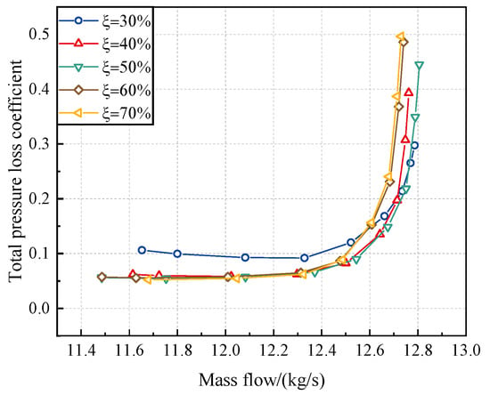
Figure 9.
Aerodynamic performance comparison of stators of tandem-rotor stages with different division positions.
Compared to the Baseline, the PE of the tandem-rotor stage is significantly improved when = 50%, 60%, and 70%. To explore the influence of different meridional division positions on the performance of the tandem rotor and the internal flow mechanism, it is essential to clarify the fundamental reasons for the efficiency improvement. Figure 10 presents the comparison of the circumferential averaged isentropic efficiency spanwise at the tandem rotor outlet and Baseline rotor outlet. Efficiency variation is calculated by subtracting the efficiency of the Baseline at the same span from that of the = 60% tandem rotor.
where represents the efficiency of tandem configuration, and represents the efficiency of Baseline at the same span.
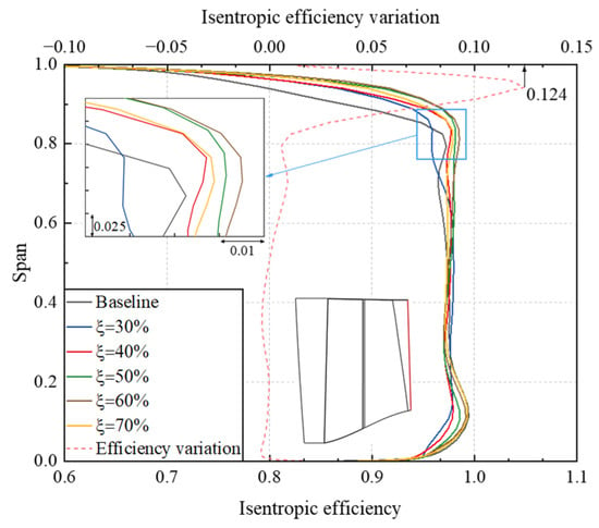
Figure 10.
Comparison of the circumferential averaged isentropic efficiency spanwise at the tandem rotor with different meridional division positions and Baseline rotor outlet.
In the region from 80% span to the tip, the isentropic efficiency of the = 60% tandem rotor is significantly higher than the isentropic efficiency of other tandem-rotor configurations and Baseline. Only the isentropic efficiency of the = 30% tandem rotor is lower than the isentropic efficiency of Baseline. When comparing the distribution of isentropic efficiency variation along the spanwise between = 60% tandem rotor and Baseline, we see that the largest variation occurs near 95% span, with a maximum absolute difference of approximately 1.24%. In the region below 80% span, the efficiency variation is relatively small. Based on this, it can be inferred that the main reason for the tandem rotor efficiency improvement should be the improvement of flow field quality in the region from 80% span to the tip.
Furthermore, Figure 11 presents the meridional view of the circumferential averaged entropy distribution of tandem rotors with different meridional division positions. It can be observed that the entropy distribution in the lower span region of the tandem rotor shows no significant difference compared to the entropy distribution in the lower span region of the Baseline. However, the = 50%, 60%, and 70% tandem rotors exhibit a noticeable reduction in high-entropy region near the tip compared to the Baseline. It is precisely due to the reduction in high-entropy region near the tip that the isentropic efficiency of the = 50%, 60%, and 70% tandem rotors is higher than that of the Baseline. However, for the = 30% and 40% tandem rotors, although the high-entropy region near the tip is smaller, there is an increase in the moderate entropy region from approximately 70% span to 90% span, which leads to lower isentropic efficiency.
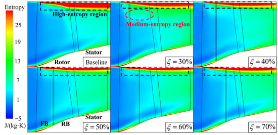
Figure 11.
Meridional view of the circumferential averaged entropy distribution of tandem rotors with different meridional division positions.
In order to reveal the physical mechanism of the isentropic efficiency variations among tandem rotors with different meridional division positions near the rotor tip region (from 80% span to the tip), a detailed analysis of the flow field in this region is conducted by combining the relative Mach number (Mar) contour and entropy contour at 95% span, as shown in Figure 12 and Figure 13. There is a shock wave in the rotor passage, known as the blade passage shock wave at the 95% span. However, for the tandem rotors with different meridional division positions, the morphology of the blade passage shock wave also exhibits different characteristics. When = 30% and 40%, the position of the passage shock wave is close to the front blade trailing edge (T.E.) due to the shorter chord length of the front blade, resulting in the transformation of the blade passage shock wave into a shock wave. After adopting the tandem-rotor configuration, a contraction channel is formed between the front blade T.E. and the rear blade leading edge (L.E.), with the throat of the channel located at the T.E. of the rear blade. The airflow passing through this contraction channel will accelerate, which is caused by the ‘nozzle effect’ []. When = 30%, the front blade is shorter and the deceleration of the airflow in the front blade channel is not sufficient. After passing through the contraction channel, it is accelerated again to supersonic speed, so there is still a weak shock wave at the rear blade L.E. for the 30% tandem rotor. Meanwhile, when = 50%, 60%, and 70%, there is no significant difference in the strength and position of the shock wave.
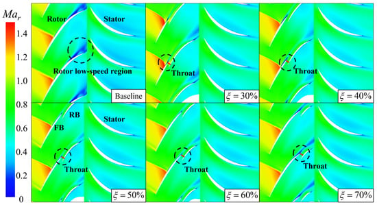
Figure 12.
Relative Mach number of tandem rotors with different meridional division positions at 95% span.
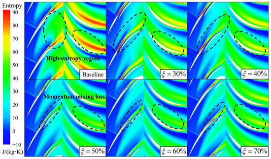
Figure 13.
Entropy of tandem rotors with different meridional division positions at 95% span.
From the perspective of energy loss, the high-entropy region of the tandem rotor is significantly reduced in the vicinity of 95% span. Meanwhile, for tandem rotors with different meridian division positions, the distribution of entropy also shows a certain regularity. When = 30% and 40%, the high-entropy region at the front blade T.E. is larger. When = 50% and 60%, the high-entropy region at the front blade T.E. becomes smaller. That is the reason why the isentropic efficiency of the = 50% and 60% tandem rotors is higher. However, as continues to increase, the flow separation loss of the front blade increases again. As a result, the isentropic efficiency of the = 70% tandem rotor decreases, but it is still higher than the isentropic efficiency of the Baseline. Therefore, as a passive flow control method, tandem-rotor stages with appropriate values of can reduce the loss of the near tip region of the rotor, thereby improving the isentropic efficiency of the ultra-highly loaded stage.
For the purpose of revealing the differences of flow characteristics in the rotor of tandem configurations with different meridional division positions, Figure 14 shows the limiting streamlines of rotor suction side (S.S.). Firstly, there is a separation line (SL) generated by shock wave/boundary layer interaction near the blade L.E. for both the Baseline and tandem rotors. However, the difference is that a clear SL appears on the Baseline rotor suction side, and the secondary flow structure after the SL is very obvious. On the one hand, the rotor camber angle is large due to the high loading level. The airflow continues to decelerate in the diffusion channel composed of adjacent blades. Thus, it is difficult for the boundary layer flow with low momentum level to resist the strong adverse pressure gradient, resulting in a large boundary layer flow separation. On the other hand, the radial transport capacity of the low-energy fluid near the wall of the rotor is enhanced, which migrates to the tip and middle of the rotor. After the single rotor is divided into two blades, the SL is also divided into two (SL1 and SL2). When = 50% and 60%, the SL is located below about 60% span of the front blade (SL1) and at the T.E. of the rear blade (SL2), respectively. It can be seen that the overall strength of the rotor S.S. flow separation is obviously weakened, especially in the region above 60% span. Thus, it can be approximately considered that the SL in the region above 60% span is delayed to the rear blade T.E. Therefore, the = 50% and 60% tandem rotors’ limiting streamlines are more uniform, and the radial transport capacity of the low-energy fluid near the wall of the rotor is inhibited significantly, which is the main reason why the efficiency of = 50% and 60% tandem rotors in the region above 60% span is higher than that of Baseline. Then, the = 60% tandem rotor with the best performance is selected to be compared with the Baseline regarding the blade loading distribution. The rotor S.S. static pressure is normalized and characterized by reduced static pressure (Pre), which is defined as follows:
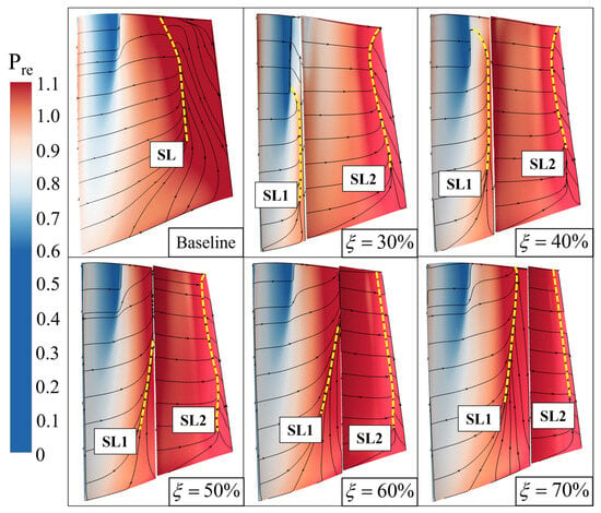
Figure 14.
Comparison of the limiting streamlines on the suction side of the tandem rotors with different meridional division positions.
As shown in Figure 15, the loading distributions of the front blade of the tandem rotor and Baseline rotor are basically the same at 95% span, and the main difference is in the rear blade. The adverse pressure gradient of the Baseline S.S. is very strong. Moreover, the boundary layer flow with a low momentum level makes it difficult to overcome this adverse pressure gradient, resulting in large-scale flow separation. However, for the = 60% tandem rotor, the adverse pressure gradient of the rear blade S.S. is reduced, and the airflow passing through the rear blade S.S. accelerates first and then diffuses. Thus, the boundary layer flow can smoothly pass through the T.E. of the blade, avoiding the accumulation of low-energy fluid. That is the reason why the tandem rotor exhibits a better ability to suppress flow separation on the blade S.S. even though the overall loading on the rotor is high and the overall camber angle of the tandem rotor is as large as that of the Baseline rotor.
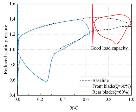
Figure 15.
Blade loading distribution of tandem rotor and Baseline rotor at 95% span.
To further reveal the influence of different meridional division positions on the internal flow mechanism of the tandem rotor, Figure 16 illustrates the loading distribution at 95% span for the front and rear blades of tandem rotors with different meridional division positions, which mainly affect the loading ratio of the front and rear of blades. When = 30% and 40% (the chord length of the rear blade is longer), the loading level of the rear blade is high. Thus, the loading distribution between the front and rear blades is not uneven. For the = 30% tandem rotor, the momentum level of the airflow is low because the positive pressure gradient acceleration section of the rear blade S.S. is shorter than the chord length. Meanwhile, because the adverse pressure gradient is highest when = 30%, the boundary layer flow separation strength of the rear blade S.S. is the most severe among all tandem configurations (Figure 14). The = 40% tandem rotor has similarities with = 30%, where the positive pressure gradient acceleration section of the rear blade S.S. is short. Subsequently, the airflow undergoes a brief deceleration after reaching the lowest static pressure level, and the static pressure level basically does not change. Then, the diffusion of the airflow quickly completes, leading to a strong adverse pressure gradient. As a result, the boundary layer flow separation strength is still more severe than that of = 50%, 60%, and 70% tandem rotors. This is also the reason why the isentropic efficiency of = 30% and 40% tandem rotors is lower than that of = 50% and 60% tandem rotors in the region above 60% span. The chord length of the front blade should not be excessively long, either. When = 70%, although the loading distribution of the rear blade is still acceptable, the adverse pressure gradient of the front blade S.S. is strong. The separation line (SL1) reappears above 60% span of the front blade, which weakens the effectiveness of using tandem rotor to inhibit the boundary layer flow separation. When = 50% and 60%, the airflow faces a moderately adverse pressure gradient after passing through the shock wave on the suction side, while the momentum level of the flow at the rear blade T.E. is high after acceleration. Therefore, the boundary layer flow separation of both the front and rear blades of the = 50% and 60% tandem rotors is significantly suppressed, resulting in high efficiency and minimal energy loss.
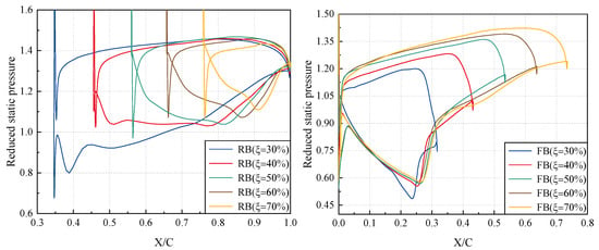
Figure 16.
Blade loading distribution of tandem rotors with different meridional division positions at 95% span.
3.2. Analysis of the Mechanism of the Circumferential Relative Position Parameter
Based on the analysis in Section 3.1, it can be concluded that the comprehensive aerodynamic performance of the = 60% tandem-rotor stage is the best among others. Therefore, the meridional division position parameter of the rotor is set to 60% in this section. And seven different tandem configurations are considered with circumferential relative positions of front and rear blades set at = 5%, 15%, 25%, 35%, 45%, 55%, and 70%. The impacts of different circumferential relative position parameters on the performance of tandem-rotor stage and the internal flow mechanism are investigated in this section.
Figure 17 presents the performance gains of PE, SM, and mchoke. According to Figure 17, the performance of the tandem-rotor stages with different circumferential relative position parameters exhibits certain patterns. The PE shows an overall trend of gradual decrease as the increases. The PE reaches its maximum when = 5% and 15%. Meanwhile, the = 70% tandem-rotor stage exhibits the lowest PE, with a difference of up to 2.14% from the maximum. In contrast to the pattern seen in PE, mchoke initially rises and then decreases as the increases. The trend of SM follows a similar pattern to that of mchoke, as it increases and then decreases with the increase in the . However, the difference is that SM always remains positive.
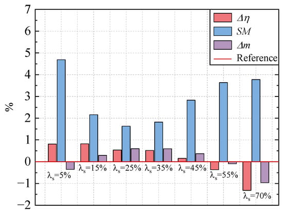
Figure 17.
Comparison of aerodynamic performance gains for tandem-rotor stages with different circumferential relative positions.
Additionally, the aerodynamic performance of Baseline and tandem-rotor stages with different circumferential relative positions at the design rotational speed is carried out, as shown in Figure 18. Obviously, the isentropic efficiency characteristics of the tandem-rotor stages exhibit significant differences. The isentropic efficiency of the = 15%, 25%, and 35% tandem-rotor stages is better than the Baseline across all stage operating conditions. For = 5% and 45% tandem-rotor stages, the isentropic efficiency is better than Baseline when stages depart from the NC. However, the isentropic efficiency of = 55% and 70% tandem-rotor stages is lower than the Baseline across all stage operating conditions. This indicates that, when the value of is small, the isentropic efficiency of the tandem-rotor stage is higher. Moreover, when the exceeds 35%, the isentropic efficiency of the tandem-rotor stage rapidly decreases. Similar to the trend in isentropic efficiency, the total pressure ratio of the tandem-rotor stage decreases as the increases. However, the total pressure ratio of the = 5% tandem-rotor stage falls between that of the = 35% and 45% tandem-rotor stages. Therefore, the values of circumferential relative position parameter should primarily be considered in the range of 5% < < 35%, while avoiding values near 70%.
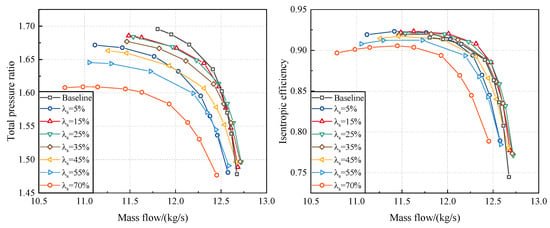
Figure 18.
Comparison of the aerodynamic performance of tandem-rotor stages with different circumferential relative positions (design rotational speed).
Based on the above analysis, it can be inferred that the different matching designs of circumferential relative positions for the front and rear blades will directly impact the aerodynamic performance of the tandem-rotor stage. Therefore, it is necessary to further analyze the aerodynamic performance variations in tandem rotors with different circumferential relative positions. Figure 19 presents the aerodynamic performance of tandem rotors with different values. Compared to the aerodynamic performance of the entire stage, the aerodynamic performance of tandem rotor does not show significant signs of choke at the NC. This once again demonstrates that the throat of the stage should be located within the stator passage. For tandem rotors with different circumferential relative positions, both the isentropic efficiency and total pressure ratio show a decreasing trend as the increases. The aerodynamic performance variation rules of the tandem rotors and tandem-rotor stages are similar. In other words, the aerodynamic performance of tandem rotor determines that of the entire stage for different values.
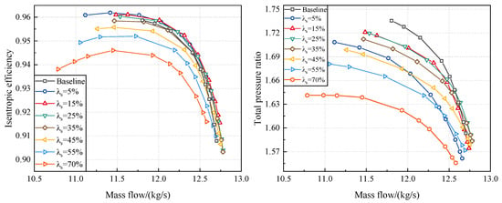
Figure 19.
Comparison of the aerodynamic performance of tandem rotors with different circumferential relative positions (design rotational speed).
Further, Figure 20 illustrates the variation in Cpt in the downstream stator. It can be observed that the Cpt in the downstream stator is at its maximum when = 70%. While for other tandem configurations, there are little differences in the Cpt values. After the stages depart from the NC, the maximum difference in Cpt for the downstream stator of the tandem-rotor stages with different values is approximately 0.015, which is not substantial. Hence, it is necessary to further analysis the performance and internal flow mechanism of tandem rotors with different values.
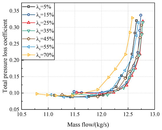
Figure 20.
Aerodynamic performance comparison of stators of tandem-rotor stages with different circumferential relative positions.
With the aim of clarifying the reasons for the differences in isentropic efficiency of tandem rotors with different circumferential relative positions, Figure 21 provides the distribution of the circumferentially averaged isentropic efficiency along spanwise at the tandem rotor and Baseline rotor outlet. When 15%, the trend of isentropic efficiency decreases as the increases in the region from approximately 30% span to the tip. Meanwhile, the isentropic efficiency difference in the region below 30% span is relatively minor. Then four representative tandem rotors with different circumferential relative positions parameters, namely 5%, 15%, 45%, and 70%, are selected to compare the differences in the distribution of isentropic efficiency variation relative to the Baseline along the spanwise. It can be observed that, in the region above 80% span to the tip, the isentropic efficiency of the tandem configurations is significantly higher than that of the Baseline. Additionally, the efficiency variation decreases as increases, with maximum efficiency improvement values at the tip region being 12.2%, 12.4%, 11.1%, and 6.4%, respectively. Nonetheless, in the region between 30% span and 80% span, there are significant differences in efficiency among tandem rotors with different circumferential relative positions. Only the = 15% tandem rotor maintains a slight efficiency edge over the Baseline at 60% span. The efficiency of = 5% tandem rotor shows comparable to the Baseline at 60% span. Both the = 55% and 70% tandem rotors exhibit lower efficiency than that of the Baseline. The efficiency gap between the highest efficiency configuration ( = 15%) and the lowest efficiency configuration ( = 70%) is approximately 3.0%. In conclusion, it is imperative to conduct a deeper analysis of the flow structures at 95% and 60% span to elucidate the underlying internal flow mechanism driving the performance disparities. Moreover, it is acknowledged that the tandem rotor exhibits certain performance variations. The subsequent study of this section is based on four representative tandem rotors with different circumferential relative parameters ( = 5%, 15%, 45%, and 70%). And a detailed analysis of their internal flow mechanism is also conducted.
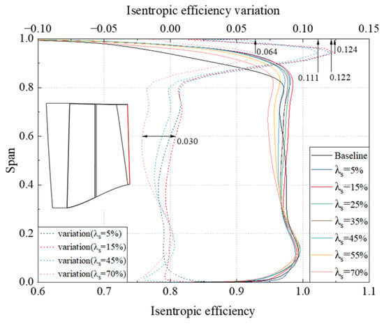
Figure 21.
Comparison of the circumferential averaged isentropic efficiency spanwise at the tandem rotors with different circumferential relative positions and Baseline rotor outlet.
Initially, to elucidate the reasons for the differences in isentropic efficiency of the tandem rotor tip region, Figure 22 illustrates the relative Mach number contour and entropy contour at 95% span. From the distribution of Mar, it can be observed that a contraction channel is formed between the front blade P.S. and the rear blade S.S. when = 5% and 15%. The throat is located at the T.E. of the front blade, where the airflow passing through this contraction channel is accelerated. The accumulation of the low-energy fluid near the front blade T.E. is inhibited. The distinct difference is that a converging–diverging channel is formed between the front blade P.S. and the rear blade S.S. The throat of the converging–diverging channel moves towards the front blade L.E. compared with that of the Baseline. The airflow passing through this converging–diverging channel accelerates first and then diffuses, causing an increase in static pressure and deceleration after the throat. In addition, it is worth noting that the interaction between the airflow from front blade and the solid wall of rear blade S.S. leads to the Coanda effect [] when the values of are small, which deflects the airflow to rear blade S.S and inhibits the wake width of the front blade significantly. Nevertheless, as increases, Coanda effect gradually disappears. As a result, the low-energy fluid accumulates at the front blade T.E. and near the rear blade P.S. when the values of are too large.
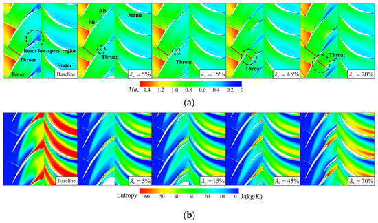
Figure 22.
(a) Relative Mach number of tandem rotors with different circumferential relative positions at 95% span. (b) Entropy of tandem rotors with different circumferential relative positions at 95% span.
From the perspective of energy loss, the implementation of the tandem rotor effectively inhibits the flow separation loss at the blade T.E. The distribution of the limiting streamlines is also more uniform than that of others and the intensity of the secondary flow is notably reduced (as shown in Figure 23). However, the extent and intensity of the high-entropy region of the front blade and rear blade are larger when = 45% and 95%. In consequence, their isentropic efficiency is lower than that of the = 5% and 15% tandem rotors. But it can still reduce the intensity of the secondary flow and achieve higher isentropic efficiency compared to the Baseline when = 45% and 95%.
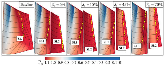
Figure 23.
Comparison of the limiting streamlines on the suction side of the tandem rotors with different circumferential relative positions.
Figure 24 illustrates the loading distribution at 95% span for the front and rear blades with different circumferential relative positions, providing a supplement to the mechanism of the above flow field variations. The loading distribution of the blades varies significantly among tandem rotors with different circumferential relative positions. While the intensity of the shock wave stays relatively consistent, the key distinctions lie in their locations. Overall, the shock wave position of the = 5%, 15%, and 45% tandem rotors remains nearly unchanged. The airflow has undergone minimal variations in the positive pressure gradient acceleration section of the front blade S.S. For the = 70% tandem rotor, the front blade S.S. acceleration section becomes shorter, and the shock wave moves closer to the front blade L.E. because the static pressure level of the front blade T.E. is high. Subsequently, the boundary layer flow with a low momentum level encounters a strong shock wave, leading to significant-scale boundary layer flow separation. Additionally, the airflow in the converging–diverging channel accelerates first and then decelerates. As a result, boundary layer flow separation is more likely to occur under the same adverse pressure gradient because the airflow momentum level near the front blade T.E. is lower than that of the = 5% and = 15% tandem configurations. For the = 45% tandem rotor, although the acceleration before the strong shock wave is sufficient, the airflow near the front blade T.E. decelerates in the diffusion section of the converging–diverging channel. Therefore, the effect to avoid boundary layer flow separation is weaker, but better than that of the = 70% tandem rotor. Moreover, for the = 45% and 70% tandem rotors, the rear section of the front blade has almost lost its ability to provide loading because the airflow near the front blade P.S. is accelerated. As for the rear blade. The airflow entering the rear blade from the front blade remains in an accelerated state when = 45% and 70%. As a result, the momentum level of the rear blade S.S. is high. However, in order to satisfy the Kutta–Joukowski condition, a significant static pressure rise is achieved at a close distance on the S.S. of the rear blade. Consequently, a strong adverse pressure gradient forms at the rear of suction side, presenting a challenge for the boundary layer flow to overcome. In conclusion, in the region of 95% span, the circumferential relative position parameter of the tandem rotor should be set to lower values to ensure higher efficiency and stronger compression capabilities.
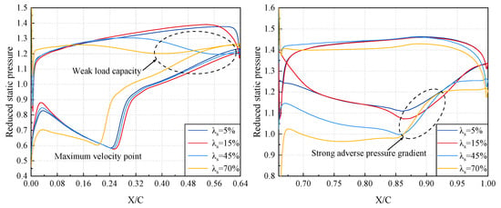
Figure 24.
Blade loading distribution of tandem rotors with different circumferential relative positions at 95% span.
Similarly, to ensure a precise understanding of the variations in isentropic efficiency near 60% span in the tandem rotor, Figure 25 illustrates the distribution of relative Mach number contour and entropy contour at 60% span of tandem rotors with different circumferential relative position parameters. Consistent with the scenario at 95% span, at 60% span, a contraction channel is formed between the front blade P.S. and the rear blade S.S. when = 5% and 15%. And the wake width of the front blade is shortened evidently when = 15% because of the Coanda effect. In contrast, a converging–diverging channel is formed between the front blade P.S. and the rear blade S.S. when = 45% and 70%. However, the key distinction is that the airflow velocity is lower at 60% span. Regardless of whether it is the Baseline or tandem rotor, the airflow velocity remains subsonic. Moreover, there is no shock wave at 60% span. As shown in Figure 25b, the energy loss at the 60% span is also minimized.
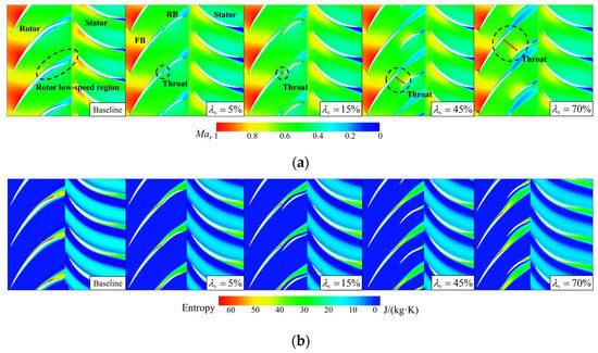
Figure 25.
(a) Relative Mach number of tandem rotors with different circumferential relative positions at 60% span. (b) Entropy of tandem rotors with different circumferential relative positions at 60% span.
For the tandem rotor, the airflow undergoes acceleration at the L.E. of the front blade and diffuses through the diffusion channel formed between adjacent front blades before entering the converging–diverging channel and the rear blade passage. As shown in Figure 26, for different tandem-rotor configuration, the airflow near the front blade S.S. reaches a similar static pressure level when it reaches maximum velocity. Subsequently, the airflow continues to decelerate and diffuse, reaching its maximum static pressure level at the T.E. of the front blade Notably, the = 70% tandem rotor exhibits the highest static pressure level near the T.E. of the front blade. In other words, the = 70% tandem rotor exhibits the strongest adverse pressure gradient. Meanwhile, the momentum level of the boundary layer flow is reduced because the airflow decelerates at the pressure side T.E. due to the converging–diverging channel between the front and rear blades. This is the reason why the strength of boundary layer flow separation is the most severe on the front blade S.S. for the = 70% tandem rotor (Figure 23). When the airflow passes through the rear blade passage, the airflow momentum level is high at the beginning for the = 40% and 70% tandem rotors (Figure 25). The airflow must achieve rapid deceleration and diffusion over a short distance on the rear portion of the S.S. to fulfill the Kutta–Joukowski condition. Similar to the situation at 95% span, the airflow struggles to overcome the strong adverse pressure gradient, resulting in significant boundary layer flow separation (Figure 23). In conclusion, near the region of 60% span, the circumferential relative position parameter of tandem rotor should also be set to a lower value to achieve positive gains in isentropic efficiency.
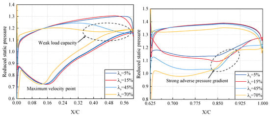
Figure 26.
Blade loading distribution of tandem rotors with different circumferential relative positions at 60% span.
3.3. Selection Criteria of Design Parameters of Tandem Rotor
In order to further summarize the design matching rules between the front and rear blades of tandem rotor, a detailed numerical simulation study is needed to investigate the coupling mechanism of the parameter and parameter on the aerodynamic performance of ultra-highly loaded single-stage compressors. Figure 27 presents the selections of various tandem rotor design parameters. In this section, five meridional division position parameters are selected: = 30%, 40%, 50%, 60%, and 70%. Additionally, at each meridional split position parameter, 14 circumferential relative position parameters are selected: = 5%, 10%, 15%, 20%, 25%, 30%, 35%, 40%, 45%, 50%, 55%, 60%, 65%, and 70%. Therefore, a total of 70 different tandem rotor design schemes were generated.
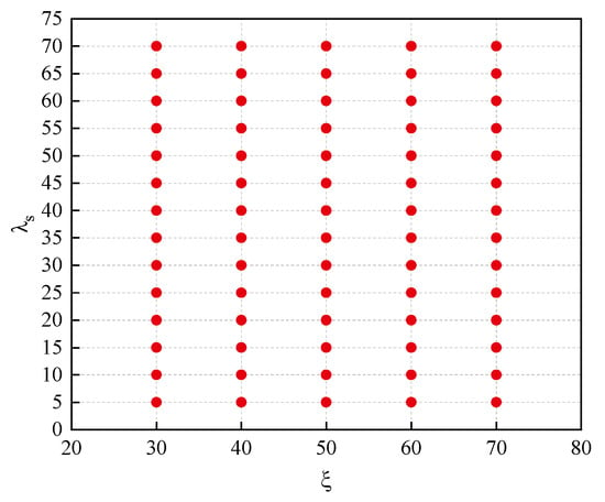
Figure 27.
Selection scheme for tandem rotor design parameters.
Figure 28 illustrates design maps of performance variations in the tandem-rotor stages with different tandem parameters. The PE of the tandem-rotor stage ranges from 87.94% to 92.40%. The difference between the maximum and minimum values is approximately 4.46%, and PE attains the maximum value when is larger and is smaller. The total pressure ratio at the PE of the tandem rotor varies from 1.609 to 1.688. The maximum value changing by approximately 4.90% relative to the minimum value, and the total pressure ratio attains the maximum value when is smaller. Meanwhile, the sensitivity of efficiency and total pressure ratio to different tandem parameters also varies significantly. Initially, when is large, the stage efficiency shows a higher sensitivity to the tandem parameter . As decreases, the sensitivity of efficiency to gradually diminishes. In contrast, the total pressure ratio is insensitive to variations in parameter . Then both the stage efficiency and total pressure ratio exhibit high sensitivity to changes in the parameter when is smaller, which indicates that the stage efficiency and total pressure ratio decrease rapidly with the increase in when is smaller. However, the declining trend of stage efficiency slows down due to the sensitivity of stage efficiency to decreases. But the sensitivity of total pressure ratio to continues to strengthen. The total pressure ratio rapidly decreases with an increase in when = 70%. Resultantly, variations in tandem parameters do not result in significant performance fluctuations near the optimal point of efficiency for the tandem-rotor stage. Conversely, variations in tandem parameters will lead to substantial fluctuations of the performance of the tandem-rotor when tandem-rotor stage performance is poor.
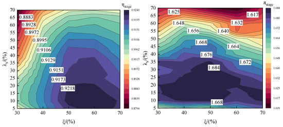
Figure 28.
Design maps of performance variations in tandem-rotor stages with different tandem parameters.
Additionally, Figure 29 illustrates the design maps of performance variations in the tandem rotors with different tandem parameters. The PE of the tandem rotor ranges from 91.52% to 96.20%. The difference between the maximum and minimum values is approximately 4.68%, and PE attains the maximum value when is large and is small. The total pressure ratio at the PE of the tandem rotor varies from 1.632 to 1.725. The maximum value changes by approximately 5.51% relative to the minimum value and attains the maximum value when and are smaller. Upon comparing the performance maps of tandem-rotor stage and tandem rotor, it becomes apparent that the trends in tandem rotor performance variations and the sensitivity of tandem rotor performance to tandem parameters are largely similar to those observed in tandem-rotor stage. This indicates that the performance of tandem rotor plays a dominant role in determining overall stage performance. However, the difference lies in the fact that tandem rotor exhibits a higher level of performance over a broader parameter selection range, indicating that tandem rotor also has an impact on the downstream stator performance. In consequence, in the application of tandem rotor technology, careful consideration should also be given to the design of downstream stator for optimal matching. In summary, it is recommended to utilize larger meridional division position parameters and smaller circumferential relative position parameters to enhance isentropic efficiency while balancing the level of total pressure ratio for the tandem rotor.
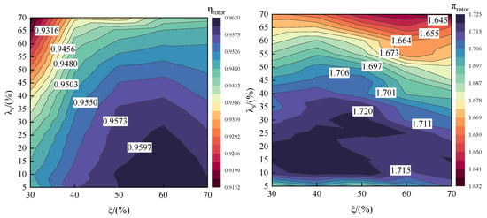
Figure 29.
Design maps of performance variations in tandem rotors with different tandem parameters.
Based on the design maps, there is an optimal tandem-rotor stage ( = 60%, = 15%) with the highest PE among 70 tandem-rotor configurations. The aerodynamic performance characteristics of the optimal tandem-rotor stage were clearly described above. We can also select new tandem parameters from the design maps to obtain a tandem-rotor stage different from the 70 tandem-rotor configurations.
4. Conclusions
This study investigated an ultra-highly loaded stage. In order to improve the isentropic efficiency of the stage, the tandem-rotor configurations with different tandem parameters were designed based on the Baseline. A comprehensive analysis was carried out on the performance disparities and internal flow mechanism of tandem rotors with various tandem parameters. The relation between the design parameters and aerodynamic performance was established. Moreover, the tandem parameters’ selection criteria of the tandem-rotor stage were refined. The key conclusions are as follows:
- It is positive for the ultra-highly loaded transonic stage to the substitute tandem rotor for the single-row rotor to inhibit the rotor boundary layer flow separation and improve the isentropic efficiency of the stage. In comparison to the Baseline, the PE improved by 0.83%, the SM increased by 2.16%, and the choke flow rate has rose by 0.30% for the optimal tandem configuration ( = 60%; = 15%). Moreover, the tandem rotor exhibits distinct capacities for enhancing isentropic efficiency along the spanwise. Above 80% span, the maximum difference in isentropic efficiency compared to the Baseline is 12.4%. Below 80% span, the isentropic efficiency changes resulting from applying tandem rotor technology typically fluctuate within a range from −0.3% to 0.8%;
- The meridional division position of rotor plays a crucial role in the aerodynamic performance of tandem rotor. The tandem rotor exhibits a superior performance when = 60% and an inferior performance when = 30%, with the PE difference of up to 1.82% between them. The primary reason for the change in performance of tandem rotors with different meridional division positions is that the loading ratio of the front and rear blades also changes. Extreme values of hinder the control over the boundary layer flow separation of the tandem rotors;
- The circumferential relative positions of the front and rear blades can have a decisive impact on the aerodynamic performance of the tandem rotor. The tandem rotor exhibits a superior performance when = 15% and an inferior performance when = 70%, with a PE difference of up to 1.96% between them. Smaller and larger values of can, respectively, cause the front and rear blades of the tandem rotor to form a contraction channel and converging–diverging channel. The former is beneficial for the performance of the tandem rotor, while the latter is detrimental. The wake width of the front blade is shortened evidently because of the Conada effect when is small;
- Our analysis of the tandem rotor design maps shows that the sensitivity of the efficiency and total pressure ratio to different tandem parameters varies significantly. Larger values of and smaller values of should be selected for the tandem rotor design to optimize both the isentropic efficiency and total pressure ratio. Additionally, the performance of the tandem rotor governs the performance of the entire stage and also affects the performance of the downstream stator. Therefore, it is important to closely consider the design of the downstream stator for optimal matching to achieve the best entire stage performance benefits when adopting a tandem-rotor configuration.
Author Contributions
Conceptualization, S.Y.; Methodology, S.Y. and Y.W.; Software, S.Y. and Y.W.; Formal analysis, S.Y. and Y.W.; Investigation, X.L. and G.H.; Data curation, Y.W.; Writing—original draft, S.Y.; Writing—review & editing, S.Z., X.L. and G.H.; Visualization, S.Y. and S.Z.; Supervision, S.Z.; Project administration, G.H.; Funding acquisition, X.L. and G.H. All authors have read and agreed to the published version of the manuscript.
Funding
This research was funded by Science Center for Gas Turbine Project, P2022-B-II-003-001; the National Major Science and Technology Project of China, Y2022-II-0003-0006; and Youth Innovation Promotion Association CAS, No. 2023153.
Data Availability Statement
The authors confirm that the data supporting the findings of this study are available within the article.
Conflicts of Interest
The authors declare no conflict of interest.
Nomenclature
| meridional division position parameter of the tandem rotor | |
| circumferential relative position parameter of the tandem rotor | |
| flow angle to axial direction | |
| AO | axial overlap of the tandem rotor |
| circumferential displacement angle between the forward and rear blades | |
| the axial gap between the front and rear blades | |
| C | chord length of the blade |
| PE | peak efficiency |
| SM | stall margin |
| mchoke | flow rate at the choke point |
| L.E. | leading edge of the blade |
| T.E. | trailing edge of the blade |
| NC | near stall point |
| NS | near choke point |
| P.S. | pressure side of the blade |
| S.S. | suction side of the blade |
| N(b,e) | the number of blades |
| Mar | relative Mach number |
| Pre | reduced static pressure |
| Cpt | total pressure loss coefficient |
| Pt | total pressure |
| Ps | static pressure |
| y+ | nondimensional wall distance of the first node |
| SL | separation line |
| change percentage of the mchoke | |
| change percentage of the mchoke | |
| turning angle, | |
| peak efficiency of the Baseline | |
| peak efficiency of the tandem-rotor stage | |
| total pressure ratio of the Baseline at the NC | |
| total pressure ratio of the tandem-rotor stage at the NC | |
| peak efficiency of the tandem-rotor stage | |
| peak efficiency of the tandem rotor | |
| total pressure ratio of the tandem-rotor stage at PE | |
| total pressure ratio of the tandem rotor at PE |
References
- Biollo, R.; Benini, E. Recent Advances in Transonic Axial Compressor Aerodynamics. Prog. Aerosp. Sci. 2013, 56, 1–18. [Google Scholar] [CrossRef]
- Song, D.J.; Hwang, H.C.; Kim, Y.I. A Numerical Study of Shock Wave/Boundary Layer Interaction in a Supersonic Compressor Cascade. KSME Int. J. 2001, 15, 366–373. [Google Scholar] [CrossRef]
- Denton, J.D. Loss Mechanisms in Turbomachines. Trans. Asme J. Turbomach. 1993, 115, 621–656. [Google Scholar] [CrossRef]
- Railly, J.W. An Investigatiqn of the Flow through Tandem Cascades. In Proceedings of the Institution of Mechanical Engineers, Conference Proceedings; Sage: London, UK, 1965; Volume 180, pp. 66–73. [Google Scholar] [CrossRef]
- Bammert, K.; Beelte, H. Investigations of an Axial Flow Compressor with Tandem Cascades. J. Eng. Power 1980, 102, 971–977. [Google Scholar] [CrossRef]
- Saha, U.K.; Roy, B. Experimental Investigations on Tandem Compressor Cascade Performance at Low Speeds. Exp. Therm. Fluid Sci. 1997, 14, 263–276. [Google Scholar] [CrossRef]
- Mcglumphy, J.; Saad, A.; Wellborn, S.R. Numerical Investigation of Subsonic Axial-Flow Tandem Airfoils for a Core Compressor Rotor. Magic Ritual Witch. 2008, 3, 104–109. [Google Scholar] [CrossRef]
- McGlumphy, J.; Ng, W.-F.; Wellborn, S.R.; Kempf, S. Numerical Investigation of Tandem Airfoils for Subsonic Axial-Flow Compressor Blades. J. Turbomach. 2009, 131, 021018. [Google Scholar] [CrossRef]
- McGlumphy, J.; Ng, W.-F.; Wellborn, S.R.; Kempf, S. 3D Numerical Investigation of Tandem Airfoils for a Core Compressor Rotor. J. Turbomach. 2010, 132, 031009. [Google Scholar] [CrossRef]
- LIU, B.; ZHANG, C.; AN, G.; FU, D.; YU, X. Using Tandem Blades to Break Loading Limit of Highly Loaded Axial Compressors. Chin. J. Aeronaut. 2022, 35, 165–175. [Google Scholar] [CrossRef]
- Mao, X.; Wang, Y.; Ding, Z.; Cheng, H.; Liu, B. Design Criteria of Load Split and Chord Length Ratio for Highly Loaded Compressor Tandem Cascades. Phys. Fluids 2024, 36, 026117. [Google Scholar] [CrossRef]
- Luo, Q.; Luo, L.; Song, X.; Du, W.; Yan, H.; Wang, S.; Zhou, X. Effects of Curved Vanes on Aerodynamic Performance and Flow Structures in Highly Loaded Tandem Cascades. Phys. Fluids 2024, 36, 036114. [Google Scholar] [CrossRef]
- Zhang, B.; Mao, X.; Liu, B.; Wang, H.; Yang, Z. Complicated Flow in Tip Flow Field of a Compressor Tandem Cascade Using Delayed Detached Eddy Simulation. Chin. J. Aeronaut. 2024, in press. [Google Scholar] [CrossRef]
- Clemmons, D. Single-Stage Experimental Evaluation of Tandem-Airfoil Rotor and Stator Blading for Compressors. Part 2: Data and Performance for Stage A; NASA: Washington, DC, USA, 1972.
- Eshraghi, H.; Boroomand, M.; Tousi, A.M. Design and Analysis of a Highly Loaded Tandem Compressor Stage. In Proceedings of the ASME 2014 International Mechanical Engineering Congress and Exposition, Montreal, QC, Canada, 14–20 November 2014; American Society of Mechanical Engineers Digital Collection. American Society of Mechanical Engineers: New York, NY, USA, 2015. [Google Scholar] [CrossRef]
- Kumar, A.; Pradeep, A.M. Performance Evaluation of a Tandem Rotor Under Design and Off-Design Operation. In Proceedings of the ASME Turbo Expo 2018: Turbomachinery Technical Conference and Exposition, Oslo, Norway, 11–15 June 2018. [Google Scholar] [CrossRef]
- Kumar, A.; Pradeep, A. Design and Off-Design Behavior of a Tandem Rotor Stage. Proc. Inst. Mech. Eng. Part G J. Aerosp. Eng. 2020, 234, 927–942. [Google Scholar] [CrossRef]
- Kumar, A.; Pradeep, A.M. Response of a Tandem Staged Compressor to Circumferential Inflow Distortion. J. Fluids Eng. 2022, 144, 091202. [Google Scholar] [CrossRef]
- Kumar, A.; Chhugani, H.; More, S.; Pradeep, A.M. Effect of Differential Tip Clearance on the Performance of a Tandem Rotor. J. Turbomach. 2022, 144, 081007. [Google Scholar] [CrossRef]
- Kumar, A.; Kumar, A.; Pradeep, A.M. Spike Type of Stall Inception in the Tandem Rotor. ARCHIVE Proc. Inst. Mech. Eng. Part C J. Mech. Eng. Sci. 2022, 236, 10413–10425. [Google Scholar] [CrossRef]
- Hasegawa, H.; Matsuoka, A.; Suga, S. Development of Highly Loaded Fan with Tandem Cascade. In Proceedings of the 41st Aerospace Sciences Meeting and Exhibit, Reno, NV, USA, 6–9 January 2003; American Institute of Aeronautics and Astronautics: Reno, NV, USA, 2003. [Google Scholar] [CrossRef]
- Burger, G.D.; Keenan, M.J. Single-Stage Evaluation of Highly-Loaded High-Mach-Number Compressor Stages. 3-Data and Performance Tandem Rotor; NASA: Washington, DC, USA, 1970.
- Sakai, Y.; Matsuoka, A.; Suga, S.; Hashimoto, K. Design and Test of Transonic Compressor Rotor with Tandem Cascade. In Proceedings of the International Gas Turbine Congress, Tokyo, Japan, 2–7 November 2003. [Google Scholar]
- Mohsen, M.; Owis, F.M.; Hashim, A.A. The Impact of Tandem Rotor Blades on the Performance of Transonic Axial Compressors. Aerosp. Sci. Technol. 2017, 67, 237–248. [Google Scholar] [CrossRef]
- Liu, B.; Wang, G.; An, G.; Yu, X. Experimental and Numerical Study on Tip Leakage Flow of Highly Loaded Tandem Rotor. J. Eng. Thermophys. 2023, 44, 332–341. [Google Scholar]
- Zhou, S.; Zhao, S.; Zhou, C.; Wu, Y.; Yuan, H.; Lu, X. Optimal Design and Analysis of a High-Load Supersonic Compressor Based on a Surrogate Model. Aerospace 2023, 10, 364. [Google Scholar] [CrossRef]
- Zhang, H.; Wang, H.; Li, Q.; Jing, F.; Chu, W. Mechanism Underlying the Effect of Self-Circulating Casings with Different Circumferential Coverage Ratios on the Aerodynamic Performance of a Transonic Centrifugal Compressor. Aerospace 2023, 10, 312. [Google Scholar] [CrossRef]
- Li, X.; Dong, J.; Chen, H.; Lu, H. The Control of Corner Separation with Parametric Suction Side Corner Profiling on a High-Load Compressor Cascade. Aerospace 2022, 9, 172. [Google Scholar] [CrossRef]
- Zhang, L.; Wang, S.; Zhu, W. Application of Endwall Contouring in a High-Subsonic Tandem Cascade with Endwall Boundary Layer Suction. Aerosp. Sci. Technol. 2019, 84, 245–256. [Google Scholar] [CrossRef]
- Huang, S.; Zhou, C.; Yang, C.; Zhao, S.; Wang, M.; Lu, X. Effect of Backward Sweep on Aerodynamic Performance of a 1.5-Stage Highly Loaded Axial Compressor. In Proceedings of the ASME Turbo Expo 2020: Turbomachinery Technical Conference and Exposition, Virtual, Online, 21–25, September 2020; American Society of Mechanical Engineers Digital Collection. American Society of Mechanical Engineers: New York, NY, USA, 2021. [Google Scholar] [CrossRef]
- Tao, Y.; Wu, Y.; Yu, X.; Liu, B. Analysis of Flow Characteristic of Transonic Tandem Rotor Airfoil and Its Optimization. Appl. Sci. 2020, 10, 5569. [Google Scholar] [CrossRef]
- Reba, I. Applications of the Coanda Effect. Sci. Am. 1966, 214, 84–93. [Google Scholar] [CrossRef]
Disclaimer/Publisher’s Note: The statements, opinions and data contained in all publications are solely those of the individual author(s) and contributor(s) and not of MDPI and/or the editor(s). MDPI and/or the editor(s) disclaim responsibility for any injury to people or property resulting from any ideas, methods, instructions or products referred to in the content. |
© 2024 by the authors. Licensee MDPI, Basel, Switzerland. This article is an open access article distributed under the terms and conditions of the Creative Commons Attribution (CC BY) license (https://creativecommons.org/licenses/by/4.0/).