Abstract
Large-caliber and long-barrel weapons are important experimental devices for exploring the impact resistance and reliability of warheads. The force of impact of the muzzle jet has a significant influence on the overload resistance of the warhead and surrounding devices. The mechanism of motion of the body inside the tube cannot be ignored owing to the high kinetic energy at the muzzle. In this study, we designed the relevant experiment and a simulation model to analyze the structural characteristics and mechanism of evolution of the shock wave and the vortex structure in a muzzle jet. The aim was to examine the evolution of the shock wave with initial jet-induced interference. And we established three other simulation models to compare the similarities and differences between the results of the models. The results showed that, in the original complex model, the initial jet restricted the free expansion of the muzzle jet, and this led to many shock–shock collisions that retarded the development of the shock waves. Multiple reflected shock waves were thus formed under a high local pressure that distorted the shock structure, while the structure of the shock wave in the simplified models was clear and simple. The parameters of motion of the body changed by a little when the initial jet-induced interference was ignored. The difference in values of the strongest impact force measured at monitoring points far from the muzzle was small, with an error of about 2%, such that the simplified model without the initial jet could be used in place of the original complex model. The other simplified models yielded significant differences. Our results provide an important theoretical basis for further research on the muzzle jet and its applications in engineering.
1. Introduction
When a barrel weapon launches a projectile, the muzzle flow field will cause initial disturbance to the projectile’s flight, reducing its shooting accuracy and increasing its impact point dispersion. In addition, with the development of large-caliber high-initial-velocity artillery, a series of problems such as muzzle flame, muzzle smoke, muzzle shock wave, and noise have emerged, further increasing the initial disturbance of the projectile. Therefore, studying the influence of muzzle flow field on the flight stability of projectiles is one of the important issues in weapon science research. The mechanism of operation of the muzzle jet is a challenging issue at the intersection of multiple disciplines, including gas dynamics, aerodynamic acoustics, and chemical dynamics [1,2]. The moving body accelerates and compresses the air in front of it under the propulsion of gunpowder gas in the tube to form the initial jet. The harmful disturbance caused by the muzzle jet of a large-caliber weapon launcher is extremely strong [3,4]. Due to the presence of the flame, smoke, and electromagnetic interference in the muzzle, it is difficult to measure and calculate the structure of the shock wave in a transient muzzle jet [5,6]. This makes it important to examine the muzzle jet by using numerical simulations.
Past research has provided a clear understanding of the mechanism of development of the muzzle jet as well as the law of distribution of the shock wave at the muzzle and the aftereffect of muzzle flow on moving bodies [7]. Research on the muzzle jet has benefited from advances in computational technologies and methods of numerical calculation. Merlen et al. [8] conducted theoretical analysis based on experimental observations to obtain the law of similarity of the flow field of the muzzle. Ma [9,10] considered the influence of the moving body to analyze the disturbance induced by it on the flow field in calculations of the muzzle jet. Jiang [11] used a structured grid to simulate the muzzle jet of a 122 mm caliber vehicle-mounted gun and analyzed the flow occurring during the launch of a moving body with an initial velocity of 713 m/s. Dai [12,13] numerically simulated the combustion-induced flow field of a body with an initial velocity of 735 m/s with a brake inside a muzzle with a diameter of 7.62 mm. The authors used control equations of the three-dimensional (3D) unsteady flow of the chemical reaction to describe the structure and properties of the flow field of the muzzle as well as its interactions with the moving body. Florio [14] used the 2D axisymmetric Navier–Stokes (N–S) equation and the k-ε turbulence model to simulate the flow field of a muzzle device with a side hole containing a cylindrical moving body. Jiang [15] used the ALE equation and dynamic grid technology to simulate the entire process of motion of the body from inside a 44 mm caliber bore to outside it until it flew away from the initial flow field. Guo [16,17] considered a 7.62 mm ballistic gun for an experimental analysis of the initial flow field at the muzzle and its aftereffects based on the ALE equation and a partition-structured body-fitted grid. Zhang [18] used the 3D Euler equation in combination with the Roe scheme and structured dynamic grid technology to numerically simulate the flow field at the muzzle of a 20 mm caliber gun with a brake. Schmidt et al. [19,20] measured a group of characteristic parameters of the muzzle brake structure on a 20 mm small-caliber gun using the time-accumulated shadow photography technology, obtained a clearer image of the muzzle jet, and analyzed the characteristics and flow mechanism of the muzzle jet. He observed that the coupling between the flow fields in the axial direction was very strong but the coupling along the transverse direction was very weak. Combined with the dynamic grid technology, Zhang [21] established a two-dimensional axisymmetric numerical simulation model to numerically study the explosion flow field generated by the supersonic jet. It is confirmed that the interaction between precursor shock and bow shock is closely related to the velocity of the projectile.
Previous research in the area has mostly focused on analyzing the characteristics of gas jets by using small-caliber short-barrel guns and has not adequately analyzed the interference of the initial jet. We know even less about its potential role in the characteristics of the shock wave and the vortex in the muzzle jet of a 300 mm large-diameter long-barrel launch weapon.
We use a long-barrel and large-caliber launch device as the object of research in this study. Given the structural configuration of such an experimental device, it is difficult to accurately describe the complete characteristics of its muzzle jet by using numerical simulations.
The first model of our research is the actual, whole, original complex model. This involves the movement of the body inside the tube, its movement outside the muzzle, the initial interference jet formed by the compression of gas inside the tube, and the gas muzzle jet formed by the high-temperature and high-pressure gunpowder gas injected after the moving body. All these factors also interfere with one another to form a complete muzzle jet.
The second model of our research here is that we construct simplified 3D models for analysis. It ignores the initial interference jet but includes the motion of the body outside the muzzle and the gas muzzle jet formed by the injection of gunpowder gas. This makes the physical model simpler, reduces the mesh size, and eliminates the need for coupling between dynamic meshes inside and outside the tube to significantly reduce the workload.
The third model of this study is one that neglects the model of the moving body but includes the initial interference jet formed by the gas being squeezed out of the bore as well as the gas jet formed by gunpowder gas. The lack of use of dynamic grid technology during the simulation significantly simplifies the establishment of the model.
The fourth model of our work here is a simplified model that ignores the moving body and the initial jet and considers only the free injection of the gas muzzle jet. This physical model is the simplest of the ones considered here and significantly reduces the size of the mesh.
Based on this large-barrel weapon device, the purpose of this paper is to restore its real complex three-dimensional structure characteristics of the muzzle jet by establishing a complete numerical simulation model. By comparing the simplified model, it is confirmed whether the simplified model is replaceable in some aspects. Therefore, we establish reasonable mathematical and physical models, use them to conduct experiments and numerical simulations, and provide a detailed examination of the structural characteristics of the muzzle jet, the mechanism of evolution of shock waves and vortices, changes in the parameters of the moving body, and the energy distribution of the muzzle jet.
2. Model of Numerical Simulation
2.1. Equations and Turbulence Model
Without considering the effect of external heating and body force, three-dimensional, time-dependent unsteady compressible Navier–Stokes equations are used as the governing equations:
where Q is the vector of the conservative variables and f, g, and h are the vectors of the convective flux. They are expressed as:
where:
The total energy per unit flow is expressed as:
where p is the pressure, ρ is the gas density, u, v, and w are the velocity components of the fluid, and γ is the gas specific heat ratio. The ideal gas state equation is , where R is the universal gas constant and μ is the laminar viscous coefficient. τxx, τxy, τxz, τyx, τyy, τyz, τzz, τzx, and τzy are the viscous forces of different directions; k is the heat conductivity and qx, qy, and qz are the volumetric heating rates in unit mass.
The realizable k-ε turbulence model is applied in the article. Compared to the stand and k-ε turbulence model, it has two main differences: 1. realizable k-ε model adds a formula for turbulent viscosity; 2. a new transfer equation has been added for the dissipation rate. Introducing Boussinesq’s linear eddy viscosity assumption, the Reynolds stress expression is:
Different eddy viscosity models have varying eddy viscosity coefficients in the model:
where:
The normal stress in the realizable k-ε model is . The Schwarz inequality for Reynolds shear stress is:
2.2. Model of Physical Structure
We considered a 300 mm test launch device. It contained a moving body that traveled in a tube with a diameter of 300 mm at the muzzle and a wall with a thickness of 50 mm. The moving body was a simplified cylinder that weighed 160 kg and was 600 mm long. Numerically simulating such a device is a challenging problem as it needs to be simplified while ensuring a certain accuracy. We established a total of four sets of models (four cases; see Table 1) as follows:

Table 1.
Characteristics of the models.
Case 1 involved the complete structure shown in Figure 1a. It featured a moving body, a 30 m long tube, and the domain around the muzzle. Case 2 ignored the motion of the body inside the tube, as shown in Figure 1b, and considered only its motion outside the muzzle. Case 3 ignored the moving body altogether, as shown in Figure 1c, and involved only the initial jet and the muzzle jet. In Case 4, the motion of the body inside and outside the bore was ignored, as shown in Figure 1d, and only the domain outside the muzzle was considered. The flow field was 10 m long along the direction of motion of the body (X-axis), including 3 m toward the rear of the muzzle, and was 8 m long in the other two directions (Y-axis and Z-axis), as shown in Figure 1a.
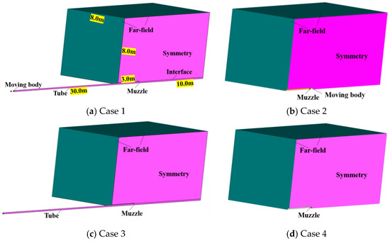
Figure 1.
Schematic diagram of the model of the physical structure.
2.3. Grid Model
A widely accepted technique is to consider only a quarter of the physical model, rather than the entire model, to reduce computational time and cost. The entire computational domain was divided into structural grids, as shown in Figure 2. Case 1 featured 11 million grids, while each of the other three models had 9 million grids. Mesh refinement is applied near the muzzle and projectile, while it is relatively rough at the boundary of the computational domain. The minimum size of the mesh near the muzzle is 0.2 mm and the mesh growth rate is 1.05. When simulating complex flow fields, it is often difficult to generate a single high-quality structural mesh. In this case, the mesh can be partitioned and concatenated for processing. We thus divided the computational domain into domains with static and dynamic grids and used their interface for numerical exchange.

Figure 2.
Schematic diagram of grid model of the muzzle jet of a large-caliber long-barrel launcher.
2.4. Boundary Conditions and Solution Methods
We used models of the interior ballistics and aftereffects as well as a model with six degrees of freedom for secondary development in FLUENT software (Fluent19.2) and numerically simulated the complete model of the large-caliber long-barrel muzzle jet.
Figure 3 shows the types of boundaries used. Specifically, the pressure outlet was used as the boundary of the calculation domain, with an environmental pressure of 101,325 Pa and a temperature of 300 K. The tube was set to be a nonslip adiabatic wall, while the moving wall was set for the moving body. Its motion was controlled by a ballistics model inside the tube and by a six-degrees-of-freedom program (six-DOF) after it had exited the muzzle. The pressure inlet was set for the muzzle and it was controlled by using a UDF program. Experimental measurements and those of the internal ballistics model yielded a muzzle pressure of 24.4 MPa and a temperature of 2000 K. According to the model of the aftereffects of the launch device, the variation in the muzzle pressure over time was p = 24.4 × 10−24.886t MPa.
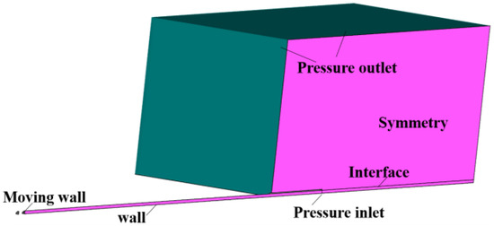
Figure 3.
Schematic diagram of boundary conditions.
In addition, we processed the motichenon in the given block-based division of the mesh based on the finite volume method in combination with the structural dynamic method. The Navier–Stokes (N–S) equation solver based on density correction and the k-ε realizable turbulence model were used. The inviscid convective flux was split by using the Roe-FDS scheme, and the implicit scheme was used with the time marching method to accelerate the convergence of the numerical calculations. The equation of flow control was discretized by using the second-order upwind scheme, and the material was assumed to be an ideal gas. The time step used in this article was initially 1 * 10−7, then gradually increased to 1 × 10⁻⁶, with 50 iterations.
2.5. Models of Interior Ballistics and Aftereffects
Specifically, the internal ballistic model is as follows:
where:
where ψ1 is the percentage of main charge burned, μ1 is the burning rate coefficient of main charge, e1 is the thickness of the main charge, and ρ is the density of the gas powder. fb is the ignition powder, ρg is the average density of gunpowder gas in the chamber, and χ1, λ1, and μ1 are the characteristics of the shape of the main charge gunpowder. k is the adiabatic index, ld is the travel of the projectile, and lp is the travel of the balance body. ωb is the charge quality of ignition powder, m1 is the mass of the projectile, m2 is the mass of the balance body, ω1 is the quality of the main charge, φ is the secondary power coefficient, n is the burning rate index, φ1 is the flow correction factor, pd is the bottom pressure of the projectile, φd is the drag coefficient of the bottom of the projectile, pp is the bottom pressure of the balance body, φp is the drag coefficient of the bottom of the balance body, p1 is the pressure in the tube, s is the area of the tube, Z1 is the relative thickness of the main charge that has been ignited, vd is the velocity of the projectile, vp is the velocity of the balance body, V1 is the pharmacy volume, and Vψ is the free volume of pharmacy.
The aftereffect model is as follows:
where s is the area of the muzzle and v0 is the velocity of the projectile when it reaches the muzzle. k is the specific heat ratio of gunpowder gas and pg is the pressure of the muzzle.
Then, we compiled these models using C language and the language rules that UDF needs to follow, forming the UDF program. We use the UDF program to control the motion of the projectile inside the tube, as well as the initial conditions of the muzzle during the aftereffect period. The parameters corresponding to a conventional launch were obtained through an interior ballistics model as the initial boundary conditions for the numerical calculation of the muzzle jet, as shown in Table 2. The changes in pressure and velocity at the bottom of the tube are shown in Figure 4a,b. And we inferred that the variations in pressure in the muzzle over time were p = 24.4 ×e−24.668t MPa [22,23,24]. This enables us to achieve numerical simulation of the development and evolution of shock waves throughout the entire process of projectile motion.

Table 2.
Results of calculation of internal ballistics.
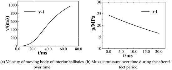
Figure 4.
Velocity of the moving body under the effect of the muzzle pressure over time in the models of interior ballistics and aftereffects.
To achieve control of the projectile’s motion throughout the entire process from its initial motion to its flight away from the muzzle, it is necessary to solve the coupled solution process of fluid control equations and rigid body dynamics equations. The motion law of a projectile is determined by the aerodynamic load it receives, and the distribution of the aerodynamic load can be determined by solving the flow field. Therefore, a rigid body six-degree-of-freedom dynamic equation system is established, including the motion equation of the rigid body’s center of mass and the motion equation system of the rigid body around the center of mass. The system of six-degree-of-freedom motion differential equations for a rigid body can be expressed as:
Among them, V is the flight speed of the projectile; θa is the velocity elevation angle (also known as ballistic inclination angle); ψ2 is the velocity direction angle (also known as the trajectory deviation angle); ωϛ, ωɳ, and ωξ are the rotational angular velocity of the projectile; φa is the high and low angle of the projectile axis (also known as the high and low swing angle); φ2 is the direction angle of the projectile axis (also known as the directional swing angle); γ is the roll angle; x, y, and z are the spatial co-ordinates of the projectile (horizontal distance, trajectory height, and lateral deviation); Vx, Vy, and Vz are the three components of the projectile’s flight speed (horizontal velocity, vertical velocity, and lateral velocity); t is the flight time. Fx2, Fy2, and Fz2 are the three components of all combined forces acting on the projectile in the ballistic co-ordinate system. Mϛ, Mɳ, and Mξ are the three components of all resultant moments acting on the projectile in the axis co-ordinate system; m is the mass of the projectile; A is the equatorial moment of inertia; C is the polar moment of inertia; δ2 is the directional attack angle; δ1 is the high and low angle of attack, which is the angle between the first axis co-ordinate system and the second axis co-ordinate system; kcx is the coefficient of conformity for resistance; kmz is the coefficient of conformity for static torque.
The above model is a six-degree-of-freedom rigid body trajectory equation for projectile motion, with a total of 15 variables and 15 equations. The equation system is closed and can be solved using numerical calculation methods. When the structural parameters, aerodynamic parameters, shooting conditions, meteorological conditions, and starting conditions of the projectile are known, the motion law of the projectile and the trajectory data at any time can be obtained by integration.
2.6. Dynamic Mesh Method
Dynamic meshing technology has been widely used to handle changes in the mesh caused by the motion of a rigid body during calculations, as shown in Figure 5. Commonly used dynamic grid algorithms include layering, smoothing, and local remeshing. Given that we assume here that the body moves only in one direction, the layering method can be used to simulate the motion of the rigid body. The dynamic layering method is a very effective method in dealing with the deformation of stretched mesh, which can handle changes in grid topology, add or remove nodes in the grid, and is very suitable for situations with large motion amplitude. It determines whether to split or merge the grid based on the height of the grid connected to the detection motion boundary and the combined effect of the set splitting factor (Cs), collapse factor (Cl), and grid height reference value (hi). The dynamic layering method includes a height-based dynamic layering method and ratio-based dynamic layering method, both of which have the same principles for grid splitting and merging but have differences in the height of the generated grid. The application of the dynamic layering method is limited to three-dimensional hexahedral meshes and two-dimensional quadrilateral meshes, and it requires high quality of meshes.
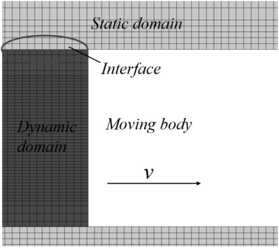
Figure 5.
Schematic diagram of the boundary conditions of the model of the muzzle jet.
It requires setting the segmentation and merging factors of the grid. The grid moves forward along the X-axis after the moving body. A layer of the grid near the tail of the moving body is elongated, with a side length of hs. Part of the grid that exceeds the boundary of the computational domain is truncated, and its length near the boundary of the computational domain is hc. Assuming that the ideal grid size is hi, the grid is divided into two parts when the newly generated grid size satisfies h > (1 + Cs) hi. Moreover, when the grid size satisfies h > Cshi, the grid merges into one. In this example, hi = 2.0 mm, Cs = 0.4, and Cl = 0.2.
2.7. Grid Independence Verification
To verify the independence of the grid, we designed three sets of girds, namely 6.0 million, 11 million, and 14 million. They were, respectively, called Coarse grid, Fine grid, and Dense grid. Regarding the variation in a monitoring point (2000, 1000, and 0) mm in Case 4, Figure 6 demonstrates the results of numerical simulations of the different grid models considered. In this article, the region where the moving body moves is set as the moving region, while the other regions are the stationary region, meaning that the mesh is not moving. In this article, the region where the moving body moves is set as the moving region, while the other regions are the stationary region, meaning that the mesh is not moving. The dynamic region in the text is relatively small, and most of it is still a static region. For this reason, using the pressure change at a monitoring point as a grid independence verification can also demonstrate that the calculation results in this article are grid-independent. From the figure, it can be seen that the results of fine and dense grids were very close, with an error of less than 1%. But there were significant differences in the results obtained by the Coarse gird model. It can be concluded that, when using the Fine grid model, the simulation results were independent of the size of the gird.
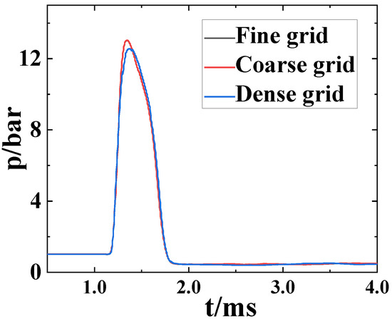
Figure 6.
Pressure comparison of a monitoring point to verify grid independence.
3. Experiments
3.1. Test Equipment and Plan
The launch device used here was a test platform for weapons launch with a large caliber and a long barrel, as shown in Figure 7. The device had a diameter of 300 mm, a thickness of the wall of 50 mm, and a total distance of 30 m traveled by the moving body. A schematic diagram of the model is shown in Figure 8. The height between the ground and the muzzle is 2.2 m. Vp means the velocity of the moving body and Vb means the velocity of the balance body. The balance body is a part of the experimental apparatus and an important component for achieving the function and performance of the test, but it is not related to the model in this article. The front half of the tube is the running section of the projectile, called the projectile tube. In the middle of the tube is the chamber, and behind the chamber is the section of the balance body called the balance object tube.
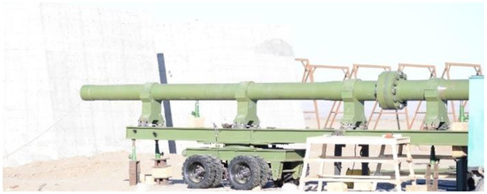
Figure 7.
Structure of the launch test device for large-diameter barrel weapons.

Figure 8.
Schematic diagram of launch test device for a weapon with a large caliber and a long barrel.
The experimental plan considered here is shown in Figure 9. The test bench was the main launch device that pushed the moving body out of the muzzle at a speed of 932.0 m/s. The moving body flew forward after exiting the muzzle. Dynamic pressure sensors were installed at key points on both sides of its flight trajectory to monitor changes in transient pressure in the flow field. A piezoelectric dynamic pressure sensor was used to obtain the transient pressure at characteristic points in the overpressure field. All pressure signals were collected by using a DEWE2-A13 transient data recorder, produced by DEWETRON Industrial Equipment Company in Graz, Austria, with a sampling frequency of 500 kHz. We chose KISTLER-6215 and KISTLER-211B4 (Winterthur, Switzerland) pressure sensors for experimental pressure testing. Among them, the maximum range of the KISTLER-6215 sensor is 6000 bar, used to measure pressure changes in the tube and at the muzzle, while KISTLER-211B4 sensor is 500 psi, used to measure pressure changes in the flow field. And a Photon high-speed camera was used to capture images of the formation and development of the overpressure field. During the experiment, the ignition system ignited the gunpowder inside the chamber to produce high-temperature and high-pressure gas, which drove forward the moving body at a high speed. The high-speed camera was also used to capture the developmental posture of the muzzle jet and the movement-related posture of the moving body as well as to calculate its speed. We simultaneously triggered the pressure sensors to monitor the pressure at the characteristic points.
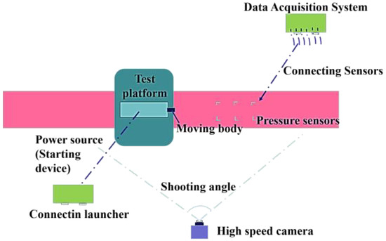
Figure 9.
Schematic diagram of test scheme.
3.2. Experiment Results
The high-speed camera recorded the dynamic characteristics of the launch device, and obtained the development and structural characteristics of the supersonic muzzle jet. Owing to the large amount of charge required to launch the body and its high kinetic energy, the gunpowder burned negatively in the chamber and underwent secondary combustion after being ejected from the muzzle. The resulting muzzle flame made it difficult to determine the shape of the shock wave. As shown in Figure 10a, the moving body traveled at a high speed inside the tube, pushing the air in front of it to form compression waves. These compression waves continuously propagated toward the muzzle but did not spread to it. Figure 10b,c show that the air in the front of the moving body was squeezed out of the muzzle to form the initial jet. The sprayed gas rapidly expanded, resulting in a decrease in pressure and an increase in velocity, and diffused into the environment. The wave front of the initial jet was approximately spherical, with a weak impact force that was one order of magnitude smaller than that of the subsequent gunpowder-induced gas jet. At this point, a small amount of gas leaked from the gap between the moving body and the tube to form a small area of the flame at the muzzle.

Figure 10.
Development of the supersonic muzzle jet over time.
Figure 10d shows that, when the moving body left the tube, the high-temperature and high-pressure gunpowder gas inside the tube was quickly sprayed out to chase and surround the moving body. The flow field of the gunpowder gas had a spherical structure. A large amount of gunpowder and gas was sprayed out of the muzzle, causing secondary combustion and forming a large area of high-temperature turbulent combustion. As the projectile moved, the muzzle jet could not surround it, and they gradually separated. A unique shear layer was formed on the side of the moving body, starting at its head and then extending outward from its side. Because the velocity of the gas ejected from the muzzle exceeded that of the moving body, a clear shock wave was formed at its bottom.
Changes in the pressure at key points were also monitored during the test. Figure 11 compares the curves of pressure versus time between the test and the simulation at the point (3000, 500, and 200 mm), and it is clear that they were consistent. Specifically, the center point of the muzzle is defined as the origin. The X-axis represents the direction of projectile motion, with the Y-axis perpendicular to the X-axis pointing upwards and the Z-axis perpendicular to the XY plane pointing sideways. Therefore, the method of simulation used in this paper could accurately simulate the characteristics of the muzzle jet of the models.
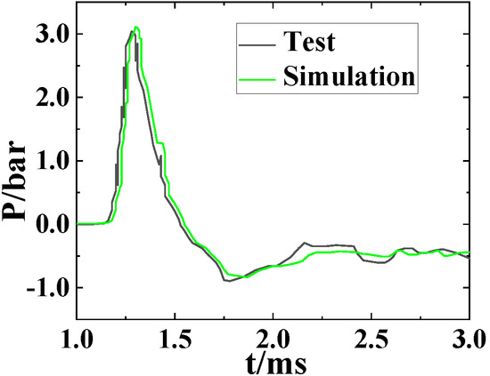
Figure 11.
Comparison of the changes in pressure over time at a key point between the test and the simulation.
4. Results of Numerical Simulations
We analyze the evolution of the morphology of the shock wave in the gas jet and its role in enhancing the mixing process in order to describe the strong unsteady characteristics of 3D flow and mechanism of mixing of the gas jet with interference by the initial jet. The muzzle jet with initial interference was complicated as it involved such phenomena as collisions between shock waves, those between shock waves and vortices, and collisions between vortices. This led to the development of reflected and focused shock waves. The complexity of the structural features of the shock waves decreased significantly in three of the simplified models considered here. We focus here on (1) the analysis and comparison on the characteristics of the muzzle jet in the four models on the plane of symmetry, including the mechanism of evolution of the morphology of the shock wave and changes in the morphology of the vortex, (2) analysis and comparison of the 3D morphology of the shock waves, (3) comparison of changes in pressure and velocity over time at the key feature points, and (4) comparison of the parameters of motion of the body.
4.1. Structure of Flow Field
We used the physical model and the model of interior ballistics to determine that, driven by the propellant gas in the tube, the moving body moved for 68.5 ms within the tube before reaching the muzzle. Figure 12 shows the pressure of the initial interference jet formed by compressed air in front of the moving body in the inner tube over time (from 63 ms to 68 ms). As shown in Figure 12a, the initial jet was about to form at 63 ms and the velocity of the moving body was 913.6 m/s at this time. At 63 ms, the moving body is moving inside the tube and the shock wave before it has reached the muzzle. At this point, the initial flow field is about to form and the moving body is 6.5 m away from the muzzle, with a velocity of 901.8 m/s. The pressure at which the shock wave before the projectile reaches the muzzle is approximately 1.1 MPa. Figure 12b–e show that, as the moving body continued to accelerate, the air in front of it was compressed out of the muzzle. The air rapidly expanded, the pressure decreased, and the velocity of the body increased to form the initial jet, including bow-induced shock waves (BS), Mach disks (MD), and bottle shock waves (BoS) (shown in Figure 12f). The body had moved out of the muzzle by 68.5 ms, at which point its velocity was 932 m/s.

Figure 12.
Changes in the pressure of the initial jet over time.
Figure 13 shows the pressure (0.5 ms~10.0 ms) over time in Case 1 (the model with interference by the initial jet) on the plane of symmetry. As shown in Figure 13a, the initial jet had already influenced the area around the muzzle at t = 0.5 ms. High-temperature and high-pressure gas was sprayed out of the muzzle with the movement of the body, expanded rapidly with a reduction in pressure and an increase in velocity, and continuously diffused toward the surrounding area. The coronal shock wave (CS) in front of the moving body encountered the bottle-shaped shock wave (BoS) of the initial jet, leading to a shock–shock collision that led to the disappearance of the CS of the moving body. The structure of the BoS of the initial jet was also destroyed, and it was replaced by two reflected shock waves (RS). The MD of the initial jet was compressed and deformed and led to the formation of the spherical shock wave (SS) of the muzzle jet.
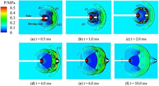
Figure 13.
Changes in the pressure of the muzzle jet over time in Case 1.
As shown in Figure 13b, the body continued to move forward and the muzzle jet continued to eject gas at t = 1.0 ms. The deformed CS in front of the moving body encountered the MD of the initial jet, causing a shock–shock collision. The MD of the initial jet disappeared and the CS did not form. Instead, two RSs were generated, and the SS of the muzzle jet was clearly visible. It was slightly deformed due to interference from the initial jet. We also observed that a clear shock wave appeared at the bottom of the moving body because the high-temperature and high-pressure gas jet expanded at a much higher rate than the velocity of the moving body. It expanded more quickly under the influence of the initial jet. The muzzle jet encountered the moving body such that this suppressed its development and led to a reflection in the shock wave and a change in its direction of propagation. The muzzle jet continuously sprayed out gas, and the forward-moving shock wave collided with the reflected shock wave to suppress its development. The reflected shock wave was thus stopped and formed a “horizontal” shock wave at the bottom of the moving body.
Figure 13c shows that the body continued to move forward while the muzzle jet continued to spray gas. All shock waves except for the BoS of the initial jet had been quelled by this time, and the BoS of the muzzle jet was formed. Due to the suppression of the development of the SS in the muzzle jet by the surface of the outermost SS of the initial jet, the BoS of the muzzle jet caught up with the SS to yield a shock–shock collision. This led to the formation of multiple RSs that were sufficient to disrupt the shape of the SS and distort the BoS.
Figure 13d shows that the structure of the shock wave of the muzzle jet gradually became clear and the moving body was about to cross the area surrounding the initial jet. A CS gradually formed in front of the moving body, and the BoS and MD gradually became clear. The SS of the muzzle jet was still twisted and deformed due to the limitation of the initial jet and the impact of the BoS. As is shown in Figure 13e, the moving body had completely broken through the hood of the initial jet at t = 6.0 ms, but the initial jet still had a slight impact on the muzzle jet. Although the development of the shock waves was dependent on their history, they formed a complete muzzle jet including the CS, BoS, MD, bottom shock waves of the moving body, and SS.
Figure 13f shows that the shadow of the initial jet was not visible at t = 10.0 ms, and the entire area was filled with jets from the high-temperature and high-pressure gunpowder gas. A complete muzzle jet was thus formed. Although there were some differences between this state and that without interference from the initial jet, the influence of the latter gradually disappeared.
Figure 14 shows changes in the pressure (0.5 ms~10.0 ms) in Case 2 (the model without interference by the initial jet) on the plane of symmetry over time. Due to the absence of interference by the initial jet, the structure of the muzzle jet was more regular than that in Case 1. The body moved forward at a high speed to form a CS at the front. The high-temperature and high-pressure gas was sprayed behind the moving body, rapidly expanded at a speed above 1900 m/s, and chased and impacted the body to form shock waves at its bottom and on both sides of it. The moving body gradually freed itself from the impact of the muzzle jet and flew forward at a high speed. At this point, a complete muzzle jet was formed containing a CS, BoS, MD, bottom shock waves of the moving body, and an SS.

Figure 14.
Changes in the pressure of the muzzle jet over time in Case 2.
The above results show that the main difference between Cases 1 and 2 was that the speed of expansion of the muzzle jet was lower in the latter case due to the absence of interference by the initial jet, and the degree of enclosure of the moving body weakened to cover only half of its length. The structure of the muzzle jet was clear and distinct, without complex shock–shock collisions or the formation of an additional reflected shock wave. The shape of the muzzle jet was smooth and followed a regular pattern over time. However, under interference from the initial jet, there was no consistent pattern of development of the shock wave in the first 4 ms. The structure of the muzzle jet followed a certain pattern of development until the interference by the initial jet had been completely eliminated.
Figure 15 shows changes in the pressure (0.5 ms~10.0 ms) in Case 3 (the model without the projectile but with interference by the initial jet) on the plane of symmetry. The development of the shock wave was similar to that in Case 1. Under interference by the initial jet, the high-temperature and high-pressure gunpowder gas was sprayed out and encountered the BoS of the initial jet for a shock–shock collision to form two reflected RSs. Following this, the muzzle jet encountered the MD of the initial jet to form a local area of high pressure and two RSs. The muzzle jet continued to develop, and a complete jet was subsequently formed that contained a CS, BoS, MD, bottom shock waves of the moving body, and an SS.

Figure 15.
Changes in the pressure of the muzzle jet over time in Case 3.
Figure 16 shows changes in pressure in Case 4 (the model without either the projectile or interference by the initial jet) over time on the plane of symmetry. It clearly shows the typical shock wave of the muzzle jet. High-temperature and high-pressure gas was sprayed out of the nozzle, expanded rapidly to reduce the pressure and increase the velocity, and diffused in a 3D symmetrical manner in the surroundings. The phenomenon of a complete wave system consisting of shock waves, including SSs, RSs, and an MD with overlapping discontinuities, has been widely observed.

Figure 16.
Changes in the pressure of the muzzle jet over time in Case 4.
4.2. Structure of the Vortex
The muzzle jet disturbed by the initial jet featured not only shock–shock collisions but also shock–vortex and vortex–vortex interactions. To comprehensively analyze the characteristics of flow in a muzzle jet with interference by the initial jet, we monitored the temporal changes in the vortices as shown in Figure 17a, which shows that the vortex of the initial jet still existed at t = 1.0 ms and was symmetrical. The vortex was located in the low-pressure region, with the streamline pointing from the center to the outside, while the spiral point was stable. As shown in Figure 17c, the strong shock wave of the muzzle jet encountered the weak vortex of the initial jet at t = 2.0 ms and caused it to disappear. A vortex behind the flow field was formed and gradually became clear, as shown in Figure 17d,e.

Figure 17.
Changes in the streamlines of the muzzle jet over time in Case 1.
The vortex in Case 2 was relatively simple and clear (as shown in Figure 18) and was formed at around t = 2.0 ms. Due to the absence of interference from the initial jet, the vortex persisted in the low-pressure area, with its streamline pointing from the center to the outside and the spiral point being stable. Compared with Case 1, Case 3 lacked a coupling of the moving body, while its impact on the collision between shock waves and vortices was minor. We can conclude that the development and evolution of vortices in Case 3 were similar to those in Case 1 (as shown in Figure 19).

Figure 18.
Changes in the streamlines of the muzzle jet over time in Case 2.

Figure 19.
Changes in the streamlines of the muzzle jet over time in Case 3.
4.3. Structure of the Shock Wave
To fully capture the interference by the initial jet in the shock wave of the muzzle jet, Figure 20 shows a schematic diagram of the shock wave in Case 1 at different times. Figure 20a shows that the outermost spherical shock wave of the initial jet surrounded the complex shock wave inside. The muzzle jet was ejected and encountered the shock wave of the initial jet to yield strong shock–shock collisions, shock–vortex collisions, and vortex–vortex collisions that hindered the expansion of the shock wave and formed an area of local high pressure. As shown in Figure 20b, the shock wave of the muzzle jet, which was disturbed by the initial jet, remained complex over time. The spherical shock wave of the muzzle jet broke through the wave front of the spherical shock of the initial jet, and the two wave fronts collided to arrest the expansion of the shock wave and form an area of local high pressure. The bow shock in front of the moving body had already appeared at this time. Figure 20c shows that, as the muzzle jet developed at t = 8.0 ms, the influence of the initial jet almost disappeared and the shock wave gradually became clear and simple.

Figure 20.
Development of the shock wave in Case 1.
Figure 21 shows a schematic diagram of the structure of the shock wave at different times in Case 2. The structure of the shock wave of the muzzle jet was clearer and simpler than in Case 1. The bow shock bent on both sides around the shear layer of the jet in 3D space, forming a spherical shock wave front that enveloped the other shock wave structures inside. A flow field composed of cylindrical shock waves, MDs, and RSs was formed in a highly under-expanded jet basin.

Figure 21.
Development of the shock wave in Case 2.
4.4. Parameters of the Moving Body
Figure 22 and Figure 23 show a comparison of the parameters of the moving body (such as its resistance and lift) over time between Cases 1 and 2. The impact force and the velocity of the moving body were different between the models. Because the initial jet had already disturbed the area in front of the muzzle in Case 1, the pressure in this area was lower than the ambient pressure. When the high-temperature and high-pressure gas was sprayed out, it led to a higher ratio of a drop in pressure compared with the model without disturbance from the initial jet. This accelerated the expansion of the gas. The high-speed gas impacted the bottom of the moving body, causing it to be subject to a greater impact force (as shown in Figure 22a). The velocity of the moving body was also slightly higher than that in Case 2 (as shown in Figure 22b), but this difference was not large enough to have a significant impact on a moving body with an initial velocity of 1000 m/s or higher. We can infer that the resistance experienced by the moving body was also higher than in Case 2 (as shown in Figure 23a). The muzzle jet disturbed by the initial jet involved several shock–shock and shock–vortex collisions that added to the complexity of the flow field. The high-pressure and low-pressure regions alternated, resulting in an unstable lift on the moving body compared with that in Case 2.
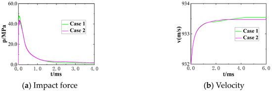
Figure 22.
Comparison of the impact force and velocity of the moving body.
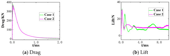
Figure 23.
Comparison of the resistance and lift of the moving body.
Table 3 shows errors in the parameters of the moving body in the two models (Cases 1 and 2). When a large-caliber weapon and a projectile with a high kinetic energy were used, errors in the drag and lift of both models were about 2.5%, the error in the thrust was about 9%, while the error in velocity was the smallest at 0.01%. These results provide a reference for the analysis of numerical simulation for engineering applications.

Table 3.
Errors in the parameters of motion of the body in Cases 1 and 2.
4.5. Pressure Comparison of Key Points
To better understand the pressure distribution in the muzzle jet when it was disturbed by the initial jet, we monitored the changes in pressure over time at several key points. Figure 24 is a schematic diagram of the distribution of pressure at these points and Table 4 shows their locations (with the muzzle as the center).
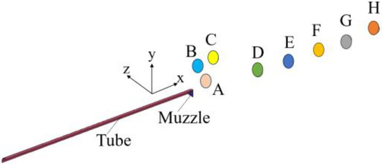
Figure 24.
Distribution of feature points.

Table 4.
Positional parameters of the feature points.
Figure 25 shows a comparison of the changes in static pressure over time at various monitoring points. We sought to determine whether the simplified models (Cases 2–4) could attain the same accuracy as the original model (Case 1) for engineering applications. It is clear from the figure that the changes in pressure in Cases 2 and 4 were the simplest and clearest. That is, when the shock wave passed a given monitoring point, the pressure at it increased and then decreased. Slightly more complex scenarios were encountered in Cases 1 and 3 due to interference from the initial jet. The fluctuations in pressure at the monitoring points near the muzzle were significant and similar. Figure 25a,c show that, due to the proximity of the monitoring point to the muzzle, the latter was located in the region of the expansion wave of the initial jet, and the pressure here was lower than the ambient pressure. Therefore, the pressure of the muzzle jet at the initial moment in Cases 1 and 3 was lower than the ambient pressure (i.e., less than zero relative to the ambient pressure). The monitoring points shown in Figure 25b were not disturbed by the initial jet, because of which the initial pressure at this point in all four models was identical to the environmental pressure. The two monitoring points in Figure 25d,e were located in the high-pressure zone of the initial jet, because of which the pressure at these points was higher than the ambient pressure. The three monitoring points shown in Figure 25f–h were located far from the muzzle such that they were unaffected by the initial jet, and thus their initial pressure was the ambient pressure. The changes in pressure at monitoring points near the muzzle in Cases 1 and 3 were similar because they were severely affected by the initial jet and the effect of coupling of the moving body was not strong. At several monitoring points far from the muzzle, the changes in pressure in Cases 1 and 2 were similar, as the muzzle jet had already separated from interference by the initial jet and was influenced only by its coupling with the moving body.
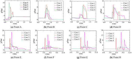
Figure 25.
Comparison of pressure at the monitoring points in the four cases.
Figure 26 shows a comparison of the changes in the velocity of the moving body over time at each monitoring point. It is clear that the velocity exhibited the same trend as the static pressure over time at each monitoring point. At monitoring points near the muzzle, the changes in velocity in Cases 1 and 3 over time were similar, as both cases involved the initial jet and the effect of coupling of the moving body was not strong. Changes in velocity in Cases 1 and 2 at several monitoring points far from the muzzle were similar because the flow had already separated from interference by the initial jet and was influenced only by the coupling between the muzzle jet and the moving body.


Figure 26.
Comparison of velocity at the monitoring points in the four cases.
Taken together, our findings indicate that, under the working conditions considered here—that is, a muzzle pressure of 25 MPa, an initial velocity of the moving body of 900–1000 m/s, a static pressure near the muzzle of approximately to 10–20 atm, and a dynamic pressure of around 20 atm—the muzzle jet without interference from the initial jet (Case 2) was a good choice as a simplified model of calculation beyond a distance of 5 m. When considering a location close to the muzzle, the muzzle jet subjected to interference by the initial jet but without a moving body (Case 3) is suitable as a simplified model of calculation. This solves the problem of the difficulty of simulating the muzzle jet of a large-caliber and long-barrel launcher.
5. Conclusions
In this study, we examined the characteristics of development of shock waves and vortices in a muzzle jet in case of interference by the initial jet for a launch device with a large diameter and a long barrel with a high kinetic energy of the muzzle. The conclusions are as follows:
- (1)
- The shock wave of the muzzle jet under interference by the initial jet was complex and featured shock–shock collisions and shock–vortex collisions in the flow field that suppressed the expansion of the muzzle jet and led to the formation of multiple reflected shock waves and high-pressure zones. The strong shock wave of the muzzle jet collided with the weak vortex of the initial jet, causing it to disappear and leading to the formation of a stable vortex of the muzzle jet in the flow field. The muzzle jet without interference by the initial jet had a clear and simple structure.
- (2)
- Owing to the low energy of the initial jet—one order of magnitude lower than the energy of the muzzle jet—the force of its impact on the high-speed moving body was relatively small, while the impact on its lifting force was relatively large but could be ignored.
- (3)
- If the distance to the muzzle is not considered under the operating conditions considered here, the muzzle jet without the initial jet-induced interference can be used as a simplified model for calculation beyond a distance of 5 m. When considering a location close to the muzzle and ignoring the moving body, the muzzle jet under interference by the initial jet can be used as a simplified model for calculation.
Author Contributions
Conceptualization, Z.L. and H.W.; methodology, Z.L.; software, Z.L.; validation, Z.L.; formal analysis, Z.L.; investigation Z.L.; resources, Z.L.; data curation, Z.L.; writing—original draft preparation, Z.L.; writing—review and editing, Z.L.; visualization, Z.L.; supervision, H.W.; project administration, H.W.; funding acquisition, H.W. All authors have read and agreed to the published version of the manuscript.
Funding
This research received no external funding.
Data Availability Statement
All data and models that support the findings of this study are available from the corresponding author upon reasonable request. All data and models generated or used during the study appear in the submitted article.
Acknowledgments
Thank you to Hexia Huang (Nanjing University of Aeronautics and Astronautics) for his opinions, guidance, and contributions to this article.
Conflicts of Interest
The authors declare that they have no conflicts of interest.
References
- Li, Z.; Wang, H.; Chen, J. Ground effects on the hypervelocity jet flow and the stability of projectile. Eng. Appl. Comput. Fluid Mech. 2018, 12, 375–384. [Google Scholar] [CrossRef]
- Chaturvedi, E.; Dwivedi, R.K. Computer aided design and analysis of a tunable muzzle brake. Acta Armamentarii 2019, 015, 89–94. [Google Scholar] [CrossRef]
- Jiang, S.Y.; Wang, H.; Lin, C.J.; Wang, J.L. Establishment and simulation of two-dimensional interior ballistics model of large caliber Davis gun considering the axial movement of tubular charge clusters. Acta Armamentarii 2016, 37, 1941–1948. [Google Scholar]
- Schmidt, E.M.; Shear, D. Optical measurements of muzzle blast. AIAA J. 2012, 13, 1086–1091. [Google Scholar] [CrossRef]
- Wang, G.; Cheng, C.; Zhang, X.; Huang, X. Numerical simulation and analysis of muzzle flow during a rarefaction wave gun firing. Propellants Explos. Pyrotech. 2021, 46, 45–46. [Google Scholar] [CrossRef]
- Zhao, X.Y.; Zhou, K.D.; He, L.; Lu, Y.; Wang, J.; Zheng, Q. Numerical simulation and experiment on impulse noise in a small caliber rifle with muzzle brake. Shock Vibr. 2019, 12, 1–12. [Google Scholar] [CrossRef]
- Moumen, A.; Grossen, J.; Ndindabahizi, I.; Gallant, J.; Hendrick, P. Visualization and analysis of muzzle flow fields using the background-oriented schlieren technique. J. Vis. 2020, 23, 409–423. [Google Scholar] [CrossRef]
- Merlen, A.; Dyment, A. Similarity and asymptotic analysis for gun-firing aerodynamics. J. Fluid Mech. 1991, 225, 497–528. [Google Scholar] [CrossRef]
- Ma, D.W. Calculation of unsteady flow field containing moving objects. Explos. Shock 1991, 11, 31–36. [Google Scholar]
- Ma, D.W.; Le, G.G.; Yu, S.H. Numerical simulation of supersonic free jet with insufficient expansion. J. Comput. Phys. 1994, 11, 362–366. [Google Scholar]
- Jiang, K.; Wang, H.; Huang, M. Numerical simulation of the firing flow field of a gun with muzzle brake. Int. Symp. Ballist. 2010, 22, 51–53. [Google Scholar]
- Dai, S.L.; Xu, H.Q. Numerical simulation of three-dimensional detonation waves induced by high-speed flying projectiles. Propuls. Technol. 2007, 28, 3. [Google Scholar]
- Dai, S.L.; He, Z.D.; Xiao, Z.L. Numerical simulation of combustion flow field at the muzzle of negative oxygen balanced propellant. J. Explos. Explos. 2011, 34, 3. [Google Scholar]
- Florio, L.A. Effect of vent opening area and arrangement on gas flow field as gas propelled cylinder exits a flow tube. Meccanica 2010, 45, 475–501. [Google Scholar] [CrossRef]
- Jiang, X.; Chen, Z.; Fan, B.; Li, H. Numerical simulation of blast flow fields induced by a high-speed projectile. Shock Waves 2008, 18, 205–212. [Google Scholar] [CrossRef]
- Guo, Z.; Jiang, X.; Wang, Y. Parallel numerical simulation of muzzle reacting flow. Chin. J. Comput. Mech. 2013, 30, 111–116+123. [Google Scholar]
- Guo, Z.; Qiao, H.; Jiang, X. Numerical simulation on the characteristics of flow field of the muzzle of embedded aircraft gun. Acta Armamentarii 2017, 38, 2373–2378. [Google Scholar]
- Zhang, H.; Xiao, Y.; Zheng, C.; Chen, Z.; Xue, D.; Zhu, S.; Song, W. Characteristics of three-dimensional flow field structure of supersonic transverse jet. J. Propul. Technol. 2023, 44, 30–39. [Google Scholar]
- Schmidt, E.M.; Fansler, K.S.; Shear, D.D. Trajectory Perturbations of Fin-Stabilized Projectiles Due to Muzzle Blast. J. Spacecr. Rocket. 2015, 14, 339–344. [Google Scholar] [CrossRef]
- Schmidt, E.M.; Gordnier, R.E.; Fanslert, K.S. Interaction of Gun Exhaust Flowfields. AIAA J. 1984, 22, 516–517. [Google Scholar] [CrossRef]
- Zhang, X.B. Gun Ballistics; Beijing Institute of Technology Press: Beijing, China, 2014. [Google Scholar]
- Jiang, Z.; Takayama, K.; Skews, B.W. Numerical study on blast flow fields induced by supersonic projectiles discharged from shock tubes. Phys. Fluids 1998, 10, 277–288. [Google Scholar] [CrossRef]
- Li, Z.J.; Wang, H. Effect of Precursor Flow Field of Muzzle on the Combustion Gas Jet Flow of Gun Propellant. Chin. J. Energetic Mater. 2017, 25, 282–290. [Google Scholar]
- Jin, Z.M. Advanced Internal Ballistics; Higher Education Press: Beijing, China, 2003. [Google Scholar]
Disclaimer/Publisher’s Note: The statements, opinions and data contained in all publications are solely those of the individual author(s) and contributor(s) and not of MDPI and/or the editor(s). MDPI and/or the editor(s) disclaim responsibility for any injury to people or property resulting from any ideas, methods, instructions or products referred to in the content. |
© 2024 by the authors. Licensee MDPI, Basel, Switzerland. This article is an open access article distributed under the terms and conditions of the Creative Commons Attribution (CC BY) license (https://creativecommons.org/licenses/by/4.0/).