Article

Aerodynamic Characteristics of the Novel Two-Dimensional Enhanced Shock Vector Nozzle

1
School of Aeronautics, Northwestern Polytechnical University, Xi’an 710072, China
2
Aerospace Technology Institution, China Aerodynamic Research and Development Center, Mianyang 621000, China
*
Author to whom correspondence should be addressed.
Aerospace 2024, 11(5), 369; https://doi.org/10.3390/aerospace11050369
Submission received: 17 March 2024 / Revised: 26 April 2024 / Accepted: 1 May 2024 / Published: 7 May 2024
(This article belongs to the Section Aeronautics)

Abstract

:
Fluid thrust vectoring (FTV) control has obvious advantages in structural quality and stealth performance because of its fast response and light weight. However, improving FTV vector performance will cause a loss in engine performance due to the need to draw airflow from the engine. In order to alleviate the above problems and further improve the vector performance of FTV, a nozzle combined with throat skewing and shock vector control is proposed, and the secondary flow of the nozzle comes from the throat and is injected into the nozzle divergence section. The numerical results indicate that compared with the original configuration, the vector angle and vector efficiency of the new configuration are more linear with the nozzle pressure ratio (NPR), and the vector angle and vector efficiency are improved by 163% and 218%, respectively, while experiencing a maximum reduction in the thrust coefficient of 1.4%. Compared with the only bypass-type shock vector nozzle, the new configuration utilizes the diversion of the two jets to eliminate the reattachment of the separation bubble after the jet and its resulting abrupt change in vector performance, improving the performance while having good control characteristics. Additionally, a sensitivity analysis of the spacing between two jets is also carried out. The spacing between two jets should be increased to make the flow pass through two weaker shock waves to improve the vector performance while ensuring that the separation after the jet is no longer attached.

1. Introduction

Thrust vectoring technology has become one of the key technologies for advanced fighter aircraft as a means to significantly improve the maneuverability, agility, and survivability of the vehicle [1,2]. Currently, mechanical thrust vectoring is the prevalent method, which has been successfully applied to the F22 and SU35. However, this technology increases both the weight and maintenance costs of the aircraft. Critically, the seams inherent in mechanical devices adversely affect the stealth capabilities of these vehicles [1,3].
The fluidic thrust vectoring (FTV) method deflects the primary flow by secondary flow and primary flow interference and is considered a highly promising control method because of its fast response, light weight, and stealth performance [3,4,5]. NASA [6] first conducted research on the use of FTV for aviation and developed four control methods such as shock vector control (SVC), co-flow control, counter-flow control, and throat skewing or the double throat nozzle (DTN). The fluidic oscillators [7] can be regarded as another kind of FTV that has not been applied. Figure 1 shows a schematic diagram of the typical FTV methods. The DTN achieves a higher vector angle and thrust coefficient, but the control at the throat results in a smaller discharge coefficient for the nozzle. A large number of experimental and numerical studies have been carried out for the DTN method, and an in-depth understanding of its characteristics has been obtained. However, when the nozzle changes from a convergent nozzle to a convergent–divergent nozzle and the NPR increases, the performance of the DTN decreases significantly [8,9,10,11,12,13]. The counter-flow [1,14] method has excellent performance in terms of the thrust coefficient, vector angle, and discharge coefficient. However, how to arrange the negative pressure source reasonably in the engine is a problem that needs to be solved. Otherwise, the counter-flow method has to face the risk of blocking the secondary flow orifice. In addition, for the co-flow and the counter-flow methods, the convex-curved surfaces, namely Coanda surfaces, are usually extended on the upper and lower surfaces behind the nozzle outlet. These surfaces facilitate airflow adherence due to the Coanda effect, and the maximum deflection angle of airflow attached to the wall is related to the curvature of the Coanda surface. However, the presence of Coanda surfaces introduces significant bi-stability [5] and hysteresis issues [15,16], which are detrimental to flight control.
Due to its straightforward installation and implementation, the shock vector control (SVC) method is readily applicable in engineering practice [17]. This method involves injecting the high-pressure secondary flow into the nozzle’s divergence section, which interferes with the primary flow to form a shock wave. This interaction, combined with the entrainment effects of the secondary flow and the shock wave, generates counter-rotating separation bubbles in front of the secondary flow, leading to a pressure differential across the upper and lower surfaces of the nozzle. The primary flow then deflects through this shock wave, altering the vector angle and enhancing vector thrust. The effects of the NPR, secondary pressure ratio (SPR), and geometrical parameters on the performance of the SVC nozzle have been explored by a series of experiments and numerical studies [18,19,20,21,22,23,24,25,26,27]. The vector angle of an SVC nozzle increases monotonously in the absence of shock reflection within the nozzle or when the reflected shock does not strike the opposite wall. Conversely, as the intensity of the shock wave increases, there is a rise in flow loss within the nozzle, resulting in a reduction in the thrust coefficient. Increasing the SPR also leads to an increase in the separation range before the jet, which further increases the vector angle. However, indiscriminately increasing the SPR can induce shock reflection within the nozzle and raise the secondary flow rate, imposing more stringent demands on the engine. The NPR is another aerodynamic parameter that mainly affects the performance of the SVC nozzle, and it determines the expansion state of the nozzle (the momentum of the primary flow). Because of its working principle, the SVC nozzle has a remarkable effect in the over-expansion state. With an increase in the NPR, the primary flow momentum increases, the range and intensity of the high-pressure zone before the secondary flow decrease, and the separation and reattachment even occur after the secondary flow, which leads to a decrease in the thrust vector angle of the nozzle, but the thrust coefficient increases. The jet’s position and jet angle are the key geometric parameters [25,26,27]. The jet near the nozzle outlet and opposite to the primary flow is helpful in improving the vector performance of the SVC nozzle with less thrust loss [27].
No matter which control method is used, the secondary flow mainly comes from the compressor of the engine, and the increase in the secondary flow rate not only increases the vector angle but also reduces the performance of the engine. In order to alleviate or even eliminate the engine performance degradation caused by the secondary flow, researchers proposed bypassing the DTN [28,29,30], bypassing the SVC method [31,32,33], and other new methods [34]. Combined with the previous ideas, we propose an enhanced shock vector control nozzle (ESVC), which has the characteristics of both throat skewing and the SVC method. The primary flow of this nozzle is led out from the throat and injected into the divergence section, and can be used alone or together with the secondary flow from the compressor to control the vector performance of the SVC nozzle. The ESVC further improves the vector performance of the SVC without increasing the bleed flow from the engine. In the remaining part, firstly, the numerical method is introduced and verified. Secondly, the design concept and specific geometric parameters of the ESVC are explained. Finally, the vector performance of the ESVC in different states and different geometric parameters is studied and compared with the original SVC (OSVC), and its advantages are analyzed.

2. Numerical Method

2.1. Flow Solver

The simulations were conducted using the in-house solver PMB3D, a Reynolds-averaged thin-layer Navier–Stokes (RANS) flow solver designed for multi-block structured grids. This solver addresses the time-independent RANS equations, employing a cell-centered finite volume approach on multi-block structured grids. The inviscid fluxes within the RANS framework can be calculated using either van Leer or Roe’s schemes; for the purposes of this paper, Roe’s scheme is selected. The monotone upstream-central scheme for conservation laws (MUSCL) interpolation method ensures second-order accuracy, while viscous fluxes are handled through second-order central differencing. An implicit approach, specifically the lower–upper symmetric Gauss–Seidel (LU-SGS) method, facilitates time advancement. To enhance convergence, techniques such as the multigrid method and grid sequencing are implemented. The turbulence modeling is comprehensive, incorporating the one-equation Spalart–Allmaras (SA) model, the two-equation shear stress transport (SST) model, and their modified counterparts (SA-RC, SST-RC, et al.). PMB3D has been successfully applied to a variety of problems, including internal flow [35], wing flow [36], and missile launches [37], consistently yielding favorable outcomes.

2.2. Governing Equations

The governing equations in this paper are the RANS equations. These equations include the conservation of mass, momentum, and energy, as given by Equations (1)–(3)
ρ t + x i ρ u i = 0
t ρ u i + x i ρ u i u j = p x i + x j μ u i x j + u j x i 2 3 δ i j u k x k + x j ρ u i u j
t ρ E + x i u j ρ E + p = x j k T T x j + x j u j μ u i x j + u j x i 2 3 δ i j u k x k i , j , k = 1 , 2 , 3
where ρ represents the fluid density, and u , p , T and μ represent the mean velocity, pressure, temperature, and the dynamic viscosity, respectively. For the energy Equation (3), E represents the specific internal energy and k T represents the thermal conductivity. The ρ u i u j denotes Reynolds stress, which must be solved by the turbulence model. The air is assumed as an ideal gas with a specific heat ratio γ of 1.4 and satisfies the ideal state equation as follows:
p = ρ R T
where R = 287.058 J / k g · K is the gas constant. The selection of the SST turbulence model is justified by its great performance in flows, characterized by the shock-induced boundary layer separation, as observed in the SVC nozzle. Consequently, the SST model, as delineated in Equations (5) and (6), is employed to close the RANS equations.
( ρ k ) t + ( ρ u j k ) x i = P k β * ρ ω k + x j μ + σ k μ t k x j
( ρ ω ) t + ( ρ u j ω ) x i = γ P ω β ρ ω 2 + x j μ + σ ω μ t ω x j + 2 ρ 1 F 1 σ ω 2 ω k x j ω x j
where k, ω , μ t are the turbulence kinetic energy, the specific dissipation rate, and the turbulence viscosity, respectively. For the detailed introduction of the SST model, along with the comprehensive definitions and values of each parameter, readers are directed to reference [38]. The parameters of the SST model employed in this study are consistent with those outlined in the aforementioned literature. Owing to the full turbulence calculations, a turbulence level of 1% is maintained across all the simulations presented in this paper.

2.3. Definitions of Nozzle Performance Parameters

The common parameters used to evaluate the performance of FTV nozzles are as follows: thrust coefficient, pitch vector angle, yaw vector angle, pitch thrust vector efficiency, and yaw vector efficiency. In this paper, a two-dimensional nozzle is studied, so both the vector angle and the vector efficiency are considered in the pitch direction only. The parameters and the required variables are defined as follows.
The isentropic thrusts of the primary flow and secondary flow are defined as follows:
F i , m = ω m × 2 γ R γ 1 × 1 N P R γ 1 γ × T t , m 1 2 F i , s = ω s × 2 γ R γ 1 × 1 N P R × S P R γ 1 γ × T t , s 1 2
where NPR and SPR denote the ratio of the total pressure of the primary flow to the ambient pressure of the nozzle and the ratio of the total pressure of the secondary flow to the total pressure of the primary flow, respectively. The ω m and ω s denote the primary and secondary flow mass flow rates, respectively. T t , m and T t , s denote the total temperature of the primary and secondary flows.
The actual thrust is calculated as the sum of the momentum force and pressure force:
F = ρ V Δ A · V + p p · Δ A
where Δ A , p, ρ , V , and p , denote the nozzle outlet area, nozzle outlet pressure, density, velocity, and ambient pressure, respectively.
The thrust coefficient is defined as the ratio of actual thrust to the sum of the isentropic thrust of the primary flow and secondary flow:
C f g = F / F i , m + F i , s
The vector angle in the pitch direction is the ratio of the normal force to the axial force at the nozzle outlet. In this paper, the vertical downward direction is the positive direction of the vector angle:
δ p = arctan ( F z / F x )
The vector efficiency represents the vector angle caused by a 1% secondary flow rate:
η p = δ p 100 × ω s / ω m %
In the vector angle and vector efficiency, the subscript p denotes the pitch direction.

2.4. Computational Domain and Boundary Conditions

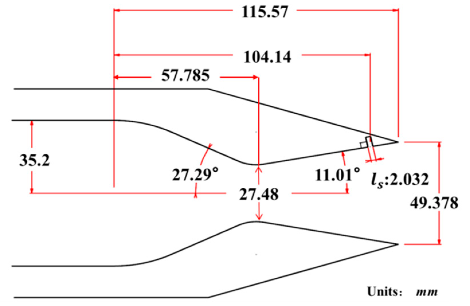
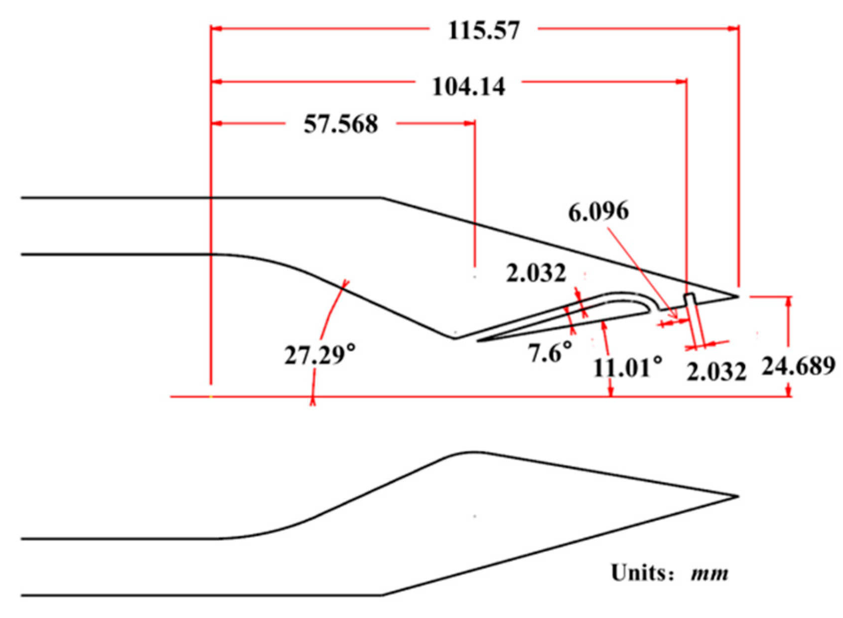
A two-dimensional SVC nozzle [19] designed by the NASA Langly Research Center (OSVC) is used as a validation example to confirm the solver’s accuracy. The nozzle length is 115.57 mm, the throat height is 27.48 mm, the distance from the nozzle inlet to the throat is 57.785 mm, the midpoint of the jet slot is 104.14 mm from the nozzle inlet, the jet slot width is 2.032 mm, and the nozzle inlet and outlet heights are 70.4 mm and 49.378 mm, respectively. The nozzle convergence and divergence angles are 27.29° and 11.01°, respectively. The secondary flow injection slot is perpendicular to the nozzle divergence section, and the specific geometry is shown in Figure 2. The design NPR is 8.78.
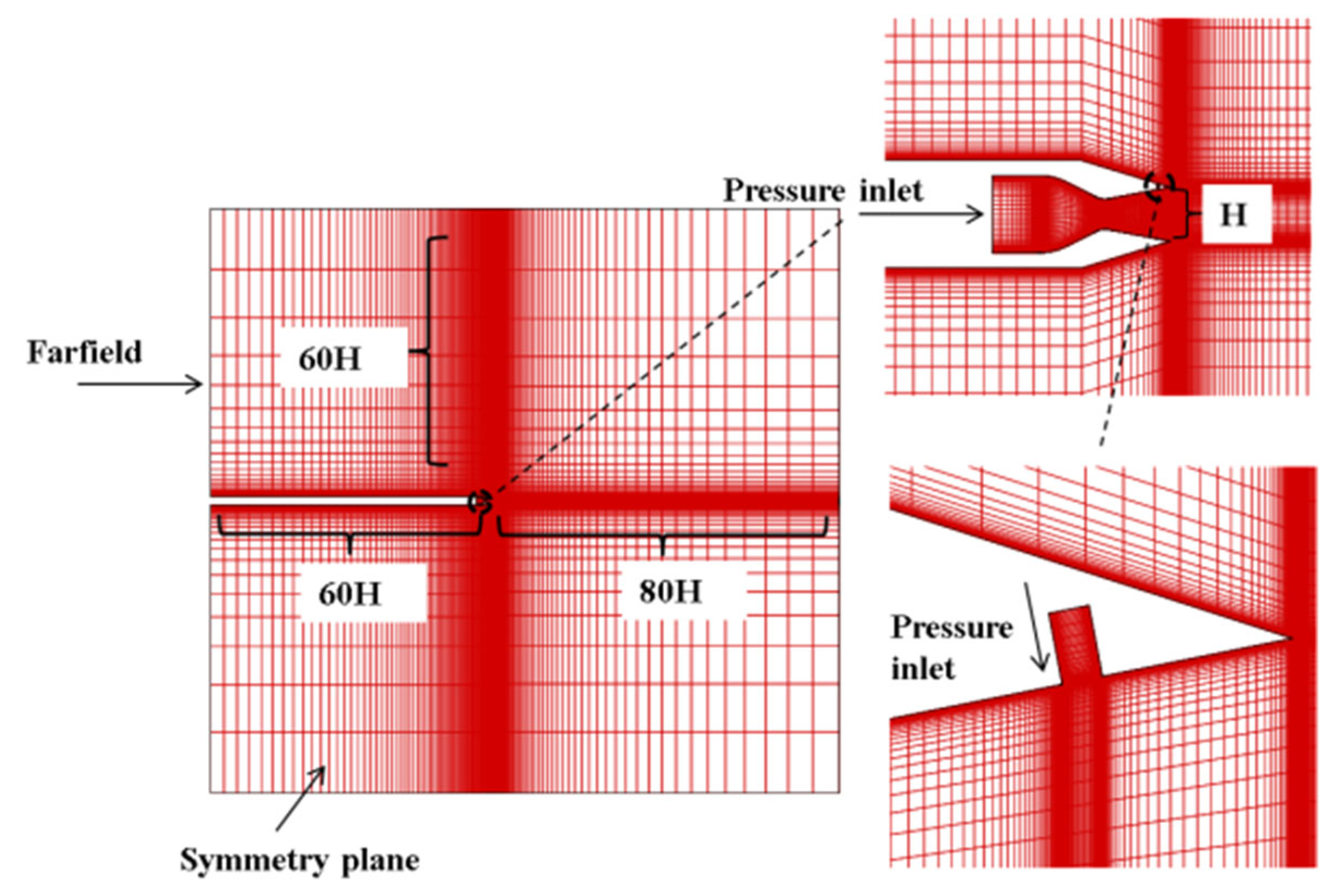
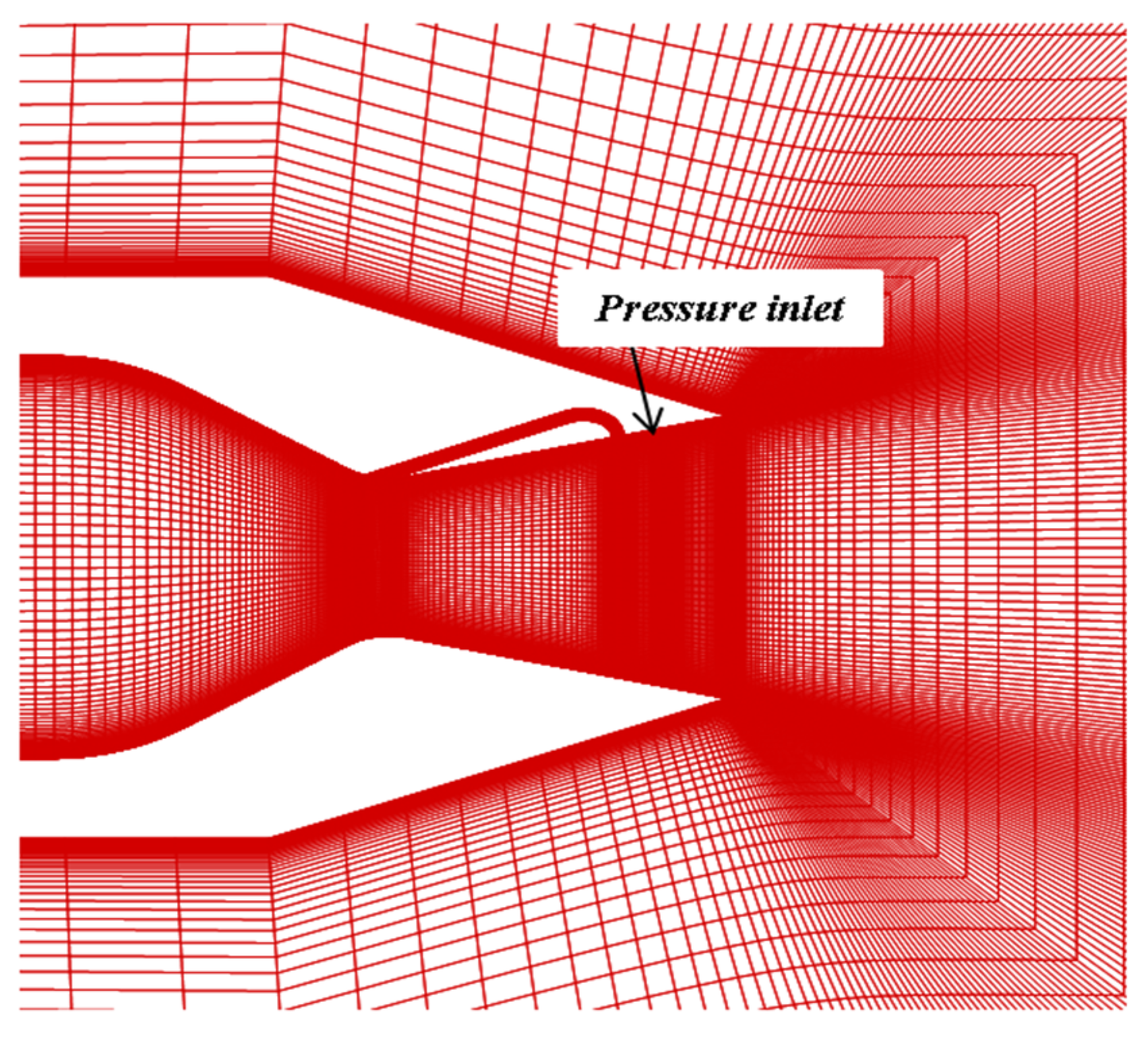
The grid and boundary conditions are shown in Figure 3. To ensure y + 1 , the first grid distance is 1 × 10 6 m. Starting from the midpoint of the nozzle outlet, 60 times and 80 times the nozzle throat height is extended upstream and downstream, respectively, and 60 times the outlet height is extended upward and downward as the boundary. The grid number is increased at the throat and secondary flow areas. The nozzle inlet and secondary inflow slots are given pressure inlet boundary conditions, Riemann invariant boundary conditions on all four sides, no-slip boundary conditions on the nozzle wall, and symmetric boundary conditions on the rest. To facilitate the solution of the three-dimensional Navier–Stokes equations, the grid is extended by one layer in the spanwise direction, with all extended areas assigned symmetric boundary conditions. For the pressure inlet conditions, the total temperatures for the primary and secondary flows are set at 300 K, with an ambient pressure of 101,325 Pa.

2.5. Grid Independence Analysis

The OSVC experiment was conducted in the Jet Exit Facility of the 16-foot transonic tunnel at the NASA Langley Research Center. During the test, the environmental condition was static on the ground, and the airflow within the nozzle was characterized by a cold state, with a total temperature of 300 K. The thrust coefficient and vector angle of the SVC nozzle under different NPRs and SPRs were obtained. In this section, the NPR = 4.6 and a secondary flow ratio of 4% are selected as the state of the experiment for verification.
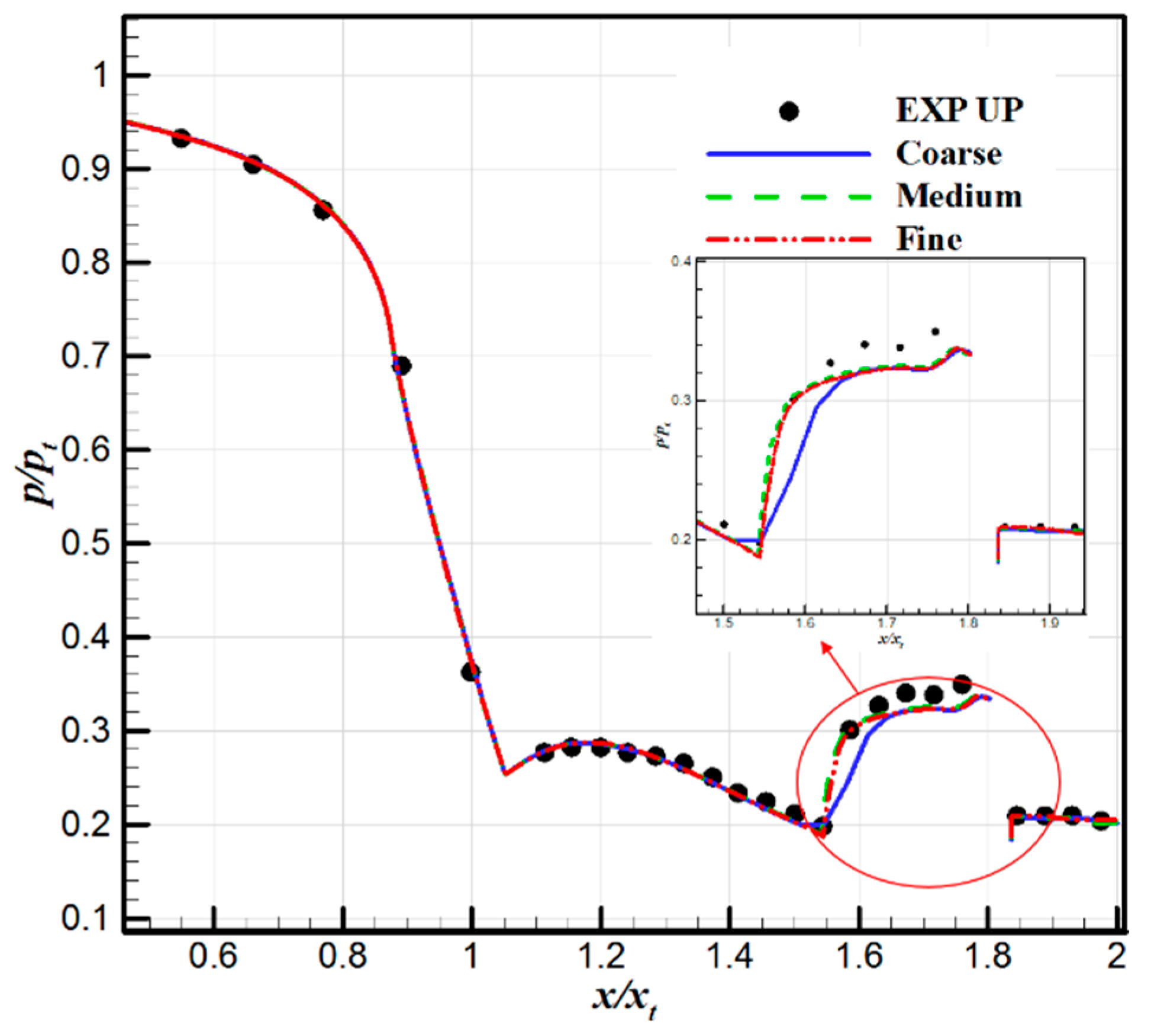
Three sets of coarse, medium, and fine grades are generated, corresponding to a grid of 70,000, 150,000, and 280,000. To align as closely as possible with the experimental conditions of the stationary incoming flow and to ensure computational convergence, the freestream Mach number is set at 0.05, the total temperatures for both primary and secondary flows are maintained at 300 K, and the NPR is fixed at 4.6. The SPR is adjusted to match the experimental secondary flow ratio of 4%, resulting in a calculated SPR of 0.55. The nozzle vector performance, as determined by different grid numbers, is presented in Table 1. It is important to note that the experimental results only provide the value of the vector angle but not the value of the thrust coefficient. Therefore, the thrust coefficient is compared with the elSA calculation results of ONERA [39,40]. With the increase in grid size, the thrust coefficient and vector angle calculated in this paper tend to be convergent. The thrust coefficient closely matched the elSA calculated results, while the vector angle was slightly larger than the experimental value.
The comparison between the calculated and experimental pressure distributions across different grid densities is presented in Figure 4. The dimensionless pressure distribution p / p t is dimensionless using the nozzle inlet total pressure p t , and the dimensionless cross coordinates x / x t are dimensionless using the nozzle throat cross coordinates x t . When the grid size is increased, the shock position obtained by the CFD is more consistent with the experimental data, the pressure rise behind the shock is steeper, and the predicted separation zone size is closer to the experimental data. In the prediction of peak pressure, the medium and fine grids are almost identical but still slightly lower than the experimental value. The RANS method is limited in its ability to capture the unsteady turbulent motion within the free shear layer, which results in an inaccurate prediction of Reynolds stress. This limitation also impacts the accuracy of the predictions regarding the size and intensity of the separation bubble [40].
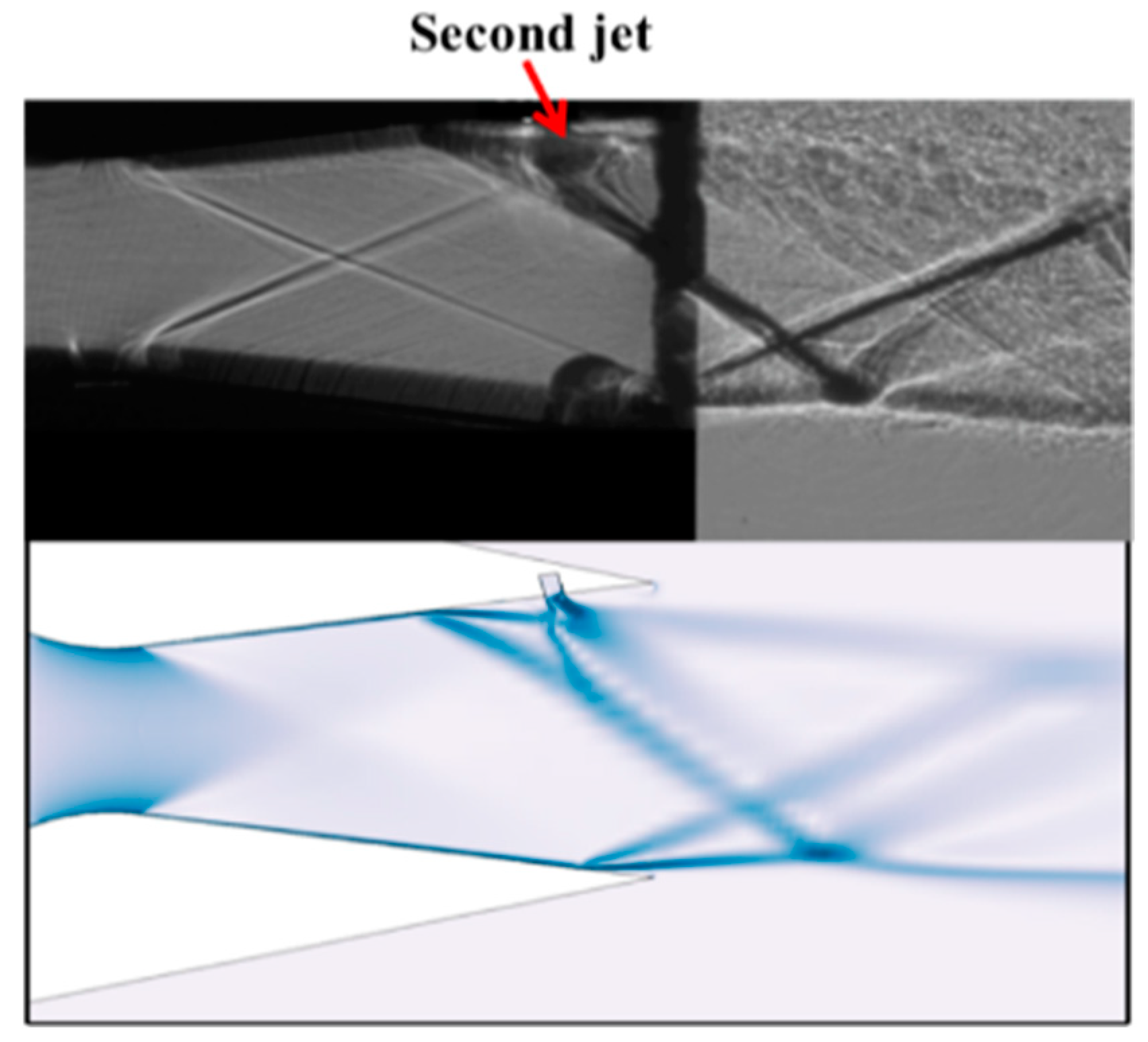
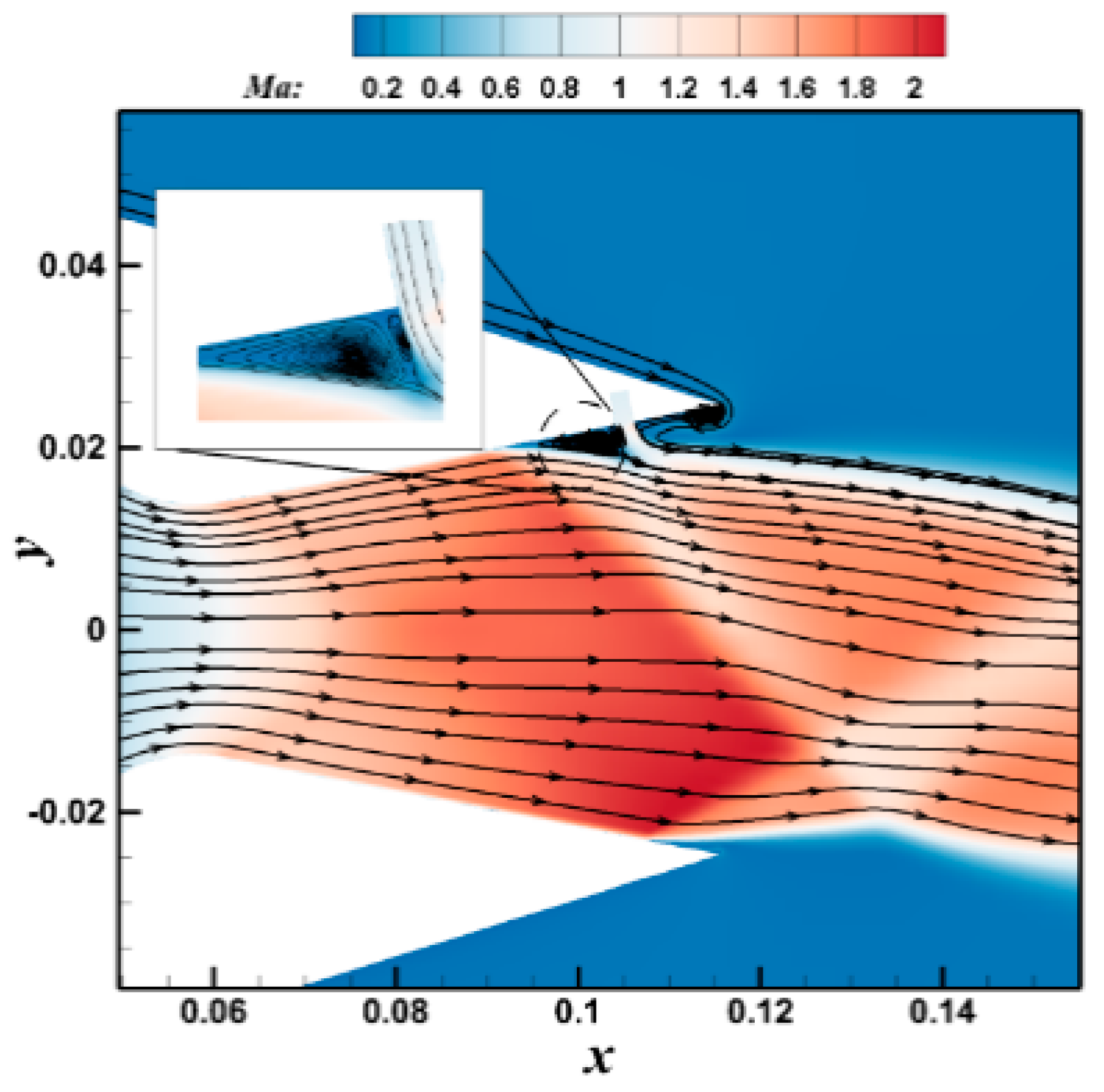
The schlieren comparison between the calculation and experiment is shown in Figure 5. When the NPR = 4.6 and the secondary flow ratio is 4%, the nozzle is over-expanded. When the jet is introduced into the upper surface of the nozzle, the flow becomes obstructed. Influenced by shock-boundary layer interference and jet entrainment effects, counter-rotating vortex pairs emerge in front of the jet. Both the separated shock wave and the jet-induced shock wave together form a λ shock-wave structure. It is evident that the results obtained from the medium grid calculations accurately depict the shock structure within the SVC nozzle. Figure 6 illustrates the calculated Mach number contours and streamlines in the nozzle, providing a more intuitive visualization of the counter-rotating vortex pairs in front of the jet. Given the considerations of computational cost, subsequent calculations are conducted using a medium grid.

3. Design of the ESVC

The FTV achieves thrust vectoring by relying on primary flow and secondary flow interferences, and currently, the secondary flow is mainly derived from the high-pressure secondary flow introduced by the engine. Increasing the secondary flow enhances the vector angle; however, this increment concurrently reduces engine performance. The ESVC has been developed based on the OSVC in conjunction with a bypass SVC nozzle and throat skewing. This design is depicted in Figure 7. The flow is injected in front of the OSVC secondary flow slot by drawing out part of the primary flow from the throat, and it works together with the OSVC secondary flow to form a multi-slot jet, which can be vector-controlled by using the primary flow drawn out from the throat alone or jointly with the OSVC secondary flow to increase the vector angle and vector efficiency without increasing the engine intake. Since the flow is diverted from the throat, the ESVC combines the effects of throat skewing and SVC control. The non-vectoring state can be achieved in practice by closing the valves of both flow paths.
The bypass channel in the ESVC maintains the same secondary flow channel width as the OSVC, both 2.032 mm, and is injected perpendicular to the convergence section of the nozzle. The ESVC parameters are the same as those of the OSVC except for the addition of a channel for air from the throat. The spacing between the two jets, a critical parameter affecting the vector performance of the ESVC, will be discussed in detail subsequently. For the ESVC baseline configuration, the spacing between the two jets is l = 6.096 mm, and the spacing is dimensionless with the OSVC jet slot width l s , then, l / l s = 3. The computational grid and boundary conditions are similar to those in Section 2.4, with the number of grids at the outlet of the bypass flow increased, and the number of grids is about 200,000. To simplify the calculation, the secondary flow jets of the OSVC are not drawn in the calculation, and the pressure inlet boundary condition is used instead, as shown in Figure 8.

4. Vector Performance of ESVC

In this section, the vector performance of the ESVC is investigated for different NPRs, SPRs, and different spacing between two jets and compared with the OSVC and bypassed nozzle (BSVC). Since the BSVC has no additional secondary flow and the theoretical SPR is always 1, the vectoring efficiency of the BSVC and the effect of the SPR on its vectoring performance are not compared. The total temperature of the primary flow of the nozzle is 800 K, and the total temperature of the secondary flow is 300 K for the calculation.

4.1. Effect of NPR

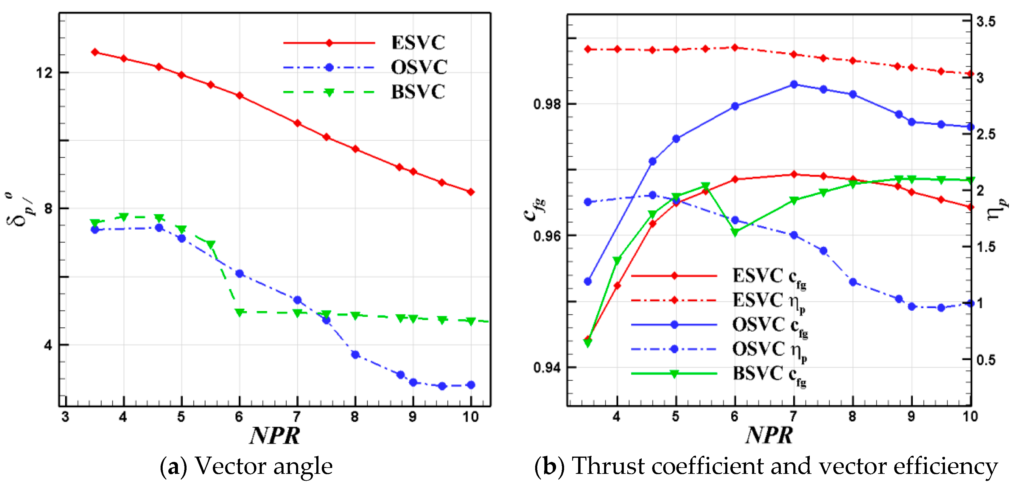
In order to obtain the performance of the nozzle in different expansion states, the NPR is taken to be 3.5–10, keeping the SPR at 0.55 and the dimensionless spacing between the two jets l / l s = 3. The vector angle, thrust coefficient, and vector efficiency with different NPRs are shown in Figure 9. The vector angle of the ESVC is substantially higher than the OSVC and BSVC, and the linearity of the vector angle change of the ESVC is significantly better than the OSVC and BSVC, so it has advantages in control.
The ESVC can still achieve a vector angle of more than 8° in the under-expansion state (operating the NPR is greater than the design NPR), while the OSVC has a vector angle of less than 4° and the BSVC less than 5° in the same state. The overall improvement in the vector angle of the ESVC over the OSVC and BSVC, by more than a factor of 2, significantly enhances the vector performance of the SVC nozzle in a given NPR range, especially in the under-expansion state. For the BSVC, its vector angle is slightly larger than the OSVC at an NPR of < 6, but a sudden change in vector angle occurs at NPR = 6, after which the vector angle is almost constant at about 5° as the NPR increases. Due to the presence of two jets in the divergence section, the shock loss of the ESVC nozzle is larger than that of the OSVC and BSVC, the thrust coefficient of the ESVC is smaller than that of the OSVC in a given NPR range, and its maximum thrust coefficient does not exceed 0.97, while the OSVC reaches 0.98. The thrust coefficient of the BSVC is almost identical to that of the ESVC at an NPR of <6, drops abruptly at NPR = 6, and then increases as the NPR increases. Compared with the OSVC, the thrust coefficient of the ESVC decreases by up to 1.4%. The vector efficiency of both the ESVC and OSVC decreases with an increasing NPR, and the vector efficiency of the ESVC is always greater than 3°/1% and changes smoothly with an increasing NPR, while the maximum of the OSVC does not exceed 2°/1%, and the vector efficiency of the OSVC decreases rapidly with an increasing NPR.
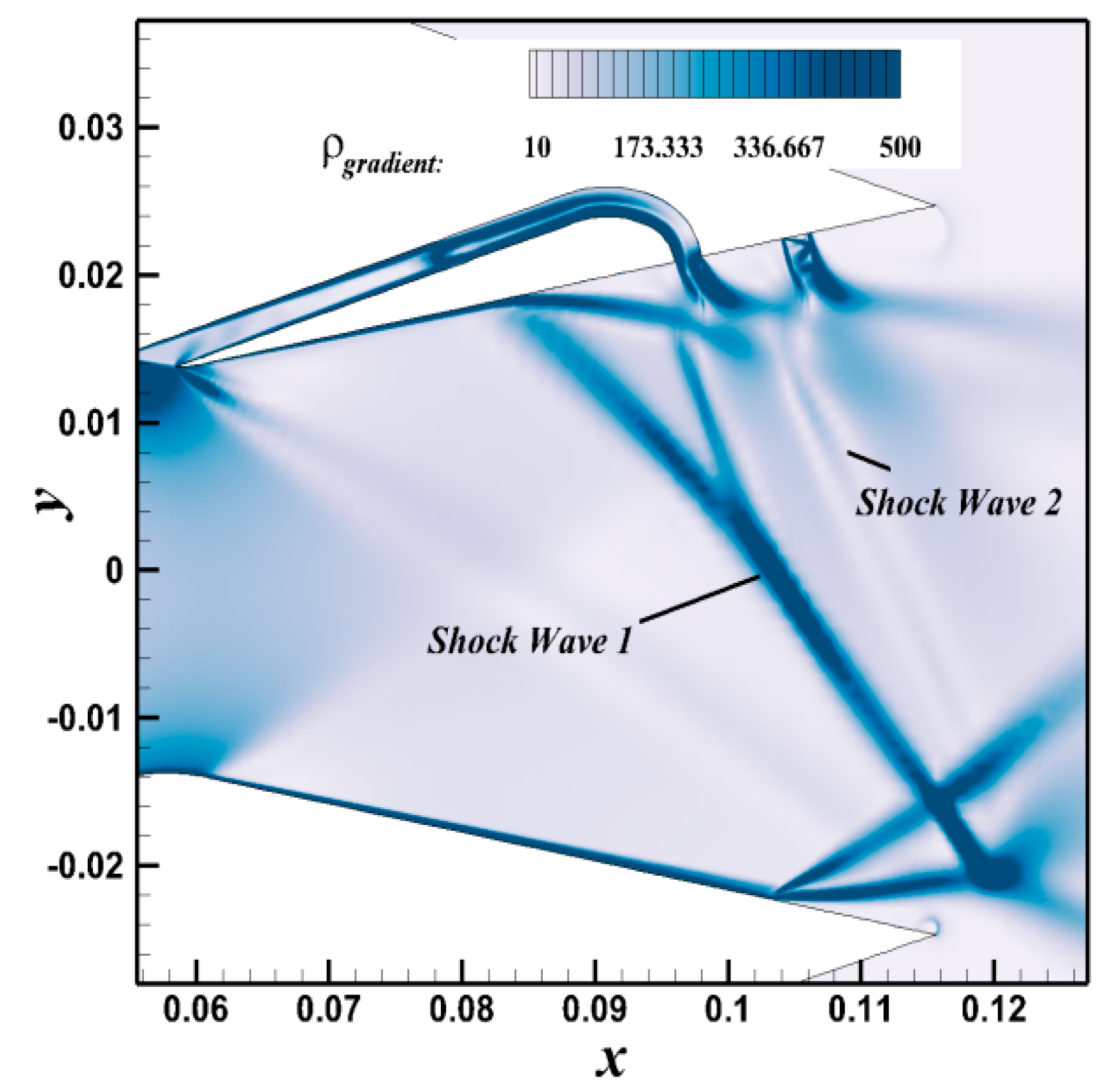
The density gradient contour of the ESVC at an NPR = 4.6 and the Ma contour are shown in Figure 10 and Figure 11. The intensity of the second shock, formed by the second jet and primary flow interference, is significantly weakened due to the slowing down of the flow velocity after the first shock. This is the biggest difference between the ESVC, OSVC, and BSVC. The OSVC and BSVC only have a pair of separating vortices before the jet, as shown in Figure 6. The penetration depth of the second jet is greater than that of the first jet, resulting in a higher separation bubble height in front of the second jet than in front of the first shock, while the size of the separation zone in front of the second shock is mainly limited by the spacing between the two jets.
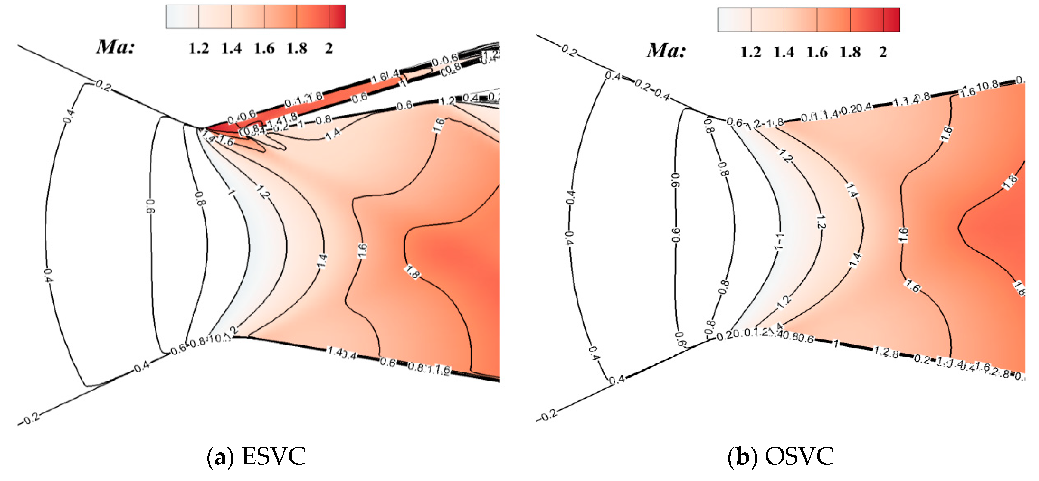
The upper surface pressure distributions of the three nozzles at NPR = 4.6, the comparison of the ESVC upper surface pressure distributions at different NPRs, and the Mach contours of the ESVC and OSVC are shown in Figure 12, Figure 13 and Figure 14. As seen in the figure, the main reason for the increase in the ESVC vector angle is the upper surface pressure plateau formed between the two jets, which leads to an increase in the pressure difference between the upper and lower surfaces of the nozzle. The pressure distribution on the upper and lower surfaces of the OSVC is the same before the shock is generated on the upper surface, indicating the same flow expansion state. In contrast, the ESVC and BSVC produce pressure differences between the upper and lower surfaces right at the throat, which continues until the nozzle exits. This indicates that the upper and lower surfaces of the nozzle are in different states of flow expansion due to the deflection of the sound velocity surface caused by the throat. The ESVC and BSVC have the characteristics of both the throat skewing nozzle and SVC nozzle, which is also demonstrated in Figure 14. Figure 12 shows that the ESVC vector angle decreases with an increasing NPR because the separation position before the first shock is far from the throat, the separation zone is reduced, and the pressure plateau in the separation zone between the two jets and the exit decreases significantly, resulting in a decrease in the pressure difference between the upper and lower surfaces of the nozzle.
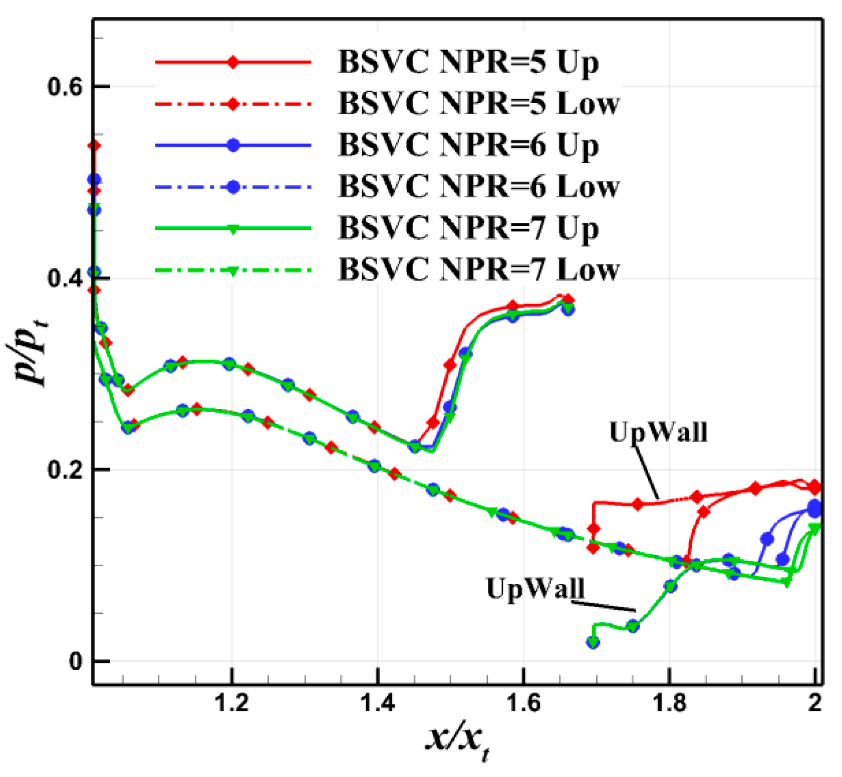
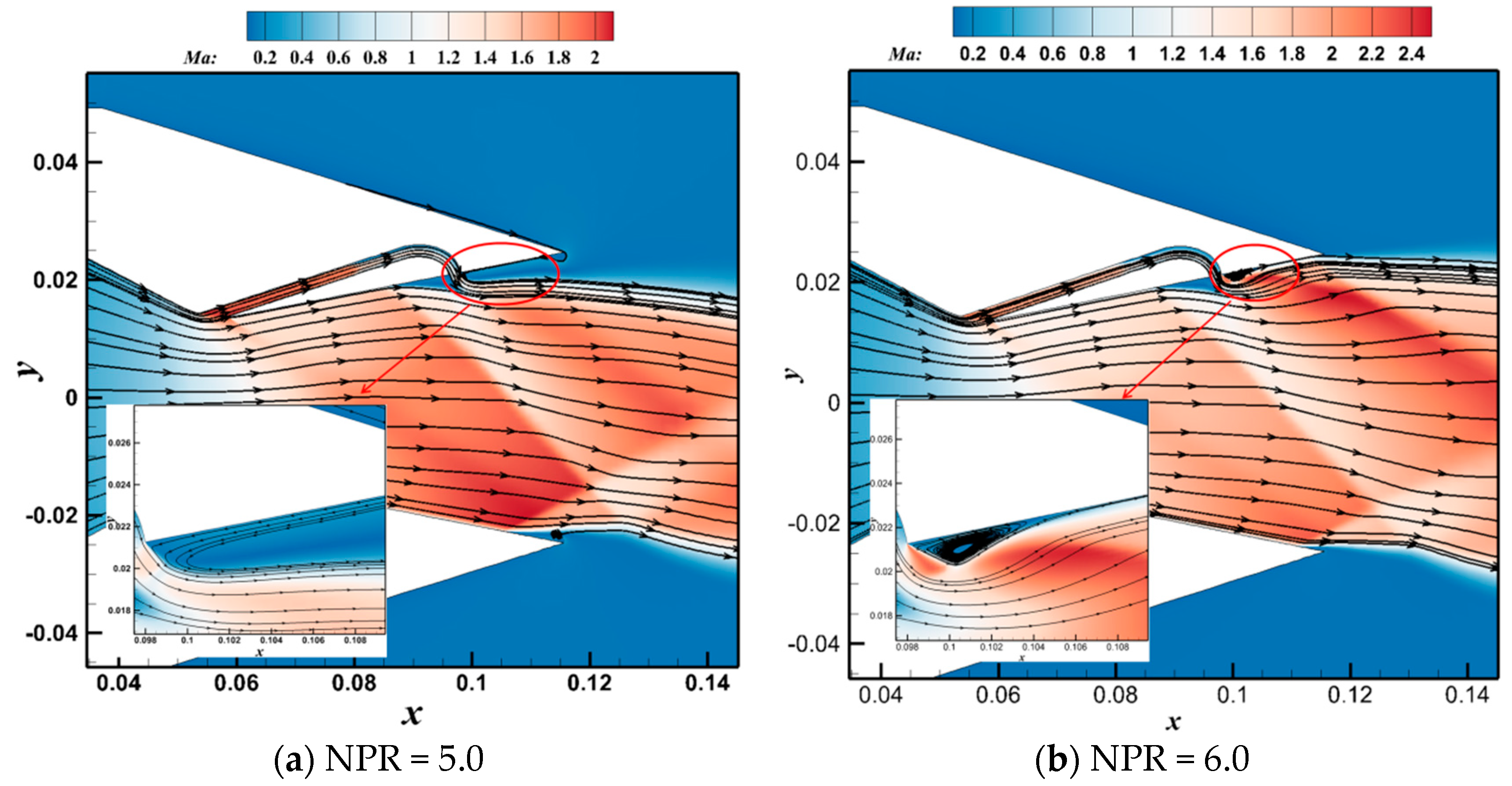
The reason for the abrupt change in the vector angle and thrust coefficient of the BSVC for an NPR = 6 can be explained in Figure 15 and Figure 16. With an increasing NPR, the shock position on the upper surface of the BSVC changes very little after NPR = 6. The pressure distribution on the lower surface shows that as the NPR increases, the shock position gradually moves closer to the nozzle exit due to reduced over-expansion. The sudden change in the BSVC vector angle and thrust coefficient at the NPR = 6 is due to the change in the morphology of the reattachment zone following the jet. At the NPR = 6, reattachment occurs downstream of the jet, causing an abrupt drop in the upper surface pressure. After a brief plateau, the pressure begins to recover, although it remains lower than that on the lower surface of the nozzle. The NPR is then increased, and the entire upper surface pressure distribution does not change in nature. The resulting sudden drop in the pressure difference between the upper and lower surfaces of the nozzle leads to an abrupt change in the vector angle. Upon further increasing the NPR, the aerodynamic surface remains fixed, and the increase in the thrust coefficient results from the gradual transition from over-expansion to full expansion, with a slight decrease in the thrust coefficient following the under-expansion state. Figure 16 provides the Ma contour and streamline comparison of the nozzle at NPR = 5 and NPR = 6. It is evident that reattachment occurs in the return area downstream of the BSVC jet at the NPR = 6. This alters the overall shape of the nozzle, significantly changing the expansion state compared to scenarios without reattachment.

4.2. Effect of SPR

To ensure that the secondary flow sufficiently influences the primary flow, the NPR is fixed at 4.6. This study investigates and compares the vector performance of the ESVC and OSVC as the SPR ranges from 0.55 to 2.0.
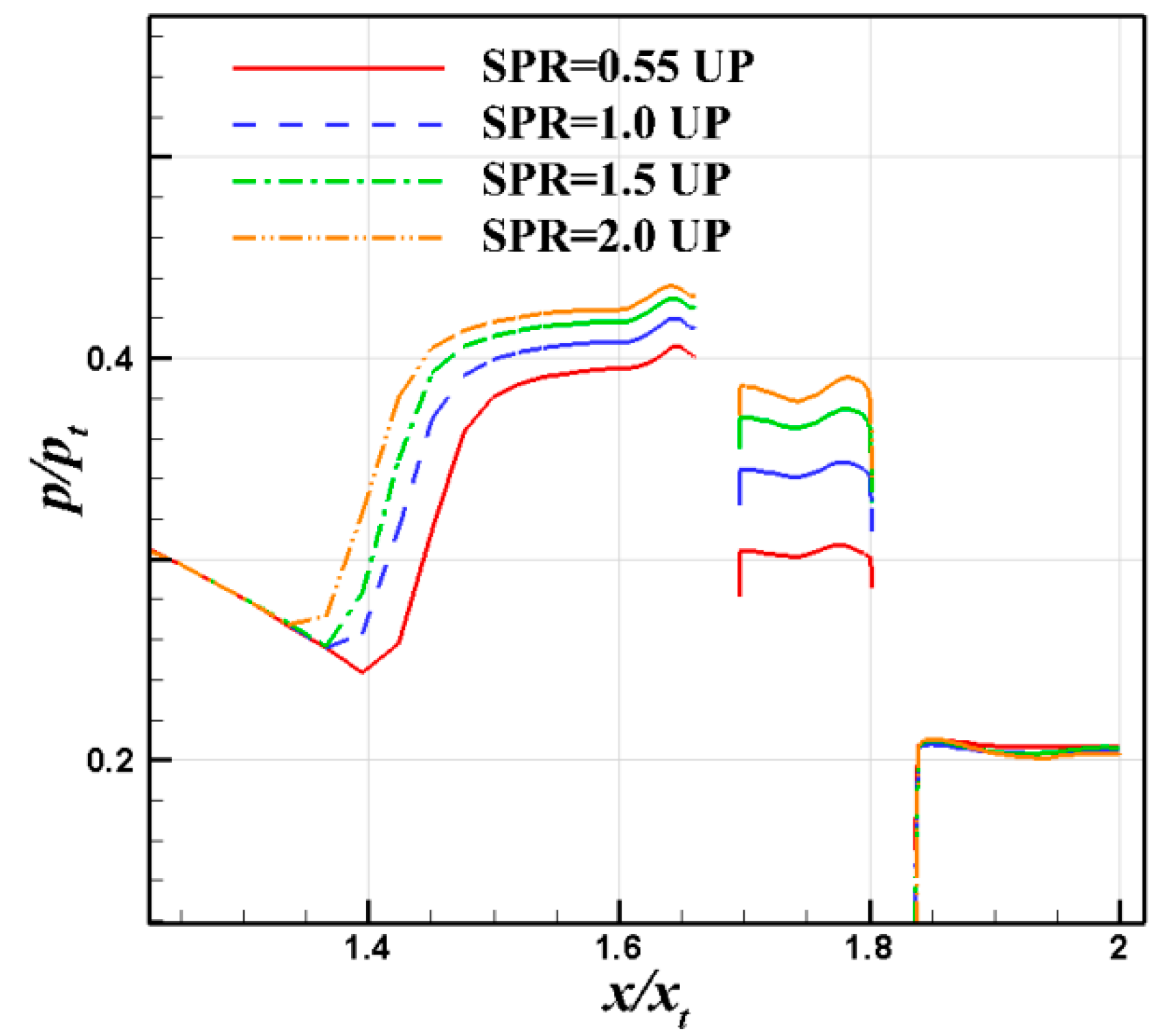
Figure 17 displays the vector performance comparison for both nozzles, showing consistent trends: as the SPR increases, the vector angle rises, while the thrust coefficient and vector efficiency generally decrease. In fact, increasing the SPR affects only the second jet. The impact of raising the SPR on the vector angle and efficiency of the ESVC is primarily in the separation zone between the two jets. An increase in the SPR results in a stronger blocking effect of the secondary flow on the primary flow, leading to a greater shock loss and, consequently, a decrease in the thrust coefficient. This reduction in vector efficiency suggests that the increase in vector angle is less significant than the increase in secondary flow. The vector angle for the ESVC always exceeds 12° and reaches a maximum of 17°. In contrast, the vector angle for the OSVC does not surpass 14° for the specified range of the SPR, and the vector angle for the ESVC increases by more than 5° compared to the OSVC. Although the thrust coefficient for the ESVC is consistently lower than that for the OSVC, it still remains above 0.95 within the study’s defined range.
The pressure distribution on the upper surface of the ESVC at different SPRs is depicted in Figure 18. As the SPR increases, the shock before the first jet progressively moves toward the throat, resulting in a longer separation length and a broader pressure range across the platform. The most significant changes occur at the pressure platform before the second jet. Although the range remains the same, the pressure platform noticeably elevates with an increase in the SPR. This elevation is primarily due to the enhanced momentum of the second jet, which increases the penetration depth and intensifies the blocking and entrainment effects on the primary flow. Consequently, the vector angle of the ESVC increases due to these combined effects.
The Mach contour of the ESVC at different SPRs is illustrated in Figure 19. It is evident that the separation zone before the first jet expands as the SPR increases, the penetration depth of the second jet is greater, and the separation zone between the two jets becomes deeper. It is important to note that due to the potential inaccuracies of the RANS method and the inherent limitations of the eddy-viscosity model, more precise methodologies such as detached eddy simulation (DES), large eddy simulation (LES), and experimental approaches should be employed to accurately quantify the details of the reaction separation bubbles.

4.3. Effect of Spacing between Two Jets

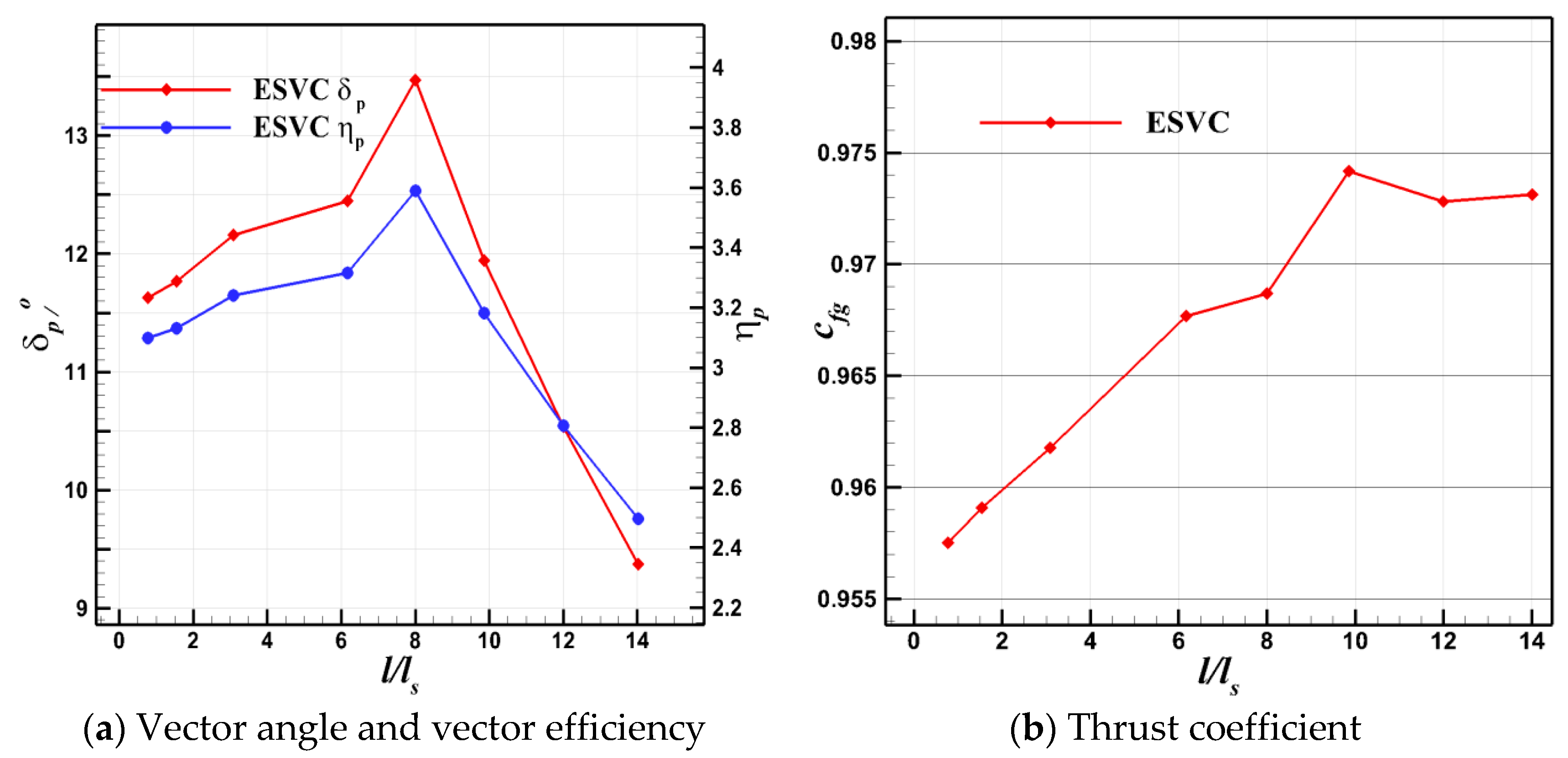
The spacing between the two jets significantly influences the separation strength and range, which are crucial parameters affecting the vector performance of the ESVC. By setting the NPR to 4.6 and the SPR to 0.55, the effect of jet spacing on the ESVC vector performance is examined. Keeping the position of the second jet constant while varying the position of the first jet, the vector performance of the ESVC nozzle is compared across eight different spacings, corresponding to l / l s = 0.8, 1.5, 3.0, 6.2, 8.0, 10.0, 12.0, and 14.0, respectively. The original case corresponds to l / l s = 3.0. The vector performance curve of the ESVC with varying spacing is presented in Figure 20. Both the vector angle and vector efficiency initially increase with spacing and then decrease, peaking at l / l s = 8, with a vector angle of 13.47° and vector efficiency of 3.59°/1% of the jet. This represents an increase of 1.32° and 0.35°/1 of the jet compared to the original case of l / l s = 3. The thrust coefficient reaches its maximum of 0.974 at l / l s = 10, which is an increase of 0.013 from the original case, and then stabilizes.
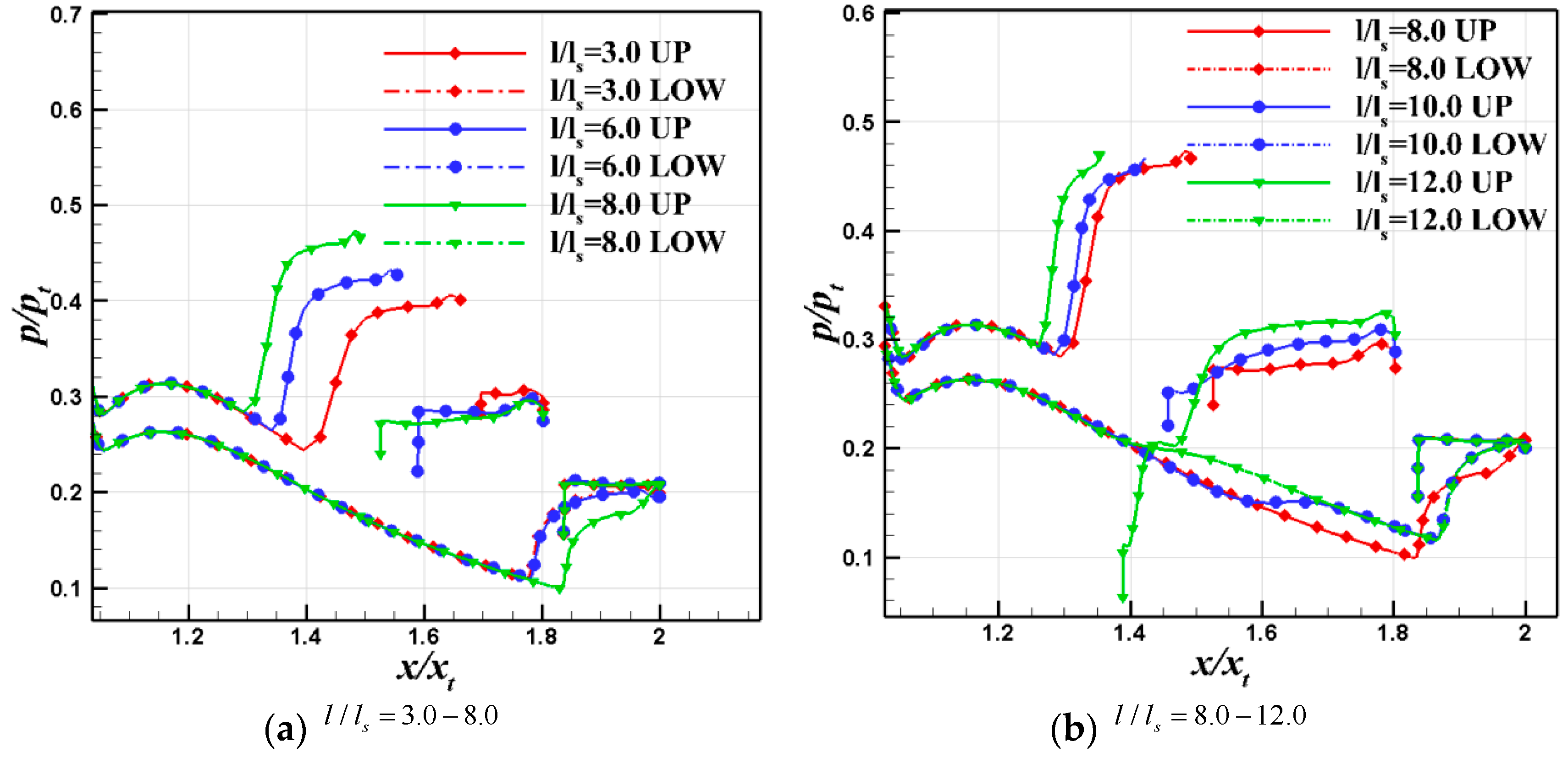
A comparison of the pressure distribution on the nozzle surface at different spacings is shown in Figure 21. For l / l s 8 , the separation (pressure plateau) occurs on the upper surface after the first jet, and the separation range increases as the spacing increases. After l / l s > 8 , the separation zone before the first jet is significantly reduced, and the flow after the first jet accelerates before the pressure plateau appears. The pressure decreases after the jet, and this decrease becomes more pronounced with increasing distance. At l / l s > 8 , the lower surface exhibits a pressure rise in front of the shock, and the location of this pressure rise progressively moves forward as the spacing increases. This occurs because as the first jet moves forward, the generated shock also moves forward, impacting the lower surface and causing the adverse pressure gradient to propagate upstream from the boundary layer, leading to the pressure rise. When considering the changes in nozzle pressure distribution, at l / l s 8 , the lower surface near the nozzle exit experiences a pressure rise, the range of the high-pressure area on the upper surface increases, and the pressure difference between the upper and lower surfaces enlarges, enhancing the vector angle and vector efficiency. Conversely, at l / l s > 8 , the pressure on the upper surface after the first jet decreases while a pressure rise appears on the lower surface, reducing the overall pressure difference and leading to a decrease in both the vector angle and vector efficiency. At l / l s = 12 , separation occurs after the first jet reattachment. It is observed that the pressure distribution on the upper surface rapidly surpasses that of the lower surface and continues to accelerate after a very short pressure plateau, eventually forming a longer pressure plateau.
The contour of the nozzle density gradient and streamlines at different spacings is displayed in Figure 22. As the jet spacing increases, the separation zone between the two jets significantly expands, and the intensity of the shock before the second jet increases, with the type of shock structure gradually becoming evident. The mutual interference between the two jets diminishes, and the intensity of the shock before the first jet gradually weakens. Two factors influence the flow structure in front of the first jet: first, as the spacing increases (moving the first jet forward), the Mach number of the primary flow in front of the exit of the induced gas jet decreases; second, as the spacing increases, the static pressure at the exit of the first rises, the ratio of the total inlet pressure to the static pressure at the exit decreases, and the actual flow rate of the first jet diminishes. It can be seen that at l / l s > 8 , the actual flow rate is regulated by the separation in the bypass tube. As the spacing increases, the separation area at the throat channel enlarges, and the actual flow rate of the first jet progressively decreases. Under the combined influence of both factors, the shock before the first jet weakens, and the separation zone is reduced. At the point where l / l s = 12 , the separation zone after the first jet is reattached by the primary flow, which corresponds to the low-pressure zone after the first jet in Figure 20. This process undergoes a sudden pressure rise, continuing to rise after a brief pressure plateau, forming a larger pressure plateau. The reattachment separation alters the aerodynamic profile of the nozzle, significantly changes the expansion state, and reduces the thrust coefficient. With further increases in spacing, the flow from the first jet is very small, the interference from the primary flow is further diminished, the thrust coefficient changes very little, and both the vector angle and vector efficiency decrease significantly. As noted in Section 4.3, the analysis of the separation area in this section is mainly qualitative, while quantitative analysis would require more precise computational methods or experiments.
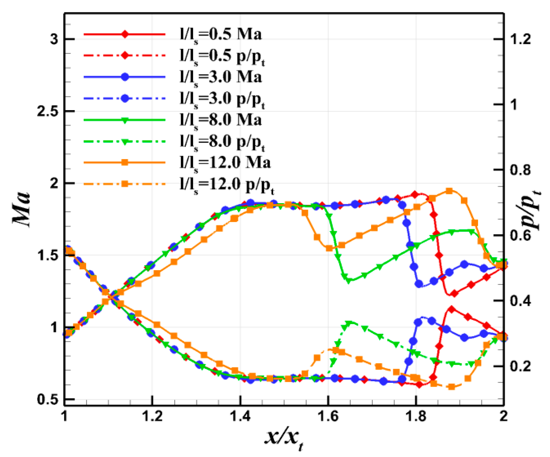
The centerline Mach number and dimensionless pressure distribution of the ESVC nozzle at various spacings are depicted in Figure 23. It is observed that at minimal spacings, only the shock preceding the first jet is present in the flow field. Following this shock, the flow briefly continues to expand, with the Mach number of the primary flow before the second jet remaining low, insufficient to interact with the second jet and induce a shock. As the spacing increases, the primary flow subsequent to the first shock expands to a higher Mach number, sufficient to interact with the second jet and generate a second shock, although the intensity of both shocks is reduced compared to the scenario with a singular shock. Further increasing the distance, at l / l s = 12 , separation occurs in the bypass tube due to the reattachment after the first jet and a reduction in the passable flow within the tube. Consequently, both the nozzle profile and the shock structure alter, leading to a pronounced λ shock structure in front of the second jet and resulting in a distinct centerline Mach number and dimensionless pressure distribution compared to other cases. In instances of separation without reattachment following the first jet, as the spacing increases, the vector angle and vector efficiency, achieved by the primary flow going through two weaker shocks, exceed those from traversing a single strong shock.

5. Conclusions

To address the conflict between enhancing nozzle vector performance and preserving engine efficiency, a throat bypass shock vectoring nozzle is proposed. This nozzle can be operated independently or in conjunction with the original SVC nozzle. Its vector performance has been analyzed using CFD, yielding the following conclusions.
(1)
The ESVC integrates features from both throat skewing and SVC nozzles, capitalizing on the priming effect of the original secondary flow. This integration effectively eliminates the separation and reattachment phenomena observed in the BSVC after injection at specific pressure ratios. Consequently, the vectoring performances of both the BSVC and OSVC are significantly enhanced without necessitating an increase in the induced airflow from the engine.
(2)
The linearity of the vector angle variation with the NPR in the ESVC surpasses that of both the OSVC and BSVC, facilitating easier control. The vector angle and vector efficiency of the ESVC are more than twice as favorable as those of the OSVC, significantly enhancing the performance of the SVC nozzle under under-expansion conditions. Furthermore, within a specified SPR range, the vector angle and vector efficiency of the ESVC are substantially improved compared to the OSVC, achieving a vector angle exceeding 18° and a thrust coefficient surpassing 0.95.
(3)
The distance between two jets is a critical parameter influencing the vector performance of the ESVC. The vector performance of the ESVC initially increases and then decreases with the widening spacing between the two jets, indicating the existence of optimal jet spacing. To ensure that the separation between the two jets does not reattach, it is observed that the vector performance achieved by the flow traversing through two weaker shocks is superior to that resulting from passing through a single strong excitation. Consequently, the design should strategically avoid the reattachment of separation following the jet.
The present study evaluates the aerodynamic performance of ESVC nozzles and identifies significant performance enhancements of the ESVC relative to the OSVC. However, the scope of the current research is confined to the macroscopic mechanical characteristics of the nozzle in a cold flow state, primarily emphasizing a qualitative analysis of flow phenomena such as separation. Future work will involve a detailed simulation of the nozzle flow field by the DES or LES methods and wind tunnel testing to conduct a sensitivity analysis of the key parameters and to assess nozzle performance under gaseous conditions.

Author Contributions

Conceptualization, B.S. and Z.G.; methodology and software, B.S. and C.H.; Validation, B.S and C.H.; formal analysis, B.S and H.Z.; investigation, H.Z.; resources, Z.G. and J.H.; data curation, L.X. and H.Z. All authors have read and agreed to the published version of the manuscript.

Funding

This work was supported by National Natural Science Foundation of China (Grant No. 12102489).

Data Availability Statement

Data can be provided with the consent of the corresponding author.

Conflicts of Interest

The authors declare no conflict of interest.

References

  1. Francis, M.S. Air vehicle management with integrated thrust-vector control. AIAA J. 2018, 56, 4741–4751. [Google Scholar] [CrossRef]
  2. Kowal, H.J. Advances in thrust vectoring and the application of flow-control technology. Can. Aeronaut. Space J. 2002, 48, 145–151. [Google Scholar] [CrossRef]
  3. Xiao, Z.Y.; Jiang, X.; Mou, B.; Chen, Z. Advances in fluidic thrust vectoring technique research. J. Exp. Fluid Mech. 2017, 31, 8–15. [Google Scholar]
  4. Walker, S. Lessons learned in the development of a national cooperative program. In Proceedings of the 33rd Joint Propulsion Conference and Exhibit, Seattle, WA, USA, 6–9 July 1997; p. 3348. [Google Scholar]
  5. Clyde, W.; William, J.C. Fludic flow effectors for flight control. AIAA J. 2018, 56, 3808–3823. [Google Scholar]
  6. Deere, K.A. Summary of fluidic thrust vectoring research conducted at NASA Langley research center. In Proceedings of the 21st AIAA Applied Aerodynamics Conference, Orlando, FL, USA, 23–26 June 2003; p. 3800. [Google Scholar]
  7. Wen, X.; Zhou, K.W.; Liu, P.; Zhu, H.; Wang, Q.; Liu, Y. Schlieren Visualization of Coflow Fluidic Thrust Vectoring Using Sweeping Jets. AIAA J. 2022, 60, 435–444. [Google Scholar] [CrossRef]
  8. Mason, M.S.; Crowther, W.J. Fluidic thrust vectoring for low observable air vehicles. In Proceedings of the 2nd AIAA Flow Control Conference, Portland, OR, USA, 28 June–1 July 2004; p. 2210. [Google Scholar]
  9. Wang, Y.S.; Xu, J.L.; Huang, S. Study of starting problem of axisymmetric divergent dual throat nozzle. J. Eng. Gas Turbines Power 2017, 139, 062602. [Google Scholar] [CrossRef]
  10. Yagle, P.J.; Miller, D.N.; Ginn, K.B.; Hamstra, J.W. Demonstration of fluidic throat skewing for thrust vectoring in structurally fixed nozzles. J. Eng. Gas Turbines Power 2001, 123, 502–507. [Google Scholar] [CrossRef]
  11. Flamm, J.; Deere, K.; Mason, M.; Berrier, B.; Johnson, S. Experimental study of an axisymmetric dual throat flu-idic thrust vectoring nozzle for supersonic aircraft application. In Proceedings of the 43rd AI-AA/ASME/SAE/ASEE Joint Propulsion Conference & Exhibit, Cincinnati, OH, USA, 8–11 July 2007; p. 5084. [Google Scholar]
  12. Ferlauto, M.; Marsilio, R. Numerical investigation of the dynamic characteristics of a du-al-throat-nozzle for fluidic thrust-vectoring. AIAA J. 2017, 55, 86–98. [Google Scholar] [CrossRef]
  13. Wang, Y.; Xu, J.; Huang, S.; Jiang, J.; Pan, R. Design and preliminary analysis of the variable axisym-metric divergent bypass dual throat nozzle. J. Fluids Eng. 2020, 142, 061204. [Google Scholar] [CrossRef]
  14. Wu, K.; Kim, H.D.; Jin, Y.Z. Fluidic thrust vector control based on counter-flow concept. Proc. Inst. Mech. Eng. Part G J. Aerosp. Eng. 2019, 233, 1412–1422. [Google Scholar] [CrossRef]
  15. Jegede, O. Dual-Axis Fluidic Thrust Vectoring of High Aspect Ratio Supersonic Jets. Ph.D. Thesis, Manchester University, Manchester, UK, 2016. [Google Scholar]
  16. Shi, N.X.; Gu, Y.S.; Zhou, Y.H.; Wang, L.X.; Feng, C.; Li, L.K. Mechanism of hysteresis and uncontrolled deflection in jet vectoring control based on Coanda effect. Phys. Fluids 2022, 34, 084107. [Google Scholar] [CrossRef]
  17. Shi, J.W. Investigation on Flow Mechanism and Performance Estimation of Fixed-Geometric Thrust Vectoring Nozzle. Ph.D. Thesis, Northwestern Polytechnical University, Xi’an, China, 2015. [Google Scholar]
  18. Emelyanov, V.N.; Teterina, I.V.; Volkov, K.N.; Garkushev, A.U. Pressure oscillations and instability of working processes in the combustion chambers of solid rocket motors. Acta Astronaut. 2017, 135, 183–195. [Google Scholar] [CrossRef]
  19. Waithe, K.; Deere, K. An experimental and computational investigation of multiple injection ports in a convergent-divergent nozzle for fluidic thrust vectoring. In Proceedings of the 21st AIAA Applied Aerodynamics Conference, Orlando, FL, USA, 23–26 June 2003; p. 3802. [Google Scholar]
  20. Viti, V.; Neel, R.; Schetz, J.A. Detailed flow physics of the supersonic jet interaction flow field. Phys. Fluids 2009, 21, 046101. [Google Scholar] [CrossRef]
  21. Zmijanovic, V.; Lago, V.; Sellam, M.; Chpoun, A. Thrust shock vector control of an axisymmetric conical supersonic nozzle via secondary transverse gas injection. Shock Waves 2014, 24, 97–111. [Google Scholar] [CrossRef]
  22. Zmijanovic, V.; Leger, L.; Depussay, E. Experimental-numerical Parametric investigation of a rocket nozzle secondary injection thrust vectoring. J. Propuls. Power 2016, 32, 196–213. [Google Scholar] [CrossRef]
  23. Forghany, F.; Taeibe-Rahni, M.; Asadollahi-Ghohieh, A.; Banazdeh, A. Numerical investigation of in-jection angle effects on shock vector control performance. Proc. Inst. Mech. Eng. Part G J. Aerosp. Eng. 2019, 233, 405–417. [Google Scholar] [CrossRef]
  24. Chen, J.L.; Liao, Y.H. Parametric study on thrust vectoring with a secondary injection in a convergent–divergent nozzle. J. Aerosp. Eng. 2020, 33, 04020020. [Google Scholar] [CrossRef]
  25. Emelyanov, V.; Yakovchuk, M.; Volkov, K. Multiparameter optimization of thrust vector con-trol with transverse injection of a supersonic underexpanded gas jet into a convergent diver-gent nozzle. Energies 2021, 14, 4359. [Google Scholar] [CrossRef]
  26. Younes, K.; Hickey, J.P. Fludic thrust shock-vectoring control: A sensitivity analysis. AIAA J. 2020, 58, 1887–1890. [Google Scholar] [CrossRef]
  27. Shu, B.W.; Huang, J.T.; Gao, Z.H.; Liu, G.; He, C.; Xia, L. Sensitivity analysis of vector performance of two-dimensional shock vector control nozzle. Acta Aeronaut. Astronaut. Sin. 2023, 44, 127831. [Google Scholar]
  28. Gu, R.; Xu, J.; Guo, S. Experimental and numerical investigations of a bypass dual throat nozzle. J. Eng. Gas Turbines Power 2014, 136, 084501. [Google Scholar] [CrossRef]
  29. Huang, S.; Xu, J.; Yu, K.; Wang, Y.; Pan, R. Design and experimental study of a bypass dual throat nozzle with the ability of short/vertical takeoff and landing. Aerosp. Sci. Technol. 2022, 121, 107301. [Google Scholar] [CrossRef]
  30. Huang, S.; Xu, J.L.; Yu, K.K.; Wang, Y.; Pan, R.; Chen, K.; Zhang, Y. Numerical study of a trapezoidal bypass dual throat nozzle. Chin. J. Aeronaut. 2023, 36, 42–62. [Google Scholar] [CrossRef]
  31. Deng, R.; Kim, H.D. A study on the thrust vector control using a bypass flow passage. Proc. Inst. Mech. Eng. Part G J. Aerosp. Eng. 2015, 229, 1722–1729. [Google Scholar] [CrossRef]
  32. Deng, R.; Setoguchi, T.; Kim, H.D. Large eddy simulation of shock vector control using bypass flow passage. Int. J. Heat Fluid Flow 2016, 62, 474–481. [Google Scholar] [CrossRef]
  33. Shi, J.W.; Wang, Z.X.; Zhou, L. Numerical investigation on a new concept of shock vector control nozzle. J. Eng. Gas Turbines Power 2019, 141, 091004. [Google Scholar]
  34. Ferlauto, M.; Marsilio, R. On the use of synthetic jet actuators to induce jet-vectoring in nozzles. In Proceedings of the 2018 AIAA Aerospace Sciences Meeting, Kissimmee, FL, USA, 8–12 January 2018; p. 1627. [Google Scholar]
  35. Huang, J.T.; Zhou, Z.; Yu, J.; Gao, Z.H.; Yu, L. Sensitivity analysis of design variables considering intake and exhaust effects. J. Propuls. Technol. 2019, 40, 250–258. [Google Scholar]
  36. Zhou, Z.; Yu, Y.G.; Liu, G.; Chen, Z.B.; Heng, K.F. Comprehensive study on yaw control characteristic of com-bined control surfaces of flying wing configuration. Acta Aeronaut. Astronaut. Sin. 2020, 41, 523422. [Google Scholar]
  37. Liu, G.; Xiao, Z.Y.; Wang, J.T.; Liu, F. Numerical simulation of missile air-launching process under rail slideway constraints. Acta Aerodyn. Sin. 2015, 33, 192–197. [Google Scholar]
  38. Menter, F.R. Two-equation eddy-viscosity turbulence models for engineering applications. AIAA J. 1994, 32, 1598–1605. [Google Scholar] [CrossRef]
  39. Mangin, B.; Chopun, A.; Jacquin, L. Experimental and numerical study of the fluidic thrust vectoring of a two-dimensional supersonic nozzle. In Proceedings of the 24th Applied Aerodynamics Conference, San Francisco, CA, USA, 5–8 June 2006; p. 3666. [Google Scholar]
  40. Jakirlic, S.; Maduta, R. Extending the bounds of steady rans closures: Toward an instability sensitive Reynolds stress model. Int. J. Heat Fluid Flow 2015, 51, 175–194. [Google Scholar] [CrossRef]
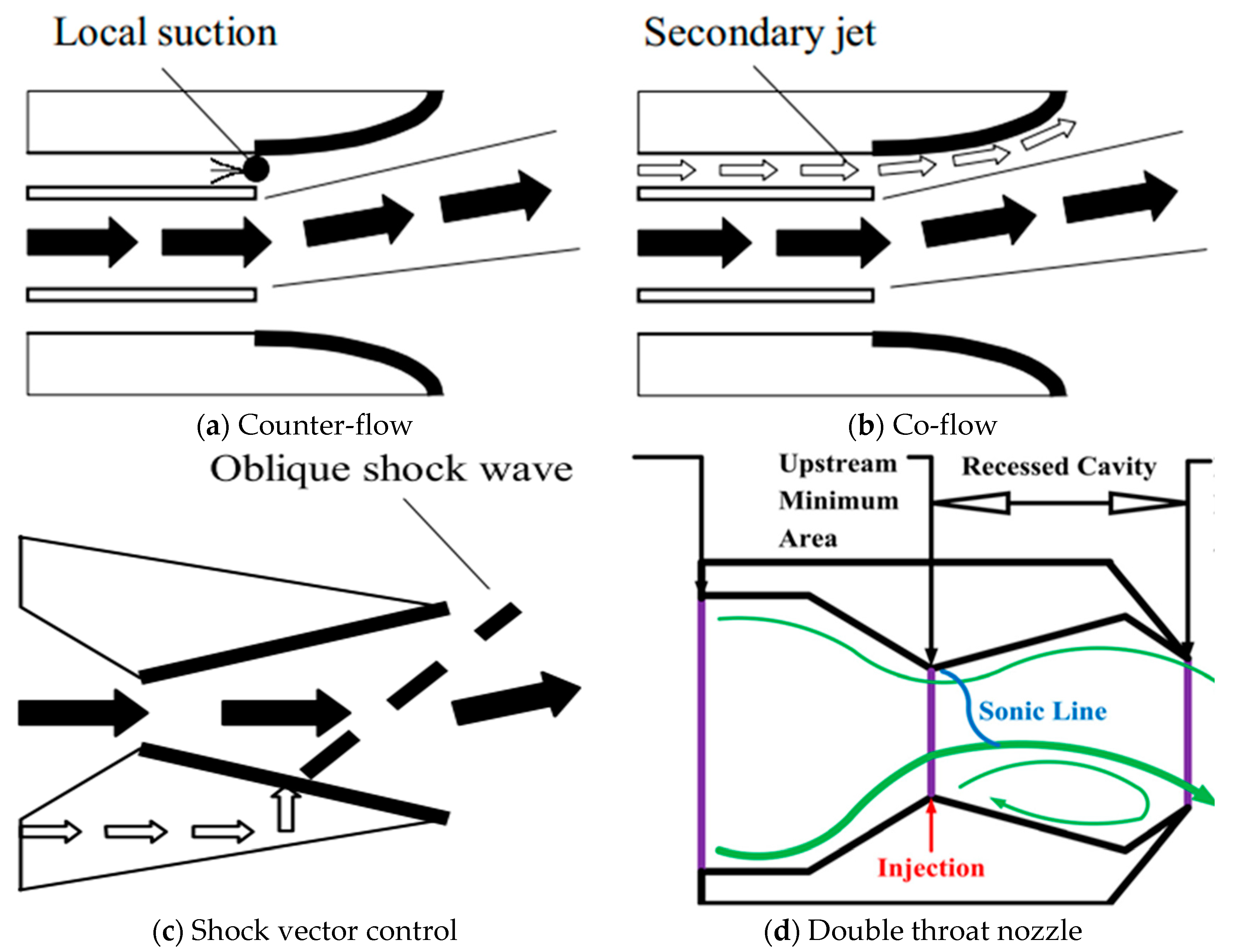
Figure 1. Sketch of different FTV methods. (a) Counter-flow, (b) Co-flow, (c) Shock vector control, (d) Double throat nozzle [5].
Aerospace 11 00369 g001
Figure 2. Geometry of OSVC.
Aerospace 11 00369 g002
Figure 3. Grid and boundary conditions.
Aerospace 11 00369 g003
Figure 4. Comparison of pressure distribution on OSVC upper surface.
Aerospace 11 00369 g004
Figure 5. Numerical schlieren and experimental comparison.
Aerospace 11 00369 g005
Figure 6. Mach contour of OSVC.
Aerospace 11 00369 g006
Figure 7. ESVC geometry.
Aerospace 11 00369 g007
Figure 8. Zoom view of ESVC grid.
Aerospace 11 00369 g008
Figure 9. Vector performance comparison at different NPRs. (a) Vector angle, (b) Thrust coefficient and vector efficiency.
Aerospace 11 00369 g009
Figure 10. Density gradient contour of ESVC at NPR 4.6.
Aerospace 11 00369 g010
Figure 11. Mach contour gradient contour of ESVC at NPR 4.6.
Aerospace 11 00369 g011
Figure 12. Pressure distribution comparison of ESVC, OSVC, and BSVC.
Aerospace 11 00369 g012
Figure 13. Upper surface pressure distribution of ESVC varies with NPR.
Aerospace 11 00369 g013
Figure 14. Mach contour of ESVC and OSVC at NPR 4.6. (a) ESVC, (b) OSVC.
Aerospace 11 00369 g014
Figure 15. Pressure distribution for BSVC.
Aerospace 11 00369 g015
Figure 16. Ma contour and streamlines for BSVC at different NPRs. (a) NPR = 5.0, (b) NPR = 6.0.
Aerospace 11 00369 g016
Figure 17. Vector performance comparison at different SPRs. (a) Vector angle, (b) Vector efficiency and thrust coefficient.
Aerospace 11 00369 g017
Figure 18. Upper surface pressure distribution of ESVC varies with SPR.
Aerospace 11 00369 g018
Figure 19. Mach contour of ESVC at different SPRs. (a) SPR = 1.0, (b) SPR = 2.0.
Aerospace 11 00369 g019
Figure 20. Vector performance of ESVC varies with spacing. (a) Vector angle and vector efficiency, (b) Thrust coefficient.
Aerospace 11 00369 g020
Figure 21. Comparison of upper and lower surface pressure distributions of ESVC at different spacings. (a) l / l s = 3.0 8.0 , (b) l / l s = 8.0 12.0 .
Aerospace 11 00369 g021
Figure 22. Density gradient of ESVC at different spacings. (a) l / l s = 1.5 , (b) l / l s = 8.0 , (c) l / l s = 12.0 .
Aerospace 11 00369 g022
Figure 23. Ma and pressure at centerline for ESVC.
Aerospace 11 00369 g023
Table 1. Nozzle performance in different grids.
C f g δ p (°)
coarse0.9757.0
medium0.9727.42
fine0.9717.46
Exp0.9697.0
Disclaimer/Publisher’s Note: The statements, opinions and data contained in all publications are solely those of the individual author(s) and contributor(s) and not of MDPI and/or the editor(s). MDPI and/or the editor(s) disclaim responsibility for any injury to people or property resulting from any ideas, methods, instructions or products referred to in the content.