A Novel Explicit Canonical Dynamic Modeling Method for Multi-Rigid-Body Mechanisms Considering Joint Friction
Abstract
1. Introduction
2. Explicit Canonical Dynamic Modeling Theory
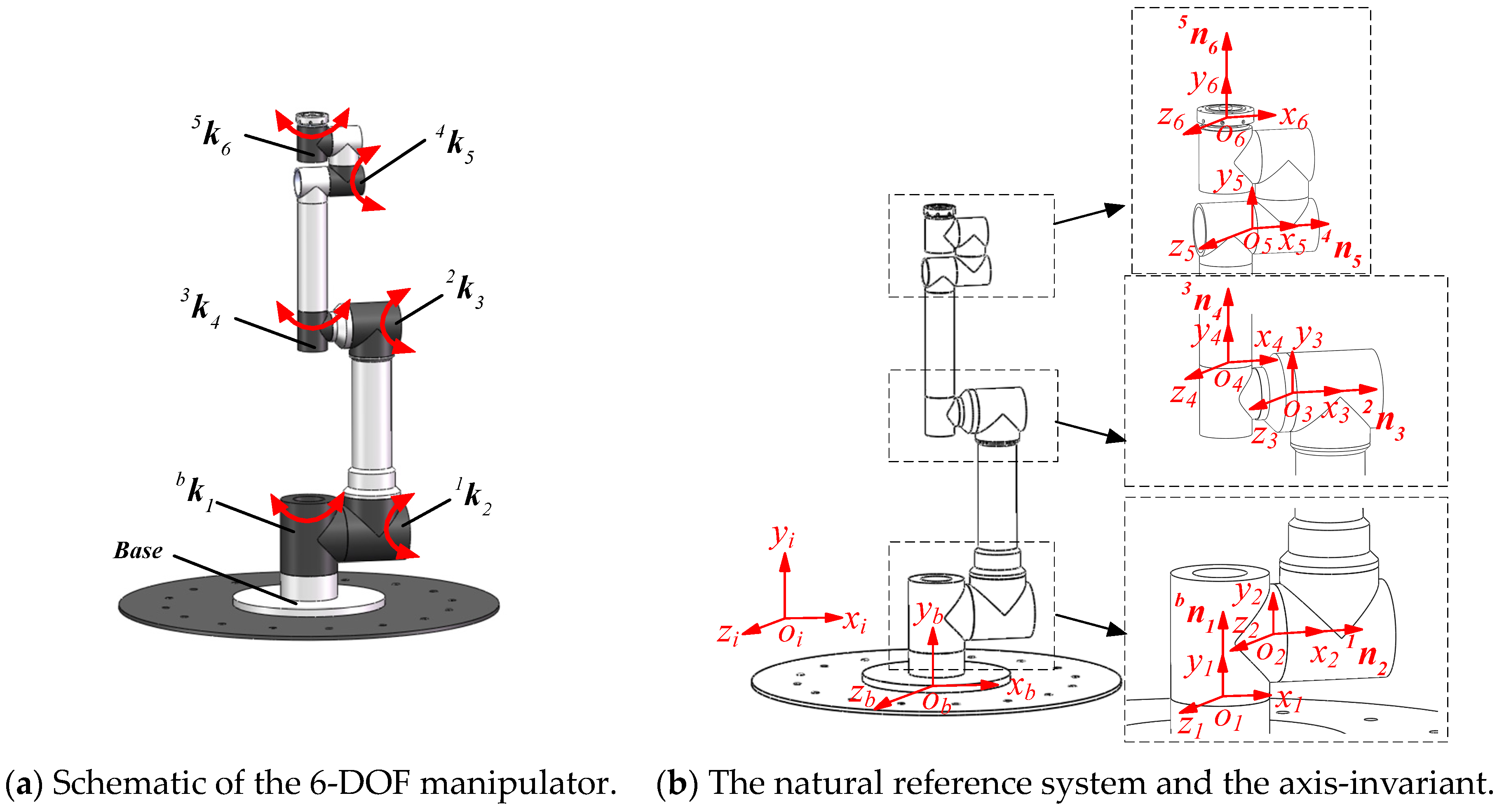
2.1. Kinematic Modeling
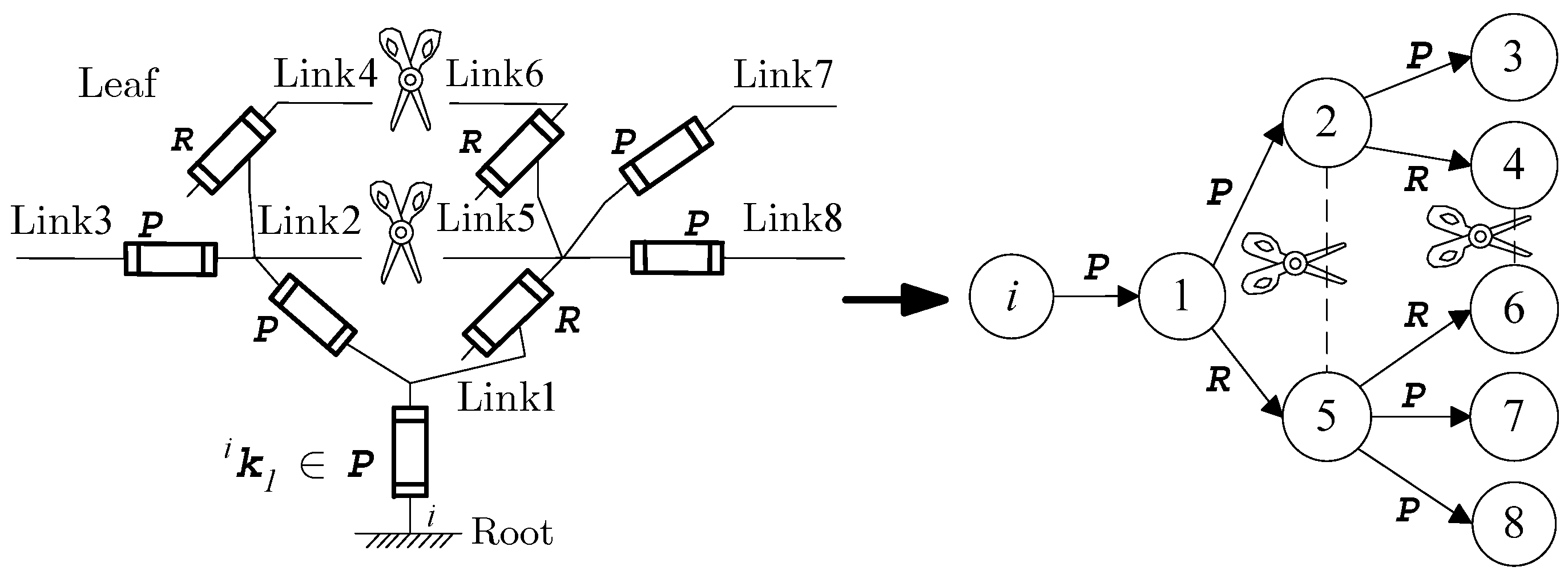
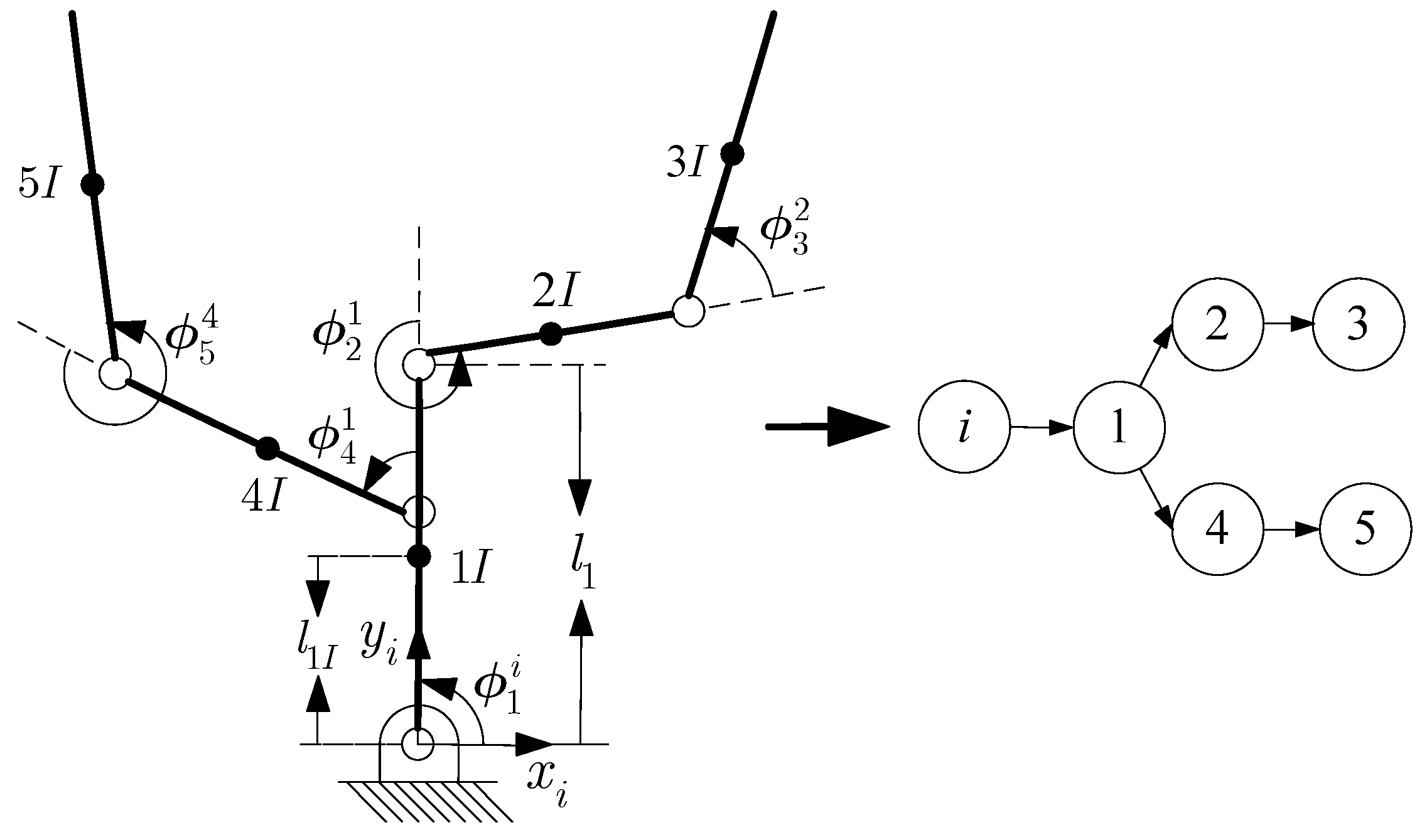
2.2. Ideal Dynamic Modeling of Tree-Chain Mechanisms without Considering Joint Friction
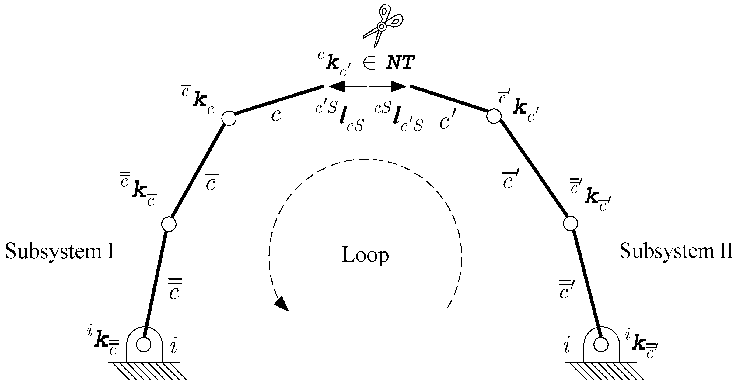
2.3. Ideal Dynamic Modeling of Closed-Chain Mechanisms without Considering Joint Friction
3. Joint Friction Modeling of Multi-Rigid-Body Mechanisms
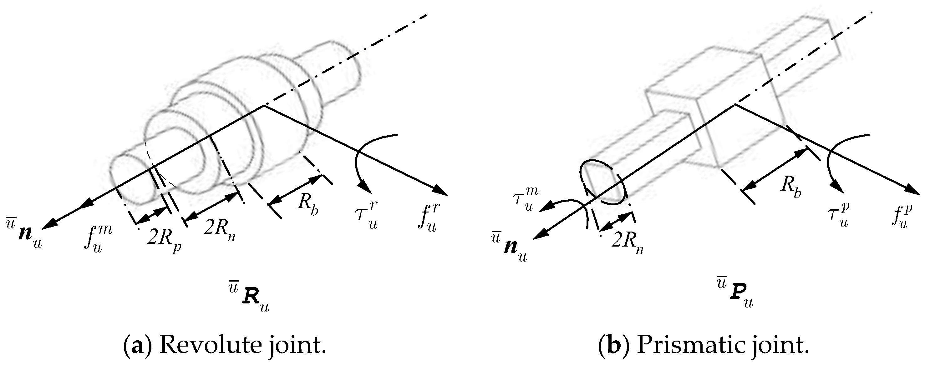
3.1. Solution of the Joint Constraint Force
3.2. Improvement of the Joint Constraint Force Solution Method
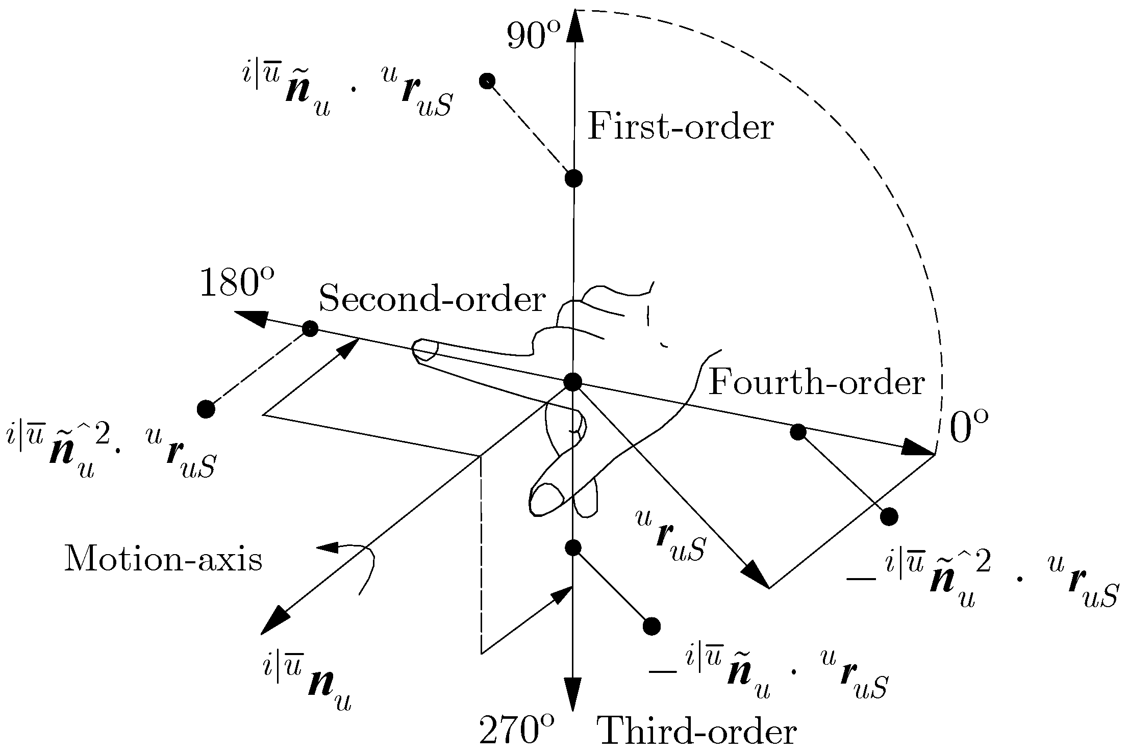
3.2.1. 3D Motion Screw
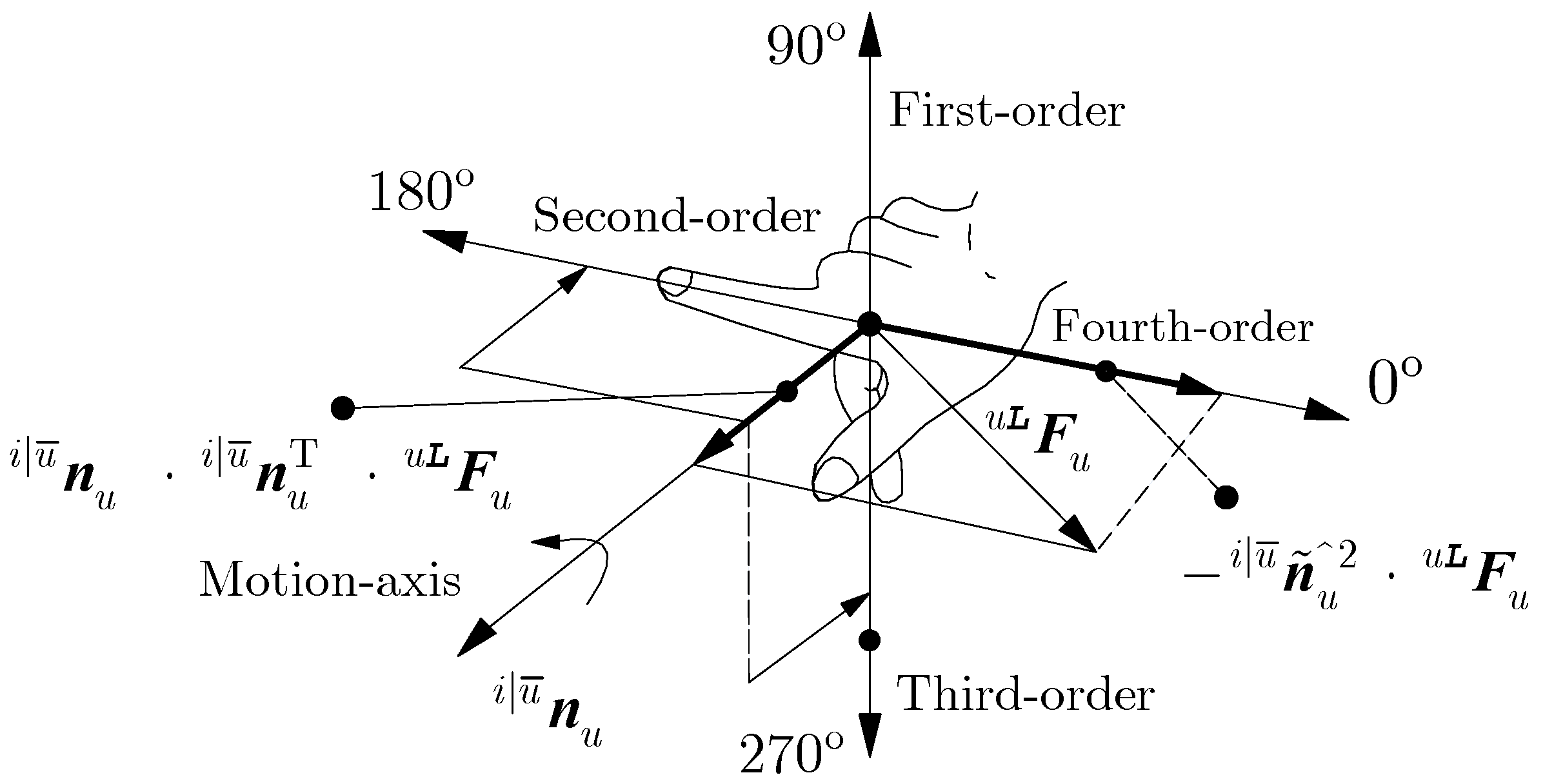
3.2.2. 3D Force Screw
3.3. Friction Model
3.3.1. Coulomb–Viscous Friction Model
3.3.2. Analysis of and
3.3.3. Stribeck Friction Model
4. Modeling and Solving of the Complete Dynamics of Multi-Rigid-Body Mechanisms
4.1. Complete Dynamic Modeling of Tree-Chain Mechanisms Considering Joint Friction
4.2. Complete Dynamic Modeling of Closed-Chain Mechanisms Considering Joint Friction
| Algorithm 1: Dynamic algorithm of multi-rigid-body mechanism considering joint friction. |
| 1: Initialization 2: analyze topological structure of mechanism and establish natural reference systems 3: repeat 4: compute inertia matrices and bias force vectors following Equations (19)–(22) 5: if (single chain or tree chain) 6: compute joint constraint forces and torques following Equations (39), (44), and (46) 7: compute joint normal forces and torques following Equation (47) 8: establish friction model following Equation (42) or Equation (52) 9: compute joint-generalized driving forces following Equation (54) 10: else (closed chain) 11: compute passive joint velocities following Equation (24) 12: compute joint-generalized external forces following Equations (25) and (26) 13: compute joint constraint forces and torques following Equations (39), (44), and (46) 14: compute joint normal forces and torques following Equation (47) 15: establish friction model following Equation (42) or Equation (52) 16: compute active joint-generalized driving forces following Equation (56) 17: until mechanism stops |
5. Case Study
5.1. Five-Axis Tree-Chain Mechanism
- (1)
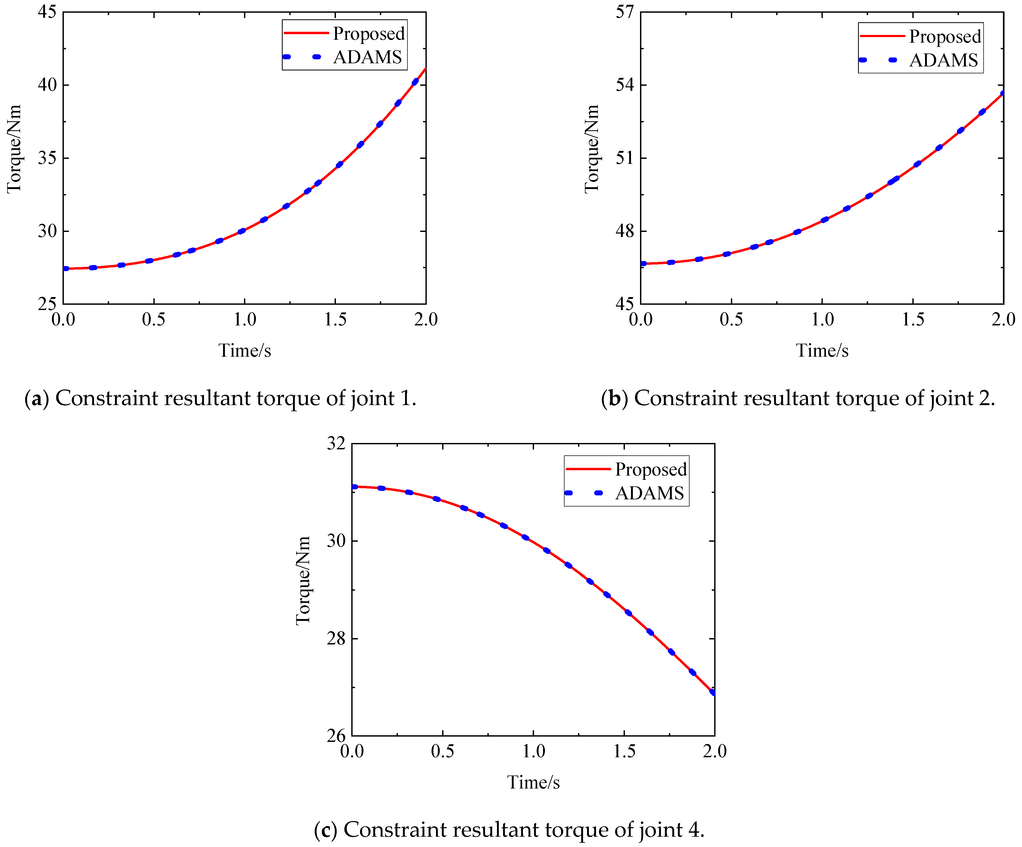
- All the joints in the five-axis tree-chain mechanism are revolute joints. The constraint torque vector equations of the mechanism can be obtained according to Equation (36) as follows:
- (2)
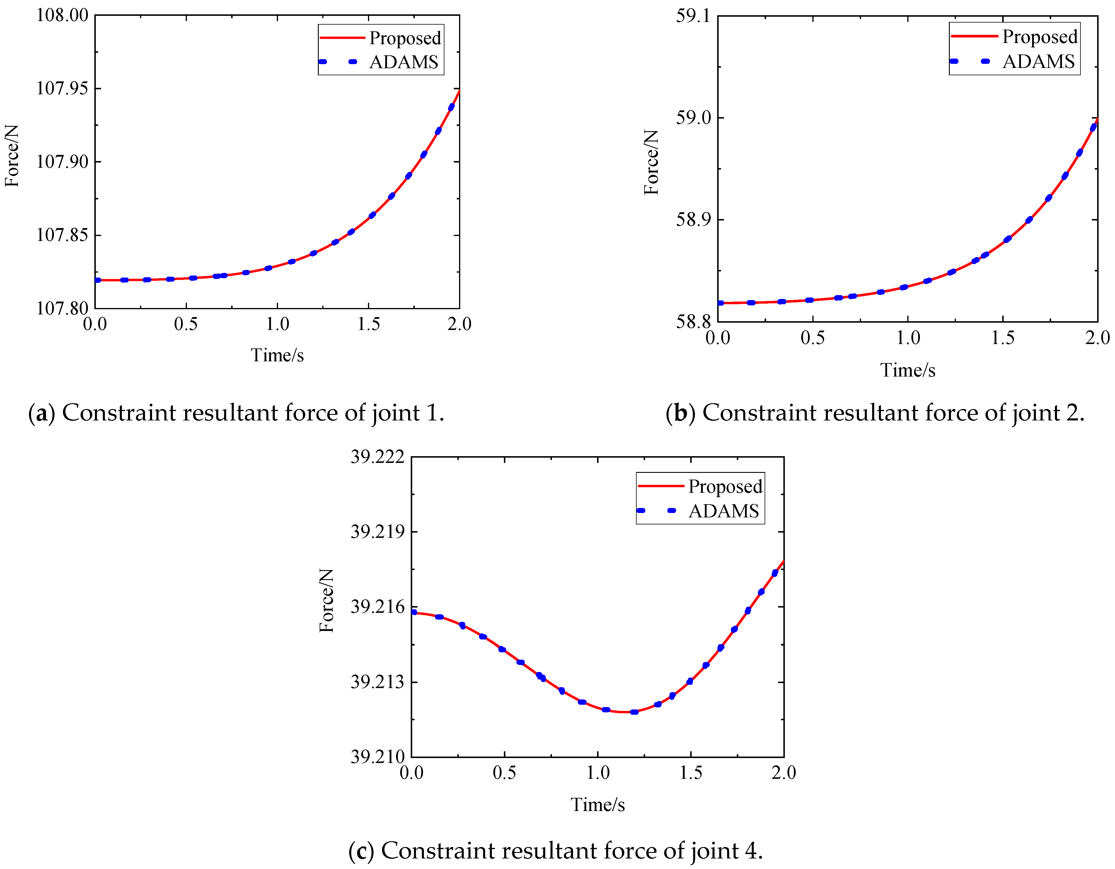
- The constraint force vector equations of the mechanism can be obtained according to Equations (43) and (45) as follows:
- (3)
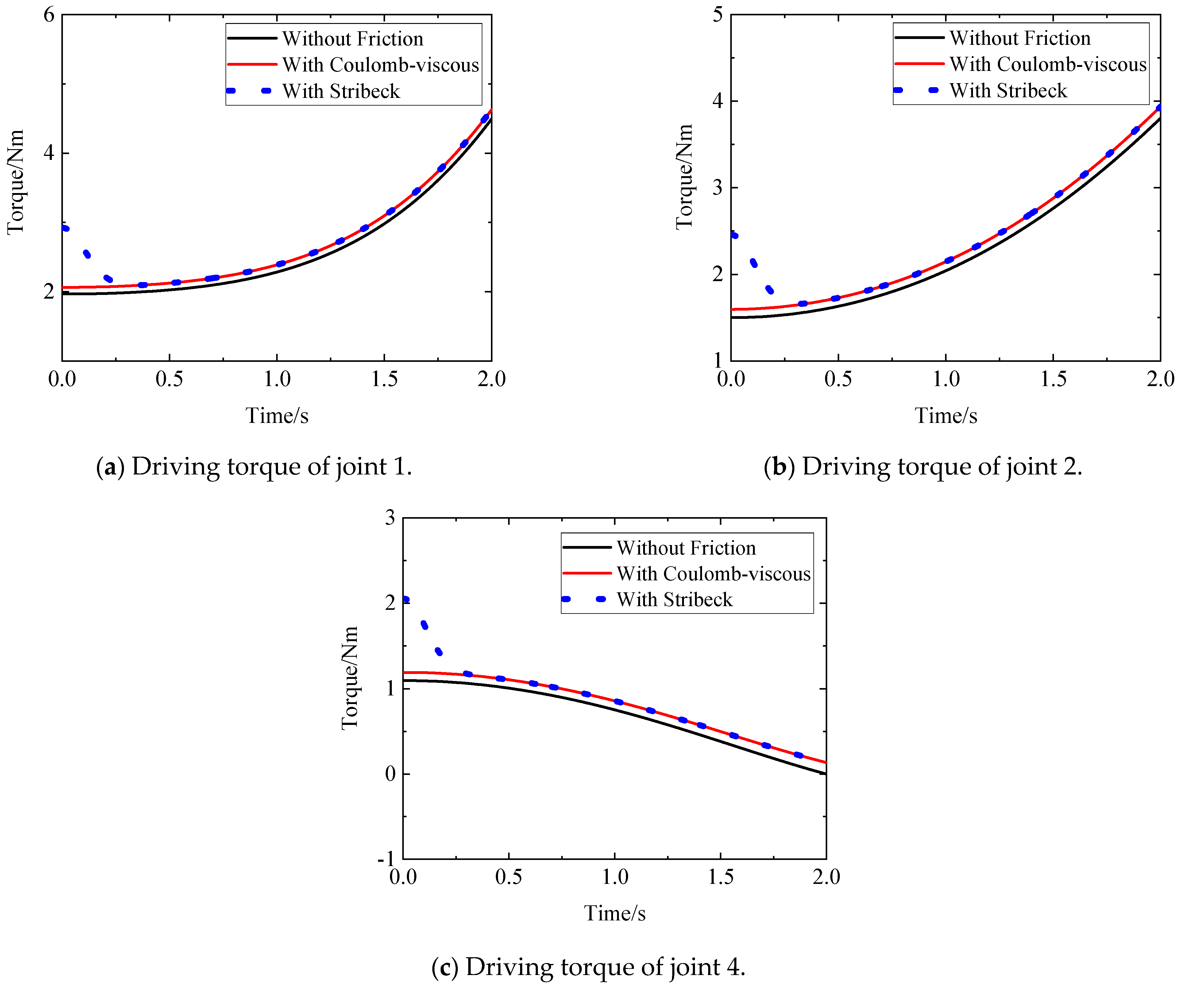
- According to the constraint force and constraint torque calculated using the above equations, the friction models of the five active joints can be obtained. Then, the generalized driving forces of the five active joints can be obtained according to Equation (54) as follows:
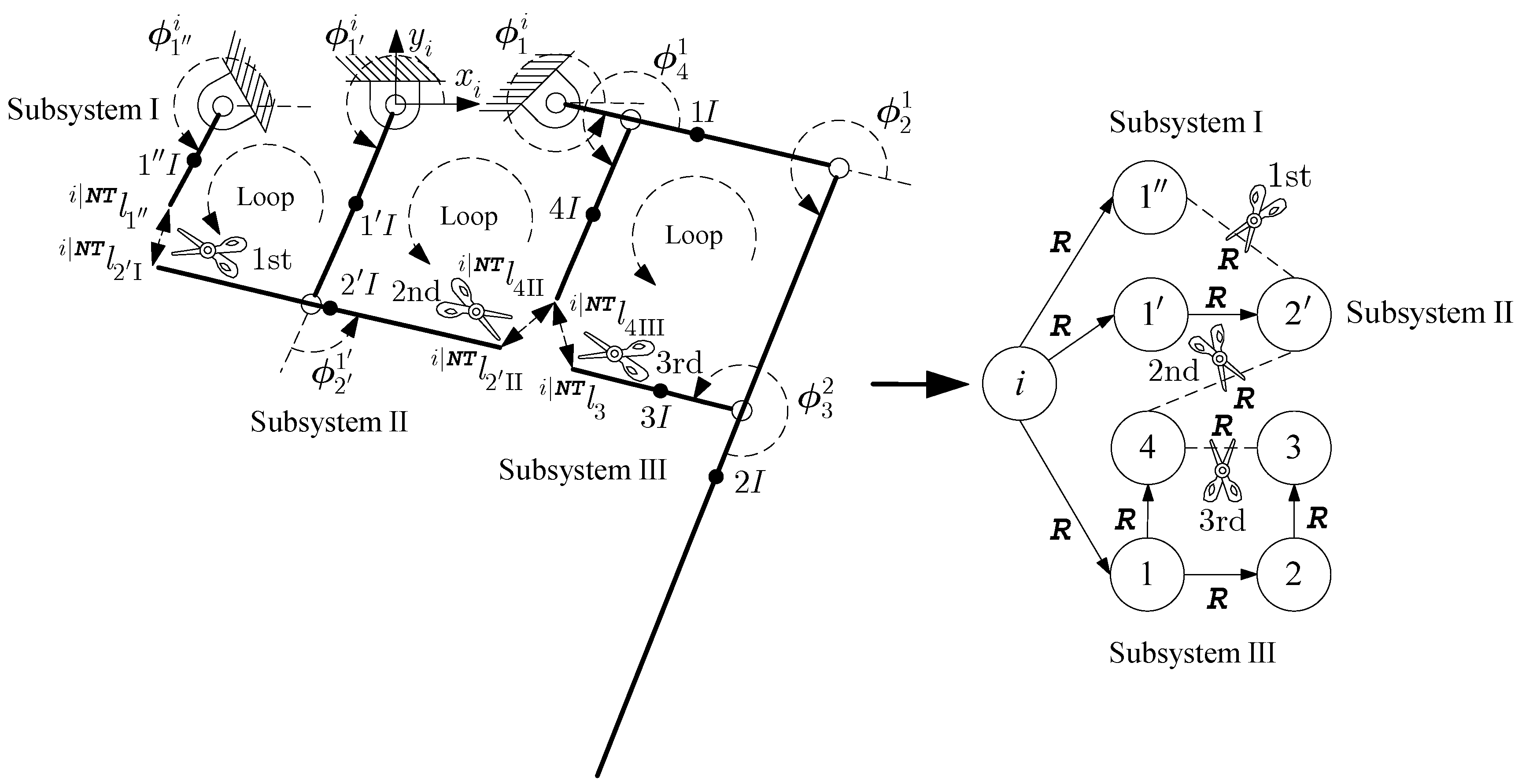
5.2. Three-Loop Closed-Chain Mechanism
- (1)
- The three-loop closed-chain mechanism contains three independent loops. Thus, we can obtain three kinematic constraint equations. The kinematic constraint equations of the mechanism can be obtained according to Equation (24) as follows:
- (2)
- The dynamic equations of Subsystem III can be obtained according to Equation (56) as follows:
- (3)
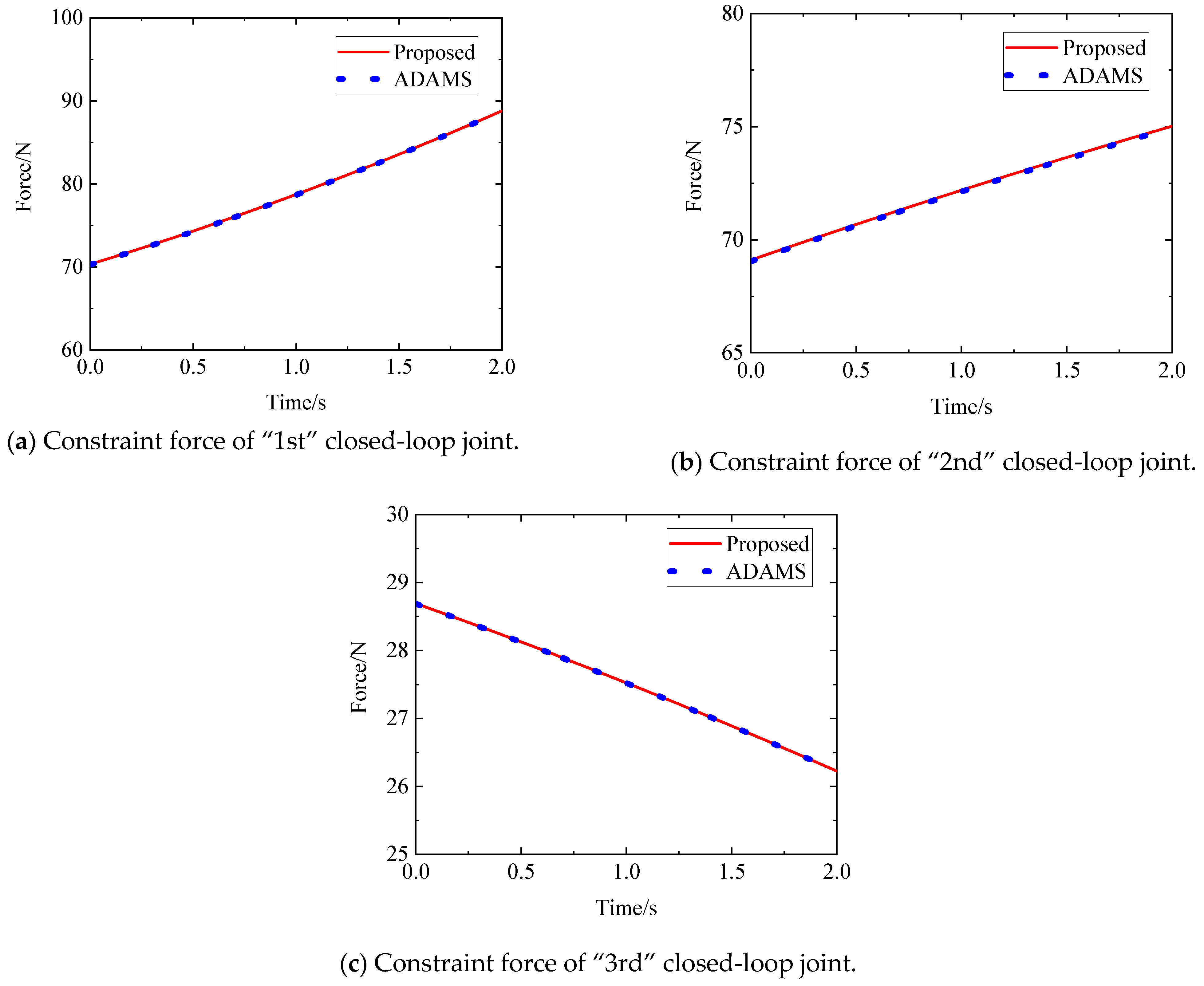
- The constraint force generated by the 2nd-cutting closed-loop joint can be calculated according to Equation (62). Therefore, Subsystem II becomes determinate. The dynamic equations of Subsystem II can be obtained according to Equation (56) as follows:
- (4)
- According to Equation (63), the constraint force generated by the 1st-cutting closed-loop joint can be calculated so that Subsystem I becomes determinate. The constraint torque vector equations and the constraint force vector equations of the active joint (1″) can be obtained according to Equation (38) as follows:
- (5)
- According to the constraint force and constraint torque calculated using the above equations, the friction model of the active joint (1″) can be obtained. Then, the driving torque of the active joint (1″) can be obtained according to Equation (56) as follows:where matrices , vectors , and vectors in Equations (62)–(65) are defined in Equations (A11)–(A31) in Appendix A.
6. Discussion
- ①
- Compared with the traditional Lagrangian calculation method, the proposed method can not only avoid the analysis of the system energy but also avoid the modeling of a large number of intermediate variables and complex partial derivative operations;
- ②
- Compared with the traditional Newton–Euler calculation method, the proposed method can avoid complex force analysis for each joint of the mechanism and a large number of intermediate variable calculations, can explicitly calculate the joint constraint force, and requires fewer constraint force equations;
- ③
- ①
- For modeling the kinematic constraint equation, two methods can be conducted to determine the explicit expression of the kinematic constraint equations, but Zhao’s method requires complex derivative operations and trigonometric function operations to derive many intermediate variables;
- ②
- For modeling the constraint force equation, both methods provide explicit expressions. However, when Zhao’s method is used to solve the constraint force vectors of different closed-chain mechanisms, complex derivative operations are necessary to deduce multiple intermediate variables. In addition, for Zhao’s method, two constraint axes need to be established when solving for the constraint force;
- ③
- For modeling the inertia matrix and bias force vector, both methods provide explicit expressions, but Zhao’s method uses the traditional Lagrangian method to derive them, which requires complex derivation and partial derivation operations of many intermediate variables.
7. Conclusions
- (1)
- The proposed explicit iterative constraint-force-solving method provides new insights for joint constraint force modeling. The proposed method has the advantages of low computational complexity, high modeling efficiency, and a relatively simple modeling process;
- (2)
- Like Zhao’s closed-chain dynamic method considering joint friction, the proposed method is also based on the derived joint constraint force to obtain the analytical form of the active joint friction model of closed-chain mechanisms, and the derived joint friction and constraint force are also decoupled. However, compared with that of Zhao’s method, the modeling process of the constraint force of the proposed method is simpler;
- (3)
- The proposed multi-rigid-body dynamic model considering joint friction only requires determining and replacing relevant parameters to achieve dynamic modeling and solution, reducing the difficulty of the engineering implementation.
Author Contributions
Funding
Data Availability Statement
Conflicts of Interest
Appendix A
References
- Liu, X.; Li, H.; Wang, J.; Cai, G. Dynamics analysis of flexible space robot with joint friction. Aerosp. Sci. Technol. 2015, 47, 164–176. [Google Scholar] [CrossRef]
- Liu, X.-F.; Li, H.-Q.; Chen, Y.-J.; Cai, G.-P. Dynamics and control of space robot considering joint friction. Acta Astronaut. 2015, 111, 1–18. [Google Scholar] [CrossRef]
- Hui, J.; Pan, M.; Zhao, R.; Luo, L.; Wu, L. The closed-form motion equation of redundant actuation parallel robot with joint friction: An application of the Udwadia–Kalaba approach. Nonlinear Dyn. 2018, 93, 689–703. [Google Scholar] [CrossRef]
- Zhang, Q.; Liu, X.; Cai, G. Dynamics and Control of a Flexible-Link Flexible-Joint Space Robot with Joint Friction. Int. J. Aeronaut. Space Sci. 2020, 22, 415–432. [Google Scholar] [CrossRef]
- Zhao, L.; Zhao, X.-H.; Li, B.; Yang, Y.-W.; Liu, L. Nonlinear friction dynamic modeling and performance analysis of flexible parallel robot. Int. J. Adv. Robot. Syst. 2020, 17. [Google Scholar] [CrossRef]
- Ciliz, M.K. Adaptive control of robot manipulators with neural network based compensation of frictional uncertainties. Robotica 1999, 23, 159–167. [Google Scholar] [CrossRef]
- Grotjahn, M.; Heimann, B.; Abdellatif, H. Identification of Friction and Rigid-Body Dynamics of Parallel Kinematic Structures for Model-Based Control. Multibody Syst. Dyn. 2004, 11, 273–294. [Google Scholar] [CrossRef]
- Karbasizadeh, N.; Zarei, M.; Aflakian, A.; Masouleh, M.T.; Kalhor, A. Experimental dynamic identification and model feed-forward control of Novint Falcon haptic device. Mechatronics 2018, 51, 19–30. [Google Scholar] [CrossRef]
- Jianning, F.; Hanjing, Z.; Wenkang, H. Modeling and Compensation of Non-linear Friction for Spatial Robotic Arm Joint. J. Mech. Transm. 2014, 38, 28–32. [Google Scholar]
- Reynoso-Mora, P.; Chen, W.; Tomizuka, M. A convex relaxation for the time-optimal trajectory planning of robotic manipulators along predetermined geometric paths. Optim. Control Appl. Methods 2016, 37, 1263–1281. [Google Scholar] [CrossRef]
- Guo, F.; Cheng, G.; Pang, Y. Explicit dynamic modeling with joint friction and coupling analysis of a 5-DOF hybrid polishing robot. Mech. Mach. Theory 2021, 167, 104509. [Google Scholar] [CrossRef]
- Wu, J.; Li, W.; Xiong, Z. Identification of robot dynamic model and joint frictions using a baseplate force sensor. Sci. China Technol. Sci. 2021, 65, 1–11. [Google Scholar] [CrossRef]
- Kostic, D.; de Jager, B.; Steinbuch, M. Modeling and Identification for Robot Motion Control, Robotics Automation Handbook; CRC Press: Boca Raton, FL, USA, 2004; Available online: https://research.tue.nl/en/publications/modeling-and-identification-for-robot-motion-control (accessed on 16 March 2024).
- Li, Y. Dynamic Modeling with Joint Friction and Research on the Inertia Coupling Property of a 5-PSS/UPU Parallel Manipulator. JMechE 2019, 55, 43–52. [Google Scholar] [CrossRef]
- Wu, G.; Caro, S.; Bai, S.; Kepler, J. Dynamic modeling and design optimization of a 3-DOF spherical parallel manipulator. Robot. Auton. Syst. 2014, 62, 1377–1386. [Google Scholar] [CrossRef]
- Yen, P.-L.; Lai, C.-C. Dynamic modeling and control of a 3-DOF Cartesian parallel manipulator. Mechatronics 2009, 19, 390–398. [Google Scholar] [CrossRef]
- Walker, M.W.; Orin, D.E. Efficient Dynamic Computer Simulation of Robotic Mechanisms. J. Dyn. Syst. Meas. Control 1982, 104, 205–211. [Google Scholar] [CrossRef]
- Featherstone, R. Rigid Body Dynamics Algorithms; Springer Science and Business Media LLC: Dordrecht, The Netherlands, 2008. [Google Scholar]
- Uicker, J.J. History of Multibody Dynamics in the U.S. J. Comput. Nonlinear Dyn. 2016, 11, 060302. [Google Scholar] [CrossRef]
- Li, C.-J. A New Lagrangian Formulation of Dynamics for Robot Manipulators. J. Dyn. Syst. Meas. Control Eng. Pract. 1989, 111, 559–566. [Google Scholar] [CrossRef]
- Siciliano, B.; Sciavicco, L.; Villani, L. Oriolo, Robotics: Modelling, Planning and Control; Springer: Berlin/Heidelberg, Germany, 2011; Available online: https://link.springer.com/book/10.1007/978-1-84628-642-1 (accessed on 16 March 2024).
- Yang, Y.; Ju, H.; Wang, K. An innovative joint-space dynamic theory for rigid multi-axis system—Part Ⅰ: Fundamental principles. Appl. Math. Model. 2022, 110, 28–44. [Google Scholar] [CrossRef]
- Wang, K.; Ju, H.; Yang, Y. An innovative joint-space dynamic theory for rigid multi-axis system—Part II: Canonical dynamic equations. Appl. Math. Model. 2022, 110, 475–492. [Google Scholar] [CrossRef]
- Wahrburg, A.; Klose, S.; Clever, D.; Groth, T.; Ding, H. Modeling Speed-, Load-, and Position-Dependent Friction Effects in Strain Wave Gears. In Proceedings of the 2018 IEEE International Conference on Robotics and Automation, Brisbane, Australia, 21–25 May 2018. [Google Scholar]
- Wolf, S.; Iskandar, M. Extending a Dynamic Friction Model with Nonlinear Viscous and Thermal Dependency for a Motor and Harmonic Drive Gear. In Proceedings of the 2018 IEEE International Conference on Robotics and Automation (ICRA), Brisbane, Australia, 21–25 May 2018; pp. 783–790. [Google Scholar]
- Iskandar, M.; Wolf, S. Dynamic friction model with thermal and load dependency: Modeling, compensation, and external force estimation. In Proceedings of the 2019 International Conference on Robotics and Automation (ICRA), Montreal, QC, Canada, 20–24 May 2019. [Google Scholar]
- Wojtyra, M. On Some Problems with Modeling of Coulomb Friction in Self-Locking Mechanisms. J. Comput. Nonlinear Dyn. 2016, 11, 011008. [Google Scholar] [CrossRef]
- Tu, X.; Zhao, P.; Zhou, Y.F. Parameter Identification of Static Friction Based on an Optimal Exciting Trajectory. In Proceedings of the 2017 3rd International Conference on Mechanical Engineering and Automation Science, Beijing, China, 25–26 March 2017. [Google Scholar]
- Bo, L.C.; Pavelescu, D. The friction-speed relation and its influence on the critical velocity of stick-slip motion. Wear 1982, 82, 277–289. [Google Scholar] [CrossRef]
- Haessig, D.A., Jr.; Friedland, B.J.J.o.D.S. Measurement, Control, on the Modeling and Simulation of Friction. J. Dyn. Sys. Meas. Control. Sep. 1991, 113, 354–362. [Google Scholar] [CrossRef]
- de Wit, C.C.; Olsson, H.; Astrom, K.; Lischinsky, P. A new model for control of systems with friction. IEEE Trans. Autom. Control 1995, 40, 419–425. [Google Scholar] [CrossRef]
- Gonthier, Y.; McPhee, J.; Lange, C.; Piedbœuf, J.-C. A Regularized Contact Model with Asymmetric Damping and Dwell-Time Dependent Friction. Multibody Syst. Dyn. 2004, 11, 209–233. [Google Scholar] [CrossRef]
- Ma, F.O. An extended bristle friction force model with experimental validation. Mech. Mach. Theory 2012, 56, 123–137. [Google Scholar]
- Harnoy, A.; Friedland, B. Dynamic Friction Model of Lubricated Surfaces for Precise Motion Control. Tribol. Trans. 1994, 37, 608–614. [Google Scholar] [CrossRef]
- Brown, P.; McPhee, J. A Continuous Velocity-Based Friction Model for Dynamics and Control with Physically Meaningful Parameters. J. Comput. Nonlinear Dyn. 2016, 11, 054502. [Google Scholar] [CrossRef]
- Andersson, S.; Söderberg, A.; Björklund, S. Friction models for sliding dry, boundary and mixed lubricated contacts. Tribol. Int. 2007, 40, 580–587. [Google Scholar] [CrossRef]
- Sherman, M.A.; Seth, A.; Delp, S.L. Simbody: Multibody dynamics for biomedical research. Procedia Iutam 2011, 2, 241–261. [Google Scholar] [CrossRef]
- Specker, T.; Buchholz, M.; Dietmayer, K.C.J. A New Approach of Dynamic Friction Modelling for Simulation and Observation. IFAC Proc. Vol. 2014, 47, 4523–4528. [Google Scholar] [CrossRef]
- Chacko, V.; Khan, Z. Dynamic Simulation of a Mobile Manipulator with Joint Friction. Tribol. Ind. 2017, 39, 152–167. [Google Scholar] [CrossRef][Green Version]
- Tsai, M.-S.; Yuan, W.-H. Inverse dynamics analysis for a 3-PRS parallel mechanism based on a special decomposition of the reaction forces. Mech. Mach. Theory 2010, 45, 1491–1508. [Google Scholar] [CrossRef]
- Abdellatif, H.; Heimann, B. Computational efficient inverse dynamics of 6-DOF fully parallel manipulators by using the Lagrangian formalism. Mech. Mach. Theory 2009, 44, 192–207. [Google Scholar] [CrossRef]
- Flores, P.; Ambrósio, J.; Claro, J.C.P.; Lankarani, H.M. Influence of the contact—Impact force model on the dynamic response of multi-body systems. Proc. Inst. Mech. Eng. Part K J. Multi-Body Dyn. 2006, 220, 21–34. [Google Scholar] [CrossRef]
- Ryu, J.-H.; Song, J.; Kwon, D.-S. A nonlinear friction compensation method using adaptive control and its practical application to an in-parallel actuated 6-DOF manipulator. Control Eng. Pr. 2001, 9, 159–167. [Google Scholar] [CrossRef]
- Shang, W.; Cong, S.; Zhang, Y. Nonlinear friction compensation of a 2-DOF planar parallel manipulator. Mechatronics 2008, 18, 340–346. [Google Scholar] [CrossRef]
- Shiau, T.-N.; Tsai, Y.-J.; Tsai, M.-S. Nonlinear dynamic analysis of a parallel mechanism with consideration of joint effects. Mech. Mach. Theory 2008, 43, 491–505. [Google Scholar] [CrossRef]
- Yuan, W.-H.; Tsai, M.-S. A novel approach for forward dynamic analysis of 3-PRS parallel manipulator with consideration of friction effect. Robot. Comput. Manuf. 2014, 30, 315–325. [Google Scholar] [CrossRef]
- Haug, E.J. Simulation of spatial multibody systems with friction. Mech. Based Des. Struct. Mach. 2017, 46, 347–375. [Google Scholar] [CrossRef]
- Verulkar, A.; Sandu, C.; Sandu, A.; Dopico, D. Simultaneous Optimal System and Controller Design for Multibody Systems with Joint Friction using Direct Sensitivities. arXiv 2023, arXiv:2312.15771. [Google Scholar]
- Ju, H. Axis-Invariant Based Multi-Axis Robot System Forward Kinematics Modeling and Solving Method. 2020. Available online: https://patents.justia.com/patent/20200055188 (accessed on 16 March 2024).
- Ju, H. Axis-Invariant Based Multi-Axis Robot Inverse Kinematics Modeling and Solving Method. 2020. Available online: https://patentscope2.wipo.int/search/en/detail.jsf?docId=WO2020034420 (accessed on 16 March 2024).
- Xiao, P.; Ju, H.; Li, Q.; Meng, J.; Chen, F. A New Fixed Axis-Invariant Based Calibration Approach to Improve Absolute Positioning Accuracy of Manipulators. IEEE Access 2020, 8, 134224–134232. [Google Scholar] [CrossRef]
- Guo, Z.; Ju, H.; Wang, K. An innovative joint-space explicit dynamics symbolic computation model for closed-chain mechanisms. Appl. Math. Model. 2023, 115, 34–55. [Google Scholar] [CrossRef]
- Ding, W.-H.; Deng, H.; Li, Q.-M.; Xia, Y.-M. Control-orientated dynamic modeling of forging manipulators with multi-closed kinematic chains. Robot. Comput. Manuf. 2014, 30, 421–431. [Google Scholar] [CrossRef]
- Chen, X.; Jiang, S.; Wang, T. Dynamic modeling and analysis of multi-link mechanism considering lubrication clearance and flexible components. Nonlinear Dyn. 2022, 107, 3365–3383. [Google Scholar] [CrossRef]
- Dehkordi, S. Dynamic analysis of flexible-link manipulator in underwater applications using Gibbs-Appell formulations. Ocean Eng. 2021, 241, 110057. [Google Scholar] [CrossRef]




| Type | Symbol | Description | Symbol | Description |
|---|---|---|---|---|
| Topology | Closed subtree of link u | Kinematic chain from i to l | ||
| Structure | Axis-invariant | Vector from to | ||
| Kinematic | Angular position along | Vector form of | ||
| Linear position along | Vector form of | |||
| Absolute angular velocity vector of joint l | Absolute angular acceleration vector of joint l | |||
| Absolute translational velocity vector of joint l | Absolute translational acceleration vector of joint l | |||
| Rotation matrix from to | 3D identity matrix | |||
| Dynamic | Mass of link k | Inertia tensor of link k | ||
| Inertial force matrix of revolute joint u | Bias force vector of revolute joint u | |||
| Inertial force matrix of prismatic joint u | Bias force vector of prismatic joint u | |||
| Resultant torque on axis except gravity | Resultant force on axis except gravity | |||
| Driving torque on axis | Driving force on axis | |||
| Mathematical operation | Exponent operator | Transpose operator | ||
| Derivative operator | Second derivative operator | |||
| Cross-product operator | Projection operator |
| Parameter | Symbol | Value |
|---|---|---|
| Axis-invariant | , , , , | [0 0 1]T |
| Initial linear position | ; ; | [−0.4 0 0]T; [0.6 1.0392 0]T; |
| ; | [−0.2 0 0]T; [0.6 −1.0392 0]T | |
| Central position of link mass | ;; | [−0.2 0 0]T; [0.3 0.5196 0]T; |
| ;; | [0.3 −0.5196 0]T; [0.3 −0.5196 0]T; | |
| [0.3 0.5196 0]T | ||
| Link mass | 1 kg | |
| , | 3 kg | |
| , | 2 kg | |
| Link MOI | diag(0.002, 0.01, 0.01) kg·m2 | |
| , | diag(0.008, 0.06, 0.06) kg·m2 | |
| , | diag(0.005, 0.04, 0.04) kg·m2 | |
| Gravitational acceleration | [0 0 −9.8]T m/s2 | |
| Driving angular acceleration | , , , , | 0.2 rad/s2 |
| Coulomb friction coefficient | , , , , | 0.005 |
| Viscous friction coefficient | , , , , | 0.01 |
| Static friction coefficient | , , , , | 0.05 |
| Stribeck velocity | , , , , | 0.03 |
| Parameter | Symbol | Value |
|---|---|---|
| Axis-invariant | , , , , , , | [0 0 1]T |
| Initial linear position | ; | [0.0737 −0.0676 0]T; [−0.0451 −0.0217 0]T; |
| ; ; | [−0.0375 0.0249 0]T; [0.0368 −0.0338 0]T; | |
| ; ; | [−0.0457 −0.0306 0]T; [−0.0079 −0.0544 0]T; | |
| ; ; | [0.049 −0.01 0]T; [−0.049 0.01 0]T; | |
| [−0.0069 −0.0445 0]T; | ||
| Central position of the link mass | ; ; | [0.0369 −0.0338 0]T; [−0.0451 −0.0217 0]T; |
| ; ; | [−0.0187 0.0124 0]T; [−0.0229 −0.0153 0]T; | |
| ; ; | [−0.0039 −0.0272 0]T; [0 0 0]T; | |
| [−0.0034 −0.0222 0]T | ||
| Link mass | , , | 2 kg |
| , | 1 kg | |
| , | 1.2 kg | |
| Link MOI | , , | diag(0.005, 0.04, 0.04) kg·m2 |
| , | diag(0.002, 0.01, 0.01) kg·m2 | |
| , | diag(0.003, 0.02, 0.02) kg·m2 | |
| Gravitational acceleration | [0 −9.8 0]T m/s2 | |
| Driving angular velocity | 0.1 rad/s | |
| Coulomb friction coefficient | 0.05 | |
| Viscous friction coefficient | 0.01 | |
| Static friction coefficient | 0.2 | |
| Stribeck velocity | 0.1 |
Disclaimer/Publisher’s Note: The statements, opinions and data contained in all publications are solely those of the individual author(s) and contributor(s) and not of MDPI and/or the editor(s). MDPI and/or the editor(s) disclaim responsibility for any injury to people or property resulting from any ideas, methods, instructions or products referred to in the content. |
© 2024 by the authors. Licensee MDPI, Basel, Switzerland. This article is an open access article distributed under the terms and conditions of the Creative Commons Attribution (CC BY) license (https://creativecommons.org/licenses/by/4.0/).
Share and Cite
Guo, Z.; Ju, H.; Wang, K. A Novel Explicit Canonical Dynamic Modeling Method for Multi-Rigid-Body Mechanisms Considering Joint Friction. Aerospace 2024, 11, 368. https://doi.org/10.3390/aerospace11050368
Guo Z, Ju H, Wang K. A Novel Explicit Canonical Dynamic Modeling Method for Multi-Rigid-Body Mechanisms Considering Joint Friction. Aerospace. 2024; 11(5):368. https://doi.org/10.3390/aerospace11050368
Chicago/Turabian StyleGuo, Zhenhao, Hehua Ju, and Kaimeng Wang. 2024. "A Novel Explicit Canonical Dynamic Modeling Method for Multi-Rigid-Body Mechanisms Considering Joint Friction" Aerospace 11, no. 5: 368. https://doi.org/10.3390/aerospace11050368
APA StyleGuo, Z., Ju, H., & Wang, K. (2024). A Novel Explicit Canonical Dynamic Modeling Method for Multi-Rigid-Body Mechanisms Considering Joint Friction. Aerospace, 11(5), 368. https://doi.org/10.3390/aerospace11050368


