
Dynamic Analysis of Three-Rotor System with Hollow Shaft under Clutch Misalignment


Abstract
1. Introduction
2. Modeling of the Three-Rotor-Bearing System
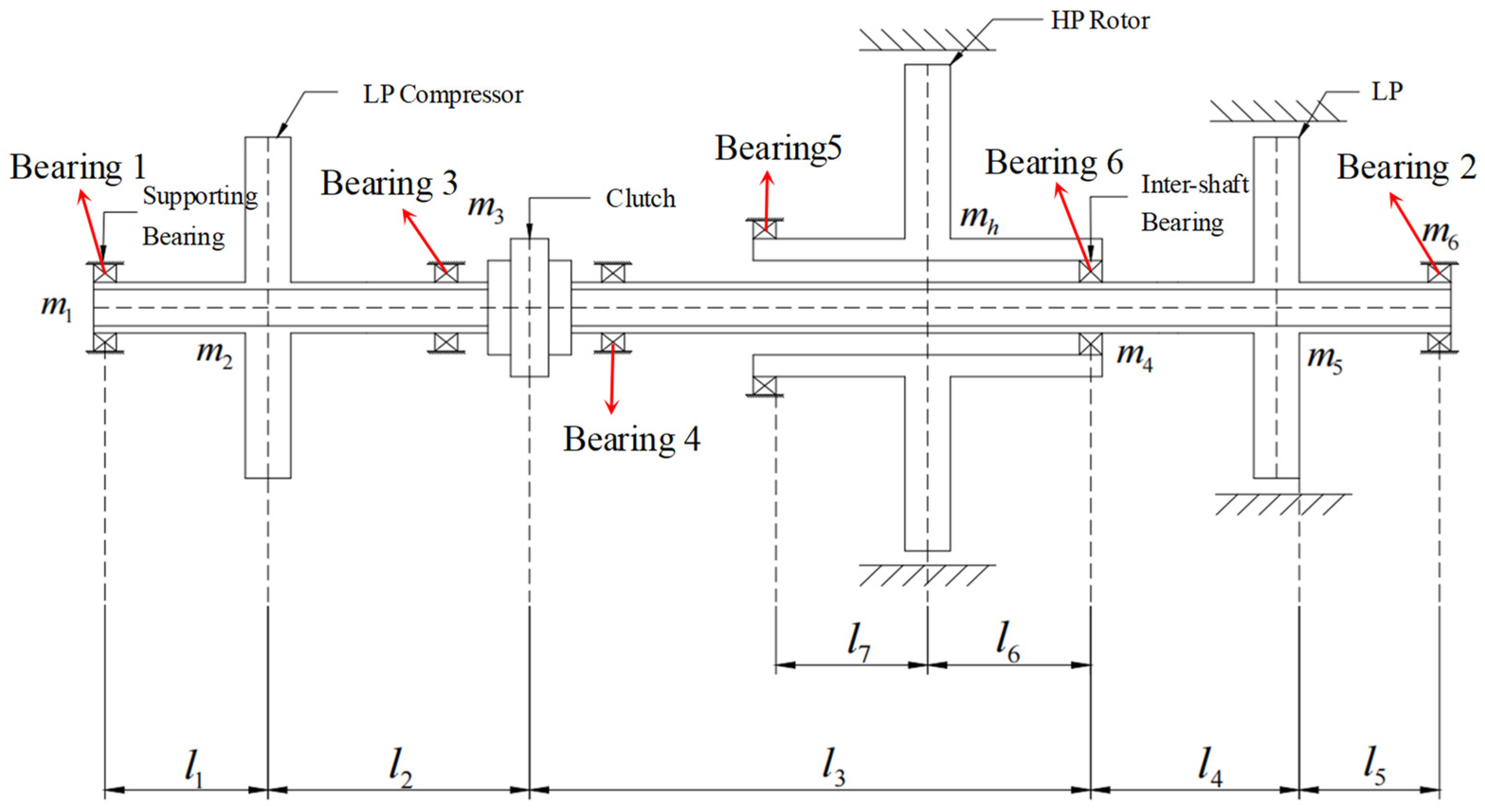
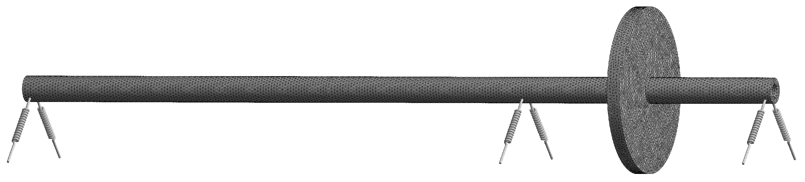
2.1. Physical Model of Three-Rotor-Bearing System
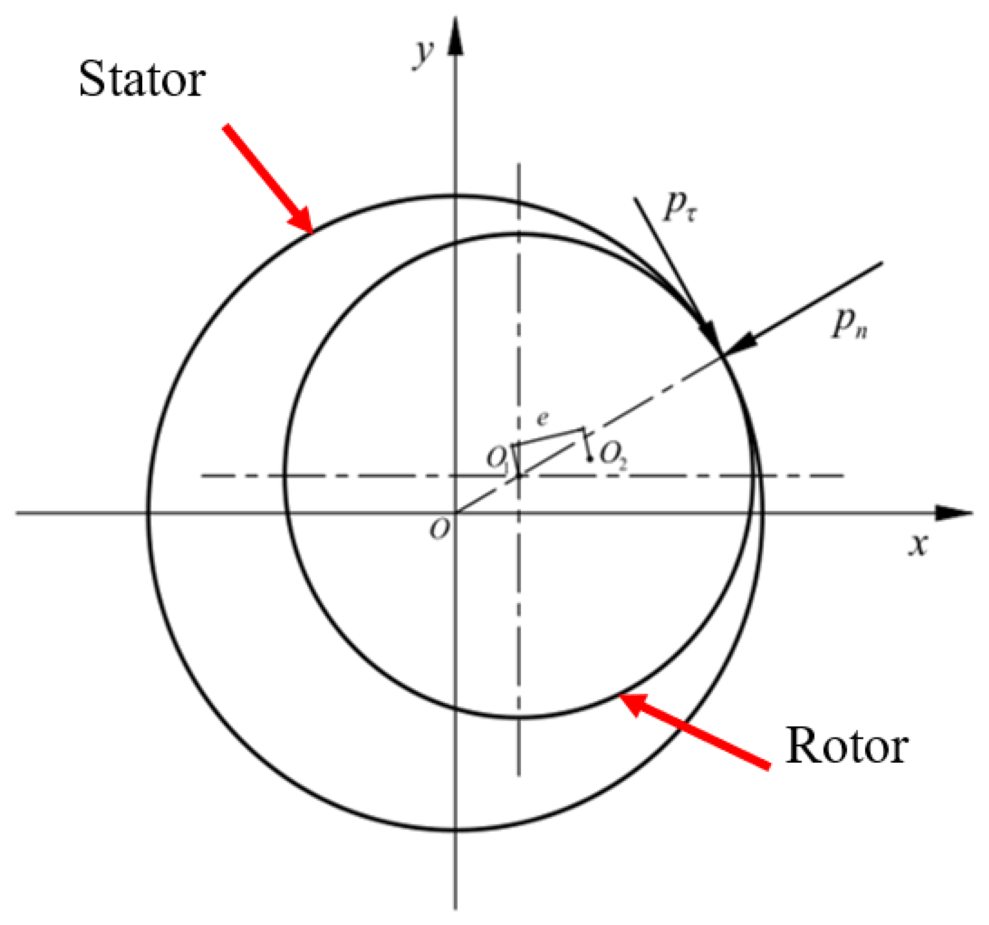
2.2. Contact Model of the Rotor and the Stator
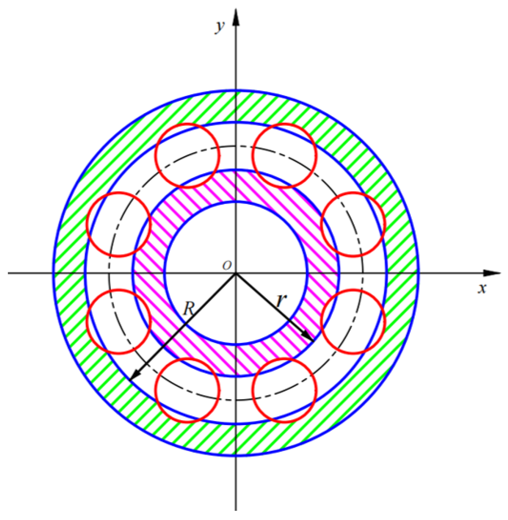
2.3. Modeling of Inter-Shaft Bearing
- (a)
- Ignore the friction and the relative sliding between the rolling element and the inner raceway and the outer raceway.
- (b)
- The rolling element and the inner and outer rings only have a radial flexible force that satisfies the Hertz contact theory.
- (c)
- The rolling elements are evenly arranged and spaced equally between the inner and outer rings.
- (d)
- The inner ring and outer ring of the bearing are rigidly connected to the shafts, with no relative sliding.
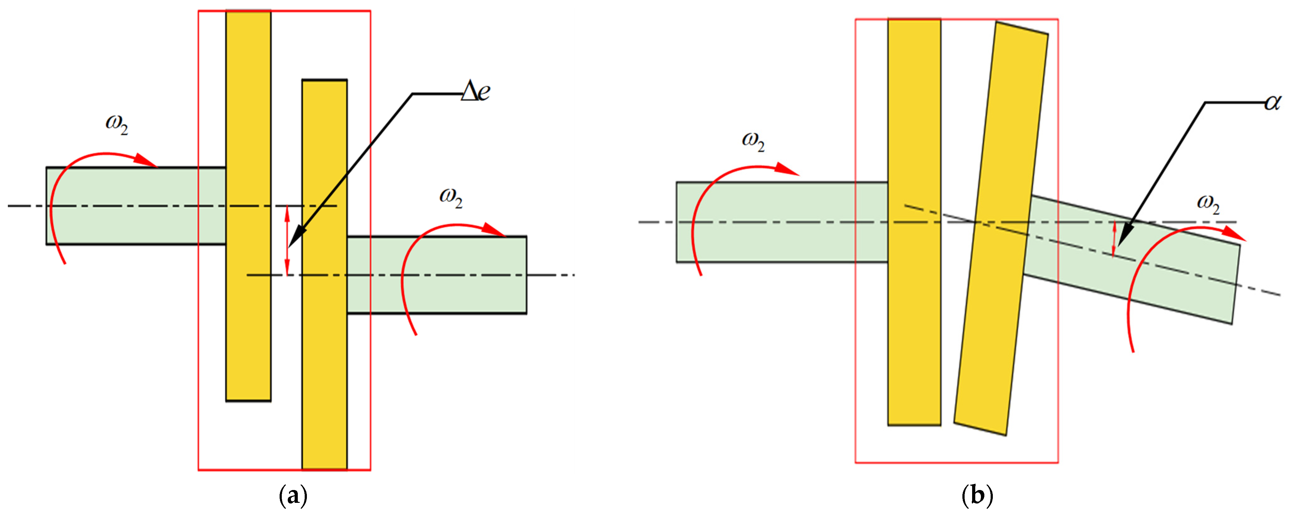
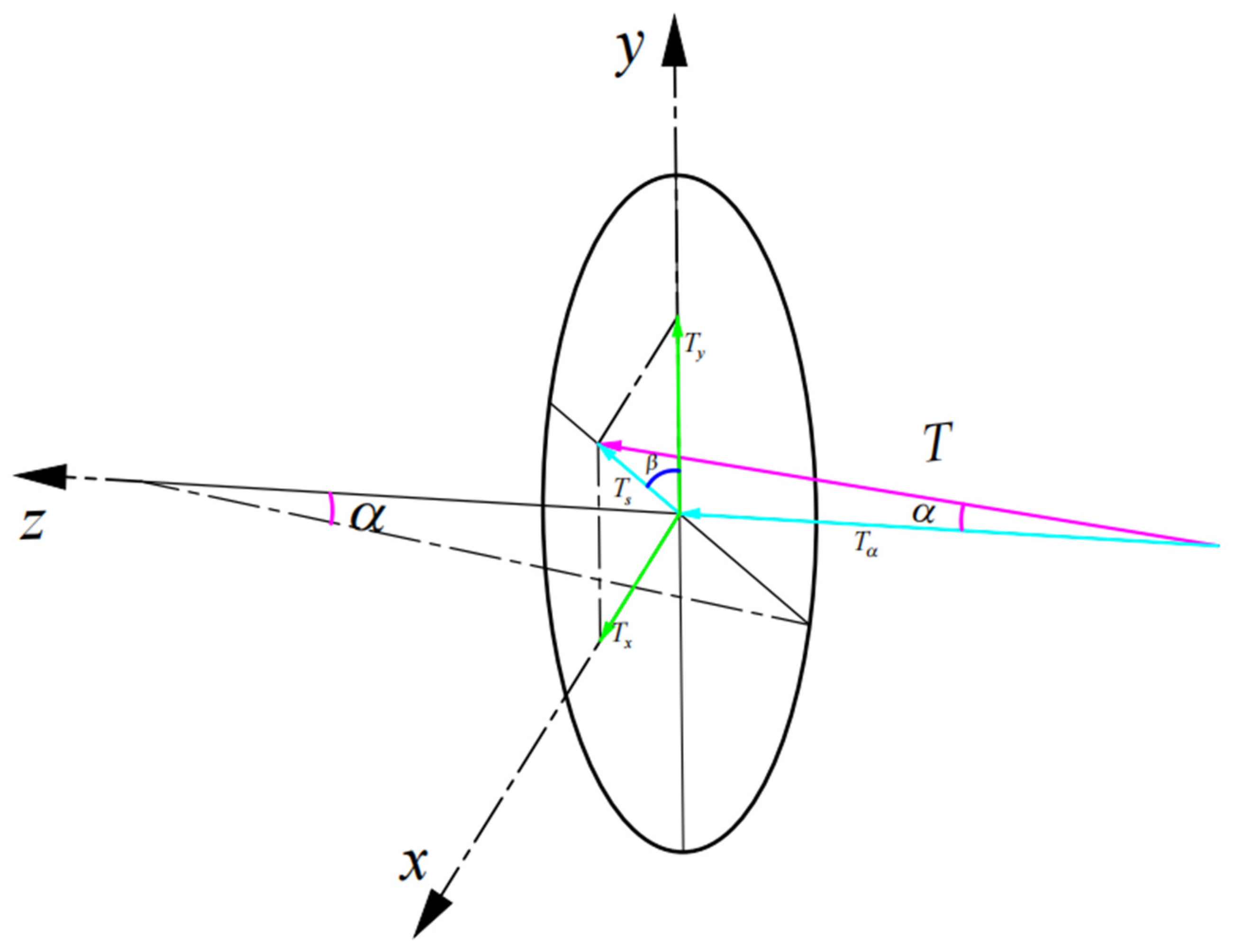
2.4. Modeling of Clutch Misalignment
2.5. Equation of Motion for the Three-Rotor System
3. Analysis of Fault Features
3.1. LP Compressor
3.2. LP Turbine
3.3. HP Rotor
3.4. Characteristic Frequency
4. Influencing Factors of Dynamic Characteristic for Multi-Rotor System
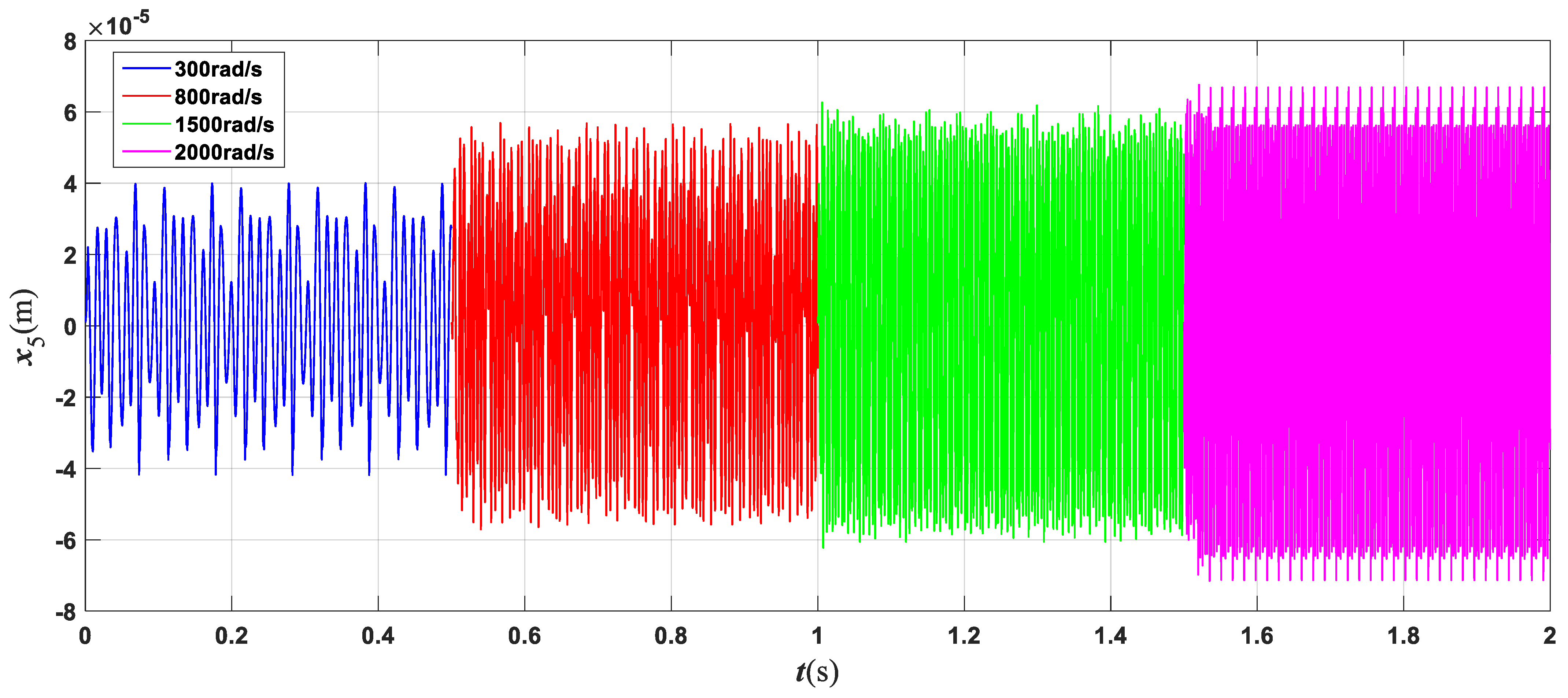
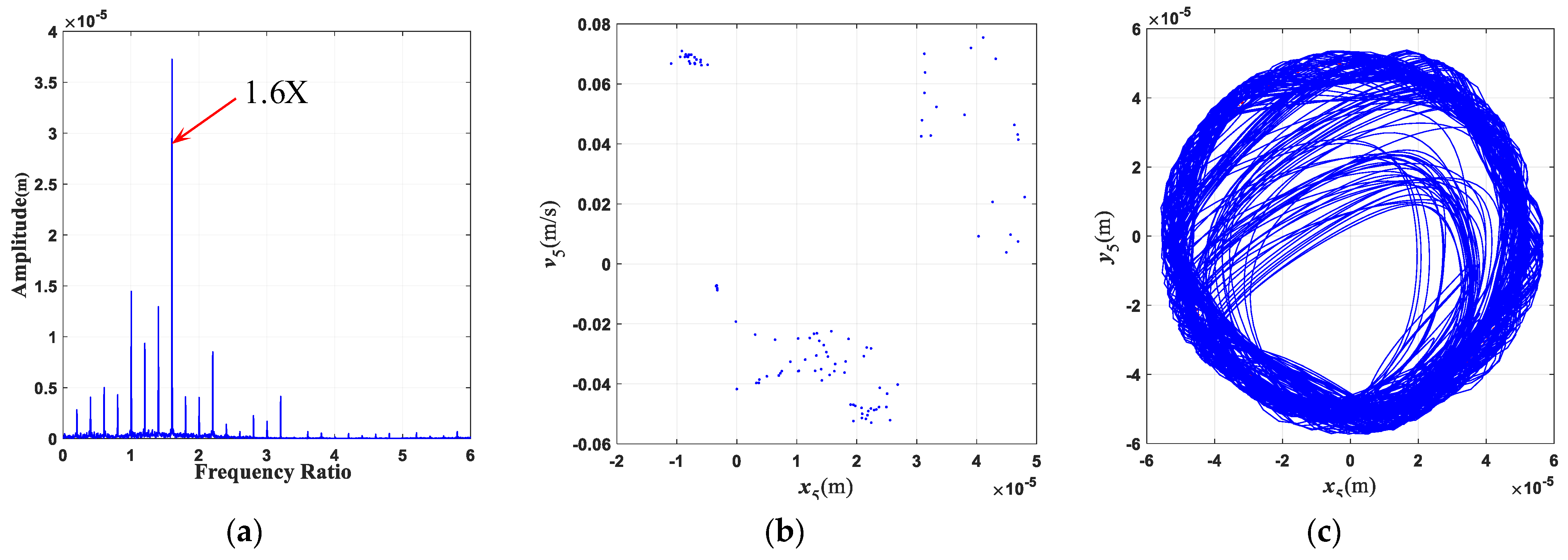
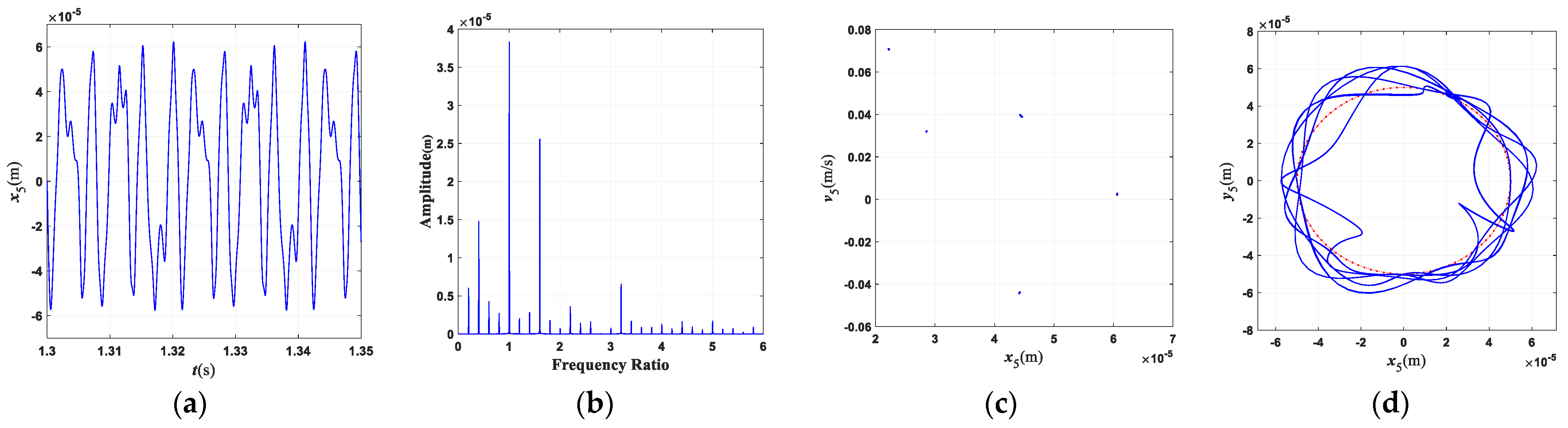
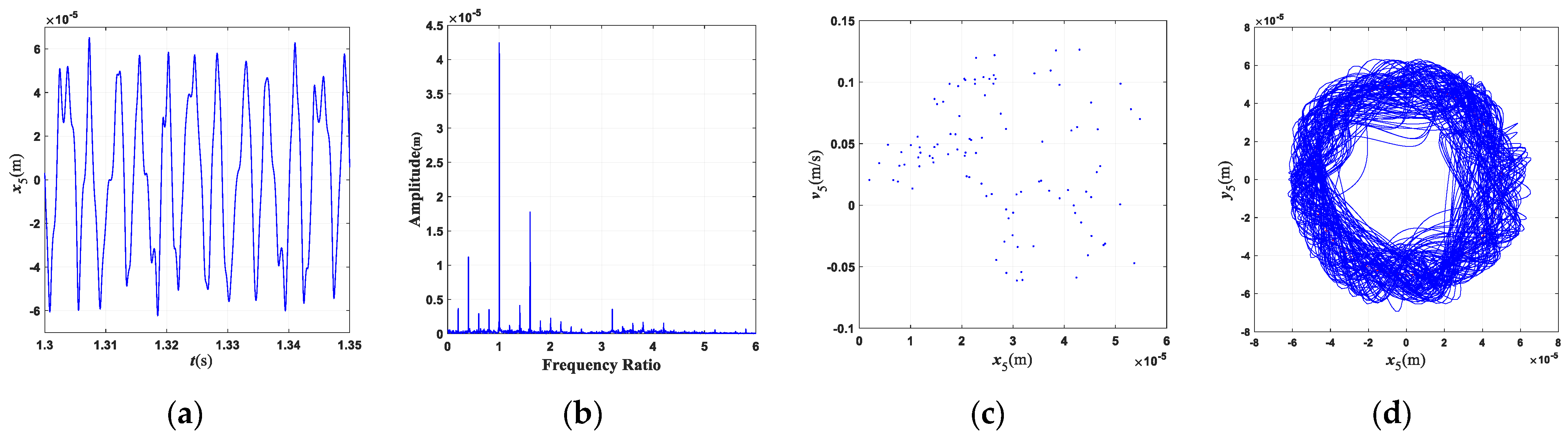
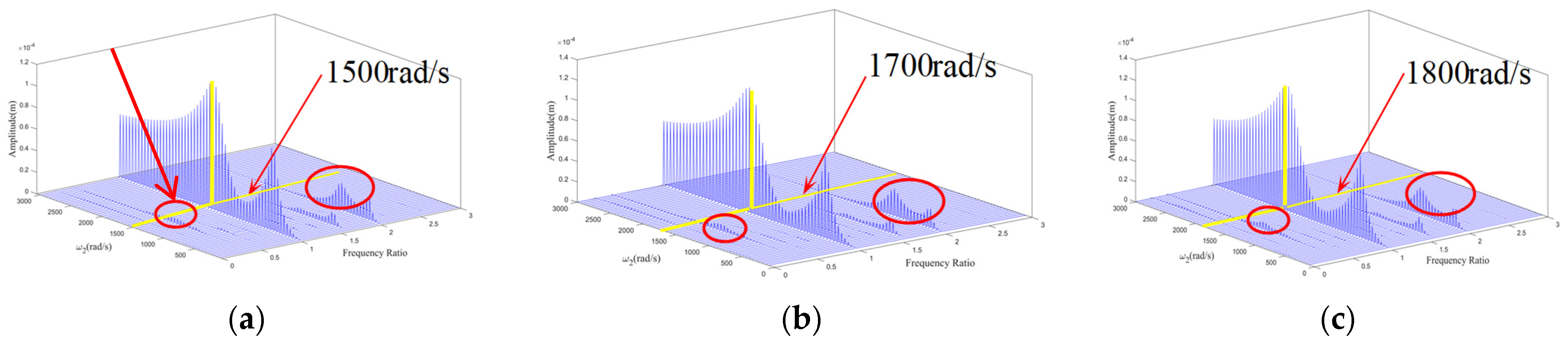
4.1. Influence of Rotational Speed
4.2. Influence of Misalignment Parameters
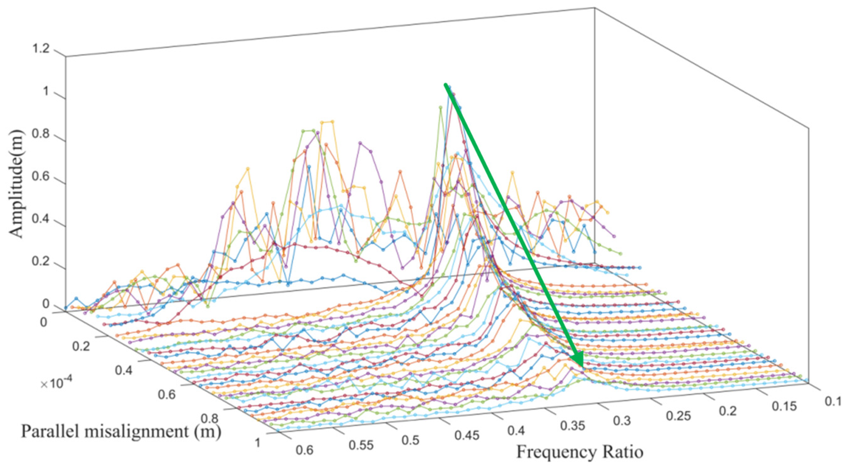
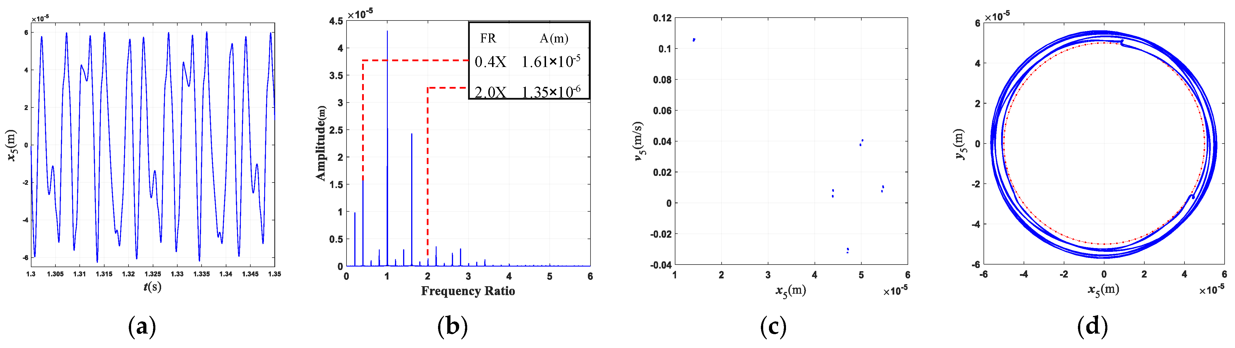
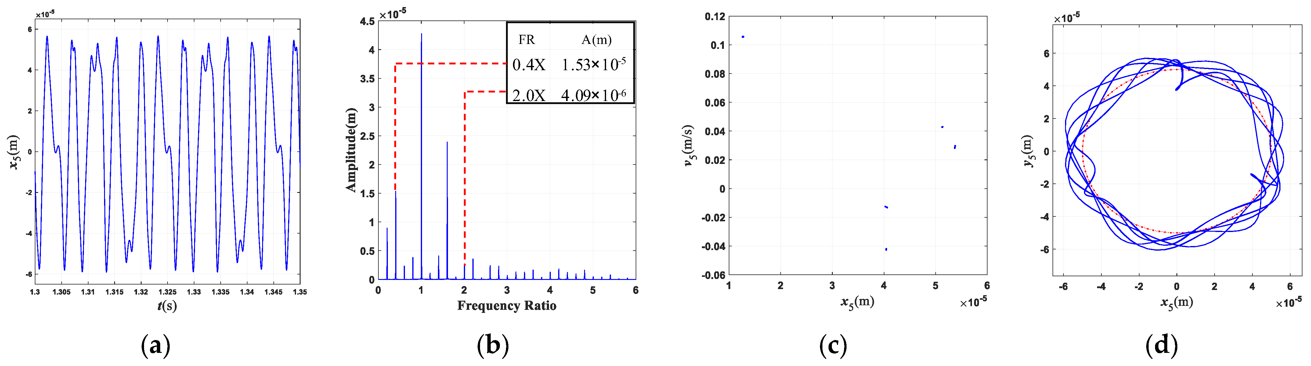
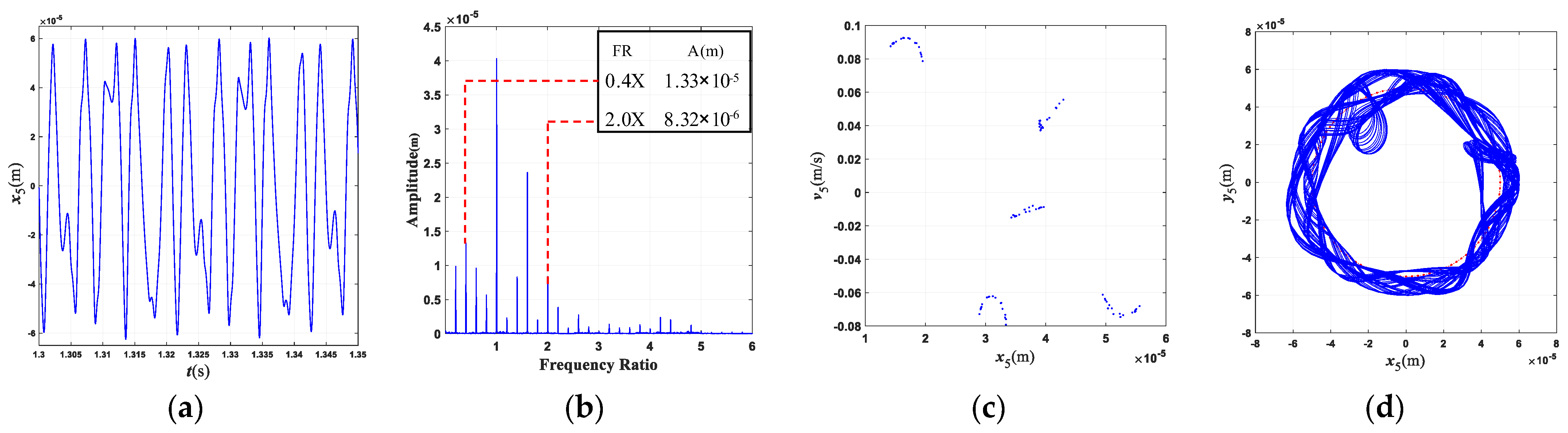
4.2.1. Parallel Misalignment
4.2.2. Angle Misalignment
4.3. Influence of Rub-Collision Parameters
4.3.1. Rub-Collision Stiffness
4.3.2. Friction Coefficient
4.4. Influence of Wall Thickness
5. Validation of Theoretical Modeling Approach
6. Conclusions
- (1)
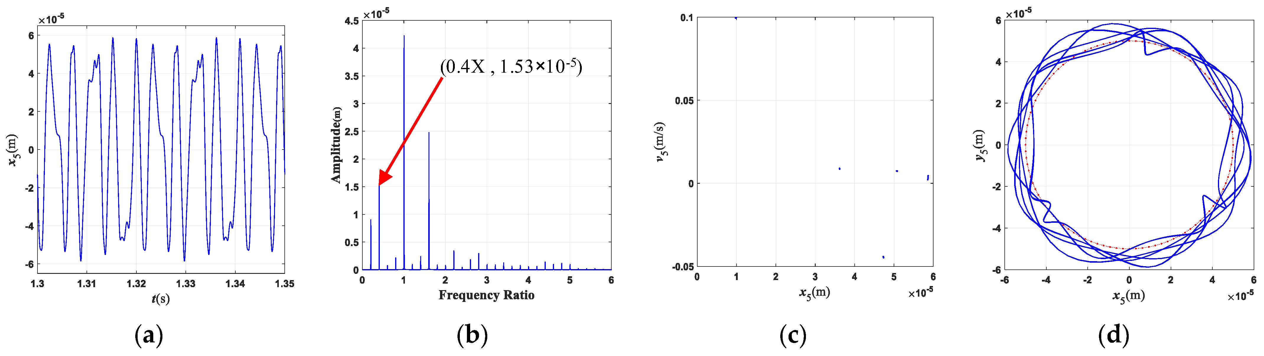
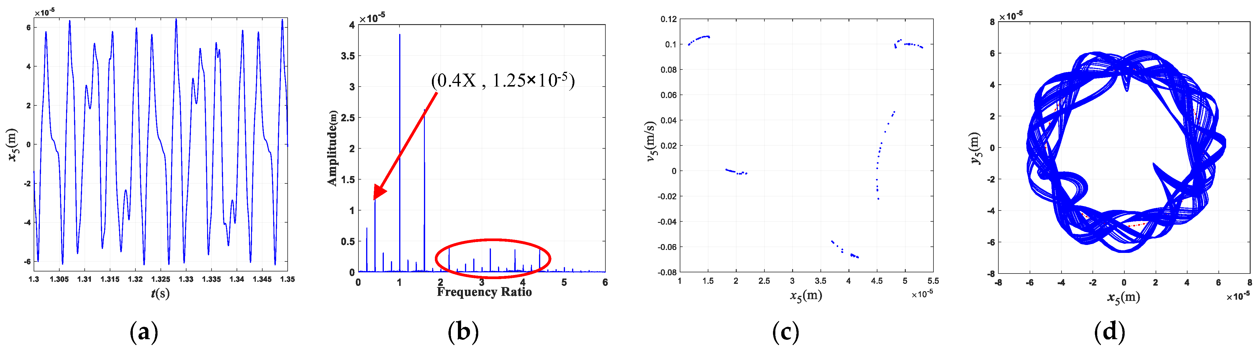
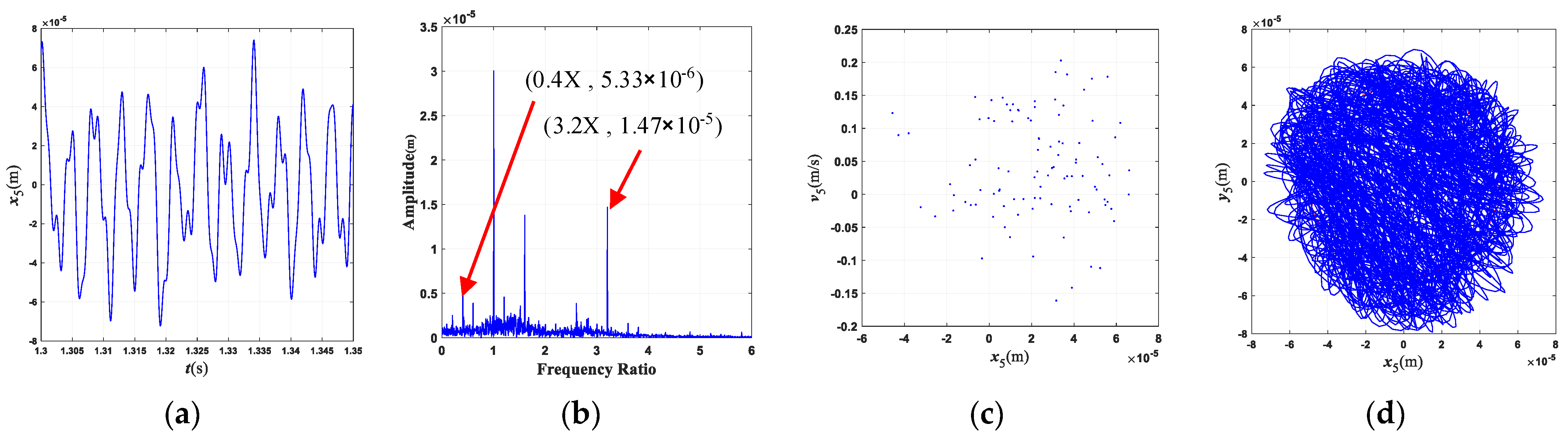
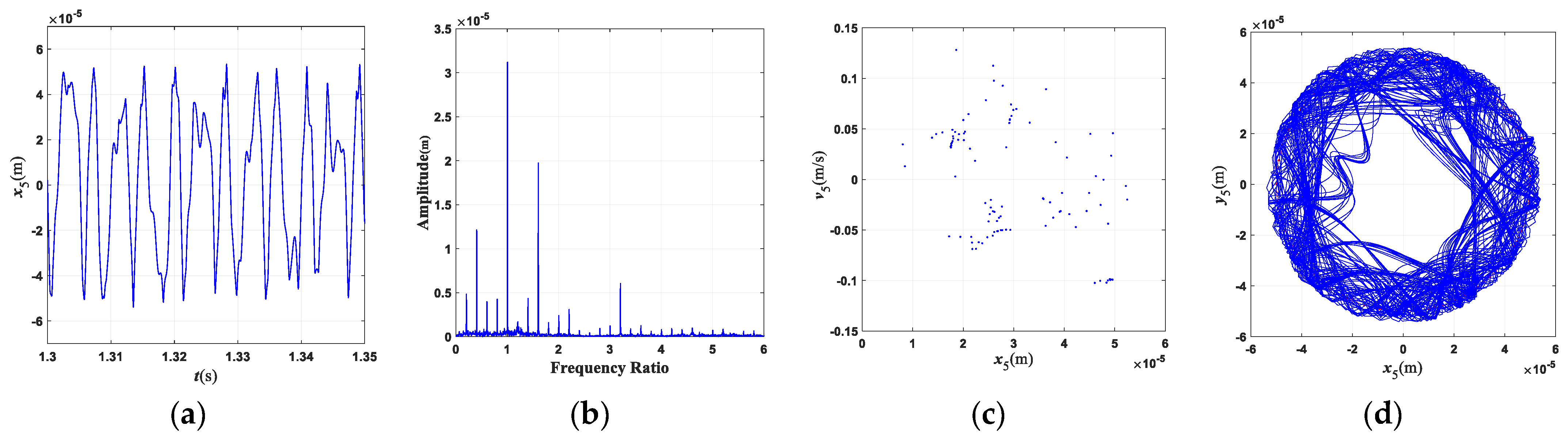
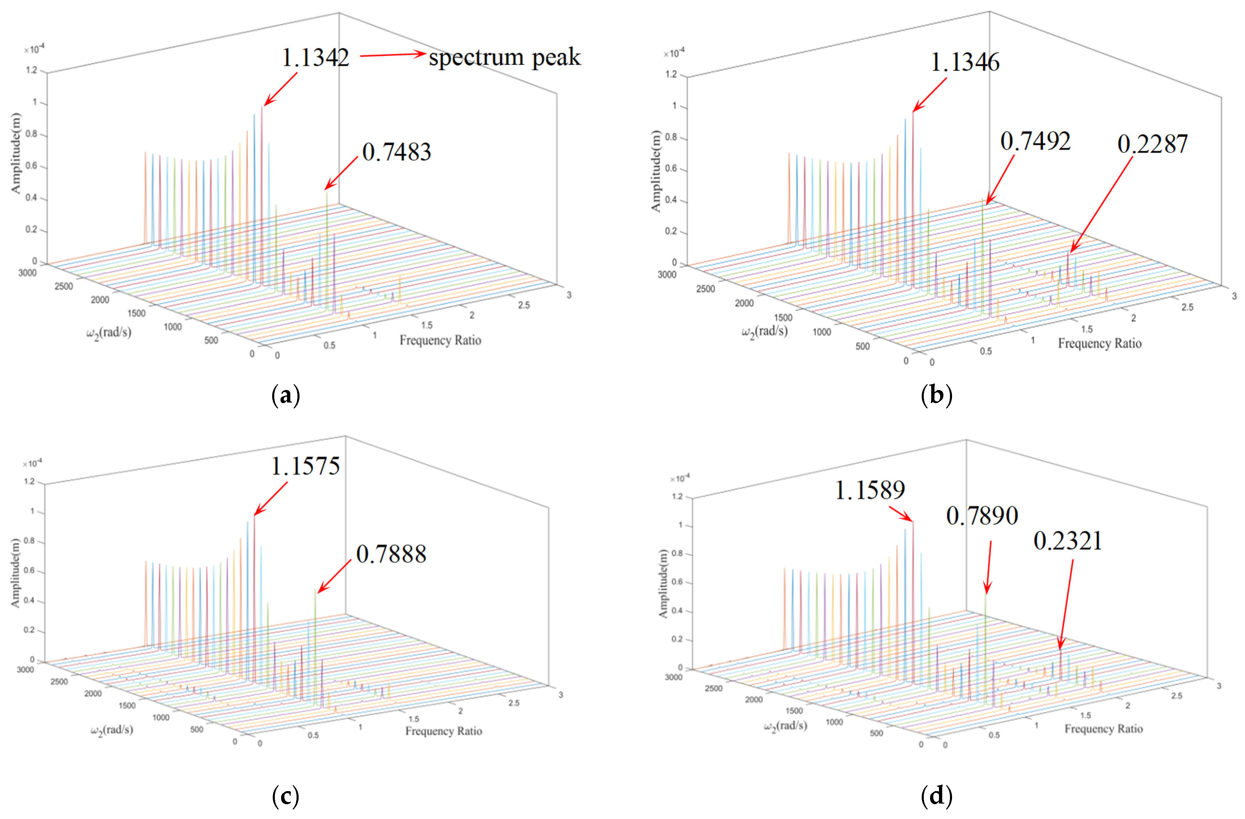
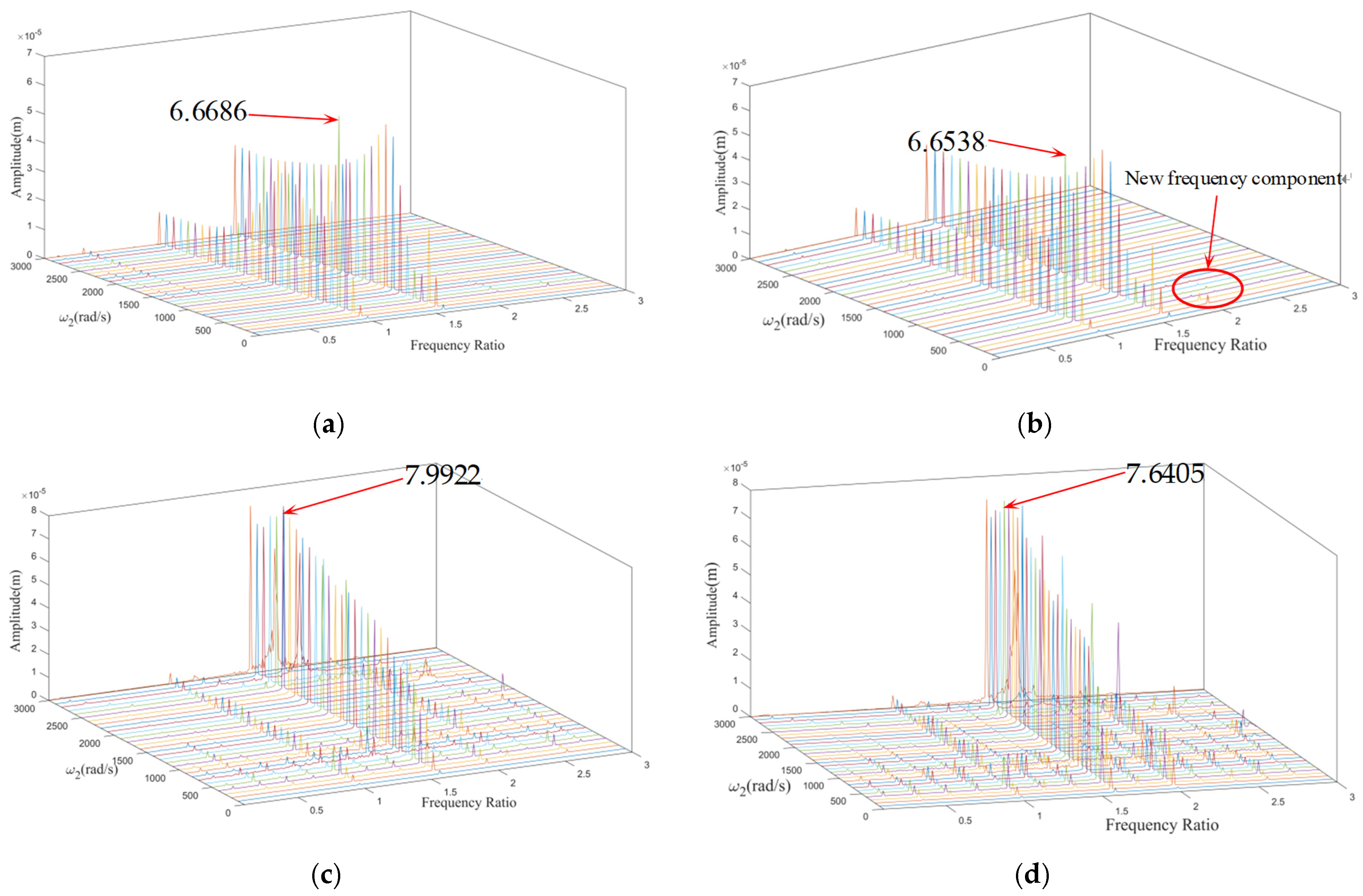
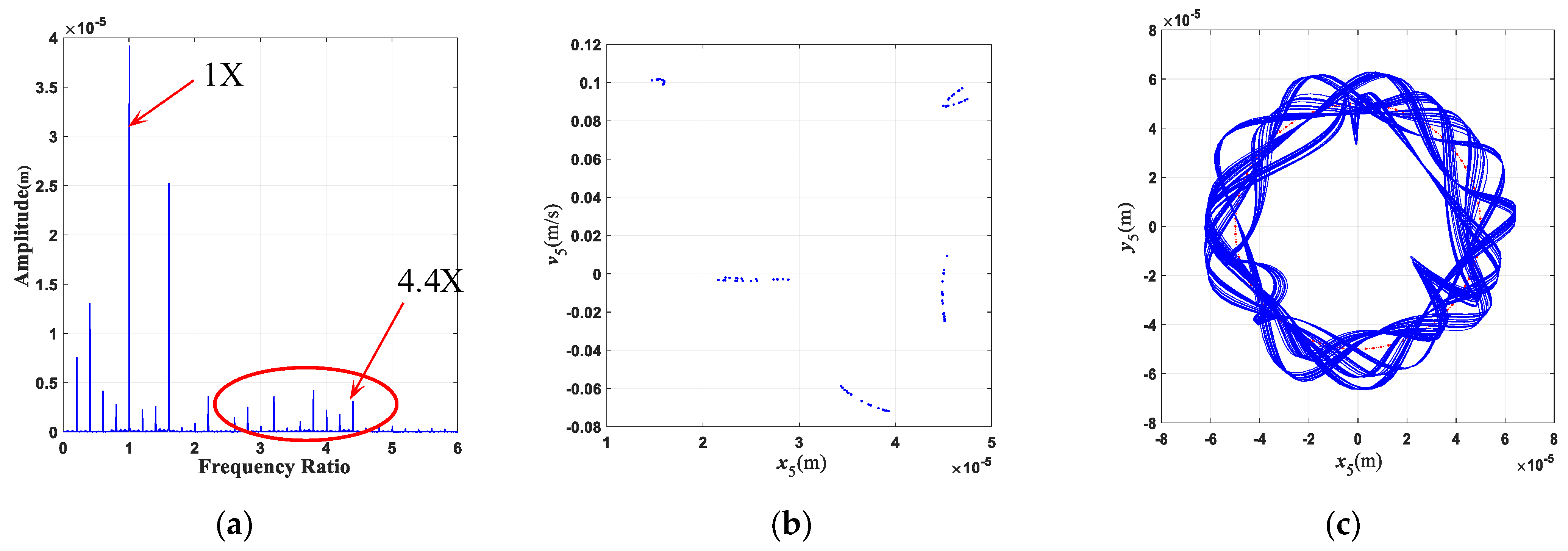
- The characteristic frequency of the misalignment fault for this three-rotor system is 2×; the characteristic frequency of the rub-collision fault is 0.4×, which is often accompanied by 0.6×, 2.2×, and other frequency components. The characteristic frequency of coupling faults mainly includes 2×, 0.4×, 0.6×, etc., and the frequency component is more complicated than that of a single fault.
- (2)
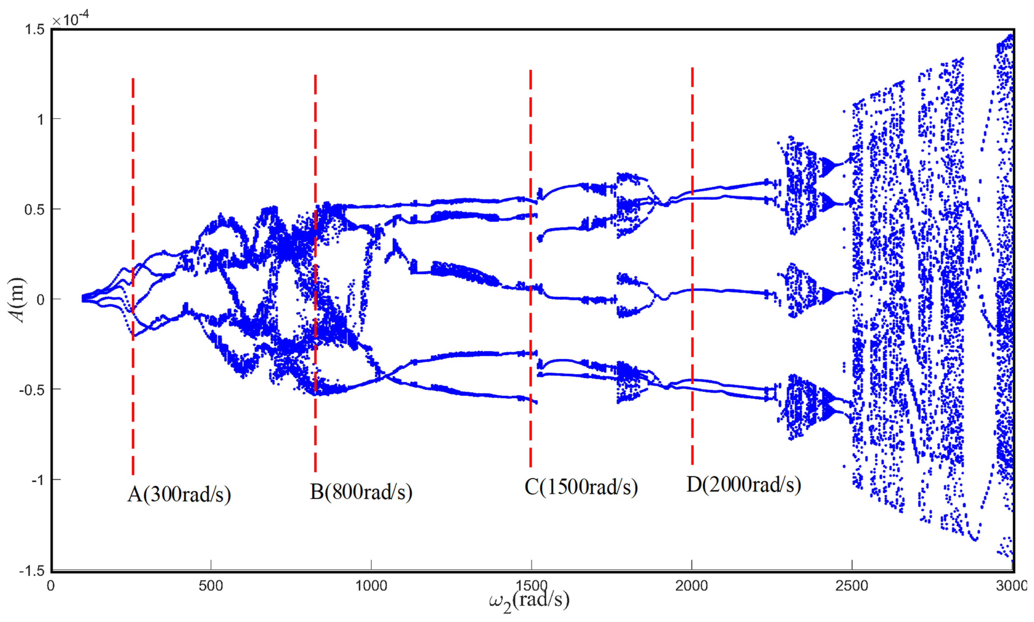
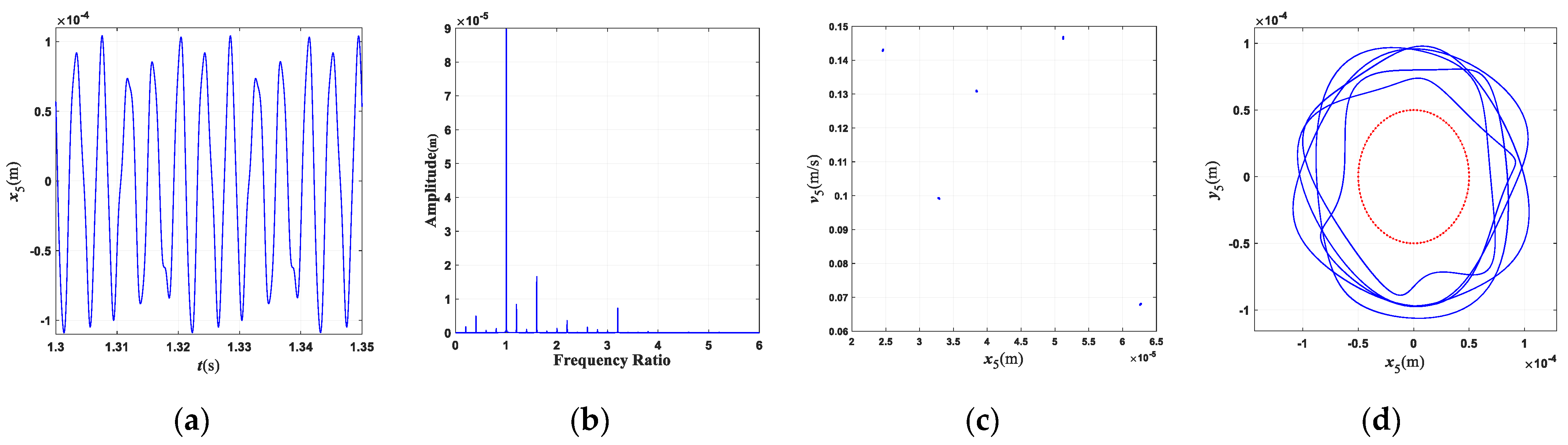
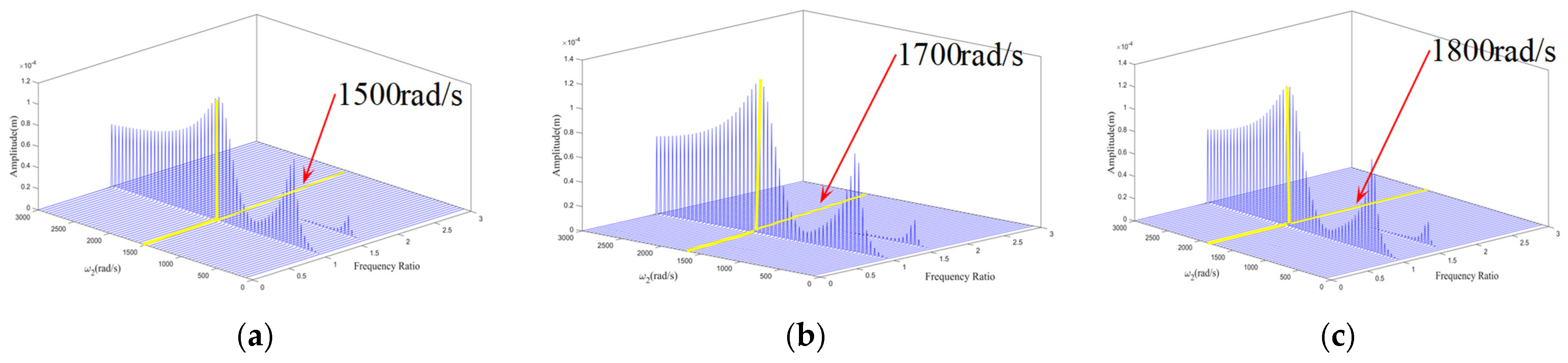
- The rotating speed and clutch misalignment have essential influence on the nonlinear behaviors of the three-rotor system. The system exhibits complex dynamical behaviors such as periodic, multi-periodic, quasi-periodic, and chaos with an increase in the rotating speed. With the increase in the parallel misalignment, the amplitude of 2× gradually increases, and the amplitude of 0.4× is relatively decreased; the parallel misalignment can inhibit rub-collision vibration to a certain extent; as the angle misalignment enlarges, the vibration displacement of the rotor enlarges, and the amplitude of high frequency such as 3.4× increases relatively; the enlargement of the angle misalignment does not change the amplitude of the misalignment feature frequency, which is mainly excited by the parallel misalignment.
- (3)
- The motion state of the system changes significantly, and the nonlinear characteristics gradually strengthen with the enlargement of the rubbing parameters. When the rub-collision rigidity increases, the vibration displacement of the LP turbine decreases, the amplitude for the characteristic frequency (0.4×) of rub-collision increases, and the amplitude for the characteristic frequency of rub-collision decreases. When the friction coefficient increases, the vibration displacement of the LP turbine remains essentially constant. As the wall thickness of the shaft increases, the second critical rotating speed increases, while the first critical rotating speed is almost unchanged.
Author Contributions
Funding
Data Availability Statement
Conflicts of Interest
References
- Fu, C.; Zhu, W.; Zheng, Z.; Sun, C.; Yang, Y.; Lu, K. Nonlinear responses of a dual-rotor system with rub-collision fault subject to interval uncertain parameters. Mech. Syst. Signal. Process. 2022, 170, 108827. [Google Scholar] [CrossRef]
- Pan, W.; Li, X.; Ling, L.; Qu, H. Dynamic modeling and response analysis of rub-collision rotor system with squeeze film damper under maneuvering load. Appl. Math. Model 2023, 114, 544–582. [Google Scholar] [CrossRef]
- Zhao, J.; Xing, L.; Ma, X.; Wang, Y.; Gao, D.; Du, G. Impact-Rubbings Dynamics Behavior of Magnetic-Liquid Double Suspension Bearing in Electromagnetic Failure Model. Appl. Sci. 2021, 11, 6345. [Google Scholar] [CrossRef]
- Song, X.; Ren, Y.; Han, Q. Nonlinear vibration of rotating cylindrical shell due to unilateral contact induced tip rubbing impact: Theoretical and experimental verification. Mech. Syst. Signal. Process. 2022, 164, 108244. [Google Scholar] [CrossRef]
- Zhang, X.; Yang, Y.; Ma, H.; Shi, M.; Wang, P. A novel diagnosis indicator for rub-collision of rotor system via energy method. Mech. Syst. Signal. Process. 2023, 185, 109825. [Google Scholar] [CrossRef]
- Xu, M.; Zhang, H.; Miao, H.; Hao, J.; Li, C.; Song, W.; Yao, G.; Zhang, Y. Model-based vibration response analysis and experimental verification of lathe spindle-housing-belt system with rubbing. Mech. Syst. Signal. Process. 2023, 186, 109841. [Google Scholar] [CrossRef]
- Hou, Y.; Cao, S.; Kang, Y. Study on the frequency modulation phenomenon in the rotor system with blade-casing rub-impact fault. Int. J. Nonlin. Mech. 2024, 159, 104626. [Google Scholar] [CrossRef]
- Jin, Y.; Liu, Z.; Yang, Y.; Li, F.; Chen, Y. Nonlinear vibrations of a dual-rotor-bearing-coupling misalignment system with blade-casing rubbing. J. Sound Vib. 2021, 497, 115948. [Google Scholar] [CrossRef]
- Li, Y.; Zhang, J.; Wang, L.; Chen, Y. A fault feature extraction method for rotor rubbing based on load identification and measured impact response. Procedia Eng. 2011, 24, 793–797. [Google Scholar]
- Wang, N.; Jiang, D. Vibration response characteristics of a dual-rotor with unbalance-misalignment coupling faults: Theoretical analysis and experimental study. Mech. Mach. Theory 2018, 125, 207–219. [Google Scholar] [CrossRef]
- Huang, W.; Tian, H.; Ma, H.; Wang, P.; Yang, Y.; Han, Q. An improved method for calculating the lateral and angular stiffness of spline couplings considering parallel misalignment. Mech. Mach. Theory 2023, 189, 105436. [Google Scholar] [CrossRef]
- Tiwari, R.; Kumar, P. An innovative virtual trial misalignment approach for identification of unbalance, sensor and active magnetic bearing misalignment along with its stiffness parameters in a magnetically levitated flexible rotor system. Mech. Syst. Signal. Process. 2022, 167, 108540. [Google Scholar] [CrossRef]
- Shinde, P.V.; Desavale, R.G. Application of dimension analysis and soft competitive tool to predict compound faults present in rotor-bearing systems. Measurement 2022, 193, 110984. [Google Scholar] [CrossRef]
- Zhang, C.; Cao, P.; Zhu, R.; Chen, W.; Wang, D. Dynamic modeling and analysis of the spline joint-flexible coupling-rotor system with misalignment. J. Sound Vib. 2023, 554, 117696. [Google Scholar] [CrossRef]
- Zhao, Y.; Wang, H.; Lin, J.; Han, Q.; Liu, Y. Effect of internal excitation induced by non-uniform contact of roller bearings on nonlinear vibration and stability of rotor system under combined loads. Commun. Nonlinear Sci. 2023, 125, 107381. [Google Scholar] [CrossRef]
- Tang, H.; Ren, Y.; Xiang, J.; Kumar, A. Numerical and experimental analysis of rotor-bearing system for axial piston pump with misalignment–rubbing coupling fault. J. Sound Vib. 2023, 559, 117786. [Google Scholar] [CrossRef]
- Xu, H.; Yang, Y.; Ma, H.; Luo, Z.; Li, X.; Han, Q.; Wen, B. Vibration characteristics of bearing-rotor systems with inner ring dynamic misalignment. Int. J. Mech. Sci. 2022, 230, 107536. [Google Scholar] [CrossRef]
- Wang, P.; Yang, Y.; Ma, H.; Xu, H.; Li, X.; Luo, Z.; Wen, B. Vibration characteristics of rotor-bearing system with angular misalignment and cage fracture: Simulation and experiment. Mech. Syst. Signal. Process. 2023, 182, 109545. [Google Scholar] [CrossRef]
- Wu, K.; Liu, Z.; Ding, Q.; Shackleton, P.; Cattley, R.; Gu, F.; Ball, A.D. Vibration responses of rotor systems in diesel multiple units under dynamic spatial misalignments and base motions. J. Sound Vib. 2021, 492, 115817. [Google Scholar] [CrossRef]
- da Silva Tuckmantel, F.W.; Cavalca, K.L. Vibration signatures of a rotor-coupling-bearing system under angular misalignment. Mech. Mach. Theory 2019, 133, 559–583. [Google Scholar] [CrossRef]
- Lees, A.W. Misalignment in rigidly coupled rotors. J. Sound Vib. 2007, 305, 261–271. [Google Scholar] [CrossRef]
- Fu, X.Q.; Jia, W.T.; Xu, H.; Song, S.L. Imbalance–misalignment–rubbing coupling faults in hydraulic turbine vibration. Optik 2016, 127, 3708–3712. [Google Scholar] [CrossRef]
- Lu, K.; Cheng, H.; Zhang, W.; Zhang, H.; Zhang, K.; Fu, C. Nonlinear dynamic behavior of a dual-rotor bearing system with coupling misalignment and rubbing faults. Meas. Sci. Technol. 2022, 34, 014005. [Google Scholar]
- Jin, Y.; Hou, L.; Chen, Y.; Lu, Z. An effective crack position diagnosis method for the hollow shaft rotor system based on the convolutional neural network and deep metric learning. Chin. J. Aeronaut. 2022, 35, 242–254. [Google Scholar] [CrossRef]
- Han, Z.; Wang, D.; Wang, Y.; Hong, J.; Cheng, R. Dynamic effects of the initial skewness of the inertial principal axis on the rotor with bolted joint. Mech. Syst. Signal. Process. 2023, 200, 110564. [Google Scholar] [CrossRef]
- Chen, Y.; Hou, L.; Chen, G.; Song, H.; Lin, R.; Jin, Y.; Chen, Y. Nonlinear dynamics analysis of a dual-rotor-bearing-casing system based on a modified HB-AFT method. Mech. Syst. Signal. Process. 2023, 185, 109805. [Google Scholar] [CrossRef]
- Fan, S.; Hong, L.; Jiang, J. Blue-Sky Catastrophic Bifurcations Behind Emergence and Disappearance of Quasiperiodic Rubbing Oscillations in a Piecewise Smooth Rotor–Stator System. Int. J. Bifurcat. Chaos 2022, 32, 2250221. [Google Scholar] [CrossRef]
- Lu, K.; Jin, Y.; Huang, P.; Zhang, F.; Zhang, H.; Fu, C.; Chen, Y. The applications of POD method in dual rotor-bearing systems with coupling misalignment. Mech. Syst. Signal. Process. 2021, 150, 107236. [Google Scholar] [CrossRef]
- Li, Q.; Zhang, W.; Chen, F.; Huang, G.; Wang, X.; Yuan, W.; Xiong, X. Fault diagnosis of nuclear power plant sliding bearing-rotor systems using deep convolutional generative adversarial networks. Nucl. Eng. Technol. 2024. [Google Scholar] [CrossRef]
- Xiang, L.; Zhang, X.; Zhang, Y.; Hu, A.; Bing, H. A novel method for rotor fault diagnosis based on deep transfer learning with simulated samples. Measurement 2023, 207, 112350. [Google Scholar] [CrossRef]


| Parameters | Values | Parameters | Values |
|---|---|---|---|
| Lumped mass m1 (kg) | 1.5 | Length of l1 (m) | 0.3 |
| Lumped mass m2 (kg) | 6 | Length of l2 (m) | 0.3 |
| Lumped mass m3 (kg) | 10 | Length of l3 (m) | 0.8 |
| Lumped mass m4 (kg) | 2 | Length of l4 (m) | 0.2 |
| Lumped mass m5 (kg) | 6 | Length of l5 (m) | 0.2 |
| Lumped mass m6 (kg) | 1.5 | Length of l6 (m) | 0.3 |
| Lumped mass mh (kg) | 8 | Length of l7 (m) | 0.3 |
| Support stiffness k1 of bearing 1 (N/m) | 3 106 | Damping coefficient c12 of flexible shaft segment (N·s/m) | 800 |
| Support stiffness k2 of bearing 2 (N/m) | 3 106 | Damping coefficient c23 of flexible shaft segment (N·s/m) | 800 |
| Support stiffness k3 of bearing 3 (N/m) | 3 106 | Damping coefficient c34 of flexible shaft segment (N·s/m) | 800 |
| Support stiffness k4 of bearing 4 (N/m) | 3 106 | Damping coefficient c45 of flexible shaft segment (N·s/m) | 800 |
| Support stiffness k5 of bearing 5 (N/m) | 3 106 | Damping coefficient c56 of flexible shaft segment (N·s/m) | 800 |
| Support damping coefficient c1 of bearing 1 (N·s/m) | 1200 | Polar moment of inertia Jp (kg·m2) | 0.04 |
| Support damping coefficient c2 of bearing 2 (N·s/m) | 1200 | Diameter moment of inertia Jd (kg·m2) | 0.02 |
| Support damping coefficient c3 of bearing 3 (N·s/m) | 1200 | The flexible modulus E of the shaft (kg·m2) | 2 1011 |
| Support damping coefficient c4 of bearing 4 (N·s/m) | 1200 | Inner-ring radius r (m) | 40.1 10−3 |
| Support damping coefficient c5 of bearing 5 (N·s/m) | 1200 | Outer-ring radius R (m) | 63.9 10−3 |
| Mass eccentricity e1 of LP compressor disk (m) | 5 10−5 | Rolling element number Nb | 8 |
| Mass eccentricity e2 of LP turbine disk (m) | 5 10−5 | Stiffness Kb of inter-shaft bearing (N/m) | 13.34 109 |
| Mass eccentricity eh of HP rotor disk (m) | 3 10−5 | Clearance of inter-shaft bearing (m) | 5 10−6 |
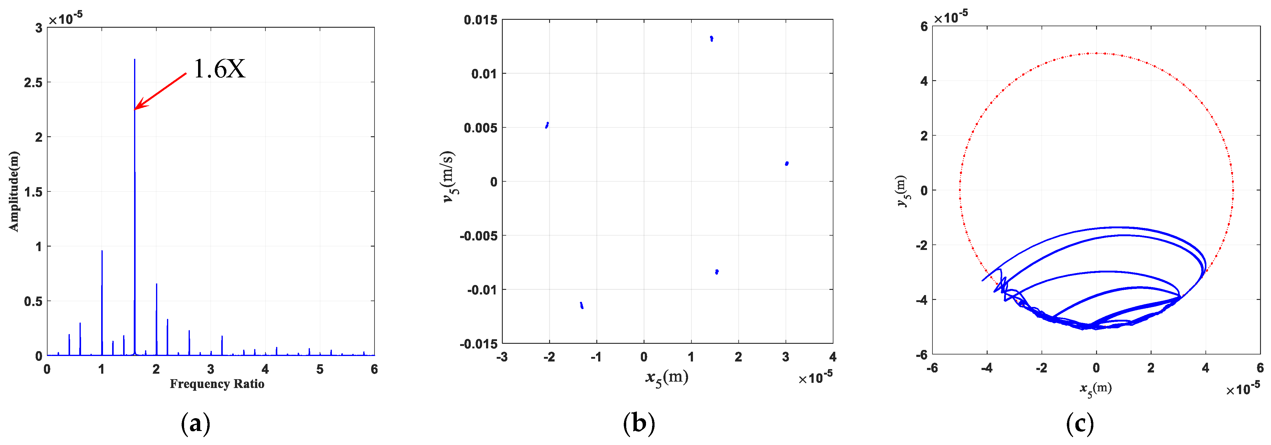
| The rotational speed ratio of HP and LP rotors | 1.6 | Outer diameter D of the LP shaft (m) | 3.936 10−2 |
Disclaimer/Publisher’s Note: The statements, opinions and data contained in all publications are solely those of the individual author(s) and contributor(s) and not of MDPI and/or the editor(s). MDPI and/or the editor(s) disclaim responsibility for any injury to people or property resulting from any ideas, methods, instructions or products referred to in the content. |
© 2024 by the authors. Licensee MDPI, Basel, Switzerland. This article is an open access article distributed under the terms and conditions of the Creative Commons Attribution (CC BY) license (https://creativecommons.org/licenses/by/4.0/).
Share and Cite
Nan, G.; Wang, H.; Yu, D. Dynamic Analysis of Three-Rotor System with Hollow Shaft under Clutch Misalignment. Aerospace 2024, 11, 319. https://doi.org/10.3390/aerospace11040319
Nan G, Wang H, Yu D. Dynamic Analysis of Three-Rotor System with Hollow Shaft under Clutch Misalignment. Aerospace. 2024; 11(4):319. https://doi.org/10.3390/aerospace11040319
Chicago/Turabian StyleNan, Guofang, Haoyu Wang, and Dengliang Yu. 2024. "Dynamic Analysis of Three-Rotor System with Hollow Shaft under Clutch Misalignment" Aerospace 11, no. 4: 319. https://doi.org/10.3390/aerospace11040319
APA StyleNan, G., Wang, H., & Yu, D. (2024). Dynamic Analysis of Three-Rotor System with Hollow Shaft under Clutch Misalignment. Aerospace, 11(4), 319. https://doi.org/10.3390/aerospace11040319