Abstract
Morphing structures are a relatively new aircraft technology currently being investigated for a variety of applications, from civil to military. Despite the lack of literature maturity and its complexity, morphing wings offer significant aerodynamic benefits over a wide range of flight conditions, enabling reduced aircraft fuel consumption and airframe noise, longer range and higher efficiency. The aim of this study is to investigate the impact of morphing horizontal tail design on aircraft performance and flight mechanics. This study is conducted on a 1:5 scale model of a Preceptor N-3 Pup at its trim condition, of which the longitudinal dynamics is implemented in MATLAB release 2022. Starting from the original horizontal tail airfoil NACA 0012 with the elevator deflected at the trim value, this is modified by using the X-Foil tool to obtain a smooth morphing airfoil trailing edge shape with the same . By comparing both configurations and their influence on the whole aircraft, the resulting improvements are evaluated in terms of stability in the short-period mode, reduction in the parasitic drag coefficient , and increased endurance at various altitudes.
1. Introduction
Morphing wing design concerns an automated shape adaptation to produce smooth and continuous deformation of an aircraft’s fixed or movable lifting surfaces during flight in order to obtain optimal performance in multiple flight phases. A stricter definition of aircraft morphing is laid out by DARPA in its Morphing Aircraft Structures (MAS) project [1], aimed at flying UAVs with variable wings for military applications [2]. Morphing technology was referred to as the ability for an aircraft to perform the following:
- Change state substantially to adapt to changing missions and mission environments;
- Provide superior system capability not possible without reconfiguration;
- Integrate innovative combinations of advanced materials, actuators, flow controllers and mechanisms to achieve the required state change.
Morphing aircraft structures are a relatively new concept. For years, pioneer engineers have been inspired by the seamless shape-changing capabilities of bird wings, and have tried to mimic such a natural ability to realize aircraft wing shape optimization and control [3]. Variable camber concepts were explored since the 1980s to smoothly deform wing leading and trailing edges during different flight conditions [4].
Nowadays, morphing wing devices have become a contemporary concept in aeronautics research due to significant advances in materials, structures and control logics. The real breakthrough came from material technology with the introduction of SMAs (shape memory alloys). Some application of SMAs started in the 1970s, and, by the 1990s, the DARPA program Smart Wings [5] looked at the use of them as compact actuators for morphing wings. Between 2003 and 2007, DARPA launched the Morphing Aircraft Structures (MAS) program, which had as its objective the study of a UAV with variable wings for military applications. In 2011, Airbus launched the SARISTU program, which is probably the most major research ever carried out in Europe on adaptive structures. The program included the construction of a 5.5 m span wing section, equipped with three morphing wing devices, in turn realized by DLR, CIRA and EADS-IW. They developed a droop nose [6] aimed at increasing the take-off and landing performance, an adaptive trailing edge device [7] aimed at improving the aircraft performance in cruise and an innovative adaptive winglet [8] for gust alleviation, respectively. These devices were controlled by conventional actuation concepts enabling more mature and practical implementations. In 2015, the assembled wing underwent WT tests at TsAGI, the Russian Aeronautical Research Centre, where the three systems proved their capabilities in a relevant environment (TRL 6). A morphing aileron demonstrator [9] was designed and successfully tested in laboratory conditions to validate the actuation system’s authority and reliability.
In Clean Sky AIRGREEN2, a deformable leading edge morphing device and a multi-functional segmented flap system were considered [10] for the improvement of the aerodynamic performance of a turboprop regional aircraft wing in high-lift conditions. Furthermore, a fault-tolerant adaptive winglet with shape-changing capabilities was developed to enhance wing aerodynamic efficiency () in off-design conditions and reduce maneuver loads on a regional turboprop aircraft. The integrated design of the adaptive winglet is detailed in [11].
Morphing wings are an interesting subject to study for different reasons. First of all, the enormous charm of such a technology, which is very innovative and still little studied and implemented. Morphing wing devices have proven to show great potential to obtain augmented aerodynamic efficiency in every flight phase, thus remaining a very attractive factor to reduce fuel consumption and/or to increase endurance. Morphing-wing research for UAVs and micro aircraft (MAVs) is also growing in significance. This interest is mainly driven by the increased chance to mimic bats and insects; of the former, we want to imitate the structure of the wing that branches out over the entire surface in order to create very light devices; of the latter, we are interested in the possibility of creating multi-wing aircraft [12]. Besides, morphing wings are suitable to effectively achieve gust alleviation during flight [13].
Morphing-wing research for UAVs and micro aircraft (MAVs) is also growing in significance [14,15].
However, the majority of the studies carried out so far on morphing wing devices deals with structural and material issues mainly, along with aerodynamic performance [16,17]. From the point of view of flight dynamics, there is a substantial difference whether the geometry variation due to morphing aims to achieve maximum performance in the various flight phases or to replace the traditional surfaces for controlling the aircraft. Numerous dynamic approaches with different levels of complexity and computational efficiency can be found in the literature [18]. The choice of the most suitable model is made while considering many variables. Regarding the computational efficiency, the CPU time represents a qualitative evaluation of the time required for the non-linear simulation based on each method; rapid and continuous wing morphing refer, respectively, to the ability of the method to model rapid geometry changes and large-scale continuum deformations; the actuator model specifies how the morphing variables are handled; the label linearized system characterizes the system after linearization at a trim point as linear time-invariant (LTI) or linear time-varying (LTV); finally, the number of ODEs is a measure of the size of the system of differential equations required for non-linear simulation, with n being the number of bodies of which the system is comprised [12,19].
The aim of present work is to study the impact of the horizontal tail morphing application on the longitudinal dynamics of a reference aircraft, by analyzing the achieved results in terms of stability and transient characteristics of the phugoid and short-period modes, along with the basic performance of the aircraft. This study is a preliminary assessment in which only the trim condition is considered to compare the basic aircraft with that equipped with a morphing horizontal surface.
The present study is conducted on a 1:5 scale model of a Preceptor N-3 Pup by implementing its longitudinal dynamics in the MATLAB environment. The XFOIL program [20] is used to obtain the polars of the airfoils analyzed and to model the morphing airfoil. Finally, the Matlab software is used again to analyze the performance of the aircraft by plotting the power-required curves and comparing the results of the basic aircraft with those of the morphing one.
2. Mathematical Model
An accurate non-linear mathematical model of the aircraft constitutes the basis of the present work. The classical rigid body equations of the motion in the body axes have been used [21].
where:
Into (2) as follows:
Into (3) aerodynamic coefficients are expressed by the following:
Mathematical model has been applied to an UAS studied in previous works [22]. It is a scaled model (1:5) of ultra-light aircraft Perceptor N3-PUP.
Equation (5), already used in cited previous studies, has been used to model the aircraft polar as follows:
Table 1 shows the geometric characteristics of the studied aircraft.

Table 1.
UAS geometric characteristics.
3. Study of Actual Horizontal Tail
The horizontal tail consists of a NACA 0012 airfoil and features a hinged elevator at of the mean chord (Figure 1).
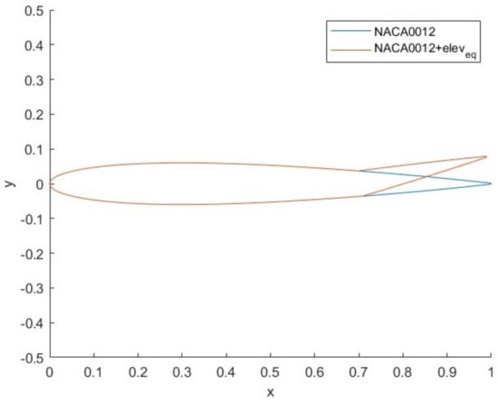
Figure 1.
Tail airfoil without (blue) and with (red) elevator deflection.
In order to study the airfoil morphing in the horizontal tail and then compare the original aircraft with the morphed one, it is necessary to define a trim condition. As this is a preliminary feasibility study to analyze the merits of morphing technologies, it will only deal with the equilibrium condition of the aircraft. The weight and lift coefficients at equilibrium have already been obtained in the previous paper [22], defined the equilibrium speed in steady rectilinear flight equal to 24.6305 m/s at sea level ( = 313,000). The following system of trim equations is then set up in order to derive the angle of attack and deflection of the elevator.
Calculated the deflection angle of the elevator at trim condition, its aerodynamic characteristics are analyzed by plotting the polars obtained through the XFOIL release 6.99 software.
The polars of the NACA 0012 airfoil and the modified NACA 0012 with elevator deflection of −12 deg are shown in Figure 2 and Figure 3, Table 2 shows the aerodynamic coefficients of both airfoils.
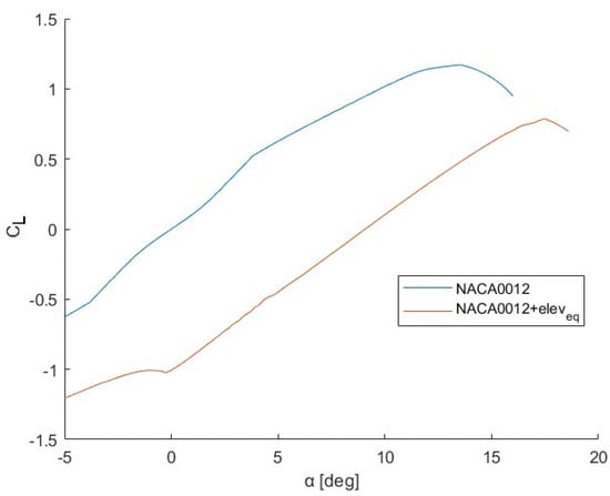
Figure 2.
vs. curve for airfoil with (red) or without (blue) elevator deflection.
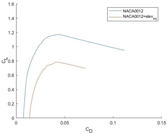
Figure 3.
vs. curve for airfoil with (red) or without (blue) elevator deflection.

Table 2.
Aerodynamic parameters.
4. Study of Morphing Horizontal Tail
To reach the research object, the morphing airfoil should exactly replicate the effect of the elevator with trim deflection. The first condition to be respected is that the airfoil in question must have the same value as the NACA 0012 with the elevator at −12°, so for the same angle of attack it must produce the same lift as the airfoil with elevator.
This way, we can evaluate the tail morphing influence on aircraft dynamics without considering other parameters, such as angle of attack or speed variations.
Furthermore, for the two curves to overlap perfectly, a certain tail incidence angle must be considered for the morphing airfoil.
As already mentioned, the morphing technology considered is the morphing of the airfoil camber during the flight.
For the preliminary study in the trim condition, we will look for the camber value and the maximum camber point along the mean chord that the airfoil must replicate for the effect of the deflected elevator at equilibrium. To do this, an experimental function can be found that binds the and the camber of the airfoil; in this way, starting from the of NACA 0012 with , it will be possible to calculate the camber value of the morphing airfoil.
Three points of maximum camber along the HT mean chord (c) were considered, namely, at 0.4c, 0.5c and 0.6c. Using the XFOIL software, the polar of the airfoils with thickness t equal to 0.12c and camber from −0.04c to 0.04c for the three maximum camber points were obtained. Subsequently, the values for each camber were calculated for the three and, plotting the results, the three curves shown in Figure 4, Figure 5 and Figure 6 were extracted.
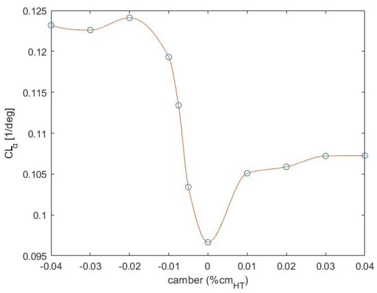
Figure 4.
Variation of with camber at = 0.4.
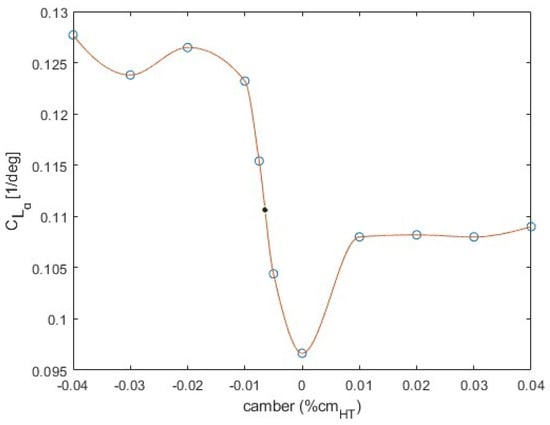
Figure 5.
Variation of with camber at = 0.5.
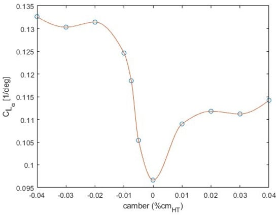
Figure 6.
Variation of with camber at = 0.6.
The trend has been transposed in a polynomial through polyfit techniques. To improve the precision of the function, a value of n equal to 12 has been chosen, so the coefficients of the polynomial p for each of the three curves will be 12 + 1. The form of the polynomial equation is reported below.
Consequently, the functions of the three curves, which link the with the camber c at the same , can be written.
By replacing the value of NACA 0012 with in the equations, the corresponding camber values are obtained for the three maximum camber points. Obtained results are reported in Table 3.

Table 3.
Camber VS Max camber point.
In Figure 7, vs. curves for NACA 0012 (blue), NACA 0012 with elevator trim deflection (red), morphed airfoil with maximum camber at 0.4c (yellow), ate 0.5c (violet) and 0.6c (green) are shown. The obtained results for morphed airfoils are much more similar to original profile than the one with elevator deflection. To reach the object of our valuation, it is necessary to consider a tail incidence angle to ensure that the morphing profiles perfectly replicate the lift contribution of the profile with elevator.
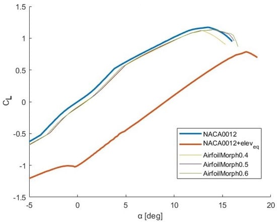
Figure 7.
vs. curve of NACA 0012, NACA 0012 + and the three morphing airfoils.
A tail incidence angle equal to −8.35 deg was calculated, and, by applying this modification to the airfoils, the polars were obtained.
Now, as shown in Figure 8, the vs. curves of NACA 0012 with and of the three morphing profiles overlap.
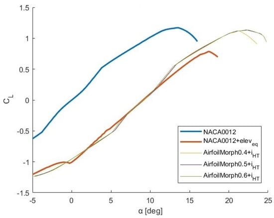
Figure 8.
vs. curve of NACA 0012, NACA 0012 + and the three morphing airfoils with .
The first important obtained result (Figure 9) is that, even if the slope of the curve is the same, morphing profiles allow to reach to higher for the same value of respect to profile with elevator. Their results are comparable with NACA 0012 airfoil without mobile surface.
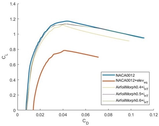
Figure 9.
vs. curve of NACA 0012, NACA 0012 + and the three morphing airfoils with .
It is specified that, although in the graph the curves do not coincide perfectly, they have the same value and that their not perfectly straight trend is due to the fact that they have been obtained through experimental data.
Besides, as it is possible to note by Figure 10, the same drag coefficient has been obtained for the higher values of the angle of attack.
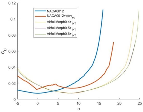
Figure 10.
vs. curve of NACA 0012, NACA 0012 + and the three morphing airfoils with .
In Figure 11, the aerodynamic efficiency’s (E) trend, as the variation, is reported. It shows how morphing airfoil characteristics are much more compliant with the NACA 0012 airfoil than the airfoil with elevator.
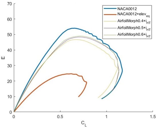
Figure 11.
E vs. curve of NACA 0012, NACA 0012+ and the three morphing airfoils with .
The trends in the aerodynamic coefficients and a summary table (Table 4) of the main characteristics are shown in order to be able to face a reasoned choice.

Table 4.
Aerodynamic main characteristics.
Even just from the analysis of the morphing profiles it is possible to notice a notable improvement compared to the NACA 0012 with ; from Figure 10 and Figure 11, it can be seen that the value of , and of drag in general, is greatly reduced, this means that for the same angle of incidence, the morphing airfoils are able to produce the same lift as the airfoil with elevator deflection but with much less drag production.
Furthermore, there is a great improvement in the values of , the key index for the evaluation of range and which will be discussed in detail later. In light of the above and taking into account the values shown in the table, it was decided to choose the morphing airfoil with camber equal to −0.00673 at as it is the right compromise between the improvement in and in the other aerodynamic coefficients.
Figure 12 shows the NACA 0012 airfoil with and the chosen morphing airfoil:
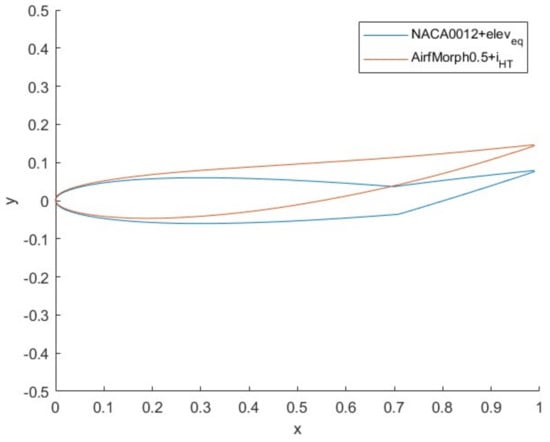
Figure 12.
NACA 0012 + and morphing airfoil.
5. Study of Longitudinal Dynamic of the Morphing Tail Aircraft
In the longitudinal dynamics of the aircraft, the horizontal tail plays a central role, as many stability derivatives depend on it, in particular, on its value. The parameters that are influenced by are shown below, making this dependence explicit.
It was considered that the distance between the aerodynamic center of the horizontal tail and that of the wing remains constant because the displacement of the aerodynamic center of the HT caused by the airfoil morphing is negligible and, moreover, being a model in the scale of 1:5, the distances are so small that a small variation would be inconsistent.
To take into account the morphing, it is considered that, compared to the basic aircraft, the horizontal tail is now made up of the morphing airfoil chosen; that is, the airfoil with a camber equal to −0.00673 at an of 0.5 and with a thickness t of 0.12 . Therefore, the of this airfoil will have to be considered to obtain the new .
To calculate starting from airfoil one, the following relationship have been considered:
The obtained stability derivatives are reported in Table 5.

Table 5.
Aerodynamic main characteristics.
In regards to the control derivatives and , since the deflection of the elevator has been replaced with the morphing airfoil, they will be equal to the following:
Basically, the lift contribution of the elevator given by times the elevator deflection has been replaced by of HT with the morphing airfoil times the tail incidence angle. Same thing regarding as follows:
After calculating the stability derivatives modified due to the morphing of the horizontal tail, the new dynamic matrix is written and the new eigenvalues are obtained as follows:
From the longitudinal dynamic analysis of the morphing aircraft, it emerges that its short-period mode is more stable than that of the initial configuration since the stability derivatives on which its damping depends; that is, , and , have been modified by morphing. This is an important result as the short-period is the mode that involves the greatest stresses on the aircraft and must necessarily be stable since, having a high frequency, it could not be controlled. In regards to the phugoid mode, this is not substantially modified like the short-period mode, as its damping depends on stability derivatives that have nothing to do with the influence of the horizontal tail on the aircraft. So, the modification obtained through airfoil morphing technology makes the short-period mode more stable, leaving the phugoid mode more or less unchanged. The following Table 6 and Table 7 show the variations in the transient characteristics of the longitudinal proper modes of the morphing aircraft with respect to the basic one.

Table 6.
Short-period mode characteristics.

Table 7.
Phugoid mode characteristics.
6. Effects of Morphing on Aircraft Performance: Power Required Curves Analysis
The aim of the present and other studies is to study technological innovations for surveillance unmanned, so the goal is to maximize its endurance. We will then look for the condition for which is maximized, this condition corresponds to the maximum endurance. The power required curves of the aircraft with the deflected elevator by the trim and with the morphing airfoil in the HT are plotted at zero altitude, reporting in the curves the point of the minimum power required (); that is, the one corresponding to the maximum and, therefore, to the maximum endurance.
Analyzing Figure 13 and Figure 14, it can be seen that the minimum of the curve is at a lower required power value and at a lower velocity for the morphing aircraft than that of the basic aircraft. That is to say, the basic aircraft can certainly fly at their speed of minimum power to maximize endurance, but with the morphing aircraft a higher maximum endurance value is obtained, as its is lower and the is higher. This means that, through morphing technology, at the same altitude, the aircraft is able to fly in trim by spending less energy and, consequently, there is an increase in terms of endurance.
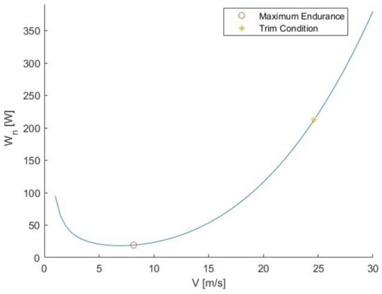
Figure 13.
Aircraft power required curves (HT with NACA 0012+) at z = 0.
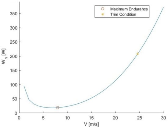
Figure 14.
Aircraft power required curves (HT with morphing airfoil) at z = 0.
The improvement in varying is shown in Figure 15.
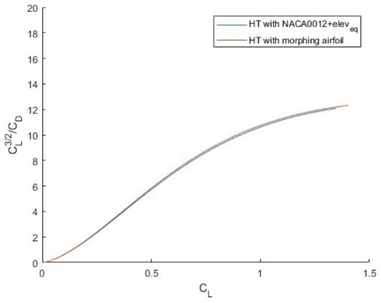
Figure 15.
vs. for aircraft equipped with standard tail and with morphing tail.
In Table 8, it is reported that the percentage of endurance increase at each considered altitude.

Table 8.
Improvement in and endurance due to morphing.
The improvement in the aerodynamic efficiency (E) with the variation in is shown in Figure 16. As it is easy to note, the efficiency of the aircraft equipped with a morphing tail is much more than the E of the traditional tail one. The mean improvement is about .
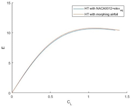
Figure 16.
E vs. for aircraft equipped with standard tail and with a morphing tail.
A range of different altitudes has then been considered (from 0 to 2500 m); above this altitude range, the ambient temperature decreases to values below the optimal operating temperature range of the model battery. Figure 17 and Figure 18 show the power required curves for classical aircraft and morphing aircraft at the following various considered altitudes:
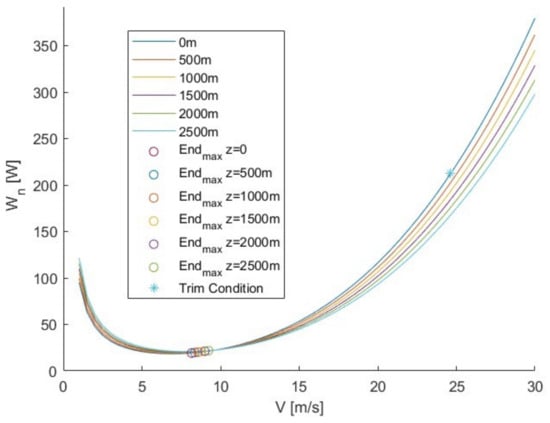
Figure 17.
Aircraft power required curves (HT with NACA 0012 + ) at studied altitudes.
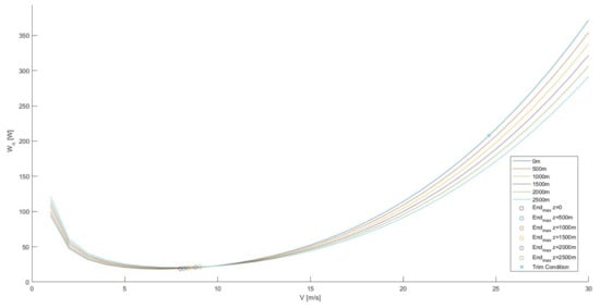
Figure 18.
Aircraft power required curves (HT with morphing airfoil) at studied altitudes.
Comparing Figure 17 and Figure 18, it can be seen that the morphing aircraft increase the endurance at all considered altitudes.
Figure 19 shows a detail of Figure 18 focused on trim speed. It can be seen that at the same altitude and , the aircraft with the airfoil morphing in the HT needs less power than the aircraft in traditional configuration.
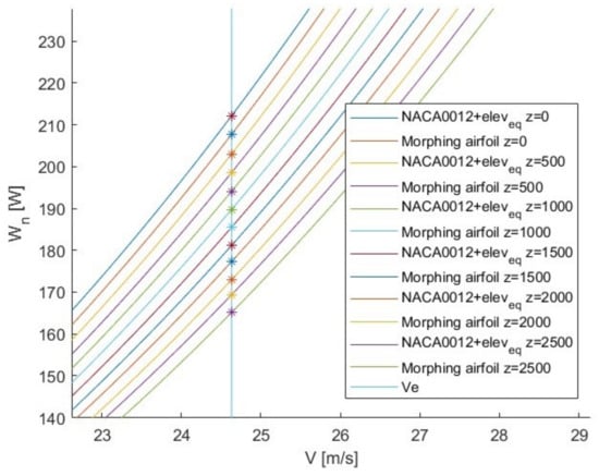
Figure 19.
Detail of aircraft power required curves at the studied altitudes.
7. Discussion
In the present work, a feasibility study is conducted to evaluate any potential improvements brought by replacing the conventional elevator of a reference UAV with a morphing horizontal tail.
Firstly, the aircraft model, its dynamics and the equilibrium condition, around which the entire study is based, has been implemented. Starting from the trim deflection of the elevator at equilibrium, through an experimental relationship, we obtained the camber that airfoil morphing must have to exactly replicate the effect of the elevator. At this point, to go back to the three-dimensional that was found for the airfoil, a comparison between the reference and the morphed aircraft has been made by analyzing the dynamic part, with the calculation of the transient characteristics of the longitudinal modes.
The results showed that the application of morphing improves the stability of the aircraft and, in particular, that of the short-period, improving its transient characteristics.
In addition, the following various improvements have been found in performance: starting from the aircraft’s up to the and aerodynamic efficiency, all aerodynamic parameters have undergone an improvement compared to reference aircraft.
It has been showed that, considering the same trim speed, at each considered altitude, the necessary power required by the morphing aircraft is significantly reduced, whereas the endurance is improved by more than 2.3% at various altitudes. Besides, th efficiency increase of about 1.8% that implies an improvement in aircraft range.
Future studies will be focused on morphing airfoils that produce the same tip deflection as the conventional elevator, as well as investigating the aircraft performance in conditions other than trim. Furthermore, further developments will regard a pull-up maneuver by comparing the achieved results and time between conventional and morphing tails.
Present work represents the first step towards a gust rejection procedure, in fact, airfoil modifications are morphing technologies that allow the change in the camber or the thickness of the wing profile during flight. This approach could be efficiently applied to gust alleviation modifying aerodynamic surfaces to generate an aerodynamic coefficient modification to contrast the wind-induced ones.
The final objective of these studies will be to develop an active system, coupled with the automatic gust identification system in [22], to reject gust effects on the unmanned vehicle performance.
Once the study of morphing tail is completed, the combined morphing wing–tail combinations will be analyzed.
Author Contributions
Conceptualization, F.M. and I.D.; methodology, F.M., I.D. and A.M.; validation, F.M. and I.D.; formal analysis, F.M. and A.M.;writing—original draft preparation, F.M., I.D. and A.M.; writing—review and editing, F.M., I.D. and A.M.; funding acquisition, F.M. and A.M. All authors have read and agreed to the published version of the manuscript.
Funding
FM acknowledge the support of the European Union through the FESR or FSE, PON Ricerca e Innovazione 2014–2020–DM 1062/1021 co-funding scheme.
Data Availability Statement
Data are contained within the article.
Conflicts of Interest
The authors declare no conflicts of interest.
References
- Yue, T.; Wang, L.; Ai, J. Multibody Dynamic Modeling and Simulation of a Tailless Folding Wing Morphing Aircraft. In Proceedings of the AIAA Atmospheric Flight Mechanics Conference, Minneapolis, MN, USA, 13–16 August 2012. [Google Scholar]
- Barbarino, S.; Bilgen, O.; Ajai, M.R.; Friswell, M.I.; Inman, D. A review of morphing aircraft. J. Intell. Mater. Syst. Struct. 2011, 22, 823–877. [Google Scholar] [CrossRef]
- Wolko, H.S.; Anderson, J.D. National Air and Space Museum. The Wright Flyer: An Engineering Perspective; Smithsonian: Washington, DC, USA, 1987. [Google Scholar]
- Brissenden, R.F.; Heath, A.R.; Conner, D.W.; Spearman, M.L. Assessment of variable camber for application to transport aircraft. In NASA Contractor Report CR-158930; National Aeronautics and Space Administration Langley Research Center: Hampton, VA, USA, 1980. [Google Scholar]
- Kudva, J.N.; Martin, C.A.; Scherer, L.B.; Jardine, A.P.; McGowan, A.M.R.; Lake, R.C.; Sendeckyj, G.P.; Sanders, B.P. Overview of the DARPA/AFRL/NASA smart wing program. In Smart Structures and Materials 1999: Industrial and Commercial Applications of Smart Structures Technologies; SPIE: Bellingham, WA, USA, 1999. [Google Scholar]
- Kintscher, M.; Kirn, J.; Storm, S.; Peter, F. Assessment of the SARISTU enhanced adaptive droop nose. In Smart Intelligent Aircraft Structures (SARISTU) Proceedings of the Final Project Conference; Springer International Publishing: Cham, Switerland, 2015. [Google Scholar]
- Concilio, A.; Dimino, I.; Pecora, R. SARISTU: Adaptive Trailing Edge Device (ATED) design process review. Chin. J. Aeronaut. 2021, 34, 187–210. [Google Scholar] [CrossRef]
- Wildschek, A.; Storm, S.; Herring, M.; Drezga, D.; Korian, V.; Roock, O. Design, optimization, testing, verification, and validation of the wingtip active trailing edge. In Smart Intelligent Aircraft Structures (SARISTU) Proceedings of the Final Project Conference; Springer International Publishing: Cham, Switerland, 2015. [Google Scholar]
- Amendola, G.; Dimino, I.; Amoroso, F.; Pecora, R. Experimental characterization of an adaptive aileron: Lab tests and FE correlation. In Proceedings of the Sensors and Smart Structures Technologies for Civil, Mechanical, and Aerospace Systems 2016, Las Vegas, NV, USA, 21–24 March 2016. [Google Scholar]
- Moens, F. Augmented Aircraft Performance with the Use of Morphing Technology for a Turboprop Regional Aircraft Wing. Biomimetics 2019, 4, 64. [Google Scholar] [CrossRef] [PubMed]
- Dimino, I.; Andreutti, G.; Moens, F.; Fonte, F.; Pecora, R.; Concilio, A. Integrated design of a morphing winglet for active load control and alleviation of turboprop regional aircraft. Appl. Sci. 2021, 11, 2439. [Google Scholar] [CrossRef]
- Valasek, J. Morphing Aerospace Vehicles and Structures; John Wiley & Sons: Hoboken, NJ, USA, 2012. [Google Scholar]
- Yao, Z.; Kan, Z.; Li, D. Gust Response of Spanwise Morphing Wing by Simulation and Wind Tunnel Testing. Aerospace 2023, 10, 328. [Google Scholar] [CrossRef]
- Beaverstock, C.S.; Ajaj, R.; Friswell, M.I.; Dettmer, W. Effect of span-morphing on the flight modes, stability & control. In Proceedings of the AIAA Guidance, Navigation, and Control (GNC) Conference, Boston, MA, USA, 19–22 August 2013; p. 4993. [Google Scholar]
- Ajaj, R.M.; Parancheerivilakkathil, M.S.; Amoozgar, M.; Friswell, M.I.; Cantwell, W.J. Recent developments in the aeroelasticity of morphing aircraft. Prog. Aerosp. Sci. 2021, 120, 100682. [Google Scholar] [CrossRef]
- Bishay, P.L.; Kok, J.S.; Ferrusquilla, L.J.; Espinoza, B.M.; Heness, A.; Buendia, A.; Zadoorian, S.; Lacson, P.; Ortiz, J.D.; Basilio, R.; et al. Design and Analysis of MataMorph-3: A Fully Morphing UAV with Camber-Morphing Wings and Tail Stabilizers. Aerospace 2022, 9, 382. [Google Scholar] [CrossRef]
- Cheng, G.; Ma, T.; Yang, J.; Chang, N.; Zhou, X. Design and Experiment of a Seamless Morphing Trailing Edge. Aerospace 2023, 10, 282. [Google Scholar] [CrossRef]
- Nicassio, F.; Scarselli, G. Simulation and Test of Discrete Mobile Surfaces for a RC-Aircraft. Aerospace 2019, 6, 122. [Google Scholar] [CrossRef]
- Obradovic, B.; Subbarao, K. Modeling and simulation of morphing wing aircraft. Morphing Aerosp. Veh. Struct. 2012, 48, 391–402. [Google Scholar]
- Drela, M. XFOIL: An analysis and design system for low Reynolds number airfoils. In Low Reynolds Number Aerodynamics, Proceedings of the Conference, Notre Dame, IN, USA, 5–7 June 1989; Springer: Berlin/Heidelberg, Germany, 1989. [Google Scholar]
- Etkin, B. Dynamics of Atmospheric Flight; John Wiley & Sons: Hoboken, NJ, USA, 1972. [Google Scholar]
- Grillo, C.; Montano, F. Wind component estimation for UAS flying in turbulent air. Aerosp. Sci. Technol. 2019, 93, 105317. [Google Scholar] [CrossRef]
Disclaimer/Publisher’s Note: The statements, opinions and data contained in all publications are solely those of the individual author(s) and contributor(s) and not of MDPI and/or the editor(s). MDPI and/or the editor(s) disclaim responsibility for any injury to people or property resulting from any ideas, methods, instructions or products referred to in the content. |
© 2024 by the authors. Licensee MDPI, Basel, Switzerland. This article is an open access article distributed under the terms and conditions of the Creative Commons Attribution (CC BY) license (https://creativecommons.org/licenses/by/4.0/).