Article

Precision Landing of Unmanned Aerial Vehicle under Wind Disturbance Using Derivative Sliding Mode Nonlinear Disturbance Observer-Based Control Method

Faculty of Smart Vehicle System Engineering, Chosun University, Dong-gu, Gwangju 61452, Republic of Korea
Aerospace 2024, 11(4), 265; https://doi.org/10.3390/aerospace11040265
Submission received: 18 January 2024 / Revised: 15 March 2024 / Accepted: 27 March 2024 / Published: 29 March 2024

Abstract

:
Unmanned aerial vehicles (UAVs) are extensively employed in civilian and military applications because of their excellent maneuverability. Achieving fully autonomous quadrotor flight and precision landing on a wireless charging station in the presence of wind disturbance has become a crucial research topic. This paper presents a composite control technique for UAV altitude and attitude tracking in harsh environments, i.e., wind disturbance. A composite controller was developed based on nonlinear disturbance observer (NDOB) control theory to allow the UAV to land in the presence of random external wind disturbances and ground effects. The NDOB estimated the unknown wind disturbance, and the estimation was fed into the derivative sliding mode nonlinear disturbance observer-based control (DSMNDOBC), allowing the UAV to perform autonomous precision landing. Two loop designs were applied: the inner loop for stabilization and the outer loop for altitude tracking. The quadrotor model dynamics and the proposed controller, DSMNDOBC, were simulated employing MATLAB/Simulink®, and the results were compared with the one obtained by the proportional derivative (PD) controller and the sliding mode controller (SMC). The simulation results indicated that the DSMNDOBC has superior altitude and attitude control compared to the PD and SMC controllers and better disturbance estimation and attenuation performance.

1. Introduction

1.1. Background

Unmanned aerial vehicles (UAVs) are utilized for various purposes, including military, civil engineering, and scientific applications such as delivery services, aerial mapping, surveillance, risk zone inspections, and search and rescue operations [1]. Researchers are paying considerable attention to UAVs because of their reliability, maneuverability, relevance in various applications, and affordability.
Quadrotors are an important subclass of UAVs with six degrees of freedom and four control inputs [2], typical of a coupled system with complex dynamics. This multiple-input and multiple-output system is highly nonlinear and underactuated, so excellent maneuverability is required for robust and autonomous mission completion, particularly during precision landing operations under the presence of wind disturbance for automated wireless charging mission.
The design and operation of complex systems involve two separate but connected fields: control systems and communication frameworks. A control system modifies variables to produce the desired performance or behavior. Typically, it comprises a plant, a controller, actuators, and sensors (the system being controlled) to attain desirable set-point values, stabilize the system’s behavior, and reduce the impact of disturbances. In contrast, the communication framework concerns the communication infrastructure, such as message formatting, error detection and repair, and data transport. Communication frameworks are generic and can be applied to many systems; however, control systems are intended for specific systems and applications.

1.2. Literature Review

Precisely landing a UAV at a wireless charging station (moving or stationary) in a harsh environment, particularly when random wind disturbance is present, is a daunting task. To land precisely on a target, a UAV must accurately follow its trajectory while maintaining stability. When designing precision landing controllers for quadrotors, complications such as ground effects and external disturbances (e.g., wind gusts) can arise [3]. To address this control problem, researchers have employed various control algorithms such as the proportional–integral–derivative (PID) controller [4], backstepping method [5], sliding mode control (SMC) [6], model predictive control (MPC) [7], and higher-order SMC [8]. However, many control techniques, such as PID control, SMC, and MPC, have primarily been employed to stabilize quadrotors equipped with numerous sensors, inertial measurement units, and cameras. Additional sensor installments on a UAV can result in the quadrotor system gaining additional weight and changing its center of gravity, mass, and inertia, leading to a higher chance of instability. Without eliminating the characteristics of ground effects and exterior disturbances, which are normally mixed with the control inputs, the prelisted controllers become ineffective in properly stabilizing the UAV’s flight motion, resulting in unexpected accidents. The disturbances must be measured to ensure the stability and resilience of the system. Therefore, designing high-performance quadrotor controllers remains challenging for researchers [9].
An optical-flow-based approach that adjusts controller gains was proposed for UAV landing [10]. A velocity vector field method was proposed in [11]. However, these studies were based on UAVs landing on fixed flat platforms. Cabecinhas et al. [12] proposed a robust control method that enabled the landing of a quadrotor on a slope. Ho et al. [13] introduced a method for landing UAVs by addressing the essential selection gain, a problem associated with optical-flow-based UAV landings. To overcome this challenge, Ho et al. [13] utilized a camera to estimate the ground orientation and an adaptive gain selection controller.
Algorithms for landing on stationary platforms have attracted research attention, but they cannot achieve landing in motion. The challenge of landing on mobile platforms was studied in [14], and a vision-based solution was proposed to address the challenge of a quadrotor landing on a vertically moving platform. However, the study was irrelevant to outdoor activities, because a motion capture technique was adopted. In another study [15], global positioning system (GPS) navigation was employed to allow a quadrotor to land employing a backstepping controller. Positioning is the primary factor that significantly influences the effectiveness of UAVs landing. Despite being widely utilized for locating UAVs outdoors [16], GPS suffers significantly in clustering situations, such as densely populated cities, confined valleys, and dense woods.
In addition, in caves and interior spaces with poor GPS reception, ultrasonic rangers, laser rangers, light detection and ranging sensors, and visual cameras are the additional onboard sensors that are most often utilized by researchers [17]. An online UAV altitude control technique is proposed to minimize the expected weighted sum age of information for Internet of Things (IoT) devices, with timely data delivery before the data become outdated and lose value [18]. Moreover, it leverages the IoT for an efficient and fast transfer of data between the mission computer and the UAV [19,20]. By contrast, other methods focus on improving the landing target state estimation.
All the studies discussed above emphasized the role of a robust controller in the precision landing of quadrotors. When designing a robust controller during the precision landing procedure, it is necessary to carefully analyze external random wind disturbances and ground effects, which are the main variables affecting the low-altitude flying performance of quadrotors.

1.3. Contribution

This paper presents a derivative-sliding-mode nonlinear disturbance-observer-based control (DSMNDOBC) method for altitude and attitude control of UAVs in the presence of ground effects and random wind disturbances. The main contributions of this study are as follows:
  • We explored a nonlinear disturbance observer (NDOB) to design a DSMNDOBC. A derivative function is combined with the SMC to achieve dynamic and robust control. The derivative function can cancel out the overshoot effect, allowing the modeled system to achieve a satisfactory control performance. The SMC component has a fast dynamic response and immunity to changes in plant factors and provides an integration platform for estimated disturbance, such as random wind disturbance.
  • The integrated NDOB has a low computational demand, with no need for supplementary sensors that can estimate and generate corrective control inputs for the annulment of random external disturbance effects.
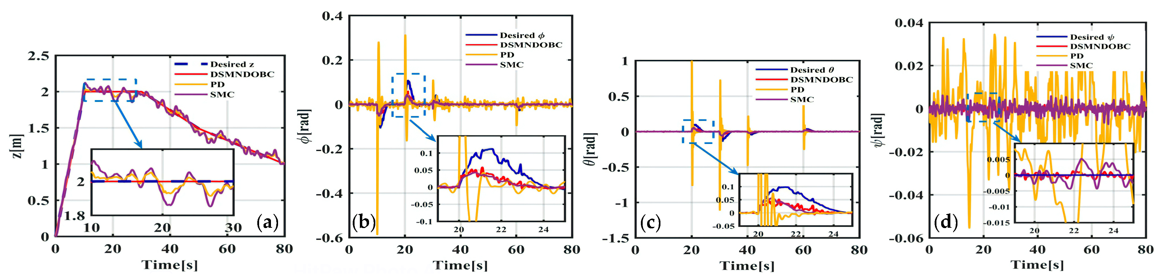
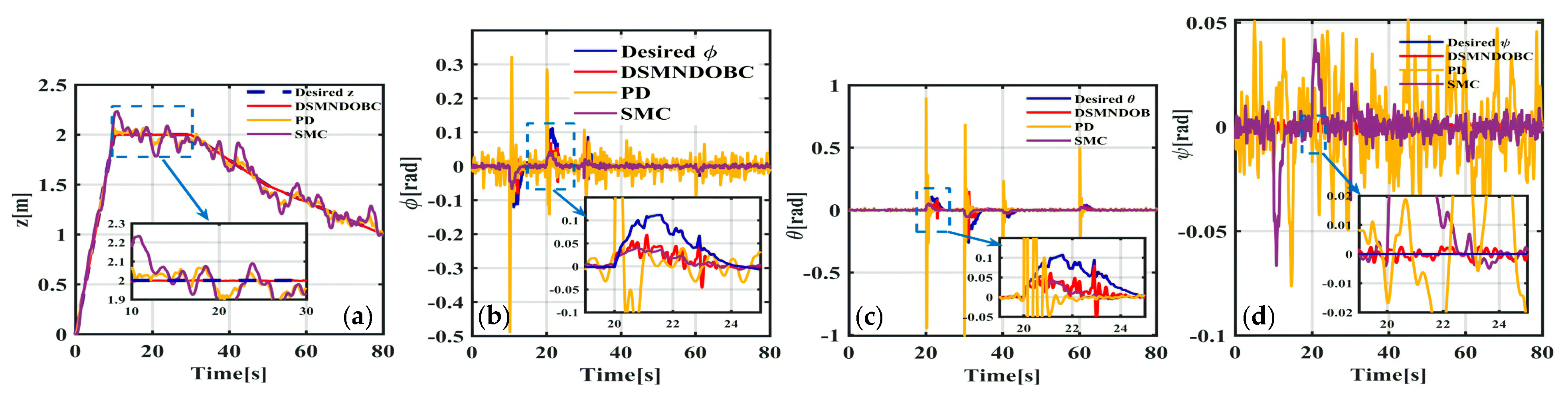
  • In numerical simulations, the proposed DSMNDOBC outperformed conventional proportional–derivative (PD) and SMC controllers with regard to altitude and attitude tracking.

1.4. Article Organization

The remainder of this paper is organized as follows: Section 2 presents the general quadrotor model. Section 3 presents the problem formulation, adopting the DSMNDOBC design process for altitude and attitude tracking. The simulation results are presented in Section 4. Finally, the conclusions and future research directions are presented in Section 5.

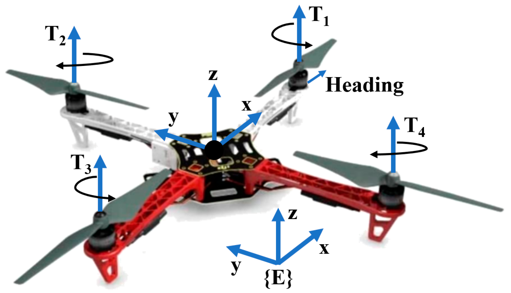
2. Quadrotor Dynamics

Quadrotors (Figure 1) are aerial robotic systems with complex nonlinear dynamic models. A quadrotor is powered by four motors to generate thrust T i   ( i = 1 , , 4 ) , which are grouped in relation to the command inputs and full-vehicle dynamics, as expressed in Equations (1)–(10) [9,21].
U 1 = T 1 + T 2 + T 3 + T 4 ,
U 2 = l T 2 T 4 ,
U 3 = l T 3 T 1 ,
U 4 = C f m T 1 + T 2 T 3 + T 4 ,
ϕ ¨ = I y I z I x θ ˙ ψ ˙ + l l x U 2 ,
θ ¨ = I z I x I y ϕ ˙ ψ ˙ + l l y U 3 ,
ψ ¨ = I x I y I z θ ˙ ϕ ˙ + l l z U 4 ,
x ¨ = U 1 M sin ϕ sin ψ + cos ϕ sin θ cos ψ ,
y ¨ = U 1 M cos ϕ sin θ cos ψ + sin ϕ cos ψ ,
z ¨ = g + U 1 M cos ϕ cos θ ,
where x , y , and z represent the position of the quadrotor in the inertia frame {E} ( m ); ϕ , θ , and ψ represent the orientation of the quadrotor in the inertial frame {E} ( r a d ); M represents the vehicle mass ( k g ); g represents the gravitational acceleration ( m / s 2 ); l represents the arm length ( m );  I x , I y , and I z represent the moment of inertia ( k g m 2 ); and C f m represents the force-to-moment coefficient (no unit).

3. Precision Landing Control

Considering the combined effects of external disturbances such as low visibility, wind gusts, and risky deck motion, it is difficult to satisfy the performance requirements of precision landing. The precise landing of UAVs requires deploying a strong controller that can cancel the effects of inherent and exogenous disturbances while providing stability and a good dynamic response. To build a strong control system for precision landing, external disturbances and ground effects were considered by employing a nonlinear disturbance-observer-based control (NDOBC). The NDOBC can handle uncertainty, underactuation, and disturbances in the system and can be seamlessly integrated with many nonlinear control laws to achieve robustness [22,23].
The NDOBC design approach was as follows:
(1)
A nonlinear composite controller centered on the SMC was designed to attain stability and satisfy additional performance requirements, with the hypothesis that the disturbance is quantifiable.
(2)
An NDOB was then built to estimate the disturbance.
(3)
The disturbance observer was integrated with a nonlinear controller by substituting the observer’s disturbance estimation into the control law.
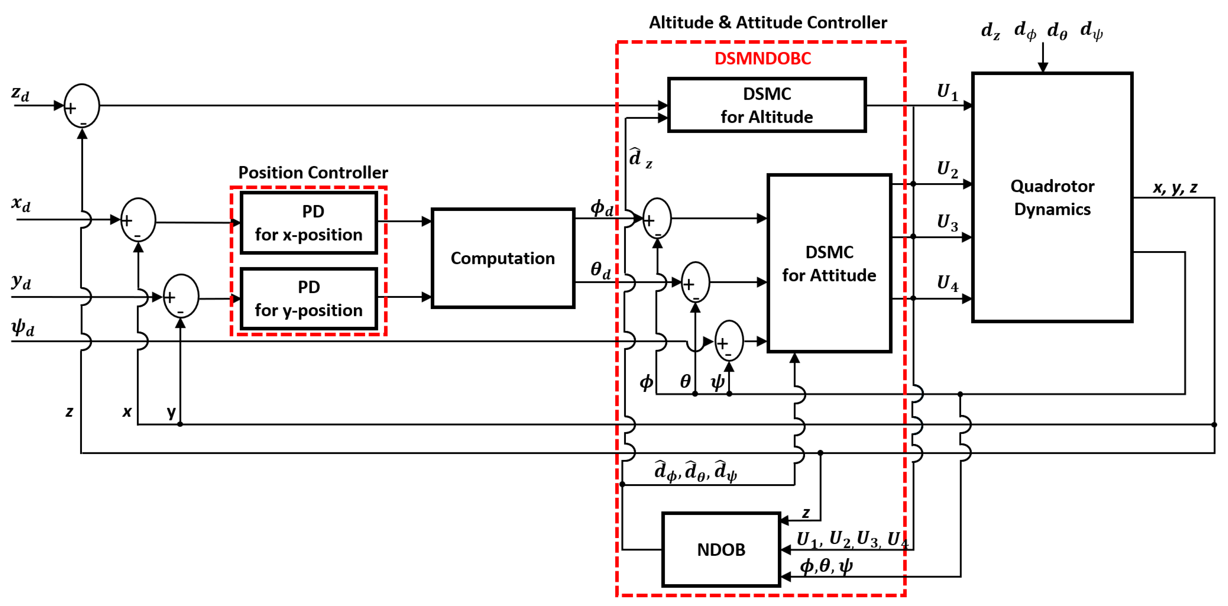
Considering an unknown external wind disturbance (with unknown amplitude), the equations of motion for the quadrotor along the vertical, roll, pitch, and yaw axes are as follows:
z ¨ = g + δ M cos ϕ cos θ U 1 + d z ,
ϕ ¨ = I y I z I x θ ˙ ψ ˙ + l I x U 2 + d ϕ ,
θ ¨ = I z I x I y θ ˙ ψ ˙ + l I y U 3 + d θ ,
ψ ¨ = I x I y I z θ ˙ ϕ ˙ + l I z U 4 + d ψ ,
δ = 1 r 2 ( 4 z r ) 2 r 2 z r d h 2 + 4 d v 2 3 r 2 z r 2 2 d h 2 + 4 d v 2 3 1 ,
where d z , d ϕ , d θ , and d ψ denote the wind disturbances ( m / s and r a d / s ); r represents the rotor radius ( m ); d h represents the horizontal distance between two opposite rotor axes in a diagonal direction ( m ); d v represents the vertical distance from the propeller surface to the ground ( m ); and δ denotes the ground effects (no unit). The additional term in the denominator represents the aerodynamic interference of other rotors [24]. The NDOB was introduced to estimate unknown disturbances, adopting the internal state variable z n d o , as described in the following section.

3.1. DSMNDOBC

The detailed mathematical derivations for achieving DSMNDOBC are presented in Figure 2.
(1)
NDOB
Consider a nonlinear system of the form
X ¨ = f x + g 1 x U + g 2 x d ,
Y = h x ,
where X , U , d , and Y denote the system state (no unit), the input vector ( k g · m / s 2 ), exogenous wind disturbance ( m / s ), and the output vector (no unit), respectively. The terms f , g 1 , g 2 , and h are smooth functions with respect to x . Furthermore, an external disturbance d can be generated by the system as follows:
ξ ˙ = A ξ ,
d = C ξ .
The general form of the nonlinear disturbance observer is
z ˙ n d o = A η g 2 ( x ) C z n d o + A p ( x ) η g 2 ( x ) C p ( x ) + f ( x ) + g 1 ( x ) U ,
ξ ^ = z n d o + p x ,
d ^ = C ξ ^ ,
p x = η x ,
where z n d o is the internal state variable of the NDOB ( m ), ξ ^ is the auxiliary variable of the observer ( m ), p and η denote the nonlinear function and the observer gain to be selected, respectively (no unit), d ^ denotes the disturbance observer estimation ( m / s ), A is an m × m matrix representing the frequency of the external disturbance ( s 1 ) [22], and C is a 1 × m row matrix (no unit). Here, A and C are defined as
A = 0 ω 0 ω 0 0   and   C = 1 0 ,
and the nonlinear observer gain η is estimated as follows:
e ˙ n d o = A η g 2 x C e n d o ,
where e n d o represents the estimation error of the NDOB ( s 1 ). The above equations ensure the global exponential stability of the closed-loop system, regardless of disturbances [25]. Here, the concept of the NDOB is briefly presented. Comprehensive theoretical details can be found in [22,25], where the NDOB is defined for the axes being considered.
Comparing Equation (11) with Equation (16) for the vertical dynamics gives
g 1 x = δ M cos ϕ cos θ ,
g 2 ( x ) = 1 ,
f x = g .
From Equations (20) and (26)–(28), z ˙ n d o , z can be obtained as
z ˙ n d o , z = A η z C z n d o , z + A η z z η z η z z g + δ M cos ϕ cos θ U 1 .
Similarly, the NDOBs for the attitude dynamics are obtained as follows:
z ˙ n d o , ϕ = A η ϕ C z n d o , ϕ + A η ϕ ϕ η ϕ η ϕ ϕ + I y I z I x θ ˙ ψ ˙ + l I x U 2 ,
z ˙ n d o , θ = A η θ C z n d o , θ + A η θ θ η θ η θ θ + I z I x I y ϕ ˙ ψ ˙ + l I y U 3 ,
z ˙ n d o , ψ = A η ψ C z n d o , ψ + A η ψ ψ η ψ η ψ ψ + I x I y I z θ ˙ ϕ ˙ + l I z U 4 .
(2)
DSMC
Derivative sliding mode control (DSMC) is adopted for a quadrotor’s altitude and attitude trajectory tracking under the influence of ground effects and random wind disturbances. The tracking error for the motion along the vertical axis is given by
e z = z d z .
For any constant k 1 , the sliding mode surface and its derivative are given as
s z = e ˙ z k 1 e z ,
s ˙ z = e ¨ z k 1 e ˙ z .
The controller inputs U i   ( i = 1 , , 4 ) are a composite of the sliding mode control law with a derivative component:
U 1 = m δ cos ϕ cos θ ( z ¨ d + g d ^ z + k 1 , z e ˙ z + k 2 , z S z + ς z e ˙ z ) ,
U 2 = I x l ϕ ¨ d I y I z I x θ ˙ ψ ˙ d ^ ϕ + k 1 , ϕ e ˙ ϕ + k 2 , ϕ S ϕ + ς ϕ e ˙ ϕ ,
U 3 = I y l θ ¨ d I z I x I y ϕ ˙ ψ ˙ d ^ θ + k 1 , θ e ˙ θ + k 2 , θ S θ + ς θ e ˙ θ ,
U 4 = I z l ψ ¨ d I x I y I z ϕ ˙ θ ˙ d ^ ψ + k 1 , ψ e ˙ ψ + k 2 , ψ S ψ + ς ψ e ˙ ψ .

3.2. PD Controller

Position tracking was achieved by implementing PD controllers as described below. The tracking errors for the x and y positions are defined as follows:
e x = x d x   and   e y = y d y ,
U x = k p , x e x k d , x x ˙   and   U y = k p , y e y k d , y y ˙ .
From Equation (8), θ d was derived as
θ d = sin 1 M U 1 U x sin ϕ sin ψ cos ϕ cos ψ .
Similarly, from Equations (9) and (10), ϕ d was computed as follows:
ϕ d = sin 1 M U 1 z ¨ + g tan θ sin ψ U y cos ϕ cos ψ
where ( x d , y d , ϕ d , θ d ) and ( x ,   y ,   ϕ ,   θ ) are the desired and current values, respectively, and k p and k d are the proportional and derivative gains to be determined (no unit).

4. Simulation Results

4.1. Environmental Setup

The performance of the proposed composite control technique, DSMNDOBC, was evaluated utilizing numerical simulations in a MATLAB/Simulink® environment. The results of the DSMNDOBC method were compared with those of the SMC and PD control methods. The performance of the controllers was judged by taking the root-mean-square error of the quadrotor trajectory tracking in the z , ϕ , θ , and ψ directions.
A random wind profile was generated, with mean wind speeds of 10 and 20 m / s , utilizing the Dryden continuous wind turbulence model [26]. A Dryden wind model block was employed to generate the atmospheric turbulence. White noise was passed through a filter to provide turbulence to the specified velocity spectra. The effects of turbulence on a moving body such as an aircraft were modeled by producing time-varying wind gusts.
In MATLAB/Simulink®, the Dryden wind model was implemented as a block in the Simulink Library. In this Simulink block, a parameter called “mean wind speed” (representing the resultant wind velocity in the body axis frame) was employed to output time-varying wind gusts (turbulence velocities in x , y , and z and turbulence angular rates in ϕ , θ , and ψ ). The model utilized a random number generator to produce a wind disturbance. In our simulations, mean wind speeds of 10 and 20 m / s were utilized, corresponding to maximum wind turbulence velocity amplitudes (in the z-axis) of 5.24 and 10.27 m / s , respectively.
Each DSMNDOBC was subjected to a sample wind profile, as illustrated in Figure 3. Figure 4 presents the disturbance estimates, with the generated disturbances indicated by red lines. The NDOB accurately estimated the disturbances in the system and contributed to the overall performance of the proposed controller.

4.2. Scenario

A total of three scenarios based on two different trajectories (linear and circular) were employed to evaluate the three control methods (DSMNDOBC, PD, and SMC) by introducing three uncertainty media (sensor noise, model uncertainty, and wind turbulence). The quality of the trajectory tracking response of the quadrotor was evaluated based on the root-mean-square error ( E R M S ) and maximum error ( E M A X ) along the altitude and attitude positions.
(1)
Scenario 1
In the first scenario, the performance of the DSMNDOBC was evaluated while the quadrotor tracked a predetermined line trajectory at an altitude of 2 m under wind disturbance conditions of 10 and 20 m / s for 80 s with a sample time of 0.01 s . The E R M S and E M A X results are presented in Table 1 and Table 2, respectively, and the simulation results are presented in Figure 5, Figure 6 and Figure 7.
(2)
Scenario 2
In the second scenario, a circular trajectory was adopted to assess the performance of the proposed DSMNDOBC under two environmental conditions at the same wind speed. The time-varying feature of a circular trajectory with a sample rate of 100 is mathematically described as ω = 0.01 : π 100 : 2 π , x , y , z = 20 sin ω , 20 cos ω , 1.9 , and T = 0 : 0.1 : 21 . The transient response was tracked along the desired height of 1.9 m with a circular trajectory of a radius of 20 m . The simulation time was 2100 s .
Table 3 and Table 4 present the E R M S and E M A X values for the altitude and attitude positions, respectively, over the simulation period. This result reinforces the fact that the DSMNDOBC provides excellent tracking performance compared to the PD and SMC controllers. The simulation results are presented in Figure 8, Figure 9 and Figure 10.
(3)
Scenario 3
In the third scenario, for further robustness analysis of the three control methods, three uncertainty media (sensor noise, model uncertainty, and wind turbulence) were combined and introduced into the simulation with the same line trajectory as in Scenario 1.
First, white Gaussian noise with zero mean was created to simulate sensor noise. For a sampling time of 0.01 s , the variance in the generated noise for the altitude motion was 0.5 and 0.2 for attitude motion tracking, considering that a GPS sensor could have an accuracy of 0.025 m [27].
Second, for the introduction of model uncertainties, a variation of ±50% was assumed for the mass of the quadrotor ( M ), and the inertia ( I x , I y , I z ) was allowed to vary by ±20%.
Third, wind turbulence with an amplitude of 10.14 m/s was introduced to analyze the robustness against exogenous wind disturbances.
The trajectory performance analysis results are presented in Table 5 and Table 6.
The proposed controller was further quantified utilizing the mean wind speeds of 22, 24, 26, and 28 m / s to determine the maximum disturbance boundary for the controller. The maximum disturbance bound was 26 m / s . The system diverged at 27 m / s , corresponding to a wind turbulence velocity amplitude of 13.96 m / s .
Although DSMNDOBC seems to result in similar values of both E R M S and E M A X under ±50% of the mass variation, a big difference is observed in both the PD and SMC cases for all investigation samples ( z , ϕ , θ , and ψ ). This indicates that the DSMNDOBC has superior control, disturbance estimation, and attenuation performance compared with the PD and SMC controllers.

5. Conclusions

Here, a composite controller was designed utilizing the NDOBC approach to estimate and attenuate the exogenous (wind) and ground effect disturbances that negatively influence quadrotor dynamics. Because a quadrotor is an underactuated system, two loop designs were considered in the algorithm. Stabilization was performed in the inner loop and altitude tracking was performed in the outer loop.
In simulations based on the MATLAB/Simulink® environment, the proposed composite control technique exhibited a robust performance, as it moved precisely along the specified route when subjected to various wind disturbances. The simulation results indicate that the DSMNDOBC has superior altitude and attitude control and better disturbance estimation and attenuation performance than the PD and SMC controllers. The performance of the DSMNOBC was better, more stable, and more robust. Overall, a UAV with a 2.7 kg mass subjected to a fairly violent turbulence profile provides such an attenuated response, especially considering the sensor noise and model uncertainty in close proximity to the ground.
In the future, the designed controller will be tested on an experimental quadrotor platform for multiple applications, such as autonomous precision landing in harsh environments. Also, we plan to replace the PD controller with the DSMNDOBC to improve the x and y position accuracy by solving the unwanted disturbance estimation errors, bringing improved accuracy to the estimation of roll and pitch angles.

Funding

This study was supported by a research fund from Chosun University, 2023, under Grant K208419004.

Data Availability Statement

The data presented in this study are available on request from the corresponding author due to privacy reasons.

Conflicts of Interest

The author declares no conflicts of interest.

Acronyms

DSMCDerivative sliding mode control
DSMNDOBCDerivative-sliding-mode nonlinear disturbance-observer-based control
GPSGlobal positioning system
MPCModel predictive control
NDOBNonlinear disturbance observer
NDOBCNonlinear disturbance-observer-based control
PDProportional derivative
PIDProportional–integral–derivative
SMCSliding mode control
UAVUnmanned aerial vehicle

Nomenclature

C f m Force-to-moment coefficient N o   U n i t
d h Horizontal distance between two opposite rotor axes m 0.32
d v Vertical distance from the propeller surface to the ground m 0.65
d z , d ϕ , d θ , d ψ External wind disturbance m / s and r a d / s
d ^ ϕ , d ^ θ , d ^ ψ Disturbance observer estimation m / s
δ Ground effects N o   U n i t
e n d o Estimation error of NDOB s 1
f Smooth function N o   U n i t
g 1 Smooth function N o   U n i t
g 2 Smooth function N o   U n i t
h Smooth function N o   U n i t
g Gravitational acceleration m / s 2 9.81
I x , I y , I z Inertial momentum k g · m 2 0.0173, 0.0173, 0.0223
k 1 , z , k 1 , ϕ , k 1 , θ , k 1 , ψ Controller gain of DSMNDOBC N o   U n i t 5, 5, 5, 5
k 2 , z , k 2 , ϕ , k 2 , θ , k 2 , ψ Controller gain of DSMNDOBC N o   U n i t 30, 10, 10, 10
ς z , ς ϕ , ς θ , ς ψ Controller gain of DSMNDOBC N o   U n i t 50, 10, 10, 10
η z , η ϕ , η θ , η ψ Observer gain of DSMNDOBC N o   U n i t 30, 30, 30, 30
k d , x , k d , y Controller gain of PD N o   U n i t 4.0, 3.5
k p , x , k p , y Controller gain of PD N o   U n i t 3.5, 4.0
l Arm length m 0.225
M Quadrotor mass k g 2.7
p Nonlinear function N o   U n i t
r Rotor radius m 0.127
T Time of arrival s
U Input vector k g · m / s 2
ω 0 Frequency of the external wind disturbance s 1
X State vector N o   U n i t
Y Output vector N o   U n i t
x ,   y ,   z Positions of the UAV in the inertial frame m
ϕ , θ , ψ Orientation of the UAV in the inertial frame r a d
x d , y d Desired positions of the UAV in the inertial frame m
ϕ d , θ d Desired orientation of the UAV in the inertial frame r a d
z n d o Internal state variable of NDOB m
ξ ^ Auxiliary variable of NDOB m

References

  1. Bashi, O.I.D.; Hasan, W.Z.W.; Azis, N.; Shafie, S.; Wagatsuma, H. Unmanned Aerial Vehicle Quadcopter: A Review. J. Comput. Theor. Nanosci. 2017, 14, 5663–5675. [Google Scholar] [CrossRef]
  2. Kangunde, V.; Jamisola, R.S.; Theophilus, E.K. A review on drones controlled in real-time. Int. J. Dyn. Control 2021, 9, 1832–1846. [Google Scholar] [CrossRef]
  3. Sun, C.; Liu, M.; Liu, C.; Feng, X.; Wu, H. An Industrial Quadrotor UAV Control Method Based on Fuzzy Adaptive Linear Active Disturbance Rejection Control. Electronics 2021, 10, 376. [Google Scholar] [CrossRef]
  4. Wang, S.; Polyakov, A.; Zheng, G. Quadrotor stabilization under time and space constraints using implicit PID controller. J. Frankl. Inst. 2022, 359, 1505–1530. [Google Scholar] [CrossRef]
  5. Koksal, N.; An, H.; Fidan, B. Backstepping-based adaptive control of a quadrotor UAV with guaranteed tracking performance. ISA Trans. 2020, 105, 98–110. [Google Scholar] [CrossRef]
  6. Mechali, O.; Xu, L.; Xie, X.; Iqbal, J. Theory and practice for autonomous formation flight of quadrotors via distributed robust sliding mode control protocol with fixed-time stability guarantee. Control Eng. Pract. 2022, 123, 105150. [Google Scholar] [CrossRef]
  7. Michel, N.; Bertrand, S.; Olaru, S.; Valmorbida, G.; Dumur, D. Design and flight experiments of a Tube-Based Model Predictive Controller for the AR.Drone 2.0 quadrotor. IFAC-PapersOnLine 2019, 52, 112–117. [Google Scholar] [CrossRef]
  8. Chandra, A.; Lal, P.P. Higher Order Sliding Mode Controller for a Quadrotor UAV with a Suspended Load. IFAC-PapersOnLine 2022, 55, 610–615. [Google Scholar] [CrossRef]
  9. Xuan-Mung, N.; Hong, S.K.; Nguyen, N.P.; Ha, L.N.N.T.; Le, T.-L. Autonomous Quadcopter Precision Landing onto a Heaving Platform: New Method and Experiment. IEEE Access 2020, 8, 167192–167202. [Google Scholar] [CrossRef]
  10. Hordijk, B.J.P.; Scheper, K.Y.W.; de Croon, G.C.H.E. Vertical landing for micro air vehicles using event-based optical flow. J. Field Robot. 2017, 35, 69–90. [Google Scholar] [CrossRef]
  11. Goncalves, V.M.; McLaughlin, R.; Pereira, G.A.S. Precise Landing of Autonomous Aerial Vehicles Using Vector Fields. IEEE Robot. Autom. Lett. 2020, 5, 4337–4344. [Google Scholar] [CrossRef]
  12. Cabecinhas, D.; Naldi, R.; Silvestre, C.; Cunha, R.; Marconi, L. Robust Landing and Sliding Maneuver Hybrid Controller for a Quadrotor Vehicle. IEEE Trans. Control Syst. Technol. 2016, 24, 400–412. [Google Scholar] [CrossRef]
  13. Ho, H.W.; de Croon, G.C.H.E.; van Kampen, E.; Chu, Q.P.; Mulder, M. Adaptive Gain Control Strategy for Constant Optical Flow Divergence Landing. IEEE Trans. Robot. 2018, 34, 508–516. [Google Scholar] [CrossRef]
  14. Hu, B.; Lu, L.; Mishra, S. A Control Architecture for Time-Optimal Landing of a Quadrotor onto a Moving Platform. Asian J. Control 2018, 20, 1701–1712. [Google Scholar] [CrossRef]
  15. Ghommam, J.; Saad, M. Autonomous Landing of a Quadrotor on a Moving Platform. IEEE Trans. Aerosp. Electron. Syst. 2017, 53, 1504–1519. [Google Scholar] [CrossRef]
  16. Liu, W.; Li, Z.; Sun, S.; Gupta, M.K.; Du, H.; Malekian, R.; Sotelo, M.A.; Li, W. Design a Novel Target to Improve Positioning Accuracy of Autonomous Vehicular Navigation System in GPS Denied Environments. IEEE Trans. Ind. Inform. 2021, 17, 7575–7588. [Google Scholar] [CrossRef]
  17. Hentschke, M.; de Freitas, E.P.; Hennig, C.H.; da Veiga, I.C.G. Evaluation of Altitude Sensors for a Crop Spraying Drone. Drones 2018, 2, 25. [Google Scholar] [CrossRef]
  18. Samir, M.; Assi, C.; Sharafeddine, S.; Ghrayeb, A. Online Altitude Control and Scheduling Policy for Minimizing AoI in UAV-assisted IoT Wireless Networks. IEEE Trans. Mob. Comput. 2022, 21, 2493–2505. [Google Scholar] [CrossRef]
  19. Yang, L.; Yao, H.; Wang, J.; Jiang, C.; Benslimane, A.; Liu, Y. Multi-UAV-Enabled Load-Balance Mobile-Edge Computing for IoT Networks. IEEE Internet Things J. 2020, 7, 6898–6908. [Google Scholar] [CrossRef]
  20. Fang, Z.; Wang, J.; Ren, Y.; Han, Z.; Poor, H.V.; Hanzo, L. Age of Information in Energy Harvesting Aided Massive Multiple Access Networks. IEEE J. Sel. Areas Commun. 2022, 40, 1441–1456. [Google Scholar] [CrossRef]
  21. Jung, S.; Ariyur, K.B. Strategic Cattle Roundup using Multiple Quadrotor UAVs. Int. J. Aeronaut. Space Sci. 2017, 18, 315–326. [Google Scholar] [CrossRef]
  22. Chen, W.-H. Nonlinear Disturbance Observer Based Control for Nonlinear Systems with Harmonic Disturbances. IFAC Proc. Vol. 2001, 34, 329–334. [Google Scholar] [CrossRef]
  23. Zhang, H.; Wei, X.; Zhang, L.; Tang, M. Disturbance rejection for nonlinear systems with mismatched disturbances based on disturbance observer. J. Frankl. Inst. 2017, 354, 4404–4424. [Google Scholar] [CrossRef]
  24. Sanchez-Cuevas, P.; Heredia, G.; Ollero, A. Characterization of the Aerodynamic Ground Effect and Its Influence in Multirotor Control. Int. J. Aerosp. Eng. 2017, 2017, 1823056. [Google Scholar] [CrossRef]
  25. Li, S.; Yang, J.; Chen, W.H.; Chen, X. Disturbance Observer-Based Control: Methods and Applications, 1st ed.; CRC Press—Taylor & Francis Group: New York, NY, USA, 2014; pp. 137–156. [Google Scholar]
  26. The Mathworks, Inc. Dryden Wind Turbulence Model (Continuous). Help Center. Available online: https://www.mathworks.com/help/aeroblks/drydenwindturbulencemodelcontinuous.html (accessed on 5 October 2023).
  27. Cahyadi, M.N.; Asfihani, T.; Mardiyanto, R.; Erfianti, R. Performance of GPS and IMU sensor fusion using unscented Kalman filter for precise i-Boat navigation in infinite wide waters. Geodesy Geodyn. 2023, 14, 265–274. [Google Scholar] [CrossRef]
Figure 1. Quadrotor configuration.
Aerospace 11 00265 g001
Figure 2. Proposed DSMNDOBC block diagram.
Aerospace 11 00265 g002
Figure 3. Wind disturbance profiles generated with mean wind speed of 20 m / s : (a) d z , (b) d ϕ , (c) d θ , and (d) d ψ .
Aerospace 11 00265 g003
Figure 4. Wind disturbance estimation of the wind profile generated with a mean wind speed of 20 m / s : (a) d z , (b) d ϕ , (c) d θ , and (d) d ψ .
Aerospace 11 00265 g004
Figure 5. Scenario 1 simulation results for altitude and attitude position tracking under mean wind speed of 10 m / s : (a) z , (b) ϕ , (c) θ , and (d) ψ .
Aerospace 11 00265 g005
Figure 6. Scenario 1 simulation results for altitude and attitude position tracking under mean wind speed of 20 m / s : (a) z , (b) ϕ , (c) θ , and (d) ψ .
Aerospace 11 00265 g006
Figure 7. Three-dimensional trajectory tracking performance for Scenario 1 in the presence of random wind disturbance: (a) 10 m / s and (b) 20 m / s .
Aerospace 11 00265 g007
Figure 8. Scenario 2 simulation results for altitude and attitude position tracking under mean wind speed of 10 m / s : (a) z , (b) ϕ , (c) θ , and (d) ψ .
Aerospace 11 00265 g008
Figure 9. Scenario 2 simulation results for altitude and attitude position tracking under mean wind speed of 20 m / s : (a) z , (b) ϕ , (c) θ , and (d) ψ .
Aerospace 11 00265 g009
Figure 10. Three-dimensional trajectory tracking performance for Scenario 2 in the presence of random wind disturbance: (a) 10 m / s and (b) 20 m / s .
Aerospace 11 00265 g010
Table 1. E R M S for quadrotor position (Scenario 1).
Condition E R M S DSMNDOBCPDSMC
10 m / s z   ( m ) 0.00090.03450.0574
ϕ   ( r a d ) 0.00930.03970.0087
θ   ( r a d ) 0.01500.07080.0159
ψ   ( r a d ) 0.00070.01490.0021
20 m / s z   ( m ) 0.00110.04990.0932
ϕ   ( r a d ) 0.01630.04880.0171
θ   ( r a d ) 0.02280.07520.0234
ψ   ( r a d ) 0.00140.02010.0033
Table 2. E M A X for quadrotor position (Scenario 1).
Condition E M A X DSMNDOBCPDSMC
10 m / s z   ( m ) 0.00610.09130.1477
ϕ   ( r a d ) 0.06870.58620.0526
θ   ( r a d ) 0.11581.09380.0807
ψ   ( r a d ) 0.00280.05540.0073
20 m / s z   ( m ) 0.00650.14520.2361
ϕ   ( r a d ) 0.11220.47110.0941
θ   ( r a d ) 0.31670.99280.2107
ψ   ( r a d ) 0.00560.07640.0119
Table 3. E R M S for quadrotor position (Scenario 2).
Condition E R M S DSMNDOBCPDSMC
10   m / s z   ( m ) 0.00060.03740.0606
ϕ   ( r a d ) 0.02150.03130.0490
θ   ( r a d ) 0.01460.04080.0278
ψ   ( r a d ) 0.00070.01860.0209
20   m / s z   ( m ) 0.00090.05410.0936
ϕ   ( r a d ) 0.02350.03640.0609
θ   ( r a d ) 0.02230.04650.0364
ψ   ( r a d ) 0.00130.02410.0265
Table 4. E M A X for quadrotor position (Scenario 2).
Condition E M A X DSMNDOBCPDSMC
10   m / s z   ( m ) 0.00200.12830.2050
ϕ   ( r a d ) 0.53110.46430.7864
θ   ( r a d ) 0.41552.57100.6076
ψ   ( r a d ) 0.00290.08270.0923
20   m / s z   ( m ) 0.00330.19490.3365
ϕ   ( r a d ) 0.88451.45600.8014
θ   ( r a d ) 2.85602.30600.7014
ψ   ( r a d ) 0.00570.10340.1150
Table 5. E R M S for quadrotor position (Scenario 3).
Condition E R M S DSMNDOBCPDSMC
M : +50%
I x , I y , I z : +20%
z 0.00110.05040.0905
ϕ 0.01540.05300.0163
θ 0.01410.08100.0157
ψ 0.00140.02400.0033
M : −50%
I x , I y , I z : −20%
z 0.00110.05100.0905
ϕ 0.01520.04440.0162
θ 0.01410.06810.0158
ψ 0.00140.01620.0033
Table 6. E M A X for quadrotor position (Scenario 3).
Condition E M A X DSMNDOBCPDSMC
M : +50%
I x , I y , I z : +20%
z 0.00660.14830.2298
ϕ 0.11000.47070.0936
θ 0.16911.04340.2513
ψ 0.00550.09130.0120
M : −50%
I x , I y , I z : −20%
z 0.00660.14770.2298
ϕ 0.10570.48370.1012
θ 0.16901.12070.2513
ψ 0.00540.06140.0120
Disclaimer/Publisher’s Note: The statements, opinions and data contained in all publications are solely those of the individual author(s) and contributor(s) and not of MDPI and/or the editor(s). MDPI and/or the editor(s) disclaim responsibility for any injury to people or property resulting from any ideas, methods, instructions or products referred to in the content.

