Abstract
The present paper investigates the design process and the dimensioning of a tailless type-C composite sandwich unmanned aerial vehicle (UAV). The objective is to investigate an innovative aircraft configuration which exceeds the standard approach of ribs and spars and replaces them with a sandwich structure for future unmanned aerial systems. The necessity of carbon fiber-reinforced materials arose due to the weight constraint of a Class C UAV, i.e., the whole vehicle must be under 25 kg, which limits the mass of the structure to 9 kg. The structural design of composite structures differs from the one of traditional isotropic structures. The number of holes should be limited, as drilling down the composite aerostructure would conclude to the generation of delaminations. In addition, the joints between sections with different thicknesses could lead to stress concentrations and disbands. Therefore, the present report is crucial for the continuance of the present project as it has contributed both to the structural design and assessment of the UAV. This work focusses on the computation of loads, the process of structural sizing through a multi-disciplinary optimization approach, and the simulation-based structural proof. Particular attention is paid to the specifically developed semi-analytical method for predicting the aero-elastic load. Based on the detailed finite element model of the global structure, the applicability of the minimum number of bolts as a major structural joining variant is proven. The design process from single components to the assembly of the overall aircraft results in the realization of the demonstrator structure.
1. Introduction
In the realm of aircraft design, numerous optimization efforts have been undertaken in the past three decades. These endeavors primarily concentrate on achieving optimal aerodynamic or structural designs [1,2]. Sobieski and Haftka’s analysis of advancements [1] reveals that the multi-disciplinary optimization methodology (MDO) has evolved beyond its origins in structural optimization, expanding in both breadth and depth to encompass the complete array of disciplines necessary for each specific application. As per the findings of this survey, the predominant challenges hindering the realization of MDO technology’s full potential seem to revolve around the demanding computational requirements and complexities arising from the organization of MDO tasks.
Bartholomew [2] offers a definition of multidisciplinary optimization (MDO) that integrates cutting-edge analysis tools and discusses its role as a pivotal tool within the framework of concurrent engineering. The discussion emphasizes that MDO allows for the addressing of constraints across a diverse range of disciplines from the early stages of the design process. Kroo [3] underscores crucial aspects of MDO applications during the preliminary design phase and provides an overview of the field’s evolution, covering computational tools, strategies, and challenges. While many researchers primarily concentrate on applying MDO to the overall aircraft design [4,5] during the conceptual design stage as well as the wing design [6,7] during the preliminary design phase, Sobester and Keane [4] conduct a multidisciplinary analysis for UAV airframes, focusing on a blended wing body design and optimizing geometry through constraint analysis. Rajagopal et al. [5] approach the conceptual design of a UAV as an optimization problem, addressing initial aircraft sizing via this method. In the conceptual design phase, disciplines typically utilize low-fidelity analysis tools, such as empirical relations, making the MDO approach less demanding in terms of computing power and time. Conversely, during the preliminary design phase, as the design matures, disciplines employ high-fidelity analysis tools such as computational fluid dynamics (CFD) and the finite element method (FEM), necessitating substantial computing resources. Additionally, in this stage, the coupling between disciplines intensifies, leading to increased memory and computing power requirements.
Numerous research endeavors in the realm of aircraft design employing the multidisciplinary optimization (MDO) approach have concentrated on its application to traditional commercial transport aircrafts and contemporary fighter aircrafts. In the study by Grossman et al. [6], the integration of aerodynamic and structural design for a subsonic transport wing was pursued in order to achieve the minimum weight while adhering to range constraints. Two recommended methods aimed at mitigating the computational load were presented. The modular sensitivity method sought to reduce the expense of sensitivity derivatives, thus enabling the utilization of black box disciplinary software packages. The study demonstrated that derivatives of aeroelastic responses and divergence speed could be computed without the costly calculation of the derivatives of aerodynamic influence coefficients and structural stiffness matrices. Additionally, to curtail computational costs, a sequential approximate optimization approach was implemented. Dovi and Wrenn [7] introduced a novel technique called KSOPT, utilizing an envelope function formulation to transform a constrained optimization problem into an unconstrained one. The primary advantage of this method in multi-objective optimization lies in eliminating the need for the separate optimization for each objective, a requirement of certain optimization methods. Comparative studies were conducted using a typical wide-body transport aircraft, evaluating this method against two classic multi-objective optimization techniques, namely the penalty function method and global criterion method.
Wakayama et al. [8] report fundamental findings from wing planform optimization, aiming for the minimum drag while adhering to the constraints on structural weight and maximum lift. The study explicitly highlights that highly tapered wings, favored for achieving large spans, are strongly supported by considerations of induced drag and structural factors. Parasite and compressibility drag exhibit limited impact on wing taper, necessitating the imposition of maximum lift constraints in order to ensure the generation of realistic tip chords. Martins et al. [9] concentrate on showcasing a novel integrated aerodynamic-structural design methodology for aerospace vehicles. Utilizing high-fidelity models for both aerodynamics and structure, they employ a high-fidelity coupling procedure, employing Euler equations for aerodynamic analysis and a detailed finite element method (FEM) model for the primary structure. Carrier [10] delineates the multidisciplinary optimization (MDO) system implemented at ONERA, encompassing various optimization algorithms, including a gradient-based optimizer and a genetic algorithm (GA). While aerodynamic and structural disciplines are analyzed with high-fidelity methods, other disciplines, such as engine performance and flight mechanics, are assessed using simpler methods. This methodology is applied to optimize the performance of a high-speed civil transport aircraft, with the overarching objective of maximizing the aircraft range, while considering multiple design constraints. Kumano et al. [11] introduce the MDO system for small jet aircraft design via the integration of computational fluid dynamics (CFD) codes and a NASTRAN-based aeroelastic structural interface code. They employ a kriging model to reduce the computational time for evaluating the objective function in the multi-objective genetic algorithm (MOGA). Multiple non-dominated solutions, reflecting trade-offs among drag, structural weight, drag divergence, and pitching moment, are identified. Kim et al. [12] present a multidisciplinary design for a supersonic fighter wing with multiple objectives using response surface methodology. They select nine wing and airfoil parameters as aerodynamic design variables, and also add four structural variables to determine wing skin thickness. Multipoint design optimization is conducted for three representative design points, accounting for various flight conditions. In [13], the authors propose a multi-fidelity optimization approach for a composite wing, considering both structural and aeroelastic constraints. Kilimtzidis et al. [14] suggest an optimization framework for composite aircraft wings based on the equivalent plate method, achieving significant computational gains while maintaining high accuracy. Additionally, Imumbhon et al. [15] explore the design and structural analysis of a reciprocating wing for a vertical take-off and landing (VTOL) UAV. Bartoli et al. [16] introduce a surrogate-based optimization algorithm, which demonstrates more robust results than conventional methods. Finally, Sekar et al. [17] present an optimization study of a UAV wing, focusing on weight reduction while preserving a high strength/weight ratio.
In recent times, unmanned aerial vehicles (UAVs) have captured the interest of aerospace engineers due to their potential applications in reconnaissance, including firefighting, surface reconnaissance, and search and rescue operations. Consequently, there has been extensive research focused on UAV applications. Hutagalung et al. [18] performed a structural analysis of a composite UAV, but did so without using any optimization algorithms. Also, Blair and Takahashi [19] followed the traditional spar–rib approach for the design of the wings of a UAV. Gonzalez et al. [20] examine the application of evolutionary algorithms (EAs) for both single- and multi-objective airfoil optimization. They underscore the drawbacks of employing gradient-based approaches for problems featuring multi-objective, multi-modal, and non-differentiable functions. Additionally, they demonstrate that EAs possess the capability to identify global optima and can operate in parallel by adapting to various solver codes. In another study, Gonzalez et al. [21] emphasize the challenges in UAV design arising from the diverse and non-intuitive nature of configurations and missions that these vehicles can undertake. An MDO framework is employed in [22], where two case studies utilize high-fidelity analysis codes. The first case involves dual-objective optimization, focusing on the detailed design of a single-element airfoil for a small UAV application. The fitness functions aim to minimize the drag at two different flight conditions, with constraints on the maximum thickness, maximum thickness location, and pitching moment. In the second case study, multi-criteria wing design optimization for a UAV is conducted, with fitness functions targeting the minimization of wave drag and spanwise cap weight. Rayed et al. [23] undertake the topology optimization of a UAV structure to achieve mass reduction and stress minimization, evaluating the vibrational and fatigue behavior of the UAV. Kumar et al. [24] implement structural optimization for a multi-rotor UAV, exploring various conceptual design frames of a Quadcopter, and investigating the impact of different material configurations. Martinez et al. [25] study the multi-objective and multi-scale optimization of composite structures for an aircraft overhead locker, successfully applying the optimization approach at both micro and macro levels. The advantages of evolutionary methods over classical algorithms in single and multi-objective optimization problems are well elucidated by Goldberg [26] and Deb [27].
This paper investigates the structural design of a tailless UAV as an optimization problem by considering the aerodynamics and structural concepts. To achieve the weight limitation, which is 9 kg structural weight, topology optimization analysis was performed to minimize the weight of the UAV. To increase its toughness setting as an objective function, the generated stresses minimization was used instead of the commonly used compliance matrix. Furthermore, through computational fluid dynamic (CFD) analysis, the coefficients for the drag and the lift as well as the forces acting on the aircraft wings and structure were calculated. Regarding the loads, analytical methods were also used to validate the computational calculations, providing a simplified way to apply the loads into all structural calculations. Finally, composite optimization analysis was used to optimize and provide the final lamination for each structural part of the proposed design. Both composite laminates and sandwich structures have been utilized for the weight reduction. The UAV design involves a small number of parts and connections, pursuant to the integrated design philosophy. The proposed procedure has enabled the design of a composite aircraft shell under 9 kg, which is capable of withstanding all structural and aerodynamic loads.
2. Studies and Conceptual Design
2.1. Computational Fluid Dynamics
A CFD analysis was performed on the UAV to help reveal all crucial information on the lift (CL) and drag (Cd) coefficients, as well as the applied bending moments and shear forces onto the wings and structure of the drone in flight. It is a fact that the tailless design helps the reduction of parasitic drag and weight, as well as improving the stealth characteristics of the UAV. As Figure 1 depicts, the airflow direction was placed in front of the aircraft at a magnitude of 33 m/s. The slip conditions were set on the top, bottom, and side of the aircraft, while the outlet was set at the back of the aircraft.
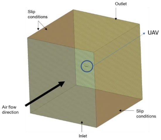
Figure 1.
Design space of CFD analysis for determining Cd and CL coefficients.
The mesh generated for the CFD analysis, as shown in Figure 2, was an unstructured mesh of tetras with 10 layers of hexas close to the UAV geometry. The purpose of this was to accurately capture the boundary layer phenomena close to the surface. The total size of the model was ~8,300,000 elements. The target of this analysis was to perform a quick analysis that will capture the basic phenomena around the UAV and provide a preliminary estimation of the loads on the UAV structure. For this reason, no complex turbulence models were used, other than the 1-equation Spallart-Almaras [28] turbulence model (a very robust model for aerospace and external aerodynamics applications). Furthermore, no sensitivity analysis was performed regarding the size and refinement of the mesh or the turbulence model (Figure 3).
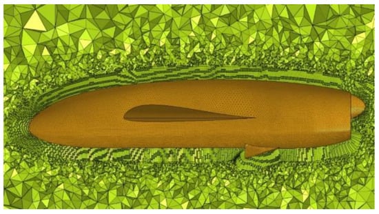
Figure 2.
Mesh discretization of the CFD analysis.
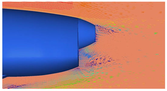
Figure 3.
Velocity streamlines at the rear of the UAV.
The CFD analysis revealed larger applied pressures at the tip of the aircraft and the edges of the wings, as expected. In addition, increased pressure was observed around the inlet of the aircraft. The pressure magnitude was approximately 1 atm, as indicated in Figure 4.
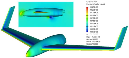
Figure 4.
Pressure distribution on the UAV.
To allow the validation of the CFD calculations while providing a simplified and accurate way to iterate and assess the loads, an analytical solution was developed. The latter facilitates the estimation of the pressure distribution along the wing based on several variables shown in Table 1. The calculation is based on Schrenk’s method [29], which is one of the most popular methods used to perform a preliminary analysis of wing loads, along with the Diederich method [30] and the Fourier series method. Schrenk’s method is relatively accurate when the lift distribution on the wing is close to the elliptical distribution. The lift distribution on the wing is analogous to the shape of the wing (as one of the main drivers of lift generation is the area of the wing); therefore, Schrenk’s method can be used with acceptable results on the unswept and untwisted wings of rectangular shape or trapezoidal shape, similar to the proposed wing design. In very simple and concise steps, the chord of the wing is calculated as an average of the actual chord and an elliptical one, and the wing is discretized in a number of sub-areas with the lift being calculated on each of these sub-areas. For the lift generated by the wing, the total weight of the aircraft is considered through the load factor n = L/W, and, in most cases, a safety factor is applied on top of those loads. The shear forces and bending moments are calculated along the wing in the same philosophy as in a typical shear/moment diagram calculation of a cantilever problem in statics theory. The presented procedure is efficient, accurate, and correlates well with the CFD analysis. The largest benefit is that, in the case of redesign and modifications, it instantaneously provides distributed pressures on the aircraft fuselage and wings, thus saving a great amount of computational time which would usually be required to set up a new CFD analysis. Also, it provides a very accurate and simple method to apply the distributed pressures onto the FEA models, through a polynomial equation. The final distribution of the pressure is depicted in Figure 5.

Table 1.
The variables required for the calculation of the distributed pressure along the wing of the aircraft.

Figure 5.
The (a) Section lift and (b) pressure distribution of the wing span (the red dashed line indicates a polynomial fit).
2.2. Topology Optimization
Due to the entailed challenges associated with the proposed problem, especially the extremely challenging weight limitations, optimization studies were initially conducted in order to define the optimum and critical structural paths, allowing for the most efficient design. For better understanding and to facilitate the thorough examination of the different areas, the studies conducted were distinguished in two steps as follows: (a) the fuselage optimization and (b) the wings optimization. Both analyses were based on topology optimization and, specifically, the “Level Set” methodology, using an initial design space, with inertia relief [30] being used to account for the lack of boundary conditions (BC), therefore presenting a more realistic structural representation of the aircraft in flight. In addition, the objective function (OF) was set to minimize the maximum stresses which appear on the vehicle under loading, with the overall weight being constrained to less than 20% of the initial mass of the design space. The material for this analysis was selected to be isotropic with engineering constants being close to those for solid aeronautic aluminum (Table 2). It is worth noting that all the optimization procedures utilized in this work, using the Altair Optistruct software, are gradient-based and either sequential quadratic programming (SQP) or dual optimizer programming based on separable convex approximation (DUAL) have been utilized, depending on the number of design variables (https://2021.help.altair.com/2021/hwsolvers/os/topics/solvers/os/gradient_based_opt_method_intro_c.htm (accessed on 6 March 2024)).

Table 2.
Homogenized material properties for the preliminary optimization analysis.
For the analysis of the fuselage, several load cases were used, such as equivalent wing loads and the weight of the drone in parked position and landing. The results are depicted in Figure 6. As expected, considering the color contour from blue to red, an excess of material is required around the housings of the wings and on the top and rear of the aircraft in order to maintain its structural integrity. The material concentration around the wing housing facilitated sturdy support conditions for the wings, as they simulated the boundary conditions of a cantilever beam. Furthermore, the prediction of material continuity on the top and rear of the drone was required as it kept the entire structure together. The wing housings acted as a shear web for the fuselage, as they bore the shear stresses developed by the wings at the fuselage sides and the bending moment, while the top and the rear parts deliver the loads arising by the weight of the fuselage and the aerodynamic loads.

Figure 6.
Critical material paths arising from body topology optimization analysis. The color bar indicates the importance of material presence from 0 to 1.
For the wings, where the pressure profile is qualitatively visualized in Figure 7, the same procedure was followed (Figure 8), with multiple load cases used, such as the distributed pressure (obtained from both the CFD and analytical studies presented in the previous section, Figure 5b) and the wings’ own weight. Finally, the boundary conditions used were as described above, through the use of the inertia relief computational technique.
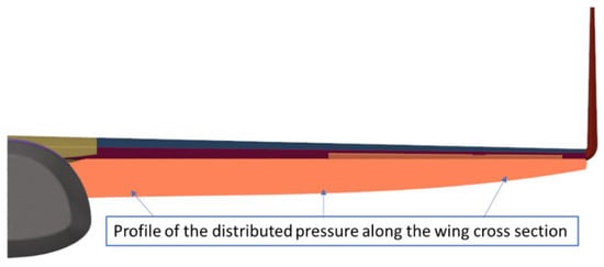
Figure 7.
Distributed pressure along the wing.
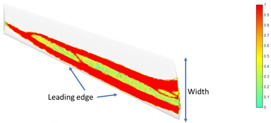
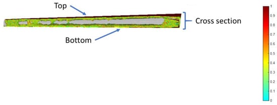
Figure 8.
Optimized material paths for the wing. The color bar indicates the importance of material presence from 0 to 1.
The results highlighted as critical regions were the top and bottom faces of the wing, located close to the leading edge and up to the middle of its width. In addition, excess material was required on the top and bottom through the thickness of the cross section, rendering the entire wing hollow.
3. Structural Design
This section is dedicated to the conceptual design of the main structural components of the UAV, following the design ideas and results discussed in the previous section. Initially, the assembly of the UAV is explained and analyzed. Furthermore, the components are looked into in depth, based on manufacturing considerations. Finally, the findings of composite optimization analysis and stress analysis will produce the outcome as to whether the proposed UAV design is feasible, considering manufacturing constraints as well as weight and stress limitations.
3.1. Full Assembly Design of the UAV
In this section the full assembly of the current drone design is demonstrated, and the structural components are listed (Table 3) and explained. In Figure 9, the preliminary structural design of the UAV is depicted. More specifically, the design philosophy is based on a large container (002), which will host the energy system, the electronics, and the first-person-view (FPV) camera. The latter will be jointed with the wings (003) through the 001 component, an intermediate structural and sturdy component. The 001 component is the main cap of the UAV. It protects the cargo, provides fast and easy access to the cargo holder for maintenance, and is connected to the wings and the cargo holder with bolts (006). The quick release cap (005) completes the aerodynamic shape of the UAV as this helps with fast refueling.

Table 3.
List of the structural components of the UAV.
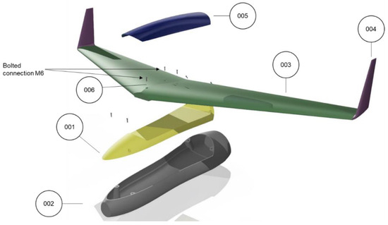
Figure 9.
Assembly of the Type C UAV.
Main cap—001
The main cap is a key structural component merging the wings and the cargo holder. More specifically, it is connected to the cargo holder with four M6 bolts, and it connected to the wings via three M6 bolts. This part contributes mainly to the structural integrity of the UAV, designed as a sandwich structure, and bears both the weight of the wings and the cargo holder through the bolt connections. Sandwich structures offer a very high bending stiffness/weight ratio, constituting a very good option in weight-sensitive applications.
Cargo holder—002
The cargo holder is the structural component containing and supporting all the mandatory apparatus for the drone operations, including electronics, the gas tank, fuel cells, batteries, the FPV camera, motors, and the landing system.
Wings—003
The wings are designed as a single unit component attached to the main cap. The wings are the main structural component responsible for bearing all flight loads, as well as for providing the aerodynamic lift. It should be noted that the wings are also responsible for connecting/supporting the vertical rotors and for transferring the loads through the whole structure, both in VTOL and normal flight mode.
Wing tips—004
The wing tips are responsible for the aerodynamic stability of the aircraft.
Quick release cap—005
The quick release cap contributes mostly to the aerodynamics of the UAV by fulfilling its aerodynamic shape. It is also expected to provide fast refueling access to the tank and hydrogen system.
Bolts and inserts—006
All bolted connections have been realized with the help of solid carbon patches (supporting and transmitting shear loads into the composite skin) and threaded inserts (keenserts) being inserted in the patches and skin during lamination. The low number of bolted connections would reduce the difficulties in the assembly of the whole UAV.
3.2. Material Selection and Manufacturing Considerations
In Figure 9, the conceptual design of the UAV is depicted. Several manufacturing considerations had to be considered in order to achieve both the desired weight limit (<9 kg) and the mandatory structural integrity. The manufacturing considerations include the following:
- Skin thickness on each structural component of the aircraft
- The skin lay-up on each structural component
- The distinction in regions entailing only composite laminates or sandwich laminates
- The composite ply thicknesses in each distinct laminate
For the time being, the materials used were picked based on (a) their physical properties; (b) their fracture properties; and, of course, (c) their density. The latter are distinguished in a UD carbon fiber composite material, a woven carbon fiber, and a polymeric foam used as the core material in selected areas. Their properties are shown in Table 4.

Table 4.
Material properties.
3.3. Composite Optimization
The optimization procedure is finalized with the composite optimization. The latter digs in the mechanics of composites, providing the optimum stack lay-up and the facilitation of composite manufacturing constraints. This is a two-step procedure. The first step provides general information regarding the composite lay-up thickness throughout the entire UAV. This is critical as it contributes to the redesign of the UAV. The second step optimizes the thickness and lay-up of each laminate separately, based on composite manufacturing constrains.
Free-size optimization
The procedure started with a free-size composite optimization analysis. The free-size optimization analysis facilitated the faster estimation of the entire UAV thickness. It also indicated which regions and which sandwich laminates of the UAV should entail only composite skin. Concerning the OF for this optimization study, the minimization of the overall stresses was set with the following constrains: (a) the mass to remain below 9 kg and (b) to maintain a symmetric lay-up throughout the thickness of the aircraft (a constraint that facilitates the manufacturability of each skin of the laminate). The loads input were as follows: (a) the final weight, namely 25 kg, (b) the distributed pressure calculated in Section 2.2 by hand calculations and CFD analysis, and finally (c) 3 g acceleration in all three directions (used separately). For optimization purposes (as a design space), the entire UAV structure was modelled as a single laminate, initially comprising several thick plies (super plies), one for each selected material, with different ply orientations. This procedure allows to identify the most appropriate plies in each area of the structure with their respective thicknesses. Figure 10 depicts the initial calculated values of the thickness laminates throughout the whole aircraft.

Figure 10.
Initial estimation of the thickness of the composite skin (left) and the foam core (right).
Size optimization
The second step differs from the first step in terms of manufacturing constrains and design space. In this analysis, we focus on the optimization of each distinct laminate configuration, based on the ply selection of the previous step. The goal is to derive an optimal laminate configuration with the correct ply thickness based on all manufacturing constraints. The total thickness of each laminate will be equal to the one predicted by the free-size optimization step. In Figure 11, the updated design with the partitioned sub-components is illustrated. For this second step of the composite optimization, that is, the size optimization analysis, the same loads were applied as in the free-size optimization. The OF again was set to minimize the resulting stresses of the structure. The mass was constrained not to exceed 9 kg, while for each laminate, symmetry conditions regarding the lay-up were applied. The difference between this and the first step is that for each composite ply, a specific thickness was constrained. The thickness of each ply was set as the input based on the fabrication process of each composite material. Consequently, the UD ply thickness was set to 0.125 mm and the woven carbon to 0.25 mm. The optimizer utilizes this input value and results in a manufacturable lay-up for each composite part.
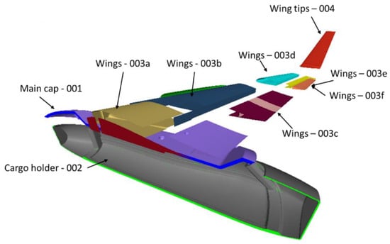
Figure 11.
Visualization of the UAV parts.
Following this step, the analytical design process presented in the next section was pursued, and the whole structure was partitioned into distinct thicknesses and components with ply transitions and shapes, taking into consideration both the manufacturability of the part and the aerospace standards.
4. Component Design
In this section, the final outcomes following the redesign of the structure and drone based on all the above studies are presented. Table 5 depicts all the parts of the aircraft and their respective weights.

Table 5.
Table of the weight of each component of the UAV.
Quick release cap—005
As already mentioned in Section 3.1, the quick release cap mostly contributes to the aerodynamics of the UAV (Figure 12). The laminate is comprised of woven carbon plies, and its total thickness is set 0.5 mm (Table 6).
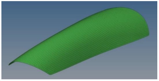
Figure 12.
Quick release cap.

Table 6.
Laminate properties of the 005 component.
Main cap—001
The main cap is located under the quick release cap, and is a structural component of the drone. It protects the hydrogen supply, the fuel cells, the batteries, the electronics, and the FPV camera. It is connected to the cargo body and contributes significantly to the aerodynamics of the UAV. It is comprised of a sandwich composite laminate which entails both composite and foam core plies (Table 7), as depicted in Figure 13 and Figure 14.

Table 7.
Laminate properties of the 001 component.
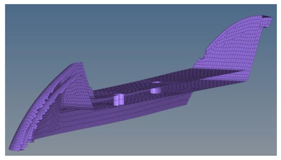
Figure 13.
Main cap—skin.
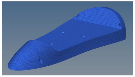
Figure 14.
Main cap—core.
Cargo holder—002
Inside the cargo holder, the fuel cells, the hydrogen system, the electronics, the batteries, and the FPV camera are located and supported. It is one of the main structural components of the drone, and the one the landing system is attached to. Similarly to the main cap, it is considered a key structural part, and is comprised of a sandwich composite laminate, as it is expected to anticipate greater loads than other parts. In Figure 15 and Figure 16, the skin and core of the sandwich laminate are depicted, and the material details are shown in Table 8.
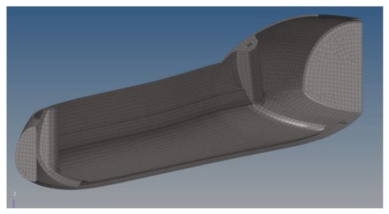
Figure 15.
Cargo holder—skin.
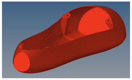
Figure 16.
Cargo holder—core.

Table 8.
Laminate properties of 002 component.
Inserts—006
The bolt holders are designed to be fabricated with solid carbon fiber (Figure 17). Their presence protects the main cap, the wings, and the cargo holder from excessive stresses arising from the bolt forces (tension, shear-out, etc.) and pre-tensioning.
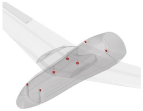
Figure 17.
Inserts.
Figure 18 depicts the modelling methodology used for the connection of two parts, e.g., the main cap with the cargo holder by the presence of the bolts. All the nodes of the holes in the purple and grey regions, respectively, are connected via two distinct rigid connections; the latter are termed RBE2 with a yellow and light blue font colors, respectively (Figure 18).
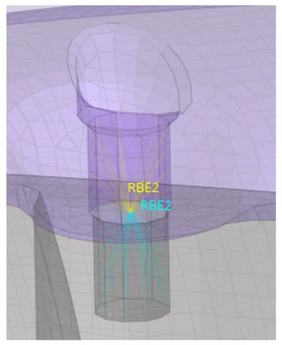
Figure 18.
Rigid body and c-bush connections simulating the pretention and presence of the bolts.
The two rigid bodies (RBE2 elements) are connected through a C-bush 0D connector. The C-bush is in fact a spring with six degrees of freedom (DoFs), three displacements, and three rotations, used here as full rigids, thus allowing the export of all forces into the bolted elements to be used later in the calculation and assessment of all connectors.
Wings—003a
The presented structural component of the wing section (central wing section) connects the whole wing component with the fuselage. This is a key structural part, bearing significant loads in all mission phases of the UAV, and acting as a support for the wings, withstanding both the aerodynamic loads in normal flight mode and the VTOL loads. It is essentially a sandwich structure with areas entailing only composite skin, as well as parts with both skin and foam cores (Table 9). Figure 19 presents the anatomy of part 003a, with Figure 19a presenting the composite skin, and Figure 19b showing the core internal part.

Table 9.
Laminate breakdown of the 003a wing component.

Figure 19.
Wing 003a component break down and description; (a): skin, (b): core.
Wings—003b and 003d
The main wing component is both a structural and aerodynamic component of the drone. It is a thin-walled sandwich structure, which incorporates both UD and woven composite fabrics. Specifically, it has been segregated into two separate laminates. The shear webs entail a cross-ply lamination (“0/90/Foam”) which is capable of bearing excessive shear loads and preventing the deformation of the foil shape during flight, while the top and bottom surfaces of the 003b part have been structured both with UD and woven fabrics in order to deal with greater bending loads, as shown in Table 10. Figure 20 presents the geometry of wing 003b and d parts, along with the respective laminates of the shear webs and the top and bottom surfaces.

Table 10.
Laminate breakdown of the wing 003b and 003d components.
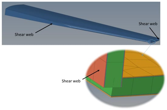
Figure 20.
Wing 003b and 003d component break down and analysis.
Wings—003c and 003e
These parts of the drone are attached to both wing components 003b and d and to the wing tip 004d part (Figure 21). They are responsible for holding the flaps while completing the airfoil shape of the wings. It is a thin carbon structure comprised of woven fabrics (Table 11). Its only structural requirement is to hold the flaps and flap mechanisms. On the other hand, it does not bear any significant loads, thus its small thickness is sufficient in keeping it sturdy.
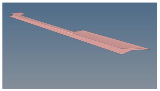
Figure 21.
Wing 003c and 003e components.

Table 11.
Laminate breakdown of the wing 003c and 003e components.
Wings—003f (flaps)
Through the motion of the flaps, the operator manages to steer the UAV (Figure 22). Therefore, the flaps ought to be able to withstand the aerodynamic loads, while maintaining their shape. Therefore, their laminate is comprised of three layers of woven fabric (Table 12).
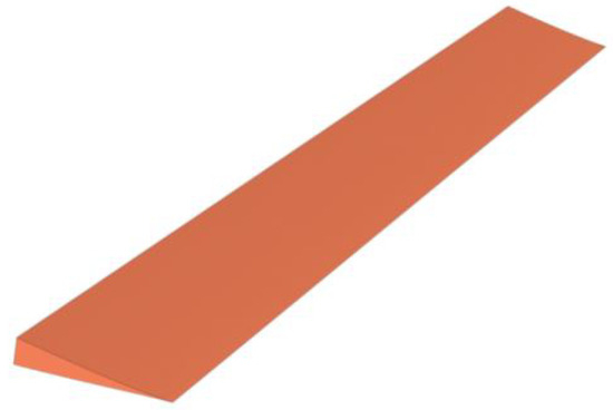
Figure 22.
Wing 003f component.

Table 12.
Laminate breakdown of the wing 003f component.
Wings tips—004
The wing tips (winglets) are responsible for the drone stabilization during normal flight operation (Figure 23). Their structure was designed as a sandwich structure (two layers filled with the core) in order to be able to maintain its structural rigidity against the aerodynamic loads. The core thickness is not mentioned in the below material as it is intended to fill the empty space between the skin lay-up (Table 13).
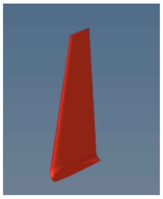
Figure 23.
Wing 004.

Table 13.
Laminate breakdown of the wing 004 component.
5. Stress Analysis
This section outlines the structural studies of the described design. Starting with the description of the modelling methodology, the stress analysis of the UAV is conducted and explained with all results and failure indices for each structural component. Furthermore, all analytical studies helping to assess the structural viability of the concept are presented, including the strength viability of the bolted connections. Also, it should be highlighted that a comparative case study is presented in the Appendix A in order to manifest the greater effectiveness of the proposed sandwich-structured design approach when compared to traditional spar–rib approaches that use stiffeners.
5.1. FE Model
In order to acquire accurate results, a fine FE mesh was created with an element size for discretization in the range of 5 to 10 mm, optimized for use with the OptiStruct solver, with an element failure (elements out of range based on structural criteria) of less than 1%. The mesh was unstructured, while it was entailing mostly triangle and pyramid elements (Figure 24).
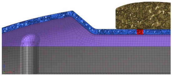
Figure 24.
Different element types used for the UAV discretization. While the different element colors indicate different compartments of the composite UAV.
Different element types were used for the discretization of the UAV. More specifically, in Table 14, the element types used for the discretization of each component are listed. In most parts, both shell and solid elements were used. For the skin parts, CTRIA3 shell elements for the triangles and CQUAD4 for the rectangles were used, while for the solid regions tetrahedrons, pyramids and pentas (https://altairuniversity.com/wp-content/uploads/2014/02/meshing.pdf (accessed on 6 March 2024)) with four, five, and six nodes, respectively, were used (Figure 25).

Table 14.
The respective element type used for the discretization of each component of the UAV.
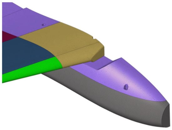
Figure 25.
FE mesh quality discretization of the UAV. Different colors indicate different compartments of the UAV.
Furthermore, great consideration was given to the lamination transition areas. Also, the artificial stress concentration had to be eliminated in regions where rigid connections were placed. The complexity of the problem, ranging from the anisotropy and inhomogeneity of the materials and the consideration of joints among the parts to the analysis itself, renders the mesh quality and FE discretization quite challenging. Taking into consideration all the above, a linear static analysis was performed for the estimation of critical stresses along the UAV shell. The composite failure criterion was set to be the maximum strain (Table 15), as this takes into account that the composite fails when the strain exceeds the respective allowance, making it a simple and direct way to predict the failure of composites [34].

Table 15.
Mathematical expression of the maximum strain criterion and failure strains of the involved materials.
In Table 15, and are the tensile and compressive failure strains along the fiber direction, and are the tensile and compressive failure strains vertically to the fiber direction, and is the shear failure strain [34].
5.2. Static Analysis
A static analysis was performed to determine the maximum stresses on the UAV components. The following load cases were used:
- Its own total weight (25 kg) during levitation
- The discretized pressure calculated in Section 2
- Acceleration loads of 3 g in all directions.
No boundary conditions were used, as the drone’s most critical stress state takes place during levitation. Therefore, in order to eliminate any singularity effects resulting from the lack of boundary conditions, the static analysis was solved using the inertia relief computational technique. Figure 26 depicts the predicted displacement field. It is observed that the maximum displacement occurs at the tip of the wing tip 004 component. Vertical displacements of 7mm were observed. As will be further presented, no critical amount of stresses are developed in the structural components of the UAV. The aforementioned statement occurs taking into consideration the displacement prediction. The predicted displacement of 7 mm considering a 1500 mm wingspan is within the allowed limits, as it is permitted for the deflection to be 5% of the semi-wing span [34], which, in our case, is 0.05%.
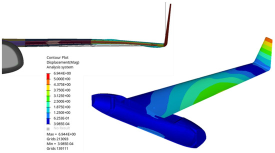
Figure 26.
Predicted displacement field.
5.3. Failure Index
The composite failure indices for most critical parts are presented hereafter. A safety factor (SF) of 2 was selected and therefore failure indices above 0.5 should be eliminated. A general rule for the safety index estimation is to derive the internal resulting stresses during loading from the materials strength. For our case though, a strain-based failure criterion was used, as already mentioned. In Figure 27 the failure index of the UAV is again presented, with the threshold of the results lowered to the maximum value for better visualization. The target is to demonstrate the regions of the structure that develop the higher stresses. Those are the regions inside the red circles. Regions (1) and (2) are located around the bolted connections and therefore transmit an amount of the developed force to the structure. Region (3) is on the mid-bottom of the wing, an area of transition from a thick to a thinner cross section, therefore some stress concentration is justified there. Region (4) is another minor stress concentration region around connections, However, significantly lower than the structural limits.

Figure 27.
Failure index for the entire UAV—lowered threshold.
5.4. Maximum Stresses and Safety Factor
Figure 28 and Figure 29 depict the maximum stresses which occurred during the loading of the aircraft. For the skin, the maximum stresses reached up to 50 MPa, while for the foam, this was less than <1 MPa. This provides a uniform stress distribution on the structure, as the strain variation is almost 50 MPa, far from causing any structural damage to the UAV. In addition, the safety factor of each material is presented. For the skin (carbon laminate), the SF is over 5, while for the foam, this is over 4, indicating that the strength of each material is five and four times higher than the developed stresses within each material, respectively.
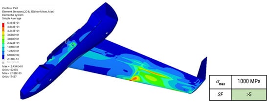
Figure 28.
Element stresses—Composite skin (left) and safety factor (right).

Figure 29.
Element stresses—foam (left) and safety factor (right).
5.5. Bolted Connections
Within the design of the UAV, we tried to keep the number of bolts (Figure 30 and Figure 31) as low as possible in order to avoid stress concentrations, but also to limit the design complexity and reduce the assembly/disassembly time. Figure 31 depicts all the bolts along with their connections to the UAV parts.
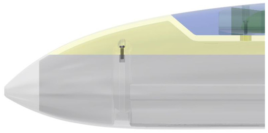
Figure 30.
Size view of the UAV and the connection between the main cap and cargo holder.
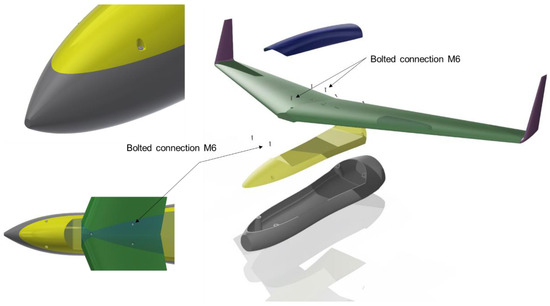
Figure 31.
Bolts and connections between parts.
Numerical bolt calculations were conducted to check the viability of all bolted connections together with their affecting parameters, such as bolt types, grades, pretension, etc. Table 16 lists the loads on each bolt (as retrieved from the analysis conducted) together with the resultants and the safety factors computed analytically for each connection. It is shown that the maximum shear load reported within the bolts is approximately 154 N, while the maximum load in tension is 53 N. The aforementioned values are far from the bolts’ limits, which are 10,400 N. (Table 16, Figure 32).

Table 16.
Bolt numbering and location.
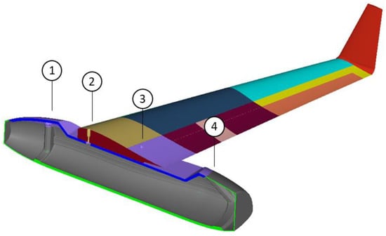
Figure 32.
Bolts numbering based on Table 16.
6. Discussion
Due to the multi-disciplinary character of this work, a lot of issues can be proposed and remarked. When it comes to dynamic loading like gusts or shock loads, it should be highlighted that the structural design was performed considering 3 g acceleration in all three directions, namely, a 750 N load in every direction, and 90 kPa pressure on top of the entire aircraft, for a velocity magnitude of 33 m/s. Considering that the missions of the UAV will take place in up to 10 m/s wind and an acceptable gust will potentially rise up to 20 m/s, the structural integrity of the UAV will withhold this. Also, regarding the manufacturing of the UAV and the subsequent environmental impact, it should be emphasized that the present design is quite flexible in terms of fabrication processes. Even if the study was performed with autoclave-based thermosets, the fabrication process would be performed either by resin infusion or out-of-autoclave prepregs. The first method would be easily utilized in bio-based resins, while, by employing the second method, the environmental impact is drastically reduced due to the absence of an autoclave furnace. In addition, concerning the usage of 3D-printed thermoplastics, in this UAV, the winglets, the flaps, and the quick release cap would be easily replaced by 3D-printed materials. The remaining parts are considered structural parts, and, without a reinforcement, they may not withstand the calculated forces, especially after many missions. Considering the scalability of the present UAV, by employing a liquid resin infusion, the scale-up process would be applicable (i.e., fabrication of large wind turbine blades). In terms of structural analysis, the scalability would pose several challenges, especially in the joint parts. However, taking into account the attained weight reduction achieved by the proposed methodology, critical points would be easily reinforced through increasing the composite’s thickness.
7. Conclusions
The present work gives an insight into the design process of a type C composite UAV, demonstrating all studies conducted to assess its viability. To reach a final design concept that covers all requirements, several complementing steps were performed. Initially, aerodynamic studies were carried out to determine and understand the loads subjected onto the UAV in different missions/scenarios. A comprehensive CFD analysis was executed, the findings of which were validated and enhanced with an analytical solution aiming to eliminate the discrepancies of pressure distributions along the aircraft between the two solutions. Consequently, topology optimization analysis was performed both on the body and the wings in order to determine the optimum material paths and establish a basis for the conceptual preliminary structural design. Composite optimization studies were also conducted, aiming to determine the minimum and maximum laminate thicknesses throughout the UAV, following both mass and ply thickness constraint rules. All these studies were needed to perform a structural design of the full drone assembly, which was then used for thorough structural examination via static analysis. The low stresses developed both in the composite fabrics and the foam core highlight the feasibility of the design, suggesting a successful design approach that will lead to the final detailed design of the drone.
Conclusively, the proposed road map for the optimization-based UAV design consists of the following steps:
- Aerodynamic analysis for the estimation of loads.
- Topology optimization to determine the material paths of the initial design.
- Free-size optimization to obtain the first estimation of the thicknesses of each material configuration.
- Size/Composite optimization to fully determine the thicknesses and lay-ups of each material region.
- Static and stress analysis to ensure the safe and successful UAV design.
The aforementioned design procedure is easily applicable to any type, size, and configuration of UAV since the whole design process is optimization based. Furthermore, the manufacturing constraints applied during the optimization procedures enhance the manufacturability of the proposed UAV. For future work, the incorporation of composite spring leaf landing gear and the utilization of different materials, such as high-performance 3D-printed thermoplastics, could be highly interesting focuses of future studies. Another compelling research direction could be towards the manufacturing processes and possible challenges of the proposed UAV.
Author Contributions
Conceptualization, C.S.R. and N.A.C.; methodology, C.S.R. and N.A.C.; software, C.S.R.; validation, C.S.R., N.A.C. and D.K.D.; investigation, C.S.R. and D.K.D.; writing—original draft preparation, C.S.R. and D.K.D.; writing—review and editing, C.S.R., D.K.D. and N.A.C.; All authors have read and agreed to the published version of the manuscript.
Funding
This research received no external funding.
Data Availability Statement
The data can be available by reaching the authors through the email provided for correspondence.
Acknowledgments
The publication fees of this manuscript have been financed by the Research Council of the University of Patras.
Conflicts of Interest
The authors declare no conflicts of interest.
Appendix A
A comparative case study for the design philosophy of an aerostructure has been performed. Two different approaches have been simulated and compared as follows: (a) the proposed design of a sandwich-structured UAV body with a lay-up of ([0/90]4S/)S, and a 2 mm thickness for each face sheet and a 10 mm thickness for the foam core, and (b) the traditional spar–rib approach with I-Beam stiffeners. The airfoil is 4 mm thick with a lay-up of [0/90]8S, and the lamination for the I-Beams is [0/90]6S, with a 3 mm thickness for the vertical parts. These two different structures are excited by a distributed pressure of 10 kPa at their top surface and are clamped at their back edges. Both the structures are 1 m long, and the materials used for the UD composite and the foam core are the same as in Table 4. Their cross-sections are shown in Figure A1.
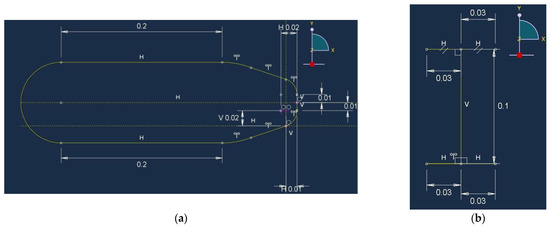
Figure A1.
Drawings of the comparative study wing part (a) airfoil cross section and (b) the I-Beam geometry.
In the following figures (Figure A2, Figure A3, Figure A4, Figure A5, Figure A6 and Figure A7), the contour plots of displacements and stresses in the Z and X axes, respectively, are illustrated.
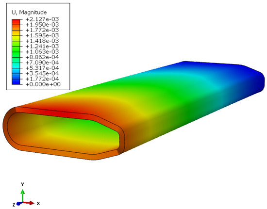
Figure A2.
Contour of displacement magnitude for the sandwich-structured airfoil.
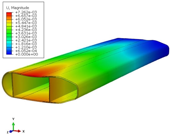
Figure A3.
Contour of displacement magnitude for airfoil with I-Beam stiffeners.
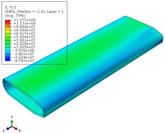
Figure A4.
Contour of stresses in the longitudinal direction (Z) for the sandwich-structured airfoil.
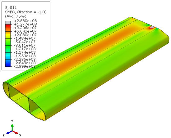
Figure A5.
Contour of stresses in the longitudinal direction (Z) for airfoil with I-Beam stiffeners.
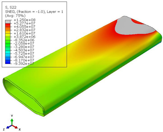
Figure A6.
Contour of stresses in the transverse direction (X) for the sandwich-structured airfoil.
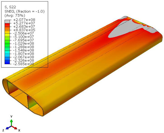
Figure A7.
Contour of stresses in the transverse direction (X) for airfoil with I-Beam stiffeners.
The differences between the two simulations are summarized in Table A1. In this table, the values and percentage decreases of important quantities evince the higher efficiency of the proposed sandwich-structured design when compared to the traditional stiffener design approach.

Table A1.
Comparison of the two design approaches.
Table A1.
Comparison of the two design approaches.
| Value under Investigation | Airfoil with Sandwich Structure Cross Section | Airfoil with I-Beam Stiffeners | Percentage Decrease [%] |
|---|---|---|---|
| Max. Displacement (mm) | 2.127 | 7.262 | 70.7 |
| Max. Relative Displacement of top and bottom surface (mm) | 0.15 mm | 1.2 mm | 87.5 |
| Max Stress along fibers (MPa) | 128 | 288 | 55.6 |
| Max Stress normal to fibers (MPa) | 125 | 207 | 39.6 |
| Mass (kg) | 5.18 | 7.77 | 33.3 |
References
- Sobieszczanski-Sobieski, J.; Haftka, R.T. Multidisciplinary Aerospace Design Optimization: Survey of Recent Developments. Struct. Optim. 1997, 14, 1–23. [Google Scholar] [CrossRef]
- Bartholomew, P. The Role of MDO within Aerospace Design and Progress towards an MDO Capability. In Proceedings of the 7th AIAA/USAF/NASA/ISSMO Symposium on Multidisciplinary Analysis and Optimization, St. Louis, MO, USA, 2–4 September 1998; American Institute of Aeronautics and Astronautics: Reston, VA, USA, 1998; pp. 2157–2165. [Google Scholar]
- Kroo, I.; Kroo, I. Multidisciplinary Optimization Applications in Preliminary Design—Status and Directions. In Proceedings of the 38th Structures, Structural Dynamics, and Materials Conference, Kissimmee, FL, USA, 7–10 April 1997; American Institute of Aeronautics and Astronautics: Reston, VA, USA, 1997. [Google Scholar]
- Sóbester, A.; Keane, A.J. Multidisciplinary Design Optimization of UAV Airframes. In Proceedings of the Collection of Technical Papers—AIAA/ASME/ASCE/AHS/ASC Structures, Structural Dynamics and Materials Conference, Newport, RI, USA, 1–4 May 2006; American Institute of Aeronautics and Astronautics: Reston, VA, USA, 2006; Volume 1, pp. 136–148. [Google Scholar]
- Rajagopal, S.; Ganguli, R.; Pillai, A.C.R.; Lurdharaj, A. Conceptual Design of Medium Altitude Long Endurance UAV Using Multi Objective Genetic Algorithm. In Proceedings of the Collection of Technical Papers—AIAA/ASME/ASCE/AHS/ASC Structures, Structural Dynamics and Materials Conference, Honolulu, HI, USA, 23–26 April 2007; American Institute of Aeronautics and Astronautics: Reston, VA, USA, 2007; Volume 3, pp. 2225–2237. [Google Scholar]
- Grossman, B.; Haftka, R.T.; Kao, P.J.; Polen, D.M.; Rais-Rohani, M.; Sobieszczanski-Sobieski, J. Integrated Aerodynamic-Structural Design of a Transport Wing. J. Aircr. 1990, 27, 1050–1056. [Google Scholar] [CrossRef]
- Dovi, A.R.; Wrenn, G.A. Aircraft Design for Mission Performance Using Nonlinear Multiobjective Optimization Methods. J. Aircr. 1990, 27, 1043–1049. [Google Scholar] [CrossRef]
- Wakayama, S.; Kroo, I. Subsonic Wing Planform Design Using Multidisciplinary Optimization. J. Aircr. 1995, 32, 746–753. [Google Scholar] [CrossRef]
- Martins, J.R.R.A.; Alonso, J.J.; Reuther, J.J. Complete Configuration Aero-Structural Optimization Using a Coupled Sensitivity Analysis Method. In Proceedings of the 9th AIAA/ISSMO Symposium on Multidisciplinary Analysis and Optimization, Atlanta, GA, USA, 4–6 September 2002; American Institute of Aeronautics and Astronautics: Reston, VA, USA, 2002. [Google Scholar]
- Carrier, G. Multi-Disciplinary Optimisation of a Supersonic Transport Aircraft Wing Planform. In Proceedings of the ECCOMAS 2004—European Congress on Computational Methods in Applied Sciences and Engineering, Jyväskylä, Finland, 24–28 July 2004. [Google Scholar]
- Kumano, T.; Jeong, S.; Obayashi, S.; Ito, Y.; Hatanaka, K.; Morino, H. Multidisciplinary Design Optimization of Wing Shape for a Small Jet Aircraft Using Kriging Model. In Proceedings of the Collection of Technical Papers—44th AIAA Aerospace Sciences Meeting, Reno, NV, USA, 9–12 January 2006; American Institute of Aeronautics and Astronautics: Reston, VA, USA, 2006; Volume 15, pp. 11158–11170. [Google Scholar]
- Kim, Y.; Jeon, Y.H.; Lee, D.H. Multi-Objective and Multidisciplinary Design Optimization of Supersonic Fighter Wing. J. Aircr. 2006, 43, 817–824. [Google Scholar] [CrossRef]
- Kafkas, A.; Kilimtzidis, S.; Kotzakolios, A.; Kostopoulos, V.; Lampeas, G. Multi-Fidelity Optimization of a Composite Airliner Wing Subject to Structural and Aeroelastic Constraints. Aerospace 2021, 8, 398. [Google Scholar] [CrossRef]
- Kilimtzidis, S.; Kotzakolios, A.; Kostopoulos, V. Efficient Structural Optimisation of Composite Materials Aircraft Wings. Compos. Struct. 2023, 303, 116268. [Google Scholar] [CrossRef]
- Imumbhon, J.O.; Alam, M.D.; Cao, Y. Design and Structural Analyses of a Reciprocating S1223 High-Lift Wing for an RA-Driven VTOL UAV. Aerospace 2021, 8, 214. [Google Scholar] [CrossRef]
- Bartoli, N.; Lefebvre, T.; Dubreuil, S.; Olivanti, R.; Priem, R.; Bons, N.; Martins, J.R.R.A.; Morlier, J. Adaptive Modeling Strategy for Constrained Global Optimization with Application to Aerodynamic Wing Design. Aerosp. Sci. Technol. 2019, 90, 85–102. [Google Scholar] [CrossRef]
- Raja Sekar, K.; Ramesh, M.; Naveen, R.; Prasath, M.S.; Vigneshmoorthy, D. Aerodynamic Design and Structural Optimization of a Wing for an Unmanned Aerial Vehicle (UAV). IOP Conf. Ser. Mater. Sci. Eng. 2020, 764, 012058. [Google Scholar] [CrossRef]
- Hutagalung, M.R.A.; Latif, A.A.; Israr, H.A. Structural Design of Uav Semi-Monoque Composite Wing. J. Transp. Syst. Eng. 2016, 3, 26–34. [Google Scholar]
- Blair, M.C.; Takahashi, T.T. Optimal Composite Structural Design of Unmanned Aerial System Wings. In Proceedings of the AIAA AVIATION 2022 Forum, Chicago, IL, USA, 27 June–1 July 2022; pp. 1–25. [Google Scholar] [CrossRef]
- Gonzalez, L.F.; Lee, D.S.; Srinivas, K.; Wong, K.C. Single and Multi-Objective UAV Aerofoil Optimisation via Hierarchical Asynchronous Parallel Evolutionary Algorithm. Aeronaut. J. 2006, 110, 659–672. [Google Scholar] [CrossRef][Green Version]
- Gonzalez, L.F.; Périaux, J.; Srinivas, K.; Whitney, E.J. A Generic Framework for the Design Optimisation of Multidisciplinary UAV Intelligent Systems Using Evolutionary Computing. In Proceedings of the 44th AIAA Aerospace Sciences Meeting and Exhibit, Reno, NV, USA, 9–12 January 2006; Volume 23, pp. 17673–17691. [Google Scholar] [CrossRef]
- Rajagopal, S.; Ganguli, R. Multidisciplinary Design Optimization of a Uav Wing Using Kriging Based Multi-Objective Genetic Algorithm. In Proceedings of the 50th AIAA/ASME/ASCE/AHS/ASC Structures, Structural Dynamics, and Materials Conference, Palm Springs, CA, USA, 4–7 May 2009. [Google Scholar] [CrossRef]
- Rayed, A.M.; Esakki, B.; Ponnambalam, A.; Banik, S.C.; Aly, K. Optimization of UAV Structure and Evaluation of Vibrational and Fatigue Characteristics through Simulation Studies. Int. J. Simul. Multidiscip. Des. Optim. 2021, 12, 17. [Google Scholar] [CrossRef]
- Aswin Kumar, V.; Sivaguru, M.; Rohini Janaki, B.; Sumanth Eswar, K.S.; Kiran, P.; Vijayanandh, R. Structural Optimization of Frame of the Multi-Rotor Unmanned Aerial Vehicle through Computational Structural Analysis. J. Phys. Conf. Ser. 2021, 1849, 012004. [Google Scholar] [CrossRef]
- Martínez, X.; Pons-Prats, J.; Turon, F.; Coma, M.; Barbu, L.G.; Bugeda, G. Multi-Objective Multi-Scale Optimization of Composite Structures, Application to an Aircraft Overhead Locker Made with Bio-Composites. Mathematics 2023, 11, 165. [Google Scholar] [CrossRef]
- David, E. Goldberg Genetic Algorithms in Search, Optimization, and Machine Learning; Addison-Wesley: Boston, MA, USA, 1989; Volume 27, ISBN 0201157675. [Google Scholar]
- Srinivas, N.; Deb, K. Muiltiobjective Optimization Using Nondominated Sorting in Genetic Algorithms. Evol. Comput. 1994, 2, 221–248. [Google Scholar] [CrossRef]
- Zienkiewicz, O.; Taylor, R.; Zhu, J. Turbulent Flows. In The Finite Element Method Set; Elsevier: Amsterdam, The Netherlands, 2005; pp. 248–273. [Google Scholar]
- Kamal, N.N.M.; Basri, A.A.; Basri, E.I.; Basri, I.S.; Abas, M.F. Comparison Study between Schrenk’s Approximation Method and Computational Fluid Dynamics of Aerodynamic Loading on UAV NACA 4415 Wing. J. Adv. Res. Fluid Mech. Therm. Sci. 2019, 64, 283–292. [Google Scholar]
- Gurdal, Z. Design and Optimization of Laminated Composite Materials; Harvard Dataverse: Hoboken, NJ, USA, 2006; Volume 1999, ISBN 047125276X. [Google Scholar]
- Siorikis, D.K.; Rekatsinas, C.S.; Christoforou, A.P.; Saravanos, D.A. Experimental and Numerical Investigation of Contact Laws for the Rapid Simulation of Low-Energy Impacts on Laminated Composite Plates. Compos. Struct. 2017, 168, 646–656. [Google Scholar] [CrossRef]
- Siorikis, D.K.; Nastos, C.V.; Chrysochoidis, N.A.; Theodosiou, T.C.; Rekatsinas, C.S.; Saravanos, D.A.; Codines, C.; Abdi, F.; Martino Gonzalez, E. Experimental and Micromechanics-Based Numerical Analysis of High-Velocity Impact on Laminated Composite Plates. In Proceedings of the ECCM18—18th European Conference on Composite Materials, Athens, Greece, 24–28 June 2018; pp. 24–28. [Google Scholar]
- Rekatsinas, C.S.; Siorikis, D.K.; Christoforou, A.P.; Saravanos, D.A. A Non-Linear Cubic Spline Layerwise Time Domain Spectral Finite Element for the Analysis of Impacts on Sandwich Structures. Compos. Struct. 2021, 260, 113531. [Google Scholar] [CrossRef]
- Li, S. The Maximum Stress Failure Criterion and the Maximum Strain Failure Criterion: Their Unification and Rationalization. J. Compos. Sci. 2020, 4, 157. [Google Scholar] [CrossRef]
Disclaimer/Publisher’s Note: The statements, opinions and data contained in all publications are solely those of the individual author(s) and contributor(s) and not of MDPI and/or the editor(s). MDPI and/or the editor(s) disclaim responsibility for any injury to people or property resulting from any ideas, methods, instructions or products referred to in the content. |
© 2024 by the authors. Licensee MDPI, Basel, Switzerland. This article is an open access article distributed under the terms and conditions of the Creative Commons Attribution (CC BY) license (https://creativecommons.org/licenses/by/4.0/).