Article

Conjunction Analysis Software Suite for Space Surveillance and Tracking

by
Sergio Bonaccorsi
1,†,
Marco Felice Montaruli
1,*,†,
Pierluigi Di Lizia
1,
Moreno Peroni
2,
Alessandro Panico
2,
Marco Rigamonti
2 and
Francesco Del Prete
2
1
Department of Aerospace Science and Technology, Politecnico di Milano, Via La Masa 34, 20156 Milan, Italy
2
Flight Test Department of the Italian Air Force, Via Pratica di Mare 45, Pomezia, 00071 Rome, Italy
*
Author to whom correspondence should be addressed.
These authors contributed equally to this work.
Aerospace 2024, 11(2), 122; https://doi.org/10.3390/aerospace11020122
Submission received: 9 November 2023 / Revised: 24 January 2024 / Accepted: 25 January 2024 / Published: 31 January 2024
(This article belongs to the Section Astronautics & Space Science)

Abstract

:
The increasing number of objects in Earth orbit has encouraged the development of space surveillance and tracking (SST) applications. A critical aspect of SST is the identification and characterization of close encounters between pairs of space objects. The present work introduces a tool for the analysis of conjunctions, consisting of several modules. The first module, which has been shown to greatly speed up the process, employs a series of geometric and temporal filters to shorten the list of potential colliding pairs. The remaining objects are then propagated to compute important parameters such as time of closest approach (TCA), miss distance (MD), and probability of collision (PoC), the latter using three different methods. When a conjunction assessment returns an MD or a PoC that exceeds predefined alert thresholds, the algorithm enables the planning of an impulsive collision avoidance maneuver (CAM) at specific maneuver epochs. CAM candidates are determined using an analytical Keplerian approach, with the goal of achieving the desired PoC or MD. The user can then verify the performance of a specific candidate through perturbed propagation, and the MD and PoC are recalculated after the maneuver to ensure that they meet the desired thresholds. In conclusion, this paper evaluates the performance of the tool using synthetic and real data, providing valuable insights into its effectiveness.

1. Introduction

In the last few decades, space debris, including inactive satellites, rocket bodies, and fragments of various sizes, has emerged as a global challenge for space agencies and institutions, thus becoming a major concern. The two orbit regions most densely populated by space objects are the low earth orbit (LEO) and the geostationary orbit (GEO). Notably, the majority of objects in orbit are space debris, while cooperative satellites make up only a small fraction [1].
The presence of space debris poses a substantial threat to space operations. Potential collisions with space debris can result in a range of consequences, from gradual erosion of satellite surfaces to the complete destruction of active satellites. Such collisions can also lead to the creation of thousands of additional fragments, contributing to environmental problems and the risk of cascade effects [2].
To ensure the safety of space operations, space agencies and organizations worldwide have implemented various strategies. Moreover, international cooperation is actively underway in the field of space surveillance and tracking (SST). In Europe, two noteworthy programs address this issue: the European Space Agency (ESA) Space Situational Awareness (SSA) Programme [3] and the European Union Space Surveillance and Tracking (EUSST) Framework [4]. EUSST is a collaborative consortium involving European national agencies and institutions, and it is responsible for providing essential services such as conjunction analysis [5], fragmentation analysis [6,7], and re-entry prediction [8]. These services rely on data collected from ground-based sensors, including optical telescopes (offering precise angular data) [9], radars (providing both angles and range or Doppler shift measurements) [10], and lasers (supplying exceptionally accurate range measurements) [11]. In particular, survey radars play a critical role in characterizing the orbits of unidentified objects upon their initial detection [12,13,14]. In addition to the above-mentioned services, a crucial role is played by maneuver detection [15] and proximity operations monitoring [16,17]. The latter is expected to become more and more fundamental in the future for the active debris removal programs.
Italy’s participation in the EUSST program involves three entities: the Italian Space Agency (ASI), the Astrophysics National Institute (INAF), and the Italian Ministry Of Defence, with the Italian Air Force (AM) largely involved. Italy’s specific role within this program pertains to re-entry and fragmentation services. To effectively manage the vast amount of observational data, there is a need for the development of efficient and reliable tools. In this context, the Flight Test Department of the Italian Air Force is responsible for establishing a system architecture which collects and processes data to provide SSA services to both military and civilian users, as well as to the EUSST consortium. The system, named the ISOC Suite after the Italian SST Operational Centre (ISOC) of the Italian Air Force, has been meticulously designed with a web-based infrastructure, where space objects and associated data populate a catalog [18]. The ISOC Suite provides SST services and functions which work in unison to enhance awareness of space events in Earth-centered orbits. The embedded software is the result of a collaborative effort with national industry and academia, designed and implemented with a focus on operational requirements.
As mentioned above, the collision avoidance service is crucial for space traffic management, and it is tasked with assessing potential conjunctions among cataloged objects. When a conjunction is detected, a conjunction data message (CDM) [19] is generated, consolidating information about the involved satellites. Typically, these objects are categorized as primary (typically maneuverable satellites) and secondary (either operational or inactive satellites), composing a pair [20]. The CDM includes information on the Cartesian state of these satellites, both in terms of mean and covariance, the time of closest approach (TCA), the associated miss distance (MD), representing the distance at the closest approach, and the probability of collision (PoC).
This work presents the prototype of the conjunction analysis tool developed for the ISOC Suite, a collaborative effort involving the Italian Air Force, Leonardo Company (Rome, Italy), and Politecnico di Milano. The development of this tool was conducted to meet the tailored requirements, satisfying very specific needs. The software architecture prioritizes optimal computational performance, and comprises three main modules, each dedicated to the precise identification and characterization of potential conjunction events. The initial module employs a filtering sequence to screen out pairs that fail to meet specific criteria, thus narrowing down the candidates. Subsequently, the remaining events are more meticulously characterized through the calculation of critical parameters (including the metrics mentioned above), and the user can choose to store information for relevant events and generate output files, such as the CDM, adhering to the standard format set by the Consultative Committee for Space Data Systems (CCSDS). In addition, based on the user requirements, the tool offers the possibility to compute a collision avoidance maneuver (CAM), providing operators with a potential means to avoid collisions. Overall, the tool can manage input files like the CDM, two-line elements (TLEs), Orbit Ephemeris Message (OEM), and Orbit Parameter Message (OPM).
The paper structure is as follows. The ISOC Suite and the PoC computation methodology are presented in Section 2 and Section 3, respectively. Then, the algorithmic flow is illustrated in Section 4 and Section 5. Subsequently, the tool validation is presented in Section 6 and, finally, the algorithm performance is evaluated through real-case operational scenarios in Section 7.

2. Italian SST Operations Centre

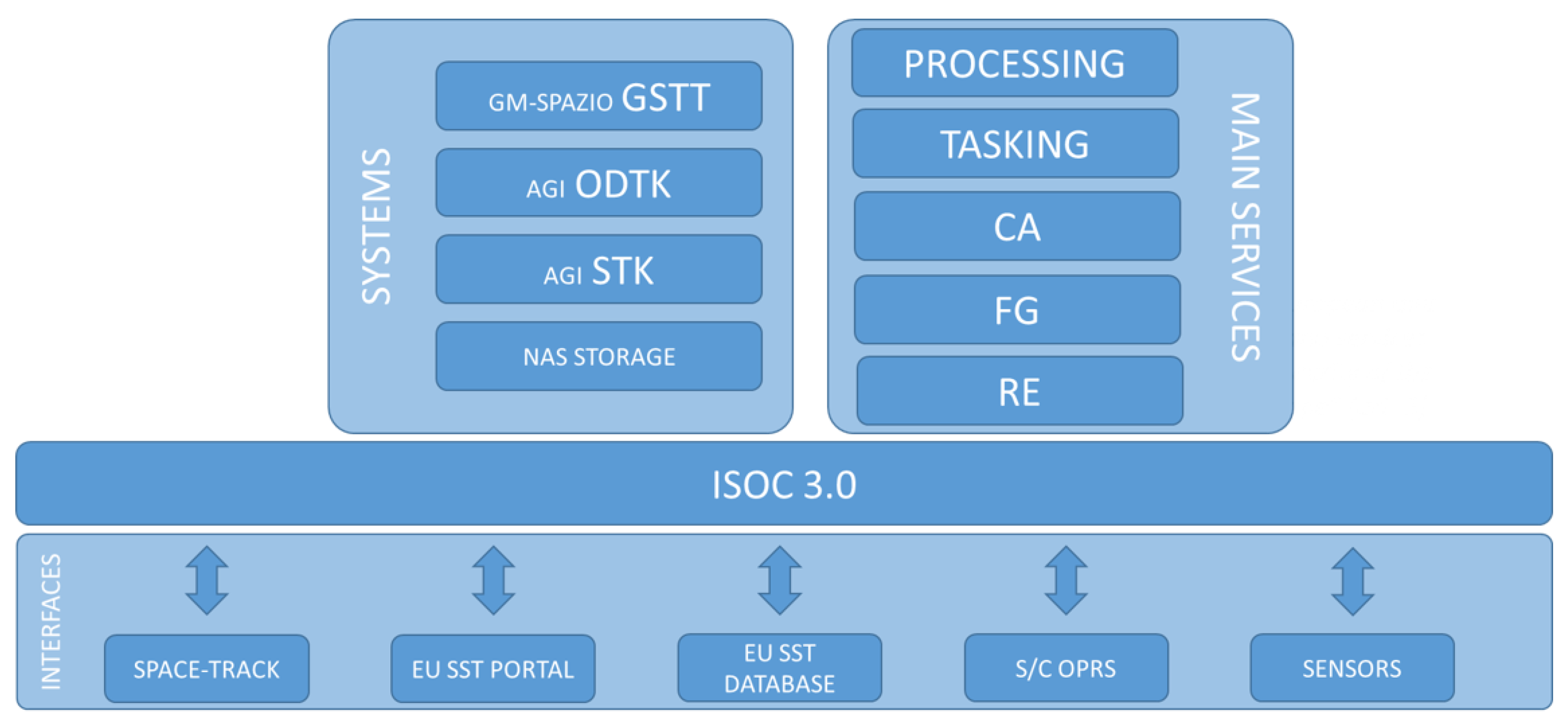
The ISOC was originally established in 2014 and operated by the military personnel of the Flight Test Department of the Italian Air Force. Currently, the operational activities are led by the the Space Situational Awareness Centre (C-SSA), whereas the Flight Test Department is responsible for research and development operations. The ISOC Suite is a complex system that was originally developed to support SST tasks, but it is currently evolving towards a broader awareness of the space scenario, to enhance the national security for both civil and military applications. The ISOC is also included in the EUSST framework, supporting the services listed below:
  • Re-entry (RE): primarily responsible for the analysis of uncontrolled re-entry into the low atmosphere for large and dangerous objects.
  • Fragmentation (FG): primarily responsible for the analysis of in-orbit fragmentation as a consequence of satellite break-ups or collisions.
  • Collision avoidance (CA): cold redundant operational center for the analysis of the collision probability and geometry for conjunction events.
The ISOC Suite is used to support the above-mentioned services, whose high level architecture is represented in Figure 1. The main inputs of the suite are provided by national sensors, consortium observations, and the European observation catalog, along with available public sources. The inner part of the system is also able to use commercial off-the-shelf (COTS) and proprietary software. The system’s outputs are the services shown in the right part of Figure 1. A functional part of the entire system is the collision avoidance service, that could be guaranteed by the suite described in this document.

3. Probability of Collision

To accurately deal with the uncertainty linked to the orbital state of a tracked satellite, it is crucial to determine the alert level in satellite conjunctions through a stochastic description. As a result, the PoC becomes a pivotal parameter in the operational management of the CA service. In the present suite, the PoC computation is conducted in the one-to-one analysis, as better discussed in Section 4.2.
Let us consider the relative position r between a primary and a secondary. Associating a diameter to the involved objects’ geometry, through the definition of D p and D s for the primary and the secondary objects, respectively, it is possible to define the hard body radius: HBR = D p + D s / 2 . From a conceptual point of view, a collision occurs when | r | HBR and, to compute the associated PoC, two models exist, depending on the conjunction features:
  • The short-term encounter model [21] is designed for conjunctions featuring a high relative velocity between the objects at the TCA. It is particularly well-suited for LEO encounters. This model operates under the assumption of constant position uncertainties during the conjunction and employs a deterministic approach for describing velocities [20].
  • The long-term encounter model [22] is designed for conjunctions with a minimal relative velocity between the involved objects. In these scenarios, the objects spend a substantial amount of time in close proximity, and the encounters may occur multiple times per orbit. This model is particularly applicable to GEO encounters, formation flying, and proximity operations.
In the present study, the focus is placed on the short-term encounter model due to its advanced state of development. This model assumptions facilitate the definition of an encounter frame, commonly referred to as the B-plane, at the TCA. The precise formulation of the B-plane may vary among authors, but it consistently exhibits two key characteristics: it is centered on the mean-position center of gravity of one of the two objects, and is oriented orthogonally to the direction of the relative velocity.
Based on the assumptions of the short-term model, it becomes feasible to simplify the problem into a two-dimensional space, thus obtaining the integral in Equation (1), which is a compact version of the one in [23].
PoC = 1 ( 2 π ) det Σ 2 D exp 1 2 r μ 2 D T Σ 2 D 1 r μ 2 D d r
This reduces the computation of the PoC to a multinormal law 2D integral over the random variable r , which represents the two-dimensional position, and whose μ 2 D is the mean value, and where Σ 2 D is the related covariance.
Therefore, the short-term encounter model enables the calculation of the PoC through a 2D integral. The problem can be solved using either numerical or analytical methods. In the tool, both approaches have been implemented for this purpose.
Concerning the numerical approaches, the algorithm presented in [24] is selected and referred to as the “Patera” method in this work. It reformulates the 2D PoC as a one-dimensional integral by treating it as a path integral along the contour of the integration domain. To enhance the PoC’s numerical precision, a numerical scheme has been implemented in the suite to ensure convergence, and the accuracy of the PoC depends on the number of integration steps used. In addition to the numerical approach, two analytical methods have been incorporated: the algorithms described in [21] and in [25], referred to as the “Chan” and “LAAS” methods, respectively. Both methods exploit a series expansion of the PoC, and the accuracy of the results depends on the chosen expansion order. It is important to note that these analytical methods are computationally more efficient than the numerical methods. In addition, the “LAAS” method compensates numerical instabilities through the inclusion of a pre-conditioning term [25].
In the context of the PoC computation, it is essential to highlight one more aspect. Since the PoC value relies on the covariance associated with the orbital states of the involved objects, underestimating or overestimating the uncertainty can have a significant impact on the results. This problem is usually referred to as probability dilution [26], and it is experienced when an increase in the covariance that is used to compute the PoC leads to a decrease in this quantity. This seems to imply that lowering the data quality makes satellites safer, that makes no sense. Therefore, to face this issue, a sensitivity analysis can be conducted to determine the maximum PoC (referred to as max-PoC). As suggested in [27], this analysis can be conducted adjusting the covariances of the involved objects by applying an inflating factor, typically within the range of 0.25 to 4, to assess the PoC sensitivity to these changes. From an operational perspective, within the algorithms implemented in the tool, a grid of N points ranging from 0.25 to 4 is defined, which are used as multiplicative factors to augment or reduce the covariance of the primary and the secondary, one at a time. For each augmented or reduced covariance the PoC is recomputed, finally obtaining a grid of values for this quantity that allows the max-PoC to be identified. The conjunction analysis suite developed for the ISOC Suite embeds the possibility to conduct this analysis as well.

4. Conjunction Analysis Algorithm

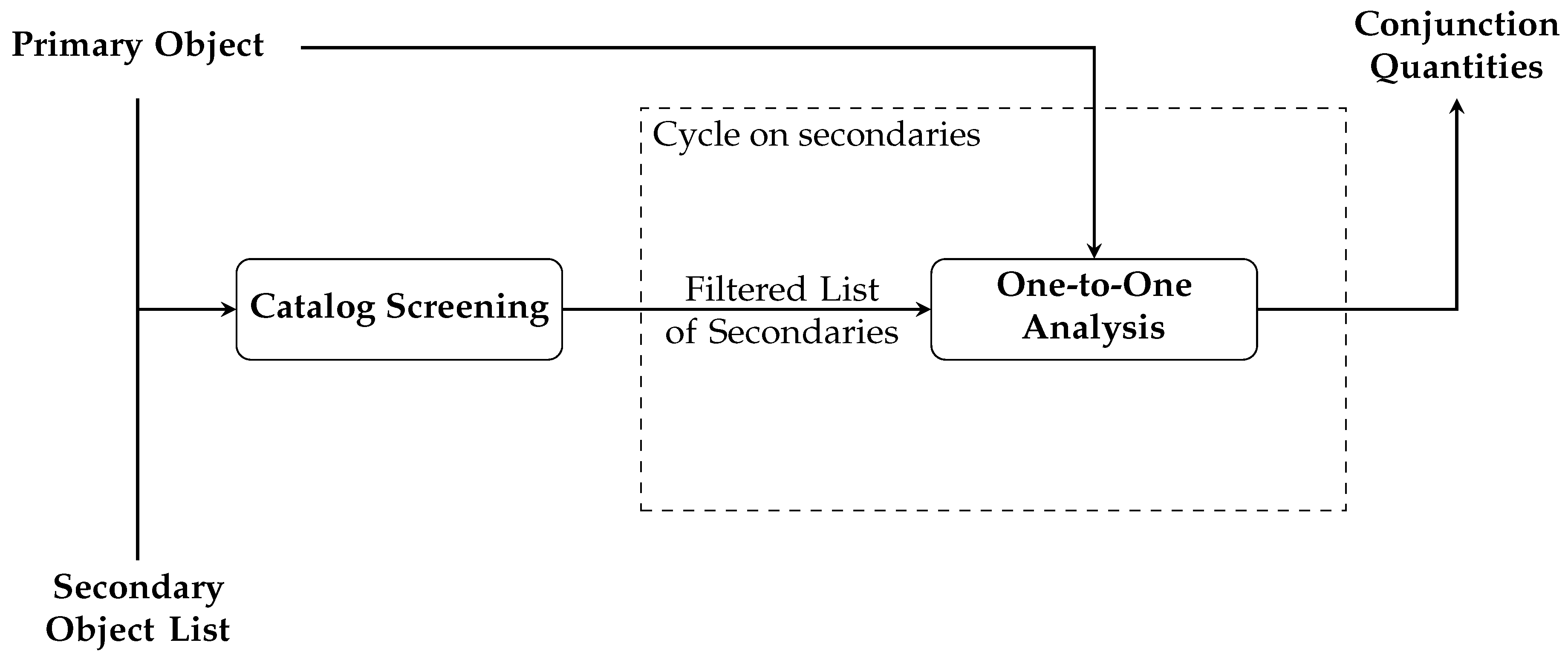
The present section provides an insight into the algorithms included in the conjunction analysis software, except for the CAM planning module, which is described in more depth in Section 5. First, a pre-processing phase is run to manage the input data before the conjunction analysis process begins. In particular, the objects’ ephemerides are evaluated at the starting epoch of the time interval of the analysis, which is set either by default or according to a specific request by the user. In addition, if no covariance is associated to an input object, this is attributed through the method presented in [28]. Then, a catalog screening is conducted, which allows the overall computational demand to be reduced. Subsequently, a one-to-one analysis for the pairs passing the filters computes the essential conjunction parameters introduced in Section 1. The overall process is represented in Figure 2.

4.1. Catalog Screening

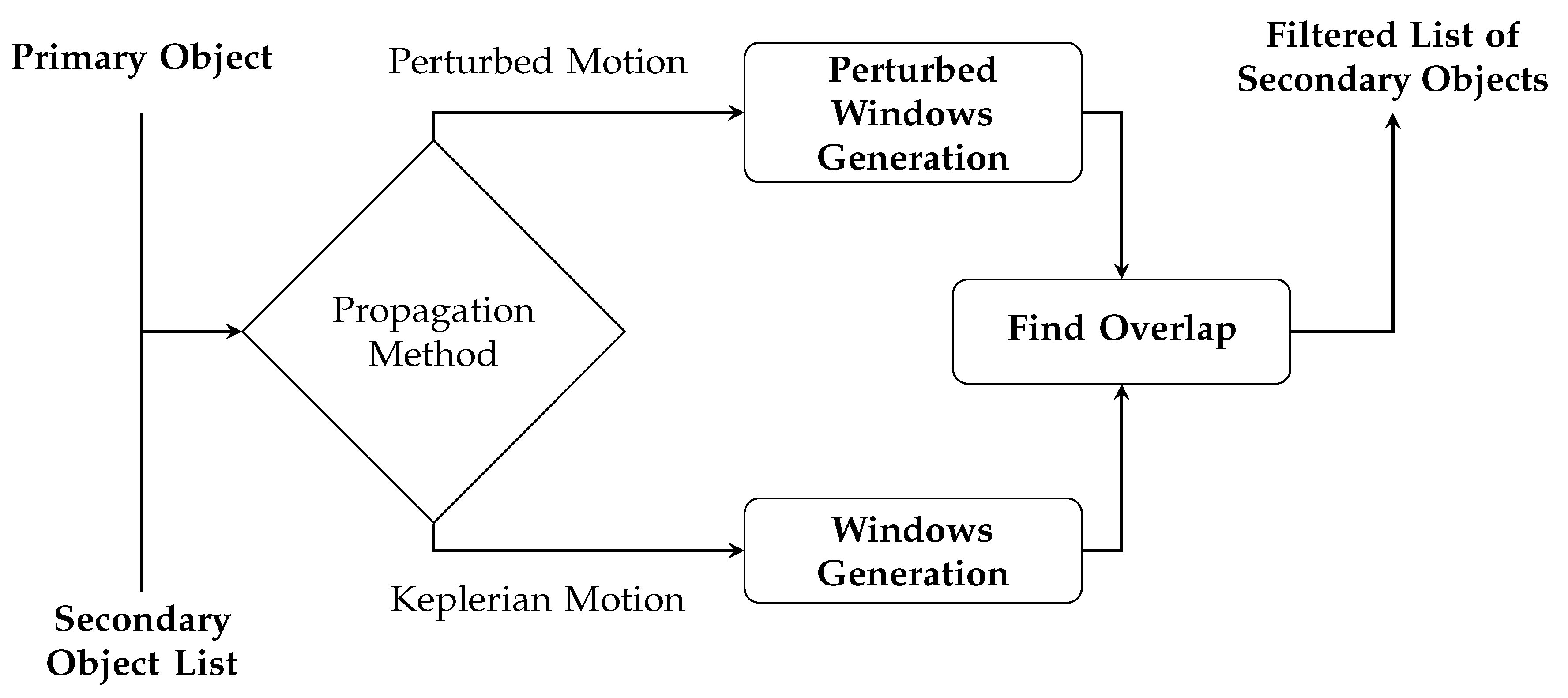
The catalog screening implements the filtering sequence outlined by Hoots et al. [29]. It operates on the concept that primary and secondary objects may not be at risk of collision due to geometric considerations and the absence of overlapping time intervals. In particular, the apogee–perigee filter (AP filter) and the orbit path filter (OP filter) work to eliminate pairs when the orbits of the objects do not permit them to approach closely. Additionally, the time filter (T filter) considers the real-time positions of space objects on their orbits, removing pairs that do not cross a region of relative proximity simultaneously.
Based on the way the filters are implemented, they may require the user to define a duration of the analysis interval. About this, it is worth remarking that, according to what is highlighted in [30], using simplified motion models in the filters may introduce errors which grow with longer analysis time windows. This issue is particularly relevant in the choice of the thresholds to be used within the criteria of the different filters, as the analysis interval length impacts the size needed to ensure precision in results. This problem can be partially attenuated by including the orbital perturbations.
Concerning the order of the filters within the catalog screening sequence, as stated in [31], this choice is driven by the computational cost associated with their operations. Given the algorithms on which the filters are based, and after their numerical validation, the following choice of the order of the filters was taken. The result is a short-listed version of the original secondary object catalog, which then enters the one-to-one analysis, as described in Section 4.2.

4.1.1. Apogee–Perigee Filter

The first filter in the series is the AP filter, as it is associated with the minimal computational requirements. It computes the apogee and perigee for each object. Subsequently, for each pair, it straightforwardly checks the following geometric criterion:
q Q < D A P
where q represents the larger perigee, Q denotes the smaller apogee, and D A P signifies a user-defined threshold distance. Alfano and Finkleman’s work [31] investigated the use of different threshold values, finally suggesting a value close to 10 km, which should guarantee an effective trade-off. For this, and for all the filters in such a screening procedure, it is crucial to underline that the more precise the orbital data, the stricter the threshold setting can be. More details on this aspect are given in [30].
The pairs satisfying Equation (2) pass the AP filter and enter the T filter, which is described below.

4.1.2. Time Filter

In the filtering process, it is vital to account for the real-time positions of both space objects on their respective orbits, extending beyond basic geometric factors. This criterion mandates that for a potential collision to be plausible, both primary and secondary objects must traverse a region of relative closeness at the same time.
The core concept of the T filter involves examining the alignment of time intervals determined by the transit of both the primary and secondary within these critical regions. Typically, two satellites can collide for a brief period before and after they cross the intersection line of the two orbital planes. To establish these periods, two orbital positions are selected around the line of nodes, and these positions are then converted into time intervals using the Kepler equation. For both the primary and secondary objects, a set of time windows is derived, which are spaced in time according to the orbital period. The subsequent step verifies possible overlapping time windows of the two objects to determine whether the pair will pass through the filter or not. In particular, multiple overlaps can be identified, that is, multiple conjunction time intervals for the same pair of objects.
In detail, the algorithm introduced by Hoots et al. [29] is applied to calculate the time windows. However, this method proves ineffective in situations involving co-planar and nearly co-planar pairs. In such cases, an alternative approach is employed in the conjunction analysis suite, which leverages the rate of change in the relative position between the two objects to identify the region of closeness. This alternative method detects the change from negative to positive values in this rate of change, signifying a local minimum. It is worth to remark that the intersection line between the two orbital planes is not stationary and evolves over time. For this reason, it is possible for the user to select an accurate propagation method, to obtain a more accurate estimation across the analysis time window, as represented in Figure 3. As mentioned above, the threshold setting of the T filter shall be selected in accordance to the length of the analysis time window.

4.1.3. Orbit Path Filter

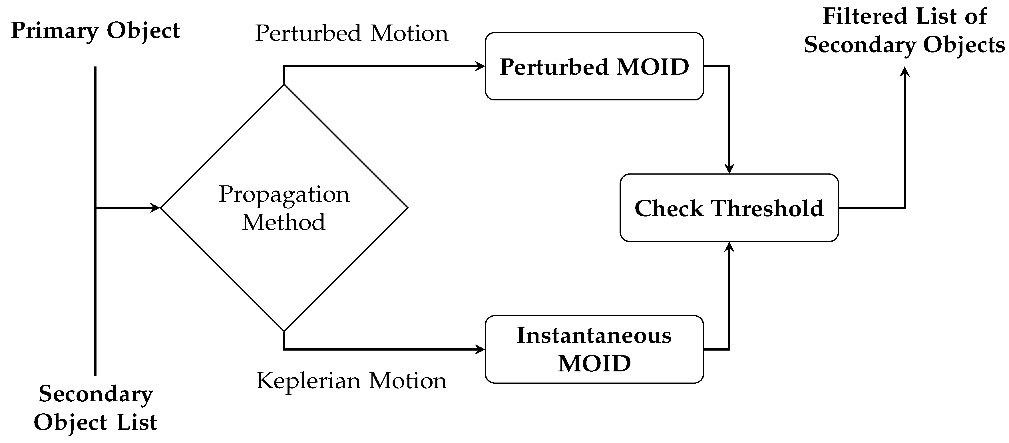
The OP filter takes as input the pairs which passed the T filter, each pair with possibly associated multiple conjunction time intervals. It relies on the determination of the minimum orbital intersection distance (MOID), which is computed for each conjunction epoch, and then compared to a threshold, based on the following criterion:
MOID < D O P
where D O P represents a user-selected threshold distance. Even for this filter, Alfano and Finkleman [31] investigated the use of different threshold values, finally suggesting a value close to 90 km, which should guarantee an effective trade-off. If Equation (3) is satisfied, the pair passes the filter and enters the one-to-one analysis described in Section 4.2.
A focused discussion shall be devoted to the MOID computation, which is based on Gronchi’s algorithm [32]. If a Keplerian propagation method is selected by the user, this approach is carried out using the orbital data available at that moment, without further refinement, and this results in a non-time-dependent MOID. However, when a more accurate propagation method is selected by the user, a specific procedure for MOID computation is activated. This latter procedure is presented in [6], and is composed of the following steps:
  • Calculate the MOID and the corresponding true anomalies using the orbital elements of the primary and secondary objects as defined at the initial epoch of the analysis time window.
  • Determine the times of flight from the current positions to the true anomalies corresponding to the MOID.
  • Propagate the states of the primary and secondary objects for the times of flight computed in the previous step.
  • Convert the propagated states into orbital elements.
  • Recalculate the MOID and the corresponding true anomalies using the updated orbital elements of the primary and secondary.
  • Compute the times of flight from the updated positions to the updated true anomalies corresponding to the updated MOID.
  • Examine these times of flight, and if they exceed a predefined threshold, repeat the process.
The overall OP filter workflow is represented in Figure 4. Given that it is the last filter of the sequence, and that the pairs passing it have already passed the T filter, temporal considerations can be made to extract useful information about the TCA. As also remarked by Hoots et al. [29], the interval of interest in which to analyze the relative motion between the two objects may be shortened to those intervals identified by the T filter. In this regard, being that the time windows of the T filter have been generated around portions of the orbits close to the line of intersection, that is in proximity to the MOID, this allows the epoch of transit of one of the two objects through the MOID to be considered as a candidate TCA.

4.2. One-to-One Analysis

The pairs which pass the AP filter, the T filter, and the OP filter exit the catalog screening step and enter the one-to-one analysis, which implements more meticulous operations. To this end, the tool processes one primary object and one secondary object at a time, as follows.
To refine the TCA candidates computed in the OP filter, the states of both objects are propagated on the time intervals identified by the T filter, and their relative positions are computed. The TCAs are refined by using the time rate of change in the relative position, based on the method presented in [29], which detects the presence of local minima. During this operation three cases can occur:
1.
The time rate of change in the relative position solely increases: this indicates that the two objects are moving away from each other, and the TCA is taken as the initial moment of the time interval.
2.
The time rate of change in the relative position exclusively decreases: in this case, the objects are approaching each other, but no local minimum is detected within the time window. Consequently, the TCA is assumed to be the final moment of the time interval.
3.
The time rate of change in the relative position undergoes a sign change from negative to positive: in this scenario, a local minimum exists within the time window, and the corresponding moment is selected as an initial estimate. This serves as a starting point for an optimization, which searches for the TCA as the epoch in which the relative position and the relative velocity between the two objects become orthogonal.
The MD is then computed as the norm of the relative position at the TCA. In the third case, it is possible to encounter multiple local minima in the relative position. If this occurs, the time corresponding to the minimum relative position norm is selected as the TCA, and the distance between the objects at that moment is recorded as the MD. In any case, the tool retains information about the other time points and their respective relative position norms for potential future use.
Following this stage, the state transition matrix, computed through the method presented in [33], is applied to propagate the objects’ covariances (possibly associated during data pre-processing) to the TCAs. Subsequently, other conventional parameters associated with a conjunction event are computed, including the PoC, which is determined based on the user’s chosen method (i.e., Chan, Patera, LAAS) and can be then modified in the maximum PoC by applying the inflating factor to the covariances, as described in Section 3
Finally, the user can choose to create the CDM file for the one-to-one analysis carried out. If for the same object pair multiple conjunctions are identified, multiple CDMs can be written coherently.

5. Collision Avoidance Algorithm

Operationally, if the PoC or the MD exceeds a threshold, it is recommended to plan a CAM, which can be executed in either a low-thrust manner [5] or an impulsive one. The algorithm developed for the ISOC Suite embeds procedures to plan impulsive maneuvers given their advanced operational status.
The process begins with the collection of data related to the collision event from a CDM, possibly returned by the conjunction analysis algorithm described in Section 4, and other essential inputs. The first step carries out optimal CAM planning using algorithms based on Keplerian assumptions. Subsequently, a refinement procedure is run including orbital perturbations.

5.1. Optimal CAM Planning

The planning phase of the CAM starts from the data extracted from the input CDM and a range of true anomalies to serve as potential locations for candidate maneuvers. In addition, optional inputs can be provided, such as user-specified upper limits for the PoC and lower limits for the MD to be achieved after the maneuver, and the option to request a tangential maneuver (that is aligned with the velocity vector direction). In the absence of user-defined thresholds, reasonable values are set as default.
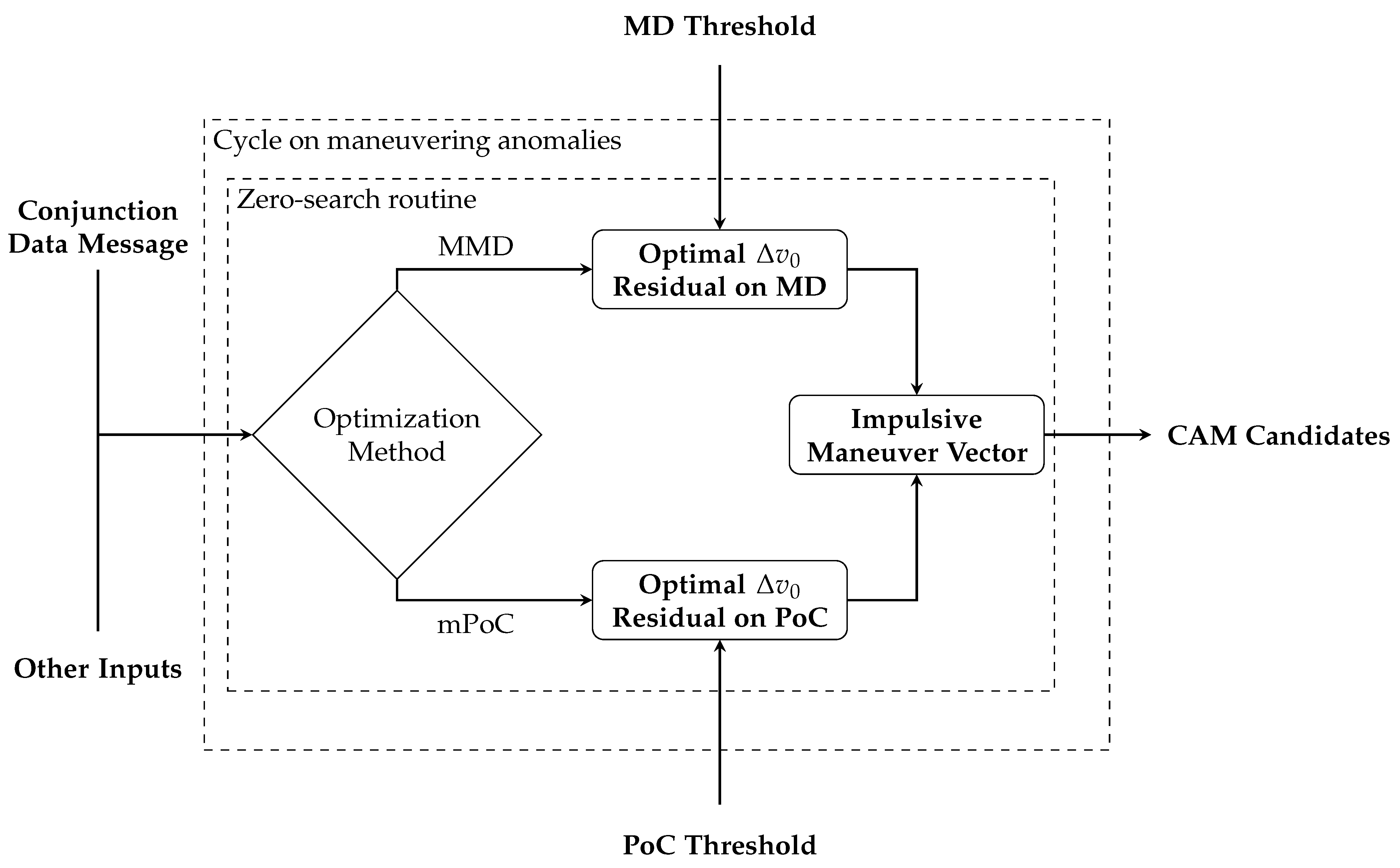
The CAM planning is performed based on the algorithm introduced by Bombardelli and Hernando-Ayuso in [34]. Thanks to a Keplerian assumption, this approach devised a linear relationship between the impulsive maneuver vector and the relative position between the primary and the secondary objects, projected onto the conjunction plane. This relationship allows the CAM planning to be defined as a quadratic optimization, which results in an eigenvalue problem. In [34], two optimization problems are established: the first seeks the maximum MD (MMD), while the second seeks the minimum PoC (mPoC). The resolution of these problems provides the direction for the impulsive maneuver vector. It is important to stress that the original formulation of this approach requires fixing the magnitude of the impulsive maneuver vector to determine its direction.
In the ISOC Suite, as described above, the upper limit for the PoC and the lower limit for the MD to have at the end of the maneuver are either given as input to the CAM planning or defined through default quantities. Then, in the optimization process the eigenvalue problem is solved to derive the direction of the maneuver vector, which is then multiplied by an impulse magnitude v 0 to compute the conjunction parameter at the end of the maneuver (either MD or PoC). These steps are embedded in a cost function which computes the residual absolute value of either the MD or PoC with respect to the input threshold quantities. The zero of this cost function is searched for through the Newton method [35], and the related v 0 is returned.
These operations are performed for all the true anomaly candidate locations given as input, and, for each of them, the process returns the minimum cost maneuver which matches either the desired MD or PoC. Finally, all these maneuver candidates are ranked based on the impulse magnitude v 0 . The overall process is represented in Figure 5.
In the case of a tangential maneuver, the MMD and mPoC optimization problems are not solved, and therefore, the maneuver direction is not optimized, and it is determined using the flight path angle, as shown in Figure 6. The only variable to be determined is the magnitude of the impulse v 0 , which is computed, for each true anomaly candidate location, through a zero-search of the same cost function described above. At the end, the list of maneuver candidates are returned and ranked according to v 0 .

5.2. CAM Refinement

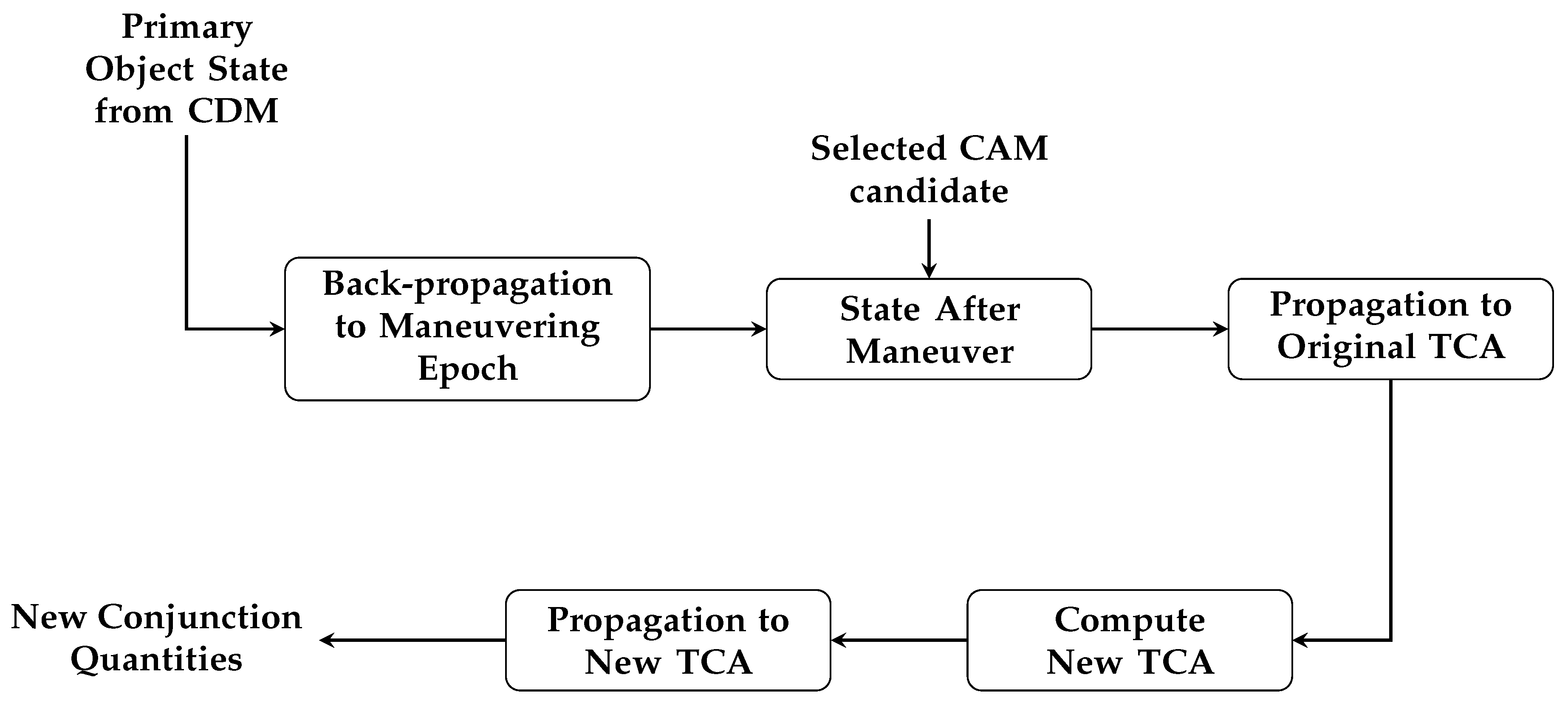
The CAM planning procedure described above is based on [34], which exploits a Keplerian assumption. Thus, if requested by the user, the performance associated with a specific maneuver (selected from the list of candidates) shall be verified also considering orbital perturbations. A reasonable way is to start verifying the compliance of the minimum cost CAM, that is, the candidate featuring the smallest impulse magnitude, or the maneuver associated with one of the locations that best suits other possible users’ needs. To this end, the primary object orbital state, which is defined at the TCA (being given by the input CDM), is back-propagated to the maneuvering epoch. This step is accomplished according to a high-fidelity propagator which considers orbital perturbations. Then, the maneuver to be verified is applied, and the state after the maneuver is propagated to the original TCA. Given that the primary object follows a new trajectory after the maneuver, updated conjunction quantities are computed: the original TCA is used as the first guess to compute the new TCA, to which both primary and secondary objects are propagated, and the new MD and PoC are computed. If they do not respect the threshold quantities, the user can opt to select an alternative CAM among the candidates (for instance, the next in the v 0 ranking), to then verify its compliance through the refinement process. The CAM refinement process is represented in Figure 7.

6. Validation

The most remarkable validation steps of the ISOC Suite for conjunction analysis are reported here. All the tests were implemented in MATLAB (R2022b) [36] and run with an Intel(R) Core(TM) i7-12700 CPU @ 2.10 GHz processor with 16 GB of RAM.

6.1. Catalog Screening

To validate the catalog screening module, the space objects catalog used is represented by the two-line elements (TLEs) downloaded from the Spacetrack website [37]. Thus, the test reported here is a real-case validation rather than a simulation, given that the catalog considered is composed of real space object data. The validation is performed on a scenario featuring a single primary object, considered as a user’s asset of interest, and the complete space objects catalog as secondaries. This scenario, which holds operational significance, constitutes the “one vs. all” procedure and results in a short-list of potentially colliding secondary objects, according to the results of the filtering sequence. It is worth remarking that performing the “one vs. all” procedure for all the space objects in the catalog results in the “all vs. all” analysis.
As remarked in Section 4.1, the catalog screening module was designed to minimize the computational workload. Consequently, the focus is on evaluating the time taken by each filter to execute its operations and the number of pairs that are eliminated at each stage. Regarding the choice of the filter thresholds, the considerations made in Section 4.1 about the suggested values have been used for the selected values reported in Table 1. In particular, to prevent the loss of possible conjunction events, slightly higher values have been used with respect to the suggested ones.
Table 1 also presents the outcomes for an analysis spanning one week, conducted from 4 June 2022 to 11 June 2022. This analysis involved a single primary object and a catalog comprising 24,219 secondary objects, which is returned by the pre-processing. As delineated in Section 4, this is the initial phase of the catalog screening, in which the objects are propagated to the starting epoch of the analysis time window and covariances are possibly associated.
From Table 1 the key role played by the catalog screening is clear: out of the 24,219 pairs at the end of the pre-processing phase, just 1655 (that is, 6.83%) pass all the filters and proceed to the one-to-one analysis. The overall computational demand is about 24 min, of which the T filter represents the main part, as it requires the computation of the time evolution of the objects’ relative positions.
It is important to highlight that for this conjunction analysis validation the “one-to-one” step demanded approximately 3 h of computation. Thus, considering that the complete list of secondary objects was reduced by about 93.2%, the overall computational demand for the conjunction analysis would have been around 41 h if no catalog screening have been conducted.

6.2. Probability of Collision

The validation of the 2D PoC methods is carried out in a twofold way. The first test is based on cases extracted from the literature, while the second one exploits data from the ESA Collision Avoidance Challenge [38]. Differently from Section 6.1, both analyses are numerical, as they exploit synthetic data.
The first validation is based on the test cases outlined in [21,39]. Table 2 reports the input data, in terms of relative position and standard deviations in the B-plane ( x m , y m , σ x , and σ y ), hard body radius (R), and ratios which are significant for the analysis ( σ x / σ y and R / σ y ). The validation results are presented in Table 3 and compared to the reference values either provided in [21] (in terms of both the Patera and Chan methods, separately) or in [39] (expressed as a Monte Carlo simulation result with 1 × 10 8 samples), depending on the literature source considered for the cases. Overall, it is possible to notice the alignment between the results produced by the implemented PoC methods and the reference values. However, in “Alfano case 3” and “Alfano case 6”, the Chan method provides a result one order of magnitude different from the reference value, while both the Patera and LAAS methods converge to an estimation closer to the reference. From Table 2 it is possible to observe that these two cases are connected to a small R / σ y ratio, which is a key parameter in assessing the numerical stability of the analytical PoC computation methods [20]. Indeed, in such methods, high orders are required to achieve a precise PoC computation, but the large orders can introduce term cancellations, resulting in numerical instability. The LAAS method mitigates this problem through the incorporation of the pre-conditioner, as mentioned in Section 3, allowing both a fast and a robust PoC computation. It is worth to stress that the argument of the LAAS pre-conditioner is R 2 / ( 2 σ y 2 ) , which retraces the R / σ y ratio mentioned above. In any case, it is important to observe that the implementation of multiple methods for PoC computation within the ISOC Suite enables a robust analysis.
The second validation of the aforementioned PoC methods is based on synthetic data extracted from the Collision Avoidance Challenge database of the ESA [38]. Three test cases for LEO orbits are presented, with the data in Table 4 and the corresponding results in Table 5. The implemented PoC methods provide results in agreement with the reference values, confirming the robustness of the implemented algorithms. It is worth remarking that the largest errors are related to the Chan method, and considerations about the numerical stability of the analytic methods can be conducted analogously to those above.

6.3. Collision Avoidance Maneuver

Numerical validation of the optimal CAM planning calculations is conducted by replicating the Iridium-Cosmos collision test case described in [34]. The analysis examines the trends in MD and PoC as a function of the true anomaly where the maneuver is executed. Specifically, the results achieved by the MMD and mPoC maneuvers, outlined in [34] and discussed in Section 5, are represented in Figure 8 for a value of the impulse magnitude of 10 cm/s, which has been therefore fixed for this analysis and not computed according to the zero-search routine explained in Section 5.1.
The comparison reveals that both methods successfully achieve their respective objectives, either minimizing or maximizing the relevant quantity according to their formulations. This is emphasized by the fact that, for both MD and PoC, the specific method (MMD or mPoC) is able to provide better results with respect to the other in terms of the objective quantity to be either maximized or minimized. The presence of jumps that are visible for some ranges of the maneuvering anomaly is well explained in [34], where the authors state that they are due to the presence of an optimality constraint. Additionally, it is worth noting that a larger maneuvering anomaly, signifying that the maneuver is executed well in advance of the TCA, results in improved performance in terms of the final MD or PoC. This underscores the significance of planning and conducting collision avoidance maneuvers with reasonable advance.

7. Operational Scenario

In this section, the performance of the conjunction analysis software developed for the ISOC Suite is evaluated through operational scenarios. In particular, both the catalog screening and the CAM planning are assessed based on real data.

7.1. Catalog Screening

To validate the screening process, a conjunction alerted by Spacetrack [37] is used, and the related TCA is taken as reference. A screening on the entire Spacetrack catalog is run on an analysis time window of one week, which includes the reference TCA, to verify whether the tool is capable of detecting that conjunction. In particular, it is worth to highlight that the TLEs for the two objects involved in the event are taken at the starting epoch of this time window, to better retrace the operational need to detect future conjunctions.
The result of this operation is showed in Table 6: the objects pair passes through the entire filtering sequence, and the TCA computed during the one-to-one analysis presents less than a 0.13 s difference with respect to the reference value.

7.2. Collision Avoidance Maneuver

The CAM module is tested using a real CDM as input, from which mean states, covariances, and other quantities of the considered pair are extracted. Initially, thresholds of 6000 m for the MD and 10 7 for the PoC are set, which are reasonable values considering that the two objects are on GEO orbits. Then, the CAM planning procedure described in Section 5 is run. Figure 9 illustrates that for both the MMD and mPoC cases the optimized quantity aligns with the required threshold, which is either the MD (for the MMD maneuver) or the PoC (for the mPoC one). This is an important result given that the algorithm’s purpose is to find the minimum impulse magnitude to match the user’s threshold.
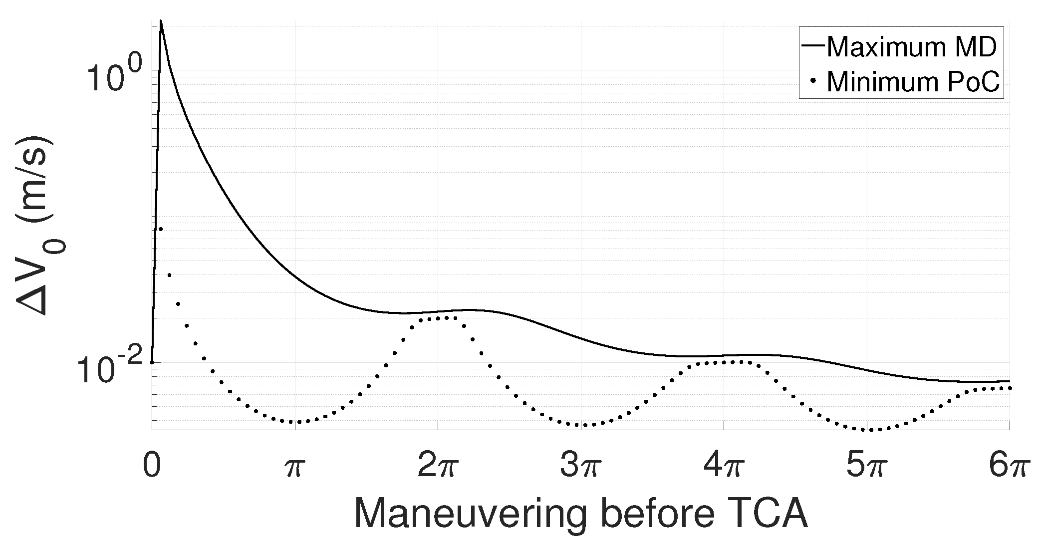
Figure 10 displays the resulting values of the optimized impulse magnitude as a function of the maneuvering anomaly. As expected, the figure shows that the earlier the maneuver with respect to the TCA, the lower the required impulse. The peak near zero degrees indicates that the impulse needed to meet the thresholds by executing a maneuver very close to the conjunction anomaly would be very expensive.
As explained in Section 5, the optimal CAM planning phase provides multiple candidate CAMs, one for each true anomaly considered to perform the maneuver, and the user can select the least expensive and run the refinement procedure to verify its performance, taking into account orbital perturbations in the process. To assess the algorithm’s performance, among the candidates computed for the same analysis as above through the MMD maneuver, the maneuver with the lowest impulse magnitude is selected, whose characteristics are listed in Table 7. The overall CAM planning performance is listed in Table 8: the values of the MD and PoC given in the CDM (first column), those that should be obtained with the optimal CAM, i.e., exploiting the Keplerian assumption (second column), and those resulting from the CAM refinement phase, both at the original (third column) and at the new TCA (fourth column). It is possible to observe that the MD computed by the optimal CAM planning matches the 6000 m threshold, as expected given the MMD maneuver requested. In addition, it is worth noting that the values computed through the optimal CAM planning slightly differ from the refined ones at the original TCA. In any case, they still respect the thresholds, confirming that the maneuver described in Table 7 respects the input thresholds.

8. Conclusions

This paper provides an in-depth overview of the conjunction analysis software for SST operations, which is integrated into the ISOC Suite. It facilitates the detection and detailed characterization of potential conjunction events between a selected catalog of primary objects and the comprehensive space catalog. The software can manage different formats of the input files and the settings of the parameters can be modified by the user, and this flexibility makes the tool versatile and accommodates different operator’s requirements.
First, a catalog screening applies a filtering sequence to detect possible colliding pairs of space objects, and this short-listing allows a much faster computation in the one-to-one analysis, in which each conjunction is characterized in terms of TCA, MD, and PoC. In addition, once a potential colliding pair is identified, the tool offers the possibility to compute multiple candidate CAMs to match specific criteria in terms of the PoC and MD. From the range of output options, the user can select a candidate maneuver (typically the least expensive one) to verify whether the criteria are respected considering orbital perturbations, both at the original and at the new TCA.
The validation and the operational scenario analysis proved both the efficiency and the accuracy of the developed software. In the future, the ISOC Suite could be enriched with dedicated procedures to manage conjunctions which do not respect the short-term encounter model assumptions, through methods developed for the long-term case.
Author Contributions

Conceptualization, M.P., A.P., M.R. and F.D.P.; methodology, S.B., M.F.M. and P.D.L.; software, S.B. and M.F.M.; validation, S.B. and M.F.M.; formal analysis, S.B., M.F.M. and P.D.L.; investigation, S.B. and M.F.M.; resources, M.P., A.P., M.R. and F.D.P.; data curation, S.B., M.F.M. and P.D.L.; writing—original draft preparation, S.B. and M.F.M.; writing—review and editing, S.B., M.F.M., M.P., A.P., M.R. and F.D.P.; visualization, S.B., M.F.M. and P.D.L.; supervision, P.D.L.; project administration, P.D.L. and M.P.; funding acquisition, P.D.L. and M.P. All authors have read and agreed to the published version of the manuscript.

Funding

This research received no external funding.

Data Availability Statement

Data are contained within the article.

Acknowledgments

The authors are grateful to Leonardo Company for the collaboration in the ISOC Suite realization.

Conflicts of Interest

The authors declare no conflicts of interest.

Abbreviations

The following abbreviations are used in this manuscript:
AMAeronautica Militare
APApogee–perigee filter
C-SSASpace Situational Awareness Centre
CACollision avoidance service
CAMCollision avoidance maneuver
CCSDSConsultative Committee for Space Data Systems
CDMConjunction Data Message
COTSCommercial off-the-shelf
ESAEuropean Space Agency
EUSSTEuropean Union Space Surveillance and Tracking Consortium
FGFragmentation service
GEOGeostationary orbit
INAFIstituto Nazionale di Astrofisica (Astrophysics National Institute)
LEOLow Earth orbit
MDMiss distance
MMDMaximum miss distance maneuver
MOIDMinimum orbital intersection distance
mPoCMinimum probability of collision maneuver
OEMOrbit Ephemeris Message
OPOrbit path filter
OPMOrbit Parameter Message
PoCProbability of collision
RERe-entry service
SSASpace Situational Awareness
SSTSpace surveillance and tracking
TTime filter
TCATime of closest approach
TLEsTwo-line elements

References

  1. ESA Space Debris Office. ESA’s Annual Space Environment Report; ESA Space Debris Office: Darmstadt, Germany, 2022. [Google Scholar]
  2. Montaruli, M.F.; Bonaccorsi, S.; Muciaccia, A.; Giudici, L.; Di Lizia, P.; Colombo, C. Assessment of the CZ-6A R/B and the H-2A DEB fragmentation events. In Proceedings of the Aerospace Europe Conference 2023-Joint 10th EUCASS-9th CEAS Conference, Lausanne, Switzerland, 9–13 July 2023; pp. 1–10. [Google Scholar] [CrossRef]
  3. Flohrer, T.; Krag, H. Space surveillance and tracking in ESA’s SSA programme. In Proceedings of the 7th European Conference on Space Debris, Darmstadt, Germany, 18–21 April 2017; Volume 7. [Google Scholar]
  4. European Union Space Surveillance and Tracking. EUSST Service Portfolio; European Union Satellite Centre: Madrid, Spain, 2021. [Google Scholar]
  5. De Vittori, A.; Palermo, M.F.; Lizia, P.D.; Armellin, R. Low-Thrust Collision Avoidance Maneuver Optimization. J. Guid. Control Dyn. 2022, 45, 1815–1829. [Google Scholar] [CrossRef]
  6. Montaruli, M.F.; Di Lizia, P.; Cordelli, E.; Ma, H.; Siminski, J. A stochastic approach to detect fragmentation epoch from a single fragment orbit determination. Adv. Space Res. 2023, 72, 3713–3733. [Google Scholar] [CrossRef]
  7. Muciaccia, A.; Facchini, L.; Montaruli, M.F.; Purpura, G.; Detomaso, R.; Colombo, C.; Massari, M.; Di Lizia, P.; Di Cecco, A.; Salotti, L.; et al. Radar observation and recontruction of Cosmos 1408 fragmentation. J. Space Saf. Eng. 2023, in press. [CrossRef]
  8. Cipollone, R.; Montaruli, M.; Faraco, N.; Di Lizia, P.; Massari, M.; De Vittori, A.; Peroni, M.; Panico, A.; Cecchini, A. A re-entry analysis software module for Space Surveillance and Tracking operations. In Proceedings of the International Astronautical Congress, Paris, France, 18–22 September 2022. [Google Scholar]
  9. De Vittori, A.; Cipollone, R.; Di Lizia, P.; Massari, M. Real-time space object tracklet extraction from telescope survey images with machine learning. Astrodynamics 2022, 6, 205–218. [Google Scholar] [CrossRef]
  10. Montaruli, M.F.; Facchini, L.; Lizia, P.D.; Massari, M.; Pupillo, G.; Bianchi, G.; Naldi, G. Adaptive track estimation on a radar array system for space surveillance. Acta Astronaut. 2022, 198, 111–123. [Google Scholar] [CrossRef]
  11. Cordelli, E.; Vananti, A.; Schildknecht, T. Analysis of laser ranges and angular measurements data fusion for space debris orbit determination. Adv. Space Res. 2020, 65, 419–434. [Google Scholar] [CrossRef]
  12. Bianchi, G.; Bortolotti, C.; Roma, M.; Pupillo, G.; Naldi, G.; Lama, L.; Perini, F.; Schiaffino, M.; Maccaferri, A.; Mattana, A.; et al. Exploration of an innovative ranging method for bi-static radar, applied in LEO Space Debris surveying and tracking. In Proceedings of the 71st International Astronautical Congress, Virtual, 12–14 October 2020. [Google Scholar]
  13. Bianchi, G.; Naldi, G.; Fiocchi, F.; Di Lizia, P.; Bortolotti, C.; Mattana, A.; Maccaferri, A.; Magro, A.; Roma, M.; Schiaffino, M.; et al. A new concept of bi-static radar for space debris detection and monitoring. In Proceedings of the 2021 International Conference on Electrical, Computer, Communications and Mechatronics Engineering (ICECCME), Flic en Flac, Mauritius, 7–8 October 2021. [Google Scholar] [CrossRef]
  14. Bianchi, G.; Montaruli, M.F.; Roma, M.; Mariotti, S.; Di Lizia, P.; Maccaferri, A.; Facchini, L.; Bortolotti, C.; Minghetti, R. A new concept of transmitting antenna on bi-static radar for space debris monitoring. In Proceedings of the 2021 International Conference on Electrical, Computer, Communications and Mechatronics Engineering (ICECCME), Malé, Maldives, 16–18 November 2022. [Google Scholar] [CrossRef]
  15. Pastor, A.; Escribano, G.; Sanjurjo-Rivo, M.; Escobar, D. Satellite maneuver detection and estimation with optical survey observations. J. Astronaut. Sci. 2022, 69, 879–917. [Google Scholar] [CrossRef]
  16. Maestrini, M.; De Luca, M.A.; Di Lizia, P. Relative Navigation Strategy About Unknown and Uncooperative Targets. J. Guid. Control. Dyn. 2023, 46, 1708–1725. [Google Scholar] [CrossRef]
  17. Faraco, N.; Maestrini, M.; Di Lizia, P. Instance Segmentation for Feature Recognition on Noncooperative Resident Space Objects. J. Spacecr. Rocket. 2022, 59, 2160–2174. [Google Scholar] [CrossRef]
  18. Montaruli, M.F.; Purpura, G.; Cipollone, R.; De Vittori, A.; Facchini, L.; Di Lizia, P.; Massari, M.; Peroni, M.; Panico, A.; Cecchini, A.; et al. A software suite for orbit determination in Space Surveillance and Tracking applications. In Proceedings of the Aerospace European Conference 2022-Joint 9th EUCASS-9th CEAS Conference, Paris, France, 27 June–1 July 2022; pp. 1–12. [Google Scholar] [CrossRef]
  19. Consultative Committee for Space Data Systems. Conjunction Data Message; Consultative Committee for Space Data Systems, 2013. [Google Scholar]
  20. Montaruli, M.F. Collision Risk Assessment and Collision Avoidance Maneuver Planning. Master’s Thesis, Politecnico di Milano, Milan, Italy, 2019. [Google Scholar]
  21. Chan, F.K. Spacecraft Collision Probability; Aerospace Press: El Segundo, CA, USA, 2008. [Google Scholar]
  22. Coppola, V.T. Including velocity uncertainty in the probability of collision between space objects. In Proceedings of the AAS/AIAA Spaceflight Mechanics Meeting, Charleston, SC, USA, 29 January–2 February 2012; pp. 2012–2247. [Google Scholar]
  23. Alfano, S.; Oltrogge, D. Probability of Collision: Valuation, variability, visualization, and validity. Acta Astronaut. 2018, 148, 301–316. [Google Scholar] [CrossRef]
  24. Patera, R.P. Calculating Collision Probability for Arbitrary Space Vehicle Shapes via Numerical Quadrature. J. Guid. Control. Dyn. 2005, 28, 1326–1328. [Google Scholar] [CrossRef]
  25. Serra, R.; Arzelier, D.; Joldes, M.; Lasserre, J.B.; Rondepierre, A.; Salvy, B. Fast and Accurate Computation of Orbital Collision Probability for Short-Term Encounters. J. Guid. Control Dyn. 2016, 39, 1009–1021. [Google Scholar] [CrossRef]
  26. Balch, M.S. A Corrector for Probability Dilution in Satellite Conjunction Analysis. In Proceedings of the 18th AIAA Non-Deterministic Approaches Conference, San Diego, CA, USA, 4–8 January 2016. [Google Scholar]
  27. Thomassin, J.; Laurens, S.; Toussaint, F. ASTERIA: Autonomous collision risks management. Acta Astronaut. 2022, 200, 599–611. [Google Scholar] [CrossRef]
  28. Flohrer, T.; Krag, H.; Klinkrad, H. Assessment and Categorization of TLE Orbit Errors for the US SSN Catalogue. In Proceedings of the Advanced Maui Optical and Space Surveillance Technologies Conference, Maui, HI, USA, 16–19 September 2008; Volume 8. [Google Scholar]
  29. Hoots, F.R.; Crawford, L.L.; Roehrich, R.L. An analytic method to determine future close approaches between satellites. J. Celest. Mech. Dyn. Astron. 1984, 33, 143–158. [Google Scholar] [CrossRef]
  30. Woodburn, J.; Coppola, V.; Stoner, F. A description of filters for minimizing the time required for orbital conjunction computations. Adv. Astronaut. Sci. 2009, 135, 1157–1173. [Google Scholar]
  31. Alfano, S.; Finkleman, D. On selecting satellite conjunction filter parameters. Acta Astronaut. 2014, 99, 193–200. [Google Scholar] [CrossRef]
  32. Gronchi, G.F. On the Stationary Points of the Squared Distance between Two Ellipses with a Common Focus. SIAM J. Sci. Comput. 2002, 24, 61–80. [Google Scholar] [CrossRef]
  33. Shepperd, S.W. Universal Keplerian state transition matrix. Celest. Mech. 1985, 35, 129–144. [Google Scholar] [CrossRef]
  34. Bombardelli, C.; Hernando-Ayuso, J. Optimal Impulsive Collision Avoidance in Low Earth Orbit. J. Guid. Control. Dyn. 2015, 38, 217–225. [Google Scholar] [CrossRef]
  35. Coleman, T.F.; Li, Y. An Interior Trust Region Approach for Nonlinear Minimization Subject to Bounds. SIAM J. Optim. 1996, 6, 418–445. [Google Scholar] [CrossRef]
  36. MATLAB. 9.13.0.2126072 (R2022b); The MathWorks Inc.: Natick, MA, USA, 2022. [Google Scholar]
  37. Space-Track. Space-Track Website. 2022. Available online: https://www.space-track.org/auth/login (accessed on 6 June 2022).
  38. ESA Advanced Concepts Team. ESA Collision Avoidance Challenge. 2023. Available online: https://kelvins.esa.int/collision-avoidance-challenge/data/ (accessed on 20 March 2023).
  39. Alfano, S. Satellite conjunction Monte Carlo analysis. Adv. Astronaut. Sci. 2009, 134, 2007–2024. [Google Scholar]
Figure 1. ISOC architecture.
Aerospace 11 00122 g001
Figure 2. Flow diagram of the conjunction analysis algorithm.
Aerospace 11 00122 g002
Figure 3. Flow diagram of the time filter.
Aerospace 11 00122 g003
Figure 4. Flow diagram of the orbit path filter.
Aerospace 11 00122 g004
Figure 5. Flow diagram of the optimal CAM candidates computation.
Aerospace 11 00122 g005
Figure 6. Flow diagram of the tangential CAM candidates computation.
Aerospace 11 00122 g006
Figure 7. Flow diagram of the CAM refinement.
Aerospace 11 00122 g007
Figure 8. Validation results for the optimal CAM planning. The plots report, for the Iridium-Cosmos conjunction described in [34], the MD (a) and PoC (b) trends as a function of the maneuvering point before the TCA, expressed as true anomaly difference, for a value of the impulse magnitude of 10 cm/s. It is possible to notice that both methods successfully achieve their respective objectives, either minimizing or maximizing the relevant quantity according to their formulations.
Aerospace 11 00122 g008
Figure 9. Real test results for the optimal CAM planning: MD and PoC trends. The plots report the MD (a) and PoC (b) trends as a function of the maneuvering point before the TCA, expressed in true anomaly difference. It is possible to notice that the MD and PoC align with the values in the MMD and mPoC maneuvers, respectively.
Aerospace 11 00122 g009
Figure 10. Real test results for the optimal CAM planning: impulse magnitude. The trend in the maneuvering impulse magnitude is represented as a function of the maneuvering point before the TCA, expressed in true anomaly difference. It is possible to notice that the earlier the maneuver with respect to the TCA, the lower the required impulse.
Aerospace 11 00122 g010
Table 1. Validation results for the catalog screening. The 24,219 input pairs are short-listed to 1655, that is, 6.83% of the original data set. The computational demand is about 24 min.
Threshold (km)Filtered PairsRemaining PairsComputational Time (s)
Pre-process--24,21966.09
AP filter3019,78344360.02
T filter30216222741308.98
OP filter100619165566.84
Table 2. Validation data for the PoC computation for the literature test cases. The data are based on [21] (first 12 cases) and [39] (last 2 cases) and are reported as relative position and standard deviations in the B-plane ( x m , y m , σ x , and σ y ), hard body radius (R), and ratios which are significant for the analysis ( σ x / σ y and R / σ y ).
σ x σ y R x m y m σ x / σ y R / σ y
Chan case 15025510020.2
Chan case 25025501020.2
Chan case 37525510030.2
Chan case 47525501030.2
Chan case 530001000101000030.01
Chan case 630001000100100030.01
Chan case 7300010001010,000030.01
Chan case 83000100010010,00030.01
Chan case 910,00010001010,0000100.01
Chan case 1010,000100010010,000100.01
Chan case 1130001000505000030.05
Chan case 1230001000500500030.05
Alfano case 3114.258521.41018150.15916−3.8872181.0240710.63694
Alfano case 61778.017702.2009010−1.2531−2.1046807.858644.54359
Table 3. Validation results for the PoC computation for the literature test cases. The results are compared to the reference values in [21] (first 12 cases), in terms of both the Patera and Chan methods, and in [39] (last 2 cases), expressed as a Monte Carlo simulation result with 1 × 10 8 samples. Generally, it is possible to notice that the results produced by the implemented PoC methods are in agreement with the reference values, except for the Chan method in “Alfano case 3” and “Alfano case 6”. This is due to the truncation of the expansion terms in the analytical formulation. The Patera method is not affected by this problem, being numerical, while the LAAS method (analytical) solves it thanks to the pre-conditioner.
Reference
Patera
Reference
Chan
PateraChanLAAS
Chan case 19.741 × 10 3 9.754 × 10 3 9.742 × 10 3 9.754 × 10 3 9.742 × 10 3
Chan case 29.181 × 10 3 9.189 × 10 3 9.181 × 10 3 9.189 × 10 3 9.181 × 10 3
Chan case 36.571 × 10 3 6.586 × 10 3 6.571 × 10 3 6.586 × 10 3 6.571 × 10 3
Chan case 46.125 × 10 3 6.135 × 10 3 6.125 × 10 3 6.135 × 10 3 6.125 × 10 3
Chan case 51.577 × 10 5 1.577 × 10 5 1.577 × 10 5 1.577 × 10 5 1.577 × 10 5
Chan case 61.011 × 10 5 1.011 × 10 5 1.011 × 10 5 1.011 × 10 5 1.011 × 10 5
Chan case 76.443 × 10 8 6.443 × 10 8 6.443 × 10 8 6.443 × 10 8 6.443 × 10 8
Chan case 83.219 × 10 27 3.216 × 10 27 3.219 × 10 27 3.216 × 10 27 3.219 × 10 27
Chan case 93.033 × 10 6 3.033 × 10 6 3.033 × 10 6 3.033 × 10 6 3.033 × 10 6
Chan case 109.656 × 10 28 9.645 × 10 28 9.656 × 10 28 9.645 × 10 28 9.656 × 10 28
Chan case 111.039 × 10 4 1.039 × 10 4 1.039 × 10 4 1.039 × 10 4 1.039 × 10 4
Chan case 121.564 × 10 9 1.556 × 10 9 1.564 × 10 9 1.556 × 10 9 1.564 × 10 9
Monte Carlo PateraChanLAAS
Alfano case 31.008 × 10 1 1.004 × 10 1 2.445 × 10 2 1.003 × 10 1
Alfano case 64.300 × 10 3 4.335 × 10 3 1.081 × 10 2 4.335 × 10 3
Table 4. Validation data for the PoC computation for the ESA Collision Avoidance Challenge test cases [38]. The data reported are: relative position and standard deviations in the B-plane ( x m , y m , σ x , and σ y ), hard body radius (R), and ratios which are significant for the analysis ( σ x / σ y and R / σ y ).
σ x σ y R x m y m σ x / σ y R / σ y
Case 172.064526.841629.7120.712037.87552.68481.1069
Case 2631.270826.760023−14.3269345.031623.59010.8595
Case 32719.200031.334923−18.6580665.755786.77850.7340
Table 5. Additional validation results for the PoC computation for the ESA Collision Avoidance Challenge test cases [38]. The implemented methods return PoC estimations in agreement with the reference ones. The largest errors are related to the Chan method, and this is due to the truncation of the expansion terms in the analytical formulation, which is solved by the pre-conditioner in the LAAS approach and is absent in the Patera method, as the latter applies a numerical scheme.
ReferencePateraChanLAAS
Case 11.360 × 10 1 1.362 × 10 1 1.384 × 10 1 1.360 × 10 1
Case 21.094 × 10 2 1.096 × 10 2 1.116 × 10 2 1.096 × 10 2
Case 32.4146 × 10 3 2.4173 × 10 3 2.5201 × 10 3 2.4173 × 10 3
Table 6. Real test results for the catalog screening. The same conjunction as the one detected by Spacetrack [37] is found out, and the computed TCA occurs about 0.13 s later than the reference value.
Time Interval
1 July 2022 00:00:007 July 2022 00:00:00
Object IDObject Epoch
5079229 June 2022 17:48:25
5078729 June 2022 19:30:47
TCA (computed)TCA (reference)
3 July 2022 04:44:25.4943 July 2022 04:44:25.368
Table 7. Real test data for the CAM refinement. The characteristics of the CAM candidate returned by the optimal CAM planning phase and selected for the refinement phase are represented in terms of maneuvering anomaly (in degrees), distance to collision (in orbits), and impulse magnitude. Also, the collision anomaly (in degrees) is reported.
Collision AnomalyManeuvering AnomalyDistance to CollisionImpulse Magnitude
170.96 deg214.596 deg2.88 orbits7.356 × 10 3 m/s
Table 8. Real test results for the CAM refinement. The table reports the values of MD and PoC given in the CDM (first column), those that should be obtained with the optimal CAM, i.e., exploiting the Keplerian assumption (second column), through an MMD maneuver, and those resulting from the CAM refinement phase, both at the original (third column) and at the new TCA (fourth column). It is possible to observe that the MD computed by the optimal CAM planning matches the 6000 m threshold given as input, as expected considering the MMD maneuver requested. Such a requirement is also respected considering the CAM refinement output, both at the original and at the new TCA.
CDMOptimalRefined (Original TCA)Refined (New TCA)
MD (m)294.90160006042.256001.4
PoC1.102 × 10 3 3.812 × 10 8 3.703 × 10 8 3.704 × 10 8
Disclaimer/Publisher’s Note: The statements, opinions and data contained in all publications are solely those of the individual author(s) and contributor(s) and not of MDPI and/or the editor(s). MDPI and/or the editor(s) disclaim responsibility for any injury to people or property resulting from any ideas, methods, instructions or products referred to in the content.